1. Introduction
With the rapid development of industrialization, environmental pollution has become increasingly prominent, especially air and soil pollution, which pose serious threats to human health and the ecosystem. Thus, developing efficient, stable, and environmentally friendly catalysts for pollutant treatment has become one of the current significant directions in scientific research. Among many catalytic materials, Metal-Organic Frameworks (MOFs), with their unique porous structure, high specific surface area, and tunable chemical properties, have attracted much attention.[
1]
UiO-66, as a type of Zr-based MOF material, has been widely studied due to its excellent chemical stability, high specific surface area, and superior thermal stability. [
2]As a catalyst, UiO-66 has shown potential application in various chemical reactions, including but not limited to: pollutant adsorption and decomposition, water treatment, CO
2 capture, and more.
However, to further enhance its application capability in the field of photocatalysis, researchers have begun to explore the possibility of combining UiO-66 with other materials. The composite with g-C3N4 (graphitic carbon nitride) has aroused great interest. g-C3N4, as a non-metal photocatalyst, is favored for its moderate band gap, good chemical stability, and excellent photoelectric properties. When UiO-66 is combined with g-C3N4, not only does it inherit the advantages of both, but it also effectively improves the separation efficiency of electron-hole pairs through forming a heterogeneous structure, thereby significantly enhancing its photocatalytic performance.
This study is dedicated to exploring the high stability and catalytic performance of the UiO-66/g-C3N4 composite material. Firstly, it will introduce the basic characteristics and individual advantages of UiO-66 and g-C3N4. Following this, by reviewing the relevant existing literature, it analyses the feasibility of preparing the UiO-66/g-C3N4 composite material and its potential in enhancing catalytic efficiency, optimizing electronic properties, improving structural stability, adjusting adsorption properties, and multifunctionality. Through systematic research on the UiO-66/g-C3N4 composite material, it aims to provide a novel, efficient, and stable catalytic solution for environmental management, energy conversion and storage, chemical sensing, and other fields.
2. Introduction Based on the MOF Material
2.1. Metal-Organic Frame (MOFs) Material Concepts and Characteristics
Metal-organic frameworks (MOFs), also known as porous coordination polymers (PCPs), are materials that form porous crystalline structures, constructed from inorganic metal centers linked by organic connectors.[
1] Over the past 20 years, MOFs have demonstrated outstanding performance in research and applications such as gas storage and separation, chemical sensors, and catalysts due to their ultra-high porosity, customizable pore sizes and structural features, and rich chemical functionalities. The diversity of MOFs is manifested in the varied pore characteristics that can be formed by pairing different organic ligands with metal nodes, allowing for a variety of pore structures.[
3] Researchers can not only regulate the pore structures of MOFs but also adjust their specific surface area by employing different structures of organic ligands and metal nodes in synthesis. Compared to traditional porous materials, MOFs offer higher controllability, simple synthesis methods, low cost, and show great developmental potential. As adsorbents, a widely used functional material, there is a high demand for specific surface area.
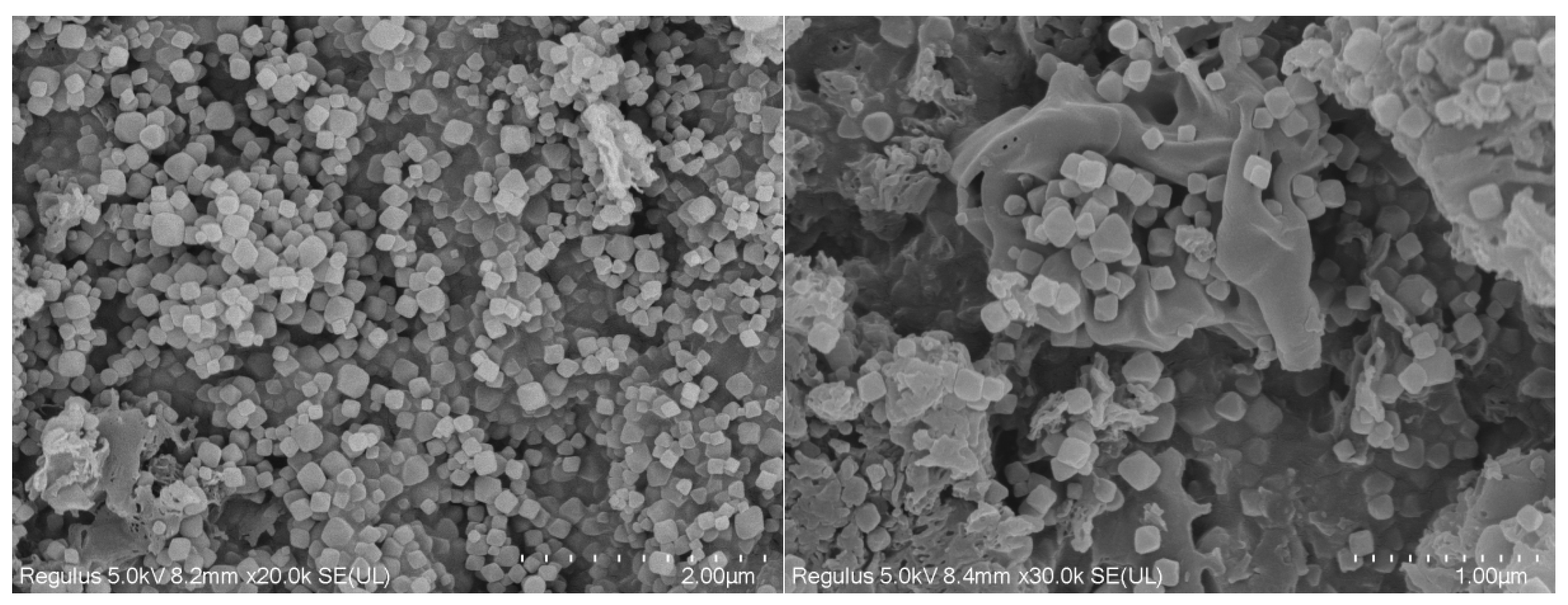
Figure 1.
The SEM image of the UG 6:4 represented by the MOF.
Figure 1.
The SEM image of the UG 6:4 represented by the MOF.
The emergence of MOFs as a new type of framework material has propelled the development of adsorbent technology. In recent years, many materials with higher specific surface areas than traditional adsorbents have been developed, such as PCN-222, MIL-125, and UiO-66. In the synthesis of MOFs, organic ligands not only coordinate with metal nodes, but their remaining coordination sites can also interact with small molecule solvents, typically forming fragile bonds. Under special conditions, the small molecule solvents can be removed from the MOFs, leaving unsaturated coordination sites, thus endowing the MOF framework material with reactive alkaline and acidic sites that allow its application as basic catalysts or Lewis acids. The diversity of MOF structures is determined by the coordination capabilities of different metal ions or organic ligands, with the diversity of organic ligands being even richer, and their structures are also varied.
Moreover, the formation of MOFs is also influenced by various factors such as the ratio of materials, purity, and synthesis temperature. Therefore, MOFs produced under different synthesis conditions will have distinct internal structures. Using these properties, MOFs with specific functions can be prepared as needed. The primary characteristics of MOF materials include:
- A.
High specific surface area and pore volume: MOFs can achieve very high specific surface areas (over 1,000 square meters per gram), making them ideal materials for storage, separation, and catalytic reactions.
- B.
Structural diversity: By selecting different metal ions and organic linkers, MOFs with varied structures and functions can be synthesized to suit different application needs.
- C.
Adjustability: MOFs are designable, and their chemical functions can be modified through post-treatment methods (such as functionalization, doping, etc.) to achieve specific purposes.
- D.
Thermal stability and chemical stability: Some MOFs have good thermal stability and chemical stability, making them suitable for different chemical processes and environmental conditions.
Figure 2.
Summary of the high chemical stability of some representative MOFs.
Figure 2.
Summary of the high chemical stability of some representative MOFs.
2.2. Characteristics and Application of Graphite-Phase Carbon Nitride (g-C3N4)
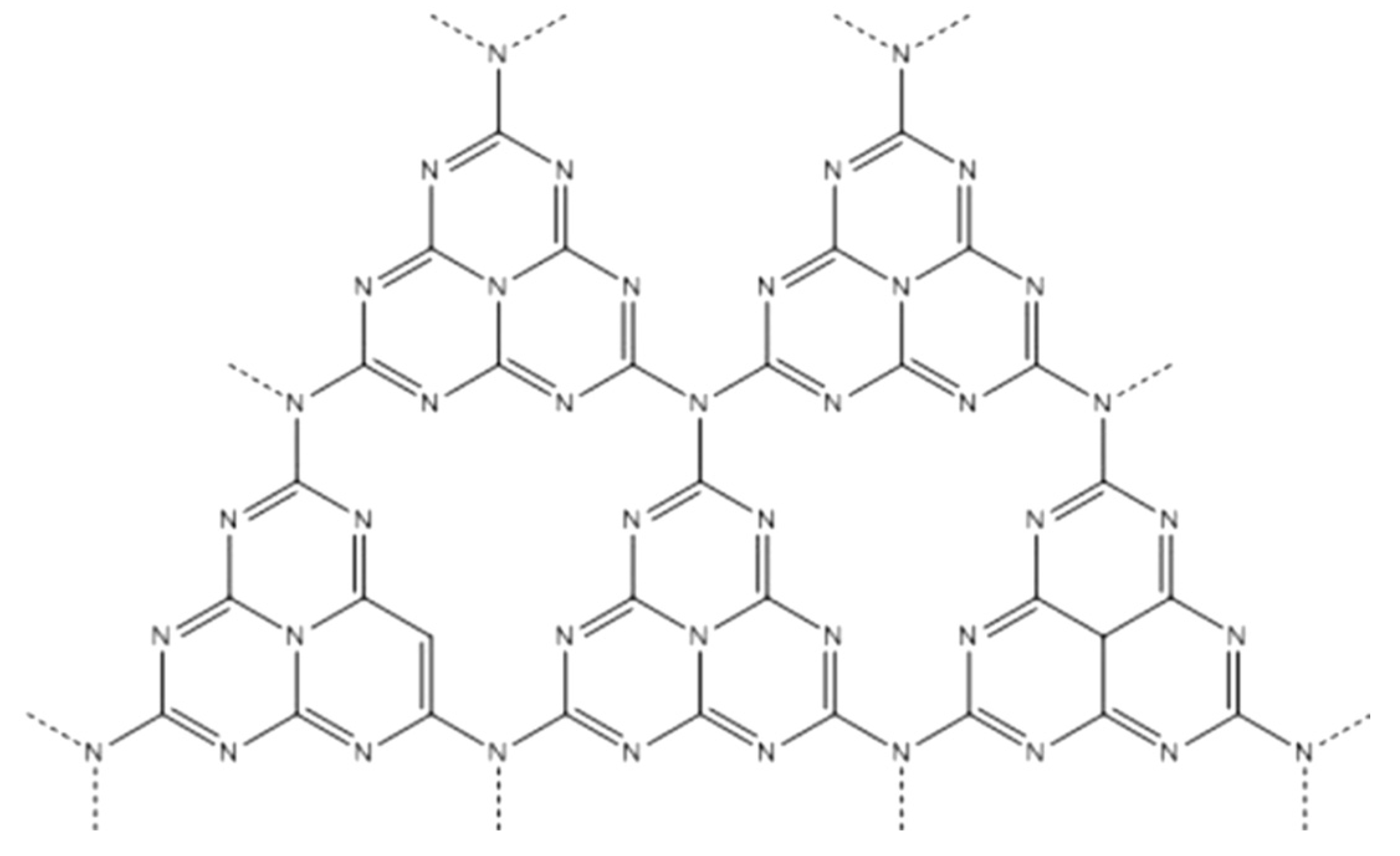
Graphitic carbon nitride (g-C3N4) is a two-dimensional covalent organic framework material composed of carbon and nitrogen. It features a graphitic layered structure with each carbon atom bridged by three nitrogen atoms, forming a three-dimensional hexagonal network. This material not only exhibits high stability and excellent thermoelectric properties but also possesses good photocatalytic and electrocatalytic characteristics, attracting widespread attention in various fields. g-C3N4 eliminates the use of traditional metal catalysts, providing a new option for green chemistry.
Figure 3.
Molecular configuration of g-C3N4.
Figure 3.
Molecular configuration of g-C3N4.
The main characteristics of g-C3N4 include:
- A.
Wide bandgap: The bandgap of g-C3N4 is about 2.7eV, which means it can utilize a part of visible light for photocatalytic reactions, making it one of the more active visible-light-driven photocatalysts.
- B.
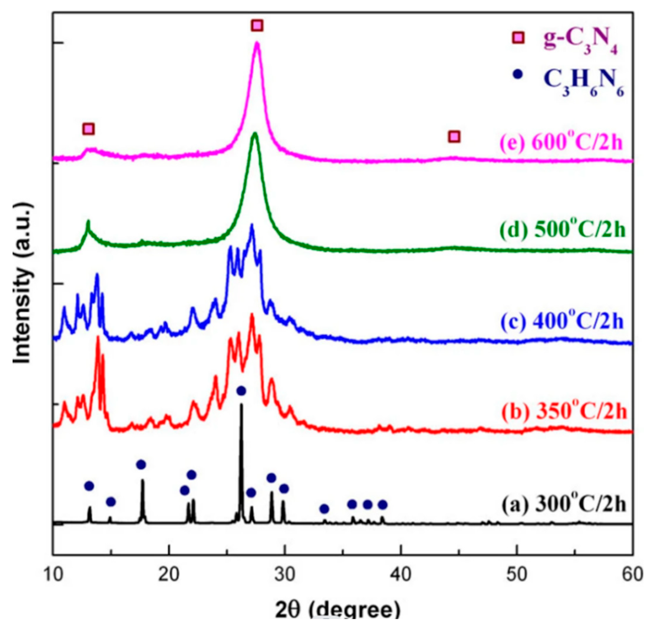
Good chemical and thermal stability: Due to its unique covalent structure, g-C3N4 exhibits good stability in air and common organic solvents (such as ethanol, acetaldehyde, etc.), and can withstand high temperatures. As shown in the diagram below, g-C3N4 still maintains a certain strength at 600°C, indicating its high temperature resistance.
Figure 4.
Plot of the g-C3N4 intensity with temperature.
Figure 4.
Plot of the g-C3N4 intensity with temperature.
- C.
Enhanced light absorption capability: By controlling the structure (e.g., high-temperature and high-pressure treatment) and doping with heteroatoms (such as P, S, B, etc.), its light absorption capacity can be further enhanced.
- D.
Good electron mobility and transmission characteristics: Suitable for use in electronic devices and materials.
- E.
High specific surface area: Can enhance the active sites of catalysis, improving catalytic efficiency.
- F.
Non-metal catalyst: As a non-metal material, g-C3N4 helps reduce reliance on rare metal resources.
Applications of g-C3N4 include:
- A.
Photocatalysis: g-C3N4 can be used in photocatalytic processes such as water splitting for hydrogen production, degradation of organic pollutants, CO2 reduction, etc.
- B.
Electrocatalysis: Shows potential catalytic activity in oxygen reduction reaction (ORR), oxygen evolution reaction (OER), hydrogen evolution reaction (HER), etc.
- C.
Separation materials: Used as adsorbents or membrane materials for gas separation, water treatment, etc.
- D.
Electrochemical sensors: Used to construct sensors for sensitive detection of specific compounds.
- E.
Energy storage: Used as materials for supercapacitors or battery electrodes, improving energy storage performance.
- F.
Biomedical: Also shows potential for applications in antimicrobial, photodynamic therapy, and drug delivery.
2.3. Unique Structure and Properties of the UiO-66 / g-C3N4 Composite Catalyst
The UiO-66/g-C3N4 composite catalyst combines the characteristics of the Metal-Organic Framework (MOF) UiO-66 and graphitic Carbon Nitride (g-C3N4), forming a novel catalytic material with a unique structure and properties. UiO-66, a widely studied Zr-based MOF, is composed of Zr6O4(OH)4 clusters and organic ligands (usually terephthalic acid). It possesses a high surface area, high thermal stability, and good chemical stability. g-C3N4, on the other hand, is a non-metal two-dimensional photocatalyst with a moderate bandgap and unique electronic properties.
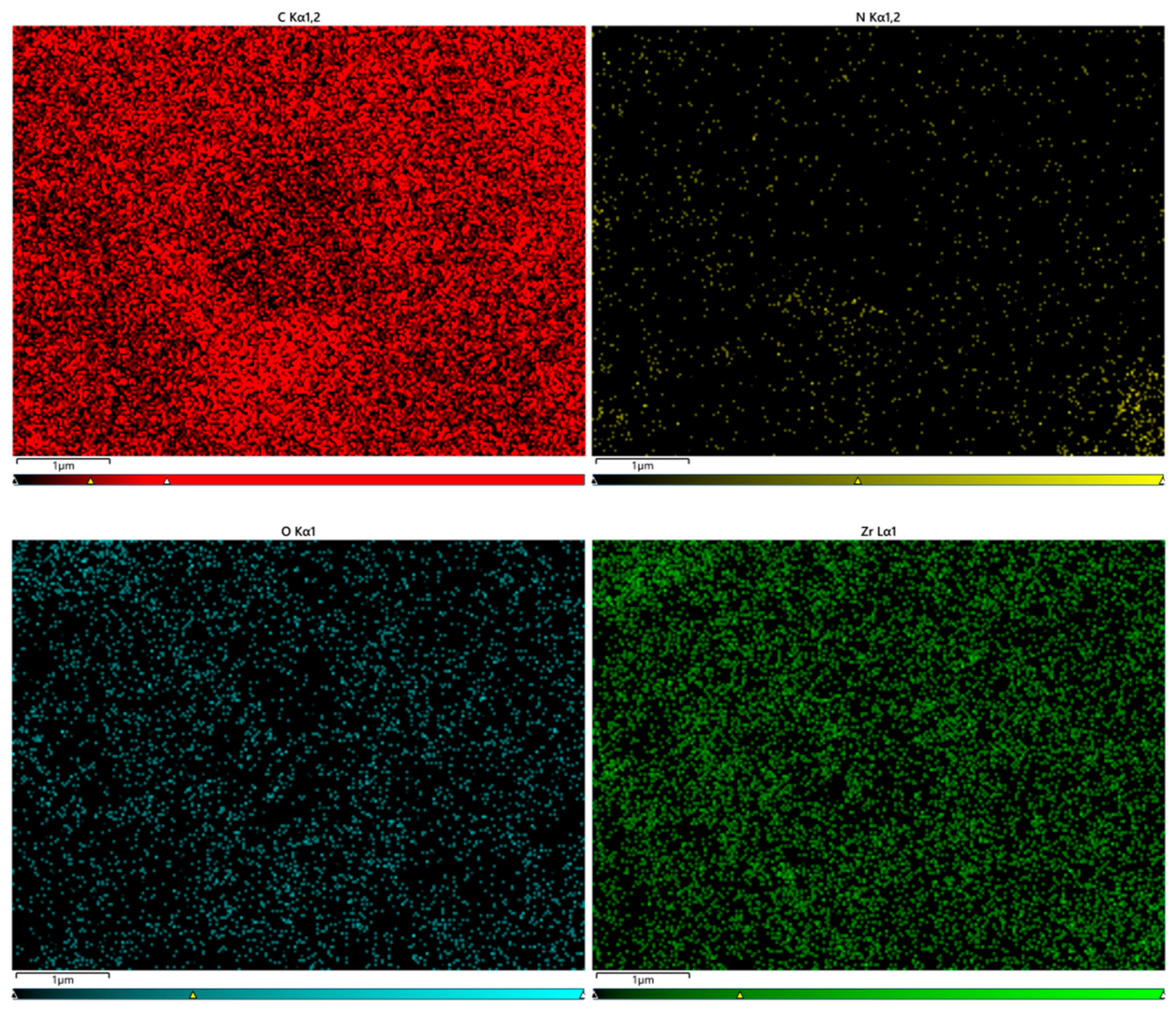
Figure 5.
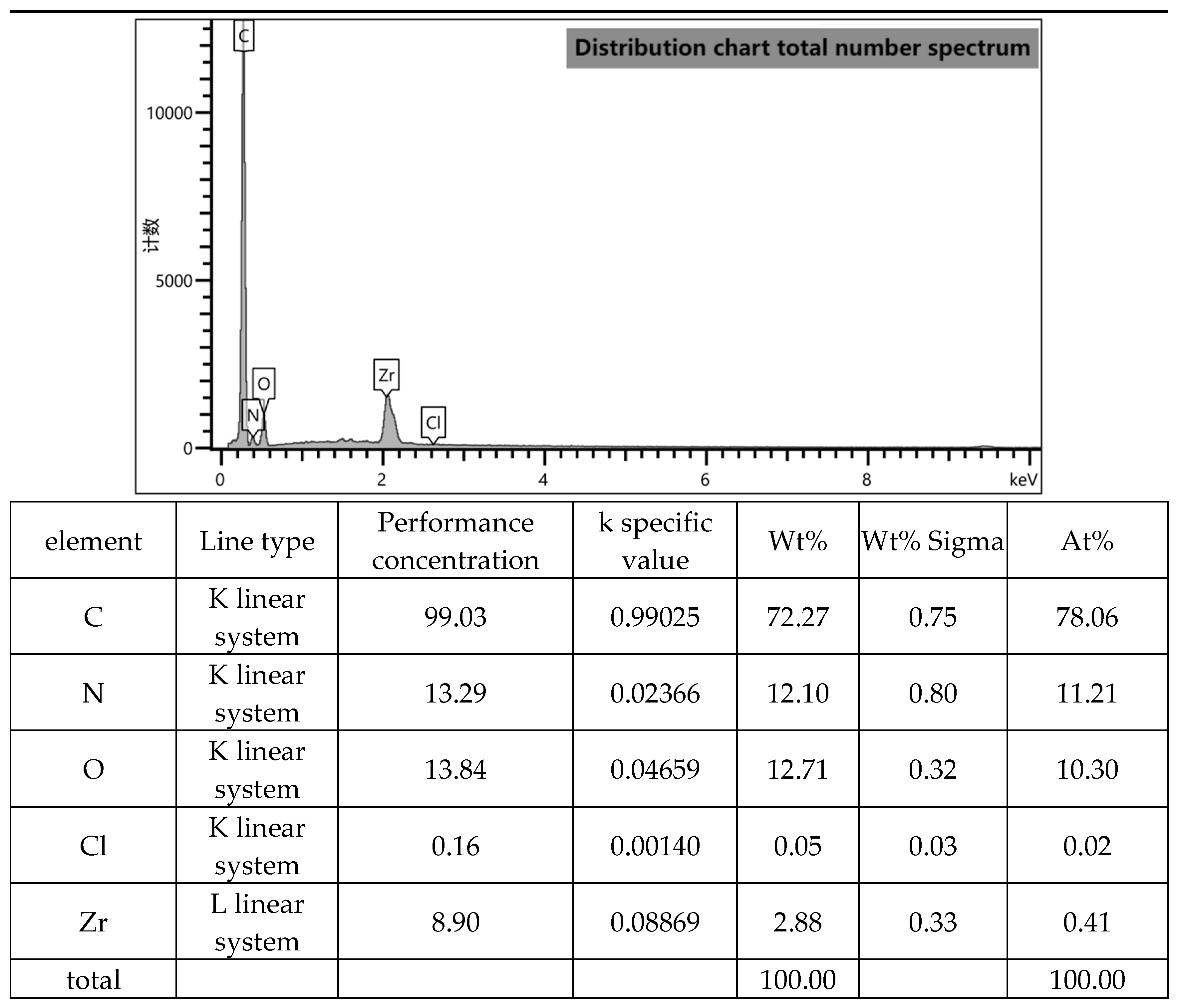
The EDS energy profile analysis of UG 6:4.
Figure 5.
The EDS energy profile analysis of UG 6:4.
Figure 6.
Total number of distribution graphs.
Figure 6.
Total number of distribution graphs.
Combining UiO-66 with g-C3N4 results in a composite catalyst with the following unique structural and performance characteristics:
- A.
Enhanced photocatalytic efficiency and light response range: The UiO-66/g-C3N4 composite catalyst, due to the integration of g-C3N4's visible light absorption capability, can utilize a broader spectrum of sunlight. At the same time, the high surface area of the MOF provides a large number of active catalytic sites, significantly improving catalytic efficiency.
- B.
Optimized electronic properties: Due to the electron-accepting properties of UiO-66 and the electron-donating properties of g-C3N4, a favorable heterojunction is formed, facilitating the effective separation and transfer of photogenerated charges, reducing recombination, and enhancing catalytic performance.
- C.
Improved structural stability: The inclusion of UiO-66 helps enhance the structural stability of g-C3N4, inhibiting deformation or decomposition under high temperature or hydrothermal conditions.
- D.
Tunable adsorption properties: UiO-66 features an adjustable porous structure and hydrophilicity/hydrophobicity, which can be customized through chemical modifications to tailor the adsorption properties for specific molecules, thereby improving catalytic performance.
- E.
Multifunctionality: This composite catalyst can be used not only in traditional photocatalytic reactions such as water splitting for hydrogen production and degradation of organic dyes, but also in applications like electrocatalysis, electrochemical sensors, and as an adsorbent, among others.
Due to these attributes, the UiO-66/g-C3N4 composite catalyst shows great potential in areas such as environmental management (like photodegradation of organic pollutants), energy conversion and storage (such as water splitting for hydrogen production), and chemical sensing. However, the exact structure and performance of this composite material are influenced by the preparation process (such as synthesis methods, ratios, and post-treatment conditions), thus detailed characterization and optimization are needed in practical applications.
3. Experiment
3.1. UG 6:4 Phosphorus Adsorption Influence Factors Experiment
Dissolve 0.8787 g of anhydrous dipotassium phosphate (KH
2PO
4) in deionized water, then transfer it to a 1 L volumetric flask, and dilute the solution to the mark to prepare a phosphate stock solution of 200 mg P/L. By diluting this stock solution, prepare phosphate solutions of desired concentrations for experiments. Take 100 mL of the phosphate solution in a conical flask, add an appropriate amount of adsorbent material, and adjust the pH of the reaction solution to optimum using NaOH and HCl solutions. Place it in an incubator shaker set at 200 rpm, and conduct the adsorption experiment at a specific environmental temperature for 10 hours. After the experiment, take a sample, filter it through a 0.22 μm filter, and measure it. (Measurement method: Treat the phosphorus-containing sample with HNO
3 and H
2SO
4 (25 mL each), convert phosphorus to H
3PO
4, then add ammonium molybdate in an HNO
3 medium, and fully react to form a yellow precipitate of ammonium phosphomolybdate. Filter the precipitate, wash it with water, and then dissolve it in a certain quantity of excess 1 mol/L NaOH standard solution (record the volume of NaOH). The excess NaOH is titrated back to the endpoint where phenolphthalein just fades (pH ≈8) with HNO
3 standard solution. The stoichiometric ratio of phosphorus to NaOH is 1:24. From this, the amount of phosphorus in the sample can be calculated.) From the measured inorganic phosphorus concentration, calculate the adsorption capacity. All batch adsorption experiment results are the average of three repeated measurements. Phosphorus adsorption capacity is calculated using the following formula:
3.1.1. Experiments on the Effect of pH Size on the Adsorption Capacity
In the formula, qe (mg/g) represents the adsorption capacity, C0 (mg/L) is the initial phosphate concentration, Ce (mg/L) is the equilibrium phosphate concentration, V (L) is the volume of the solution, and m (g) is the amount of adsorbent added. In the experiment on the effect of the initial pH value of the solution on the phosphate adsorption performance, a phosphate solution with an initial concentration of 20 mg/L was prepared by diluting the phosphate stock solution. 100 mL of the phosphate solution was taken in a conical flask, and the pH value of the reaction solution was adjusted to within the range of 1-10 using appropriate concentrations of NaOH and HCl solutions. 0.02 g of UiO-66/g-C3N4 was added as the adsorbent material. It was placed in a constant temperature shaker at 200 rpm and conducted an adsorption experiment for 10 h at an ambient temperature of 25 ℃.
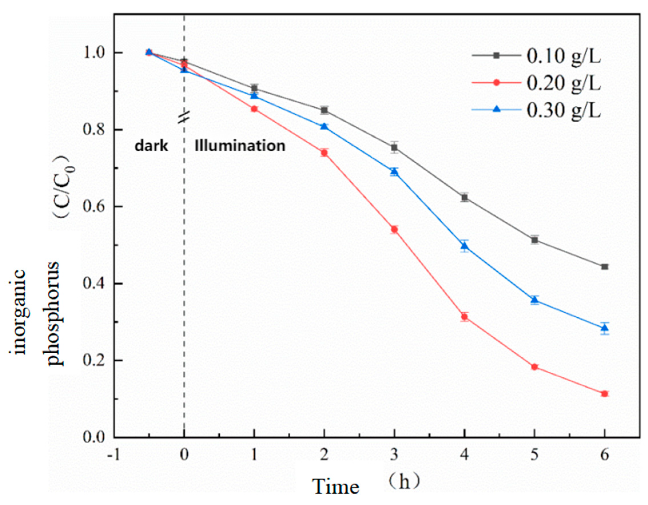
Before the photocatalytic reaction, a 30-minute dark adsorption showed that the adsorption capacity of the catalyst for phosphate salts increased with the addition of the catalyst, indicating that UG 6:4 has a certain adsorption capacity for inorganic phosphorus. Preliminary experimental results showed that in the absence of a catalyst, inorganic phosphorus was almost unchanged. However, as the amount of photocatalyst increased from 0.10 g/L to 0.20 g/L, the adsorption efficiency significantly increased from 55.7% to 88.7%.
Figure 7.
Effect of UG 6:4 dosage on the effect of photocatalytic phosphorus adsorption.
Figure 7.
Effect of UG 6:4 dosage on the effect of photocatalytic phosphorus adsorption.
3.1.2. The Effect of Anionic Strength on the Adsorption in the Experiments
After the experiment was finished, samples were taken, filtered through a 0.22 μm filter, and measured to determine the optimal pH value under the best adsorption capacity. In the experiment on the effect of the presence of coexisting anion intensity on adsorption, with the initial phosphate concentration of 20 mg/L, the solution was adjusted to the optimal pH value. Different concentrations (1 mM, 10 mM, 100 mM) of sodium chloride (NaCl), sodium sulfate (Na2SO4), sodium carbonate (Na2CO3), and sodium nitrate (NaNO3) were added to the phosphate solution to study the effect of Cl-, SO4 2-, CO3 2-, NO3- on adsorption.
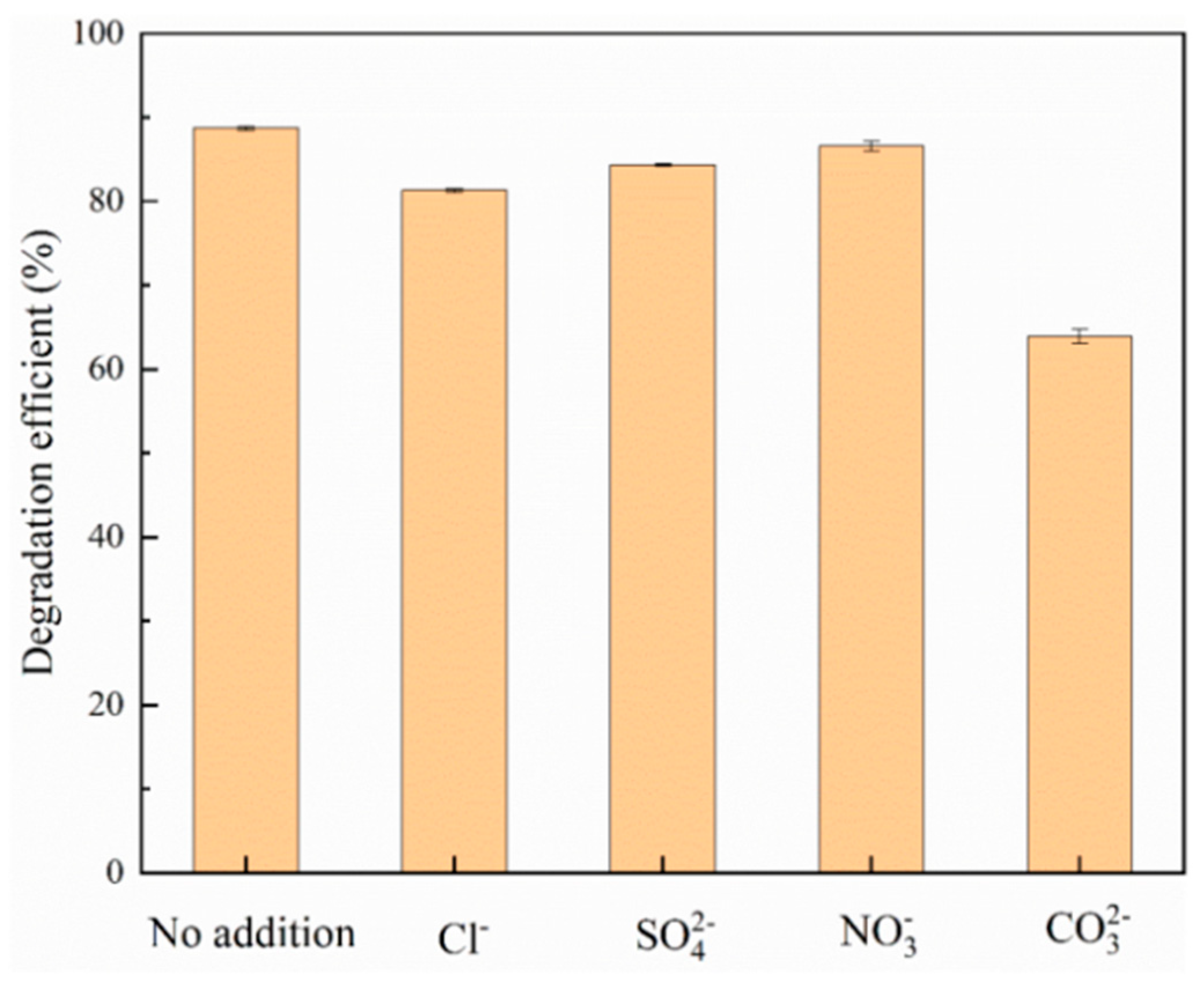
Inorganic anions reduce the degradation potential of photocatalytic treatment systems by capturing oxidizing substances that adsorb inorganic phosphorus in photocatalysts. To this end, this study added sodium chloride (NaCl), sodium sulfate (Na2SO4), sodium nitrate (NaNO3), and sodium carbonate (Na2CO3) to the reactor to reveal the effects of Cl-, SO4 2-,NO3-, and CO3 2- ions on the adsorption efficiency of inorganic phosphorus.
Figure 8.
Effect of different coexisting anions on the photocatalytic adsorption of inorganic phosphorus.
Figure 8.
Effect of different coexisting anions on the photocatalytic adsorption of inorganic phosphorus.
3.1.3. Adsorption Isotherm Experiments
The specific experimental steps for the adsorption isotherm are as follows: By diluting the previously prepared phosphate stock solution, initial solutions with phosphate concentrations of 5, 10, 20, 30, 40, 50, 75, 100, 125, 150 mg/L are prepared. Then, 100 mL of each solution is taken in a conical flask, and the reaction solution is adjusted to the optimal pH value (6). After that, 0.02 g of UG 6:4 adsorbent is evenly mixed in, and the mixture is placed in a constant temperature oscillation box at 200 rpm. The adsorption experiment is carried out under the condition of 25°C for 10h. After the experiment is finished, samples are taken, filtered through a 0.22 µm filter, and then measured. The adsorption capacity is calculated based on the measured inorganic phosphorus concentration. Following the same steps, repeat the experiment at 15°C, 35°C, and perform isotherm fitting and analysis on all experimental data.
The isotherm model reflects the relationship between the concentration of the adsorbate and the adsorption capacity of the adsorbent in the equilibrium state, which is essential for a deep understanding of the adsorption behavior. To study the adsorption mechanism of UG 6:4 in the process of adsorbing phosphates, the Langmuir and Freundlich adsorption isotherm models were used to evaluate the phosphate adsorption capacity of UG 6:4. The equations of the two models are as follows:
In the formula, qe (mg/g) represents the equilibrium adsorption capacity, qm (mg/L) represents the theoretical maximum adsorption capacity, Ce (mg/L) is the phosphorus concentration at adsorption equilibrium, Kf (L/mg) and Kl () are the adsorption constants for the Langmuir and Freundlich models, respectively. "n" is related to the adsorption strength; when 1/n is greater than 2, adsorption is difficult to occur; when the 1/n value is between 0.1 and 0.5, adsorption is likely to occur.
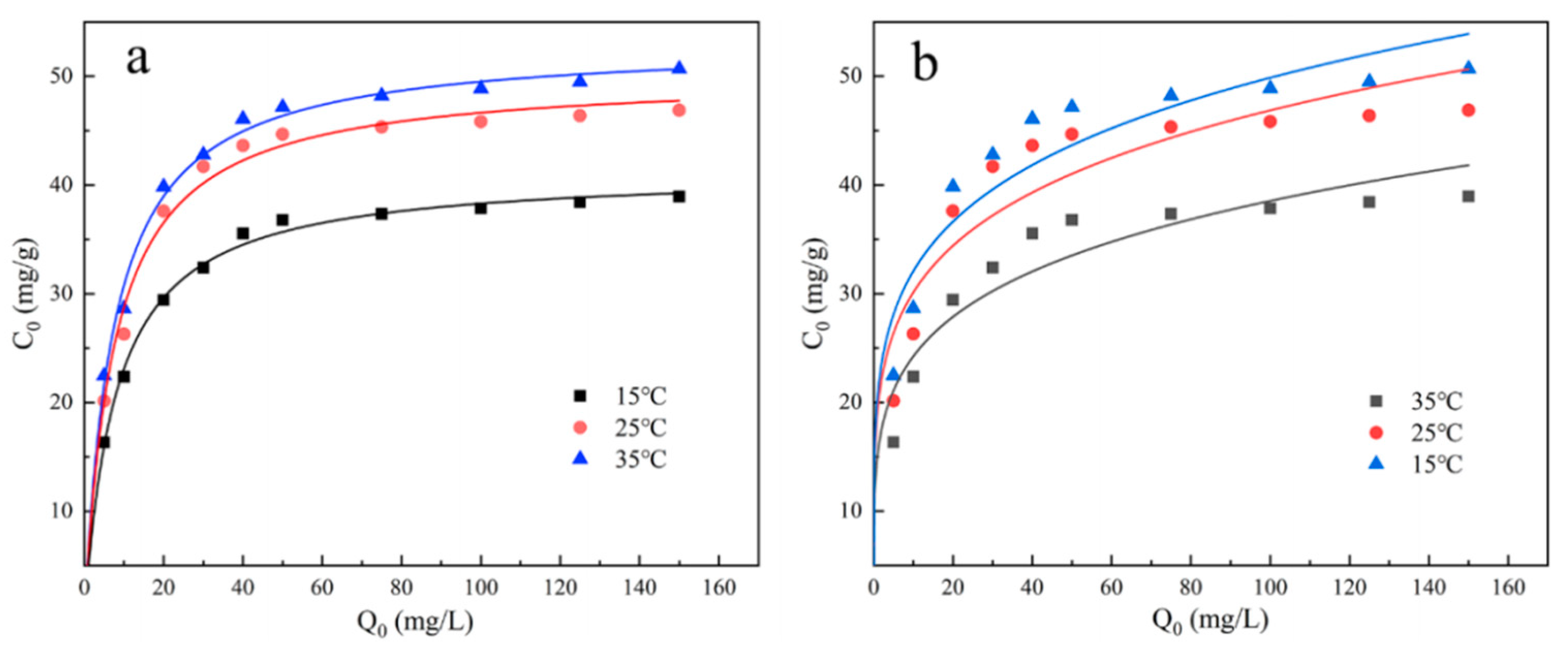
The isothermal model reflects the relationship between the concentration of the adsorbate and the adsorption capacity of the adsorbent in a state of equilibrium. The fitting results of the two adsorption isotherm models, Langmuir and Freundlich, are shown in the figure. It is clear from the figure that, within the two adsorption isotherms, as the temperature gradually increases, the adsorption amount of phosphate also gradually increases, indicating that the adsorption process of phosphate by UG 6:4 is an endothermic reaction. The correlation coefficient (R2) of the Langmuir isotherm model fitting is higher than that of the Freundlich model fitting. At 25°C, and at a pH of 6, the maximum phosphate adsorption capacity reaches up to 50.12 mg/g.
Figure 9.
UG 6:4 Langmuir (a) and Freundlich (b) isotherms of phosphate adsorption.
Figure 9.
UG 6:4 Langmuir (a) and Freundlich (b) isotherms of phosphate adsorption.
3.1.4. Of the Adsorption Kinetic Experiments
The experimental steps for adsorption kinetics are as follows: Dilute the pre-prepared phosphate stock solution to prepare 16 portions of 20 mg/L, 100 ml phosphate solutions in conical flasks. Adjust the solution to the optimum pH value, add 0.02 g of UG 6:4 adsorbent, and mix evenly. Place it in an incubator at 25°C and 200 rpm for 10 h. Take a small amount of the supernatant at 5, 10, 20, 30, 60, 90, 120, 150, 180, 240, 300, 360, 420, 480, 540, and 600 min, filter it through a 0.22 filter head for measurement, and calculate the adsorption capacity based on the concentration of inorganic phosphorus in the measured solution.
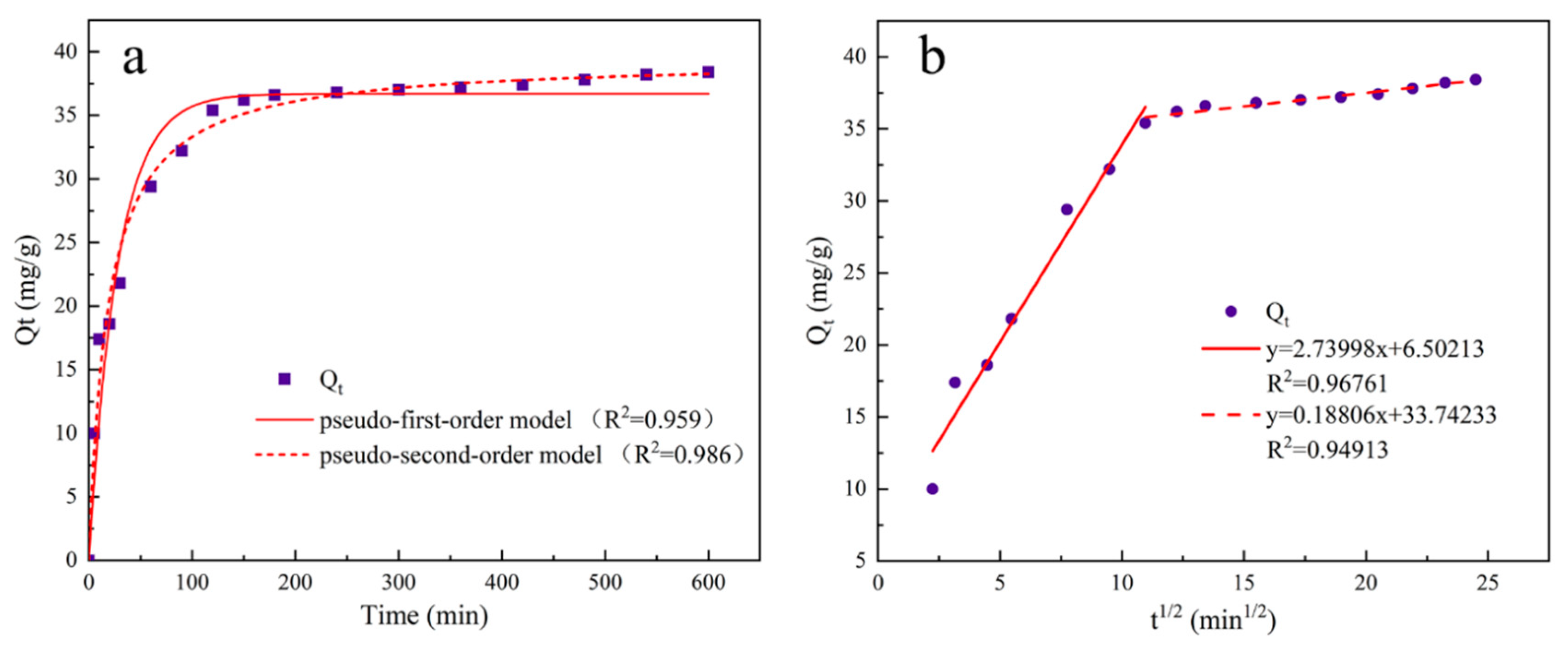
To study the adsorption pattern of UG 6:4 in the phosphate adsorption process, three kinetic models were used: pseudo-first-order, pseudo-second-order kinetics, and intraparticle diffusion models. The three kinetic rate equations are as follows:
In the formula, qt (mg/g) represents the amount of phosphate adsorbed over time t, qe (mg/g) is the amount of phosphate adsorbed at equilibrium; t is the adsorption time, k1 (min-1) is the pseudo-first-order rate constant, k2(min-1) is the pseudo-second-order rate constant, kip (mg/g/min1/2) is the rate constant of the intraparticle diffusion kinetics model; C is a constant related to the boundary layer thickness.
Figure 10.
The adsorption kinetic model and intra-particle diffusion model of UG 6:4 adsorbed phosphate.
Figure 10.
The adsorption kinetic model and intra-particle diffusion model of UG 6:4 adsorbed phosphate.
3.1.5. Urban Sewage Verification Experiment
To verify the practical application effect of UG 6:4 in situ adsorption of inorganic phosphorus by degradation of organic phosphorus pollutants, it was applied to actual phosphorus-containing wastewater, which was sampled from Shangtang River and industrial wastewater raw water. The optimal dosage of the composite material was added to 100 ml of the raw water. After 30 minutes of adsorption in the dark, the UV light was turned on to start the reaction. After the photocatalytic reaction ended, samples were taken to measure the concentration of inorganic phosphorus in the reaction liquid, and the removal rate of phosphorus-containing wastewater was calculated using the following formula:
In the formula, C0 (mg/L) represents the total phosphorus concentration, C1 (mg/L) indicates the inorganic phosphorus concentration in the raw water, C2 (mg/L) is the total phosphorus concentration in the solution after the photocatalytic reaction, C3 (mg/L) is the inorganic phosphorus concentration in the solution after the photocatalytic reaction.
3.2. UG 6:4 on Air Xylene Degradation Experiment
3.2.1. Effects of Different Loads on the Degradation of Xylene
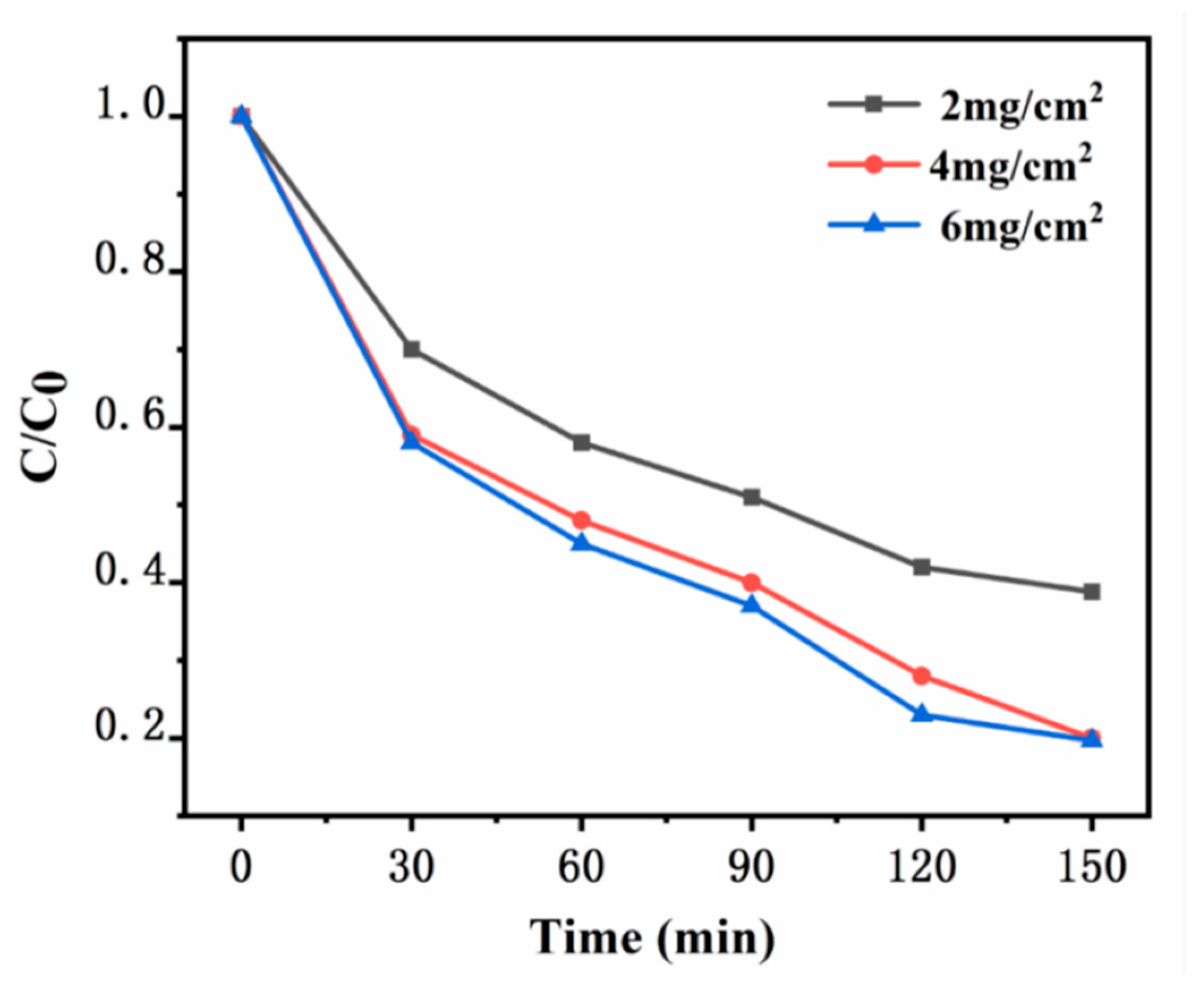
The xylene degradation experiment is conducted in a sealed reaction chamber. A quartz glass plate measuring 10 cm × 10 cm is used, with varying amounts of synthetic catalyst UG 6:4 coated on the glass surface, forming catalyst loadings of 2 mg/cm², 4 mg/cm², and 6 mg/cm². The temperature is maintained at room temperature, and the initial xylene concentration is constant at 20 ppm. The photocatalytic degradation of xylene under a 100 W daylight lamp is conducted to preliminarily explore the optimal amount of catalyst. The application and mechanism analysis of photocatalysis are shown in Figures. When the loading of UG 6:4 is 2 mg/cm², the degradation efficiency of xylene is relatively low, with only 61.2% degraded within 150 minutes. As the catalyst loading increases to 4 mg/cm², a significant improvement in the degradation efficiency of xylene is observed, reaching 80%. Further increasing the catalyst loading to 6 mg/cm², the improvement in xylene degradation efficiency is minimal, reaching 81.3%. When the catalyst loading continues to increase to 6 mg/cm², there is almost no improvement in the degradation efficiency of xylene.
Figure 11.
Degradation profiles of xylene with different catalyst loads.
Figure 11.
Degradation profiles of xylene with different catalyst loads.
3.2.2. Effect of the Initial Concentration of Xylene on the Degradation Performance
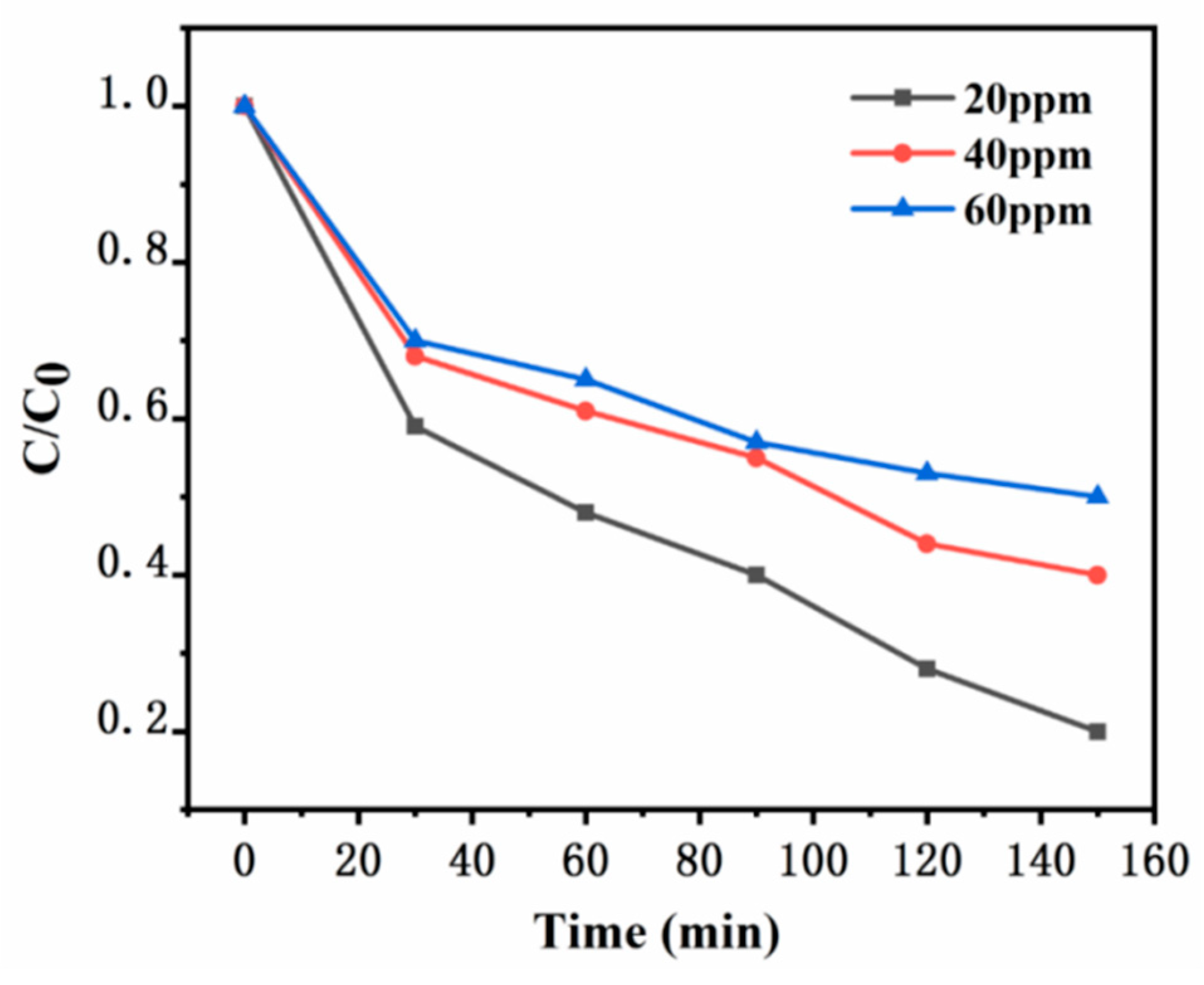
In the experiment, while keeping other experimental conditions consistent, different initial concentrations of xylene gas were added into a sealed reaction apparatus, specifically at 20 ppm, 40 ppm, and 60 ppm. The temperature was maintained at room temperature. Quartz glass plates measuring 10 cm by 10 cm were used, and the photocatalytic degradation of xylene was carried out under the illumination of a 100W daylight lamp to study the effect of the initial concentration of xylene gas on the degradation performance. It can be clearly seen from
Figure 12 that the prepared UG 6:4 catalyst exhibited certain degradation performance for xylene gas at different concentrations. It is evident that as the initial concentration of xylene increased, the degradation efficiency gradually decreased. Under the conditions of this experiment, when the initial concentration of xylene was 20 ppm, the degradation efficiency of the synthesized catalyst UG 6:4 was the highest.
Figure 12.
Effect of different initial concentrations of xylene on the degradation performance.
Figure 12.
Effect of different initial concentrations of xylene on the degradation performance.
4. Application
Application of UiO-66/g-C3N4 in catalytic decomposition of organic pollutants.With global development, agricultural merchandise has been modernized. The pollution of soil and water resources by pesticide residues is imminent. However, finding an efficient, rapid, and economical solution to solve the problem of catalytic organic degradation still faces great challenges.UiO-66/g-C3N4 graphite phase carbon nitride.
We produce a wide range of catalysts with excellent activity and stability.The low cost ,high efficiency and recyclability of the catalyst practice the concept of enviromental protection from the starting point. As mention above, UiO-66/g-C3N4 catalysts fit the needs of goverments and citizens to adress the pollution.
In particular, benefitting from the adjustable pores of UiO-66 and the photoelectric properties of g-C3N4, the separation of electron-hole pairs is enhanced, while the material's high adsorbability promotes the REDOX reaction collaboratively. Thus the product has outstanding performance in photocatalysis. According to the experiment results , the degradation efficiency of U:G 6:4 for DDVP was up to 88.7% ,which is significantly improved compared with the single UiO-66 catalytic effect, and the degradation efficiency of DMB was up to 80% when the U:G 6:4 loading capacity was 4mg/cm². Relying on the excellent photocatalytic performence and structual characteristics of the material. It has important value in reducing VOCs emission, and has good degradation effect on nitride, sulfide and xylene. Because this product is photocatalyzed, the cost is low. It can be integrated into environmental remediation facilities as a paint application and integrated into the environmental governance system to solve urban haze and industrial emissions.
In summary, the advantages compared with traditional methods are as follows:
- A.
Efficient degradation:Due to the structural synthesis of n-n heterojunction, the composite has excellent performance in visible light response and photogenerated electron-hole separation ability. Therefore, it shows higher photocatalytic activity and degradation efficiency than traditional catalysts in pesticide conversion and air purification reactions.
- B.
Environmentally friendly:In the process of photocatalysis, its catalyst can be carried out at room temperature and pressure, converting organic pollutants into harmless substances, reducing the negative impact on environmental pollution and ecosystem.
- C.
Reusable:Because the composite material has good stability, it can be reused many times, reducing the use cost and improving the economic efficiency of operation.
- D.
Wide range of applications: the composite material can not only convert a variety of harmful substances, but also absorb small pollutants in the air, such as PM2.5.
- E.
Resource conservation:The materials used in the composite are cheap and readily available, and the concept of environmental protection is implemented from the source.
5. Summary and Outlook
The UiO-66/g-C
3N
4 composite catalyst combines the characteristics of the Metal-Organic Framework (MOF) UiO-66 and graphitic Carbon Nitride (g-C
3N
4)[
11], forming a new catalytic material with unique structure and performance. The advent of MOFs as a new type of framework material has propelled the development of adsorbent technology, and in recent years, many materials with higher specific surface areas than traditional adsorbents, such as PCN-222, MIL-125, and UiO-66, have been developed. In the synthesis of MOFs, organic ligands are coordinated with metal nodes, and their remaining coordination sites can also form coordination relationships with small molecule solvents, which are usually relatively fragile. Under certain conditions, small molecule solvents can be removed from MOFs, leaving unsaturated coordination sites, thus providing MOFs with reactive alkaline and acidic sites, enabling their application as alkaline catalysts or Lewis acids. The diversity of MOF structures is determined by the coordination capabilities of different metal ions or organic ligands, with a richer diversity of organic ligands, and their structures are also diverse. Graphitic Carbon Nitride (g-C
3N
4) is a two-dimensional covalent organic framework material composed of carbon and nitrogen. It has a graphite-like layered structure, with each carbon atom bridged by three nitrogen atoms, forming a three-dimensional hexagonal network. This material not only has high stability, excellent thermoelectric properties, but also has good photocatalytic and electrocatalytic characteristics, making it widely noticed in many fields. g-C
3N
4 abandons the use of traditional metal catalysts, offering a new choice for green chemistry. When these two materials are combined into a composite catalyst, the aim is to incorporate each other's advantages, such as the high specific surface area and porosity of MOF combined with the photocatalytic activity of g-C
3N
4, thereby enhancing catalytic efficiency and stability.
In the inorganic phosphophotocatalytic adsorption experiment, preliminary results indicated thatInorganic phosphorus salts do not adsorunder UV irradiation. To achieve adsorption-desorption equilibrium between the catalyst and inorganic phosphorus, it was stirred in the dark for 30 minutes before turning on UV irradiation for 6 hours. Original UiO-66 had little effect on the degradation of inorganic phosphorus, with a degradation efficiency of only 23.3%, while g-C3N4 had almost no degradation effect on inorganic phosphorus After calcination of UiO-66 and g-C3N4, composite materials prepared with different X:Y ratios all showed enhanced photocatalytic degradation efficiency compared to the raw materials alone, with UG 6:4 reaching the highest degradation efficiency of 88.7%, and UG 4:6, UG 5:5, UG 7:3 having degradation efficiencies of 54.7%, 68.1%, and 71.3%, respectively. In the recycling experiment, the UG 6:4 material still achieved a Adsorption efficiency of 37.3% for the difficult-to-adsorption of inorganic phosphate after five cycles of reuse. In the air purification experiment, it was proven to have good degradation capacity for xylene gas. This fully demonstrates that UiO-66/g-C3N4, due to its unique properties, has great potential in handling soil organic pollutants, especially photosensitive pollutants. These properties include: its high specific surface area providing more activation points, the crystalline structure providing better photocatalytic stability, and the heterogeneous structure effectively enhancing the electron-hole separation efficiency, thereby accelerating the degradation rate of pollutants. Moreover, the adjustability and multifunctionality of MOFs also provide possibilities for selective degradation of specific pesticides.
The significant advantages of the UiO-66/g-C3N4 catalyst in purifying air and soil provide potential for integration with other technologies, such as:
- A.
Nanotechnology: Integrating UiO-66/g-C3N4 with nanotechnology could further improve catalytic efficiency and surface activity, making pollutant decomposition more effective. This combination could be used to manufacture smaller, more efficient air purifiers and soil purification devices.
- B.
Solar technology: Combining the UiO-66/g-C3N4 catalyst with solar technology could develop eco-friendly purification systems using renewable energy. For example, a solar-powered photocatalytic purification system would be energy-saving, environmentally friendly, and usable in off-grid areas.
- C.
Membrane technology: Combined with membrane separation technology, devices that integrate catalytic purification and physical separation could be designed, allowing more precise treatment of contaminants in air and water.
- D.
3D Printing Technology: Through 3D printing technology, the structure of catalyst carriers can be customized, such as manufacturing carriers with specific shapes and pore structures to maximize the contact area and activity of the catalyst.
However, there are still some challenges at the economic, technical, and environmental levels. Economically, sustainable development needs to consider the efficiency of resource use in production, the introduction of circular economy concepts, etc. By improving resource utilization efficiency, projects can not only reduce production costs but also minimize environmental impact, achieving a win-win for economic and environmental benefits. Technically, the stability and regenerability of the catalyst need further study to ensure long-term operation and efficient use. The promotion and application of the technology need to consider the adaptability to different regions and environmental conditions, which may require customized adjustments to the catalyst. Additionally, some engineering and equipment issues may be involved in the application process, which need comprehensive consideration. Environmentally, the production and application of the catalyst may produce some by-products or waste, and effective measures need to be taken to prevent negative impacts on the environment. The promotion and application of the technology also need to consider the adaptability to different regions and climates to ensure the best effect in different environments.
In the future, the development of new soil and air purification products based on UiO-66/g-C3N4 catalysts should focus on continuous improvement and technological iteration upgrades. This includes optimizing material performance to improve pollutant purification capabilities, expanding application fields to industrial gas purification and improving indoor air quality, system integration productization, advancing modular and standardized design, technology upgrades introducing high-end analytical technologies such as machine learning, combining nanotechnology and bioengineering for innovation, to enhance environmental performance, while actively responding to environmental protection and sustainable development needs.
6. Innovation Points and Deficiencies
6.1. Innovation Points
SEM cold field electron microscope was used to photograph the product, advanced laboratory was used for catalytic adsorption experiments, and Matlab and origin software were used for drawing
6.2. Deficiencies
Insufficient number of experimental groups to precisely control pH et al
Acknowledgment
Materials.
References
- Zhang Xiaolong. Preparation and supercapacitor performance of cobalt / nickel metal organic framework and its derivatives [D]. And China University of Mining and Technology, 2022. [CrossRef]
- Long Lin. Preparation of UiO-66 / g-C3N4 composites and their photocatalytic properties [D]. Changchun University of Science and Technology, 2021. [CrossRef]
- Chen Wei. GC for simultaneous detection of six organPP residues in soil [J]. Chemical Engineer, 2023,37(06):42-44. [CrossRef]
- X. F.Lu,P.Q.Liao,J.W.Wang,J.X.Wu,X.W.Chen,C.T.He,J.P.Zhang,G.R. Li and X.M.Chen,J.Am.Chem.Soc., 2016, 138, 8336–8339.
- C. Heering,I.Boldog,V.Vasylyeva,J.Sanchiz and C. Janiak,CrystEngComm, 2013, 15, 9757–9768.
- L. Liang,C.Liu,F.Jiang,Q.Chen,L.Zhang,H.Xue, H.-L.Jiang, J. Qian, D.Yuan and M. Hong, Nat. Commun., 2017, 8, 1233.
- Y. Chen, B. Wang, X. Wang, L.-H. Xie, J. Li, Y. Xie and J.-R. Li, ACS Appl. Mater. Interfaces, 2017, 9, 27027–27035.
- Z. -R. Jiang, J. Ge, Y.-X. Zhou, Z. U. Wang, D. Chen, S.-H. Yu and H.-L. Jiang, NPG Asia Mater., 2016, 8, e253.
- V. Colombo, S. Galli, H. J. Choi, G. D. Han, A. Maspero, G. Palmisano, N.Masciocchi and J. R.Long,Chem. Sci., 2011, 2, 1311–1319.
- K.Wang, X.-L. Lv, D. Feng, J. Li, S. Chen,J. Sun,L.Song, Y. Xie,J.-R.Li and H.-C.Zhou,J.Am. Chem. Soc., 2016, 138, 914–919. [Google Scholar] [CrossRef] [PubMed]
- Zhu Tianzhe. Preparation of the Z-type BiVO4 / rGO / g-C3N4 photocatalyst and its visible-light photocatalytic properties [D]. Tianjin Polytechnic University, 2021. [CrossRef]
|
Disclaimer/Publisher’s Note: The statements, opinions and data contained in all publications are solely those of the individual author(s) and contributor(s) and not of MDPI and/or the editor(s). MDPI and/or the editor(s) disclaim responsibility for any injury to people or property resulting from any ideas, methods, instructions or products referred to in the content. |
© 2024 by the authors. Licensee MDPI, Basel, Switzerland. This article is an open access article distributed under the terms and conditions of the Creative Commons Attribution (CC BY) license (https://creativecommons.org/licenses/by/4.0/).
