Preprint
Article

Influence of Cement Thickness on Stress Distribution for Two Dental Implants Restored With Zirconia Crowns

Altmetrics

Downloads

114

Views

48

Comments

0

A peer-reviewed article of this preprint also exists.

Submitted:

11 June 2024

Posted:

11 June 2024

You are already at the latest version

Alerts
Abstract
The purpose of this finite element analysis (FEA) was to evaluate the stress experienced by both the prosthetic components and the bone in relation to varying cement thicknesses ranging from 20 to 60 μm, utilized in the attachment of a zirconia crown on a conometric cap. The study focused on two distinct types of implants (Cyroth and TAC, AoN Implants, Grisignano di Zocco, Italy) featuring a Morse cone connection. Detailed three-dimensional (3D) models were created to repre-sent the bone structure (cortical and trabecular) and the prosthetic components, encompassing the crown, cement, cap, abutment, and the implant. The two implants were placed in a 1.5 mm sub-crestal position and subjected to an inclined load of 200 N at 45° on the crown. The results re-vealed that an increase in cement thickness resulted in a reduction of von Mises stress on the cor-tical bone for both Cyroth and TAC implants, while the decrease in stress on the trabecular bone was relatively less pronounced. However, the TAC implant exhibited a higher stress field and de-formation in the apical area compared to the Cyroth implant. In summary, this study investigated the impact of cement thickness on stress transmission across prosthetic components and peri-implant tissues by means of FEA analysis, indicating that the 60 μm cement layer manifested higher stress values nearing the material strength limit.
Keywords: 
Subject: Medicine and Pharmacology  -   Dentistry and Oral Surgery

1. Introduction

Prosthetic restorations presently employ a range of materials. However, both metal-ceramic and double-layer all-ceramic restorations are susceptible to technical complications, primarily cohesive fracture of the veneering ceramic, commonly named chipping [1,2,3,4,5]. The monolithic design of all-ceramic crowns has been proposed as a means to mitigate mechanical issues owing to its exceptional anti-fracture mechanical properties and biocompatibility [6]. Monolithic zirconia has emerged as an alternative material to diminish the incidence of mechanical complications attributed to the fracture of the veneering ceramic, while also economizing manufacturing time and improving cost-effectiveness [1,6]. Nonetheless, variations in the cementation gap stemming from different zirconia milling procedures can impact the final retention of the crown [7].
In the selection of the fixation method for the final restoration of an implant by a prosthetic element, the choice typically revolves around two primary types: screw fixation and cemented fixation. Cement-fixed crowns, although challenging to remove, offer superior aesthetic qualities and heightened resistance to fracture compared to screw-fixed crowns, which are prone to aesthetic issues, premature screw loosening, and crown fractures, despite providing easier removal for maintenance purposes [8,9,10,11,12]. Moreover, the cement layer can serve as a shock absorber, transferring occlusal loads to the implant-bone complex [13,14,15,16]. To enhance conventional retention methods, a novel connection involving the use of a coping inserted into the crown and subsequently placed on the abutment has been introduced (biconometric concept) [17]. This approach is rooted in the Morse cone concept, predicated on the friction between the abutment's outer surface and the coping's inner surface, with the objective of establishing an effective biological seal and mitigating the risk of bacterial infiltration and peri-implantitis. The precise fit and the physical phenomenon of friction ensure the prosthesis’ retention. Notably, an increase in the taper angle of the connection leads to a reduction in system retention. Conversely, a diminutive taper angle augments retention, thereby making disengagement of the connection challenging due to elevated interface forces [18,19]. Furthermore, an in vitro study demonstrated that the retention force remains constant over time after 5,000 cycles of coping insertion and separation, underscoring the effectiveness of this taper system overall [20].
In this particular type of connection, the prosthetic crown is affixed to the coping using cement. The selection of cement to bond the crown to the connection element (cap) is pivotal in enhancing the longevity of the prosthetic restoration. In dentistry, a wide array of dental cement options exist, with resin-based and glass ionomer cement ranking as the most prevalent choices [21,22,23,24,25,26,27,28]. Resin cement exhibits a superior affinity for bonding to enamel surfaces, dentin, and metal alloys compared to glass ionomer cement. Moreover, it features accelerated setting times and contributes to heightened crown stability. Typically, these types of cement constitute composites of acrylic or acrylic resin and adhesive monomers capable of bonding with the underlying substrate [29,30,31,32]. On the other hand, while comparatively less robust and adhesive than resin cement, glass ionomer cement offers distinctive advantages, including the release of fluoride ions, which effectively deter sub-coronal cavities. These types of cement are often employed in scenarios where mechanical strength is not of primary concern but where enhanced protection against cavities is imperative [33,34]. They are widely utilized in crown restorations directly on the tooth. The adhesive thickness between the restoration and the prosthetic element is an essential factor influencing cementation durability. Thin cement layers promote optimal adhesion and retention of the restoration. Conversely, excessively thick films in cement can adversely impact retention due to the ineffective breaking of robust bonds between cement and restoration by propagating cracks. Instead, these cracks advance through the comparatively weaker cement layer, surpassing its cohesive strength, as illustrated in Figure 1. A ticker cement film corresponds to diminished retention. Notably, film thicknesses exceeding 75 µm can expedite washout and contribute to retention failure [35].
Cement thickness significantly affects stress transmission in prosthetic components and bone. In the study conducted by El-Anwar et al. [35], they observed that an increase in cement thickness reduced stress on cortical bone. Concurrently, other finite element analysis (FEA) studies explored various cement-related factors influencing stress, revealing that cement with a large Young's modulus, and thus stiffer properties, led to greater stresses [37,38,39].
This study aimed to assess stress on prosthetic components and bone by conducting an FEA on two different implant types and varying the thickness of resin-based cement (ranging from 20 to 60 µm) on a zirconia crown restoration using a conometric system between the coping and the abutment.
The null hypothesis of this study assumed that cement thickness does not significantly influence stress transmission.

2. Materials and Methods

2.1. Modeling

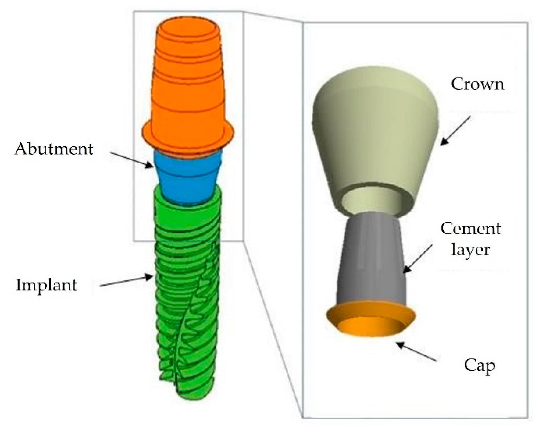
Two distinctive implant macro morphologies, Cyroth and TAC from AoN Implants, Grisignano di Zocco, Italy, were considered and subsequently subjected to three-dimensional (3D) modeling via computer-aided design (CAD) software (Autodesk Inventor 2023, San Francisco, CA, USA), as depicted in Figure 2.
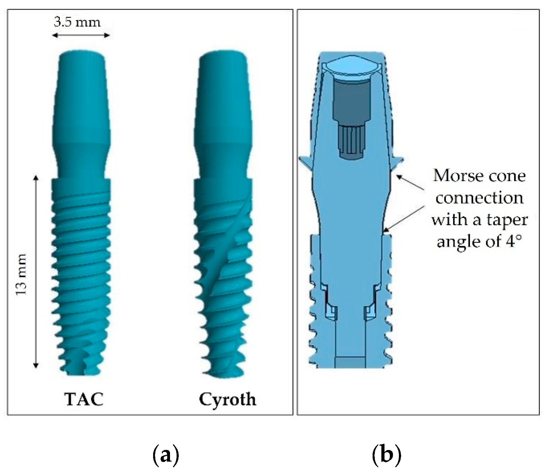
The implants exhibited a diameter of 3.5 mm and a length of 13 mm, featuring a conometric connection between the abutment and coping at a taper angle of 4° and between the fixture and the abutment (Figure 3).
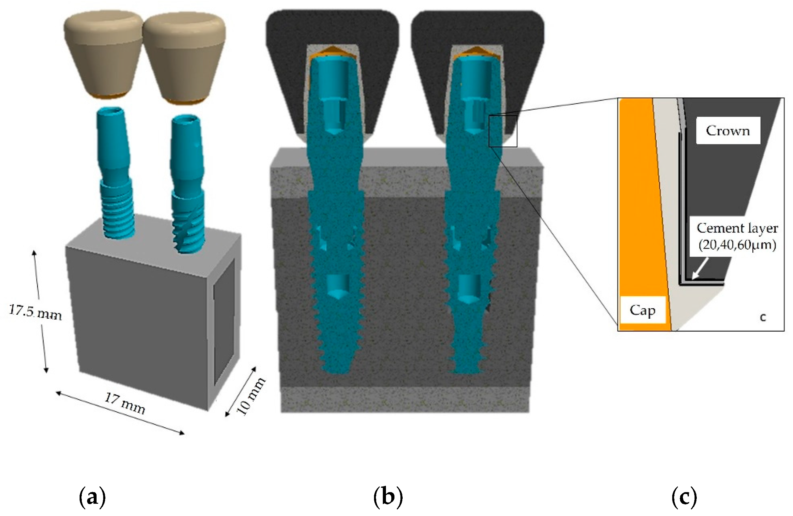
After establishing the geometric characteristics of the implants, it was imperative to model the surrounding bone structure. To achieve this, a mandibular bone block model was created based on cross-sectional images of the right first molar from a computed tomography (CT) scan [40]. The cortical bone area measured 2 mm in thickness. To streamline the analysis and minimize computational time, the bone’s longitudinal dimension was extended to 17 mm to accommodate the insertion of two implants (Figure 4a). Subsequently, the implants were subcrestally inserted to a depth of 1.5 mm (Figure 4b). The modeling process entailed examining the impact of three layers of cement (20, 40, 60 µm), as depicted in Figure 4c.

2.2. Material Properties

This study assumed isotropic and homogeneous behaviors for the materials, where isotropic behavior denotes a material behavior in which the mechanical properties remain constant in all directions [40,41,42,43,44]. Numerous studies have shown that for bone, mechanical properties are density-dependent [45,46,47]. In this context, bone quality was categorized as D1/D2, according to the Misch classification [43]. The coping, abutment, and implant were modeled using a Ti6Al4V titanium alloy, while the crown was modeled in zirconia. The cement utilized was a resin-based auto-polymerizing Multilink Hybrid Abutment (MHA) type (Ivoclar Vivadent, Schaan, Liechtenstein), as indicated in Table 1 [48].
Conversely, Table 2 summarizes the primary mechanical properties intended for application in the FEA simulation. Specifically, Young's modulus (E) delineates the material’s stiffness, while Poisson's ratio (ν) characterizes the elasticity of an elastic solid subjected to loading conditions [40,48,49,50].

2.3. Constraints and Loading Conditions

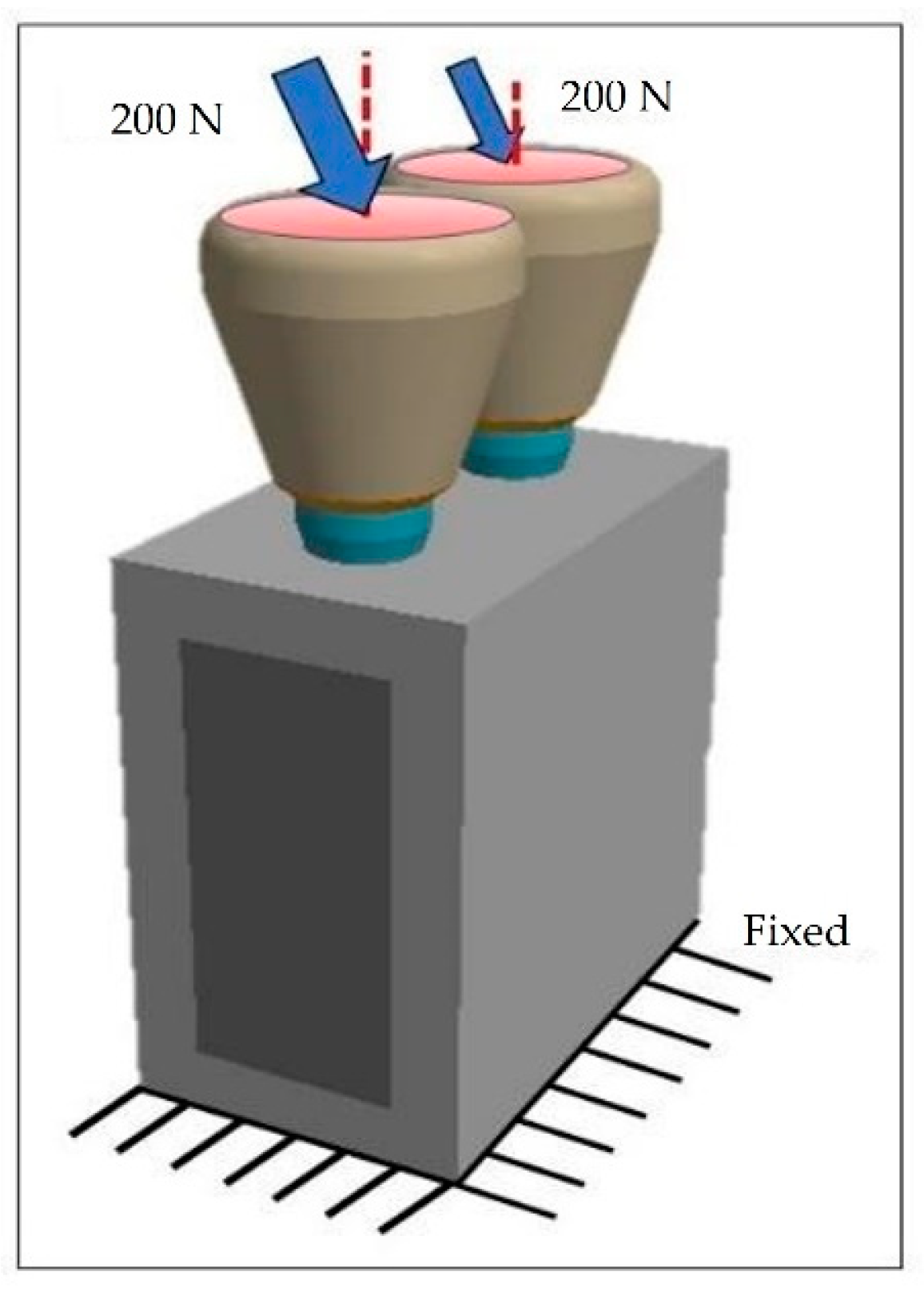
The lower surface of the block, which consists of cortical bone, was restricted from movement in all directions. The loading conditions entailed applying a 45° inclined load relative to the implant’s apical direction, with an intensity of 200 N on the upper surface of the zirconium crown (marked in red), as illustrated in Figure 5 [35].

2.4. Finite Element Analysis (FEA)

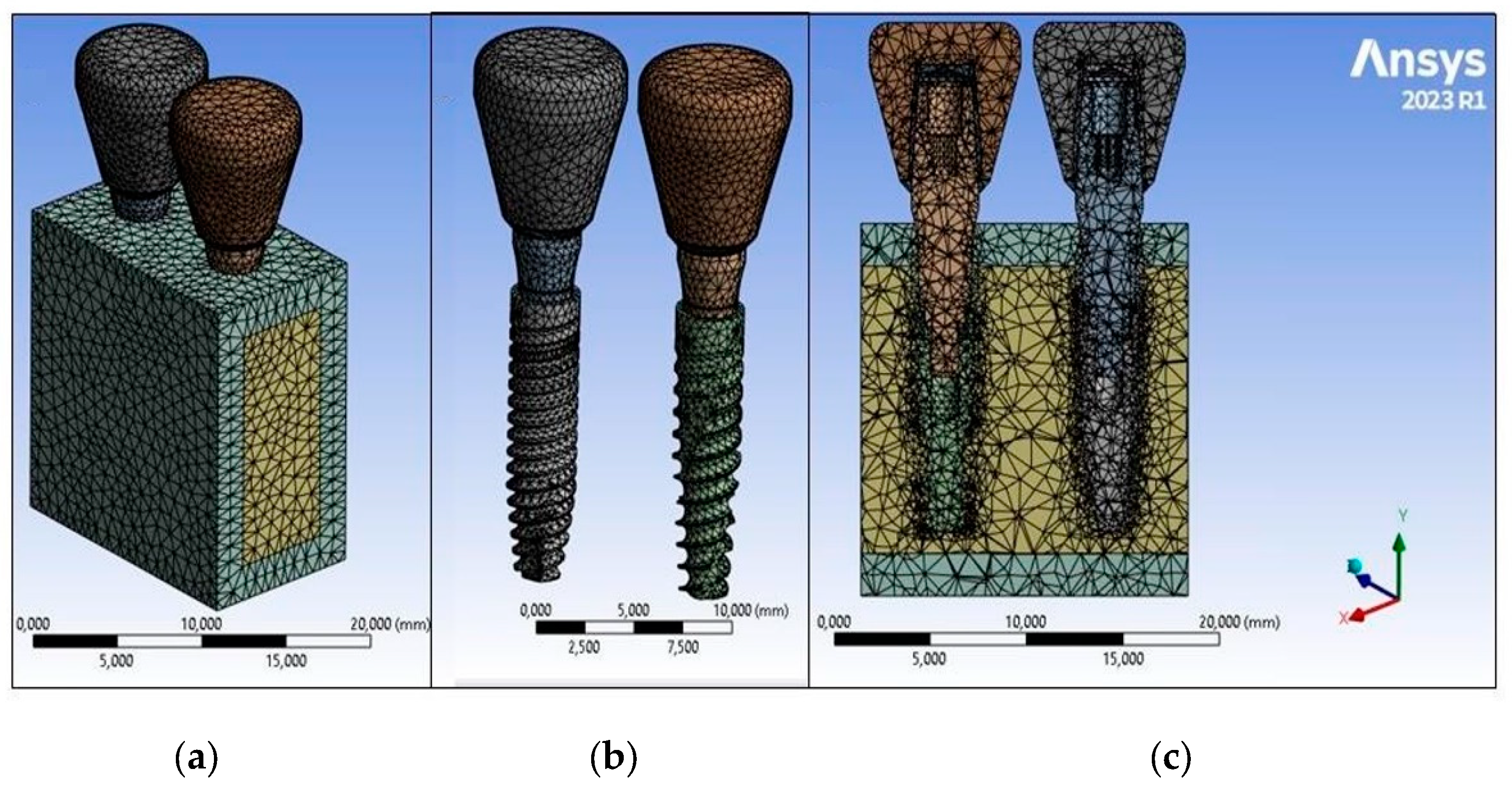
Finite element modeling was executed utilizing FEA software (ANSYS 2023, Workbench, Canonsburg, PA, USA). The implant was extracted from the bone model by employing the volume subtraction operation to generate the implant cavity. Subsequently, the implant was inserted into the bone block, ensuring a precise fit to emulate full osseointegration. All models were discretized into solid elements (Solid 45) with three degrees of freedom in all axes [35]. Following a sensitivity analysis, an optimal element size, balancing computational efficiency and result precision, was determined. A mesh size of 0.5 mm was selected, aligning with established studies in the literature [40,49] (Figure 6).
A static analysis employed a computer equipped with an Intel Core i7 processor running at 2.90 GHz and 16 GB of RAM. After implementing the 3D model in FEA software (ANSYS 2023, Workbench, Canonsburg, PA, USA), von Mises stress values and distributions were evaluated. Stress distribution was visually represented through color maps, with red zones denoting the highest values and blue zones indicating the least critical areas. Subsequently, stress and strain values were assessed at various points within the models and then compared.

3. Results

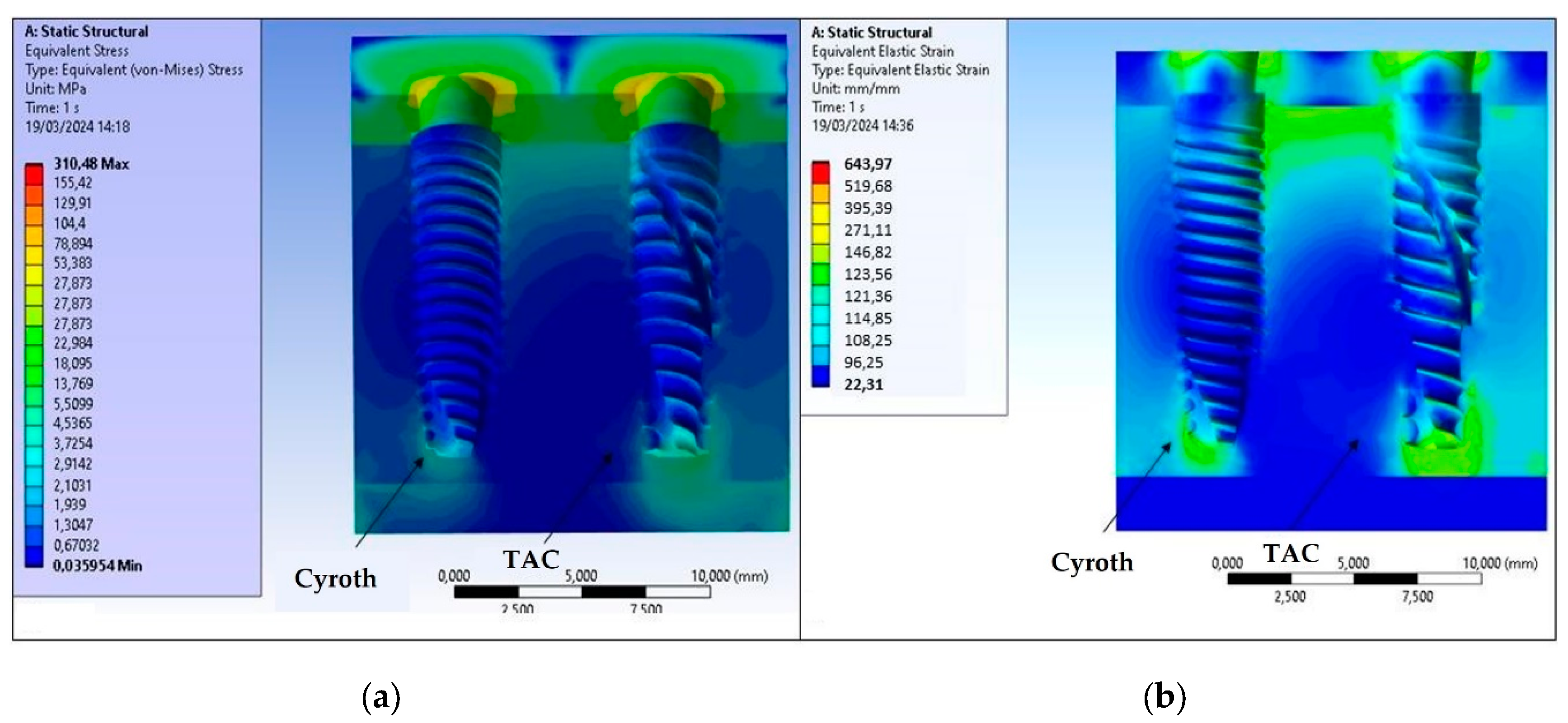
The outcomes derived from computational processing conducted through FEA software (ANSYS 2023, Workbench, Canonsburg, PA, USA) scrutinized von Mises stresses and strains within cortical and trabecular bone tissues. Figure 7 illustrates stress and strain findings in bone using a 20 µm cement layer.
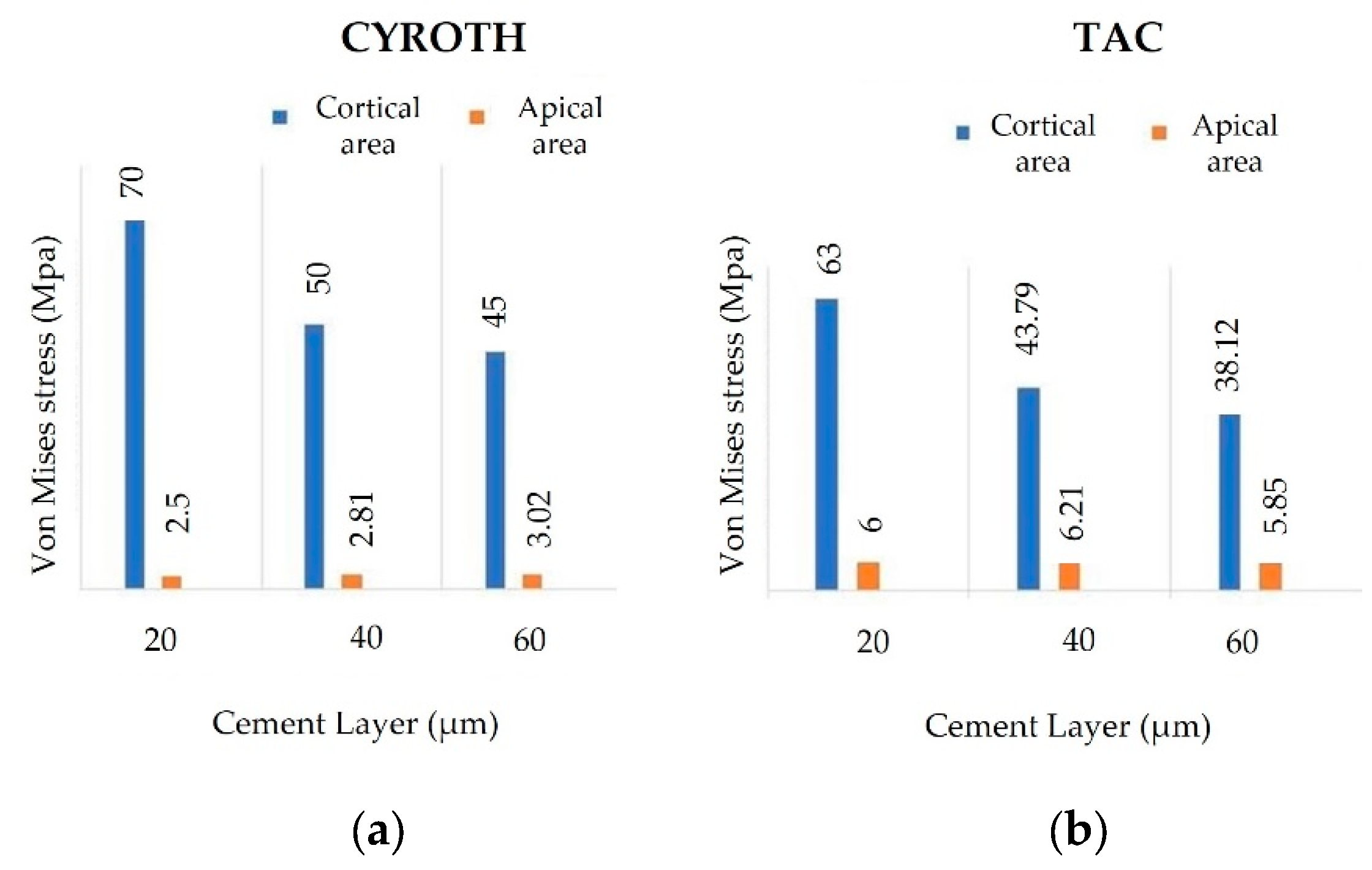
The maximum von Mises stress value manifested in the cortical bone at the implant contact zone. Notably, Figure 7a captured an approximate stress level of 70 MPa for the Cyroth implant, while consistently exhibiting 63 MPa in the same zone for the TAC implant. Moreover, the TAC implant engendered a heightened stress of 6 MPa compared to 2.5 MPa for the Cyroth at the apical zone.
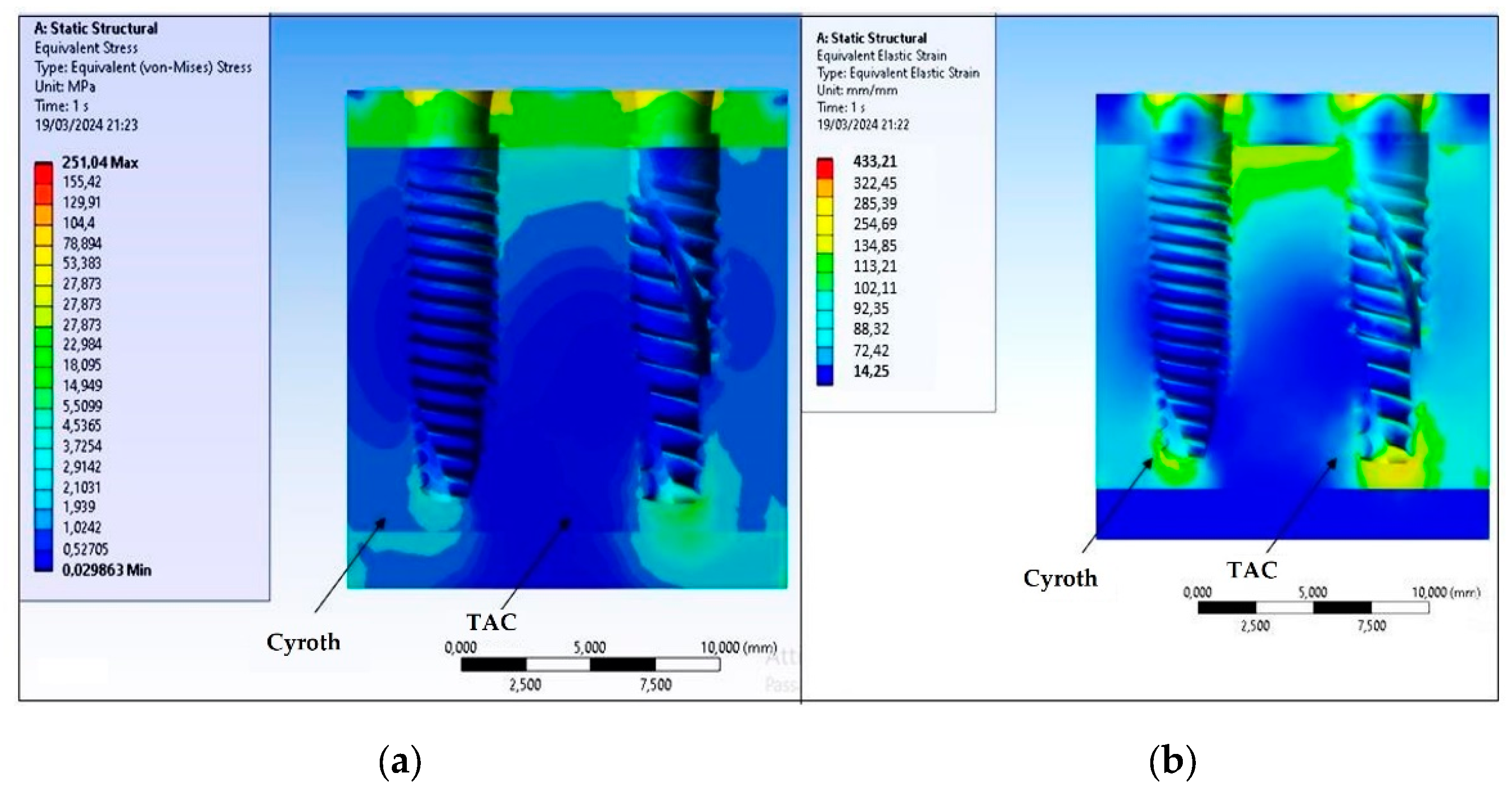
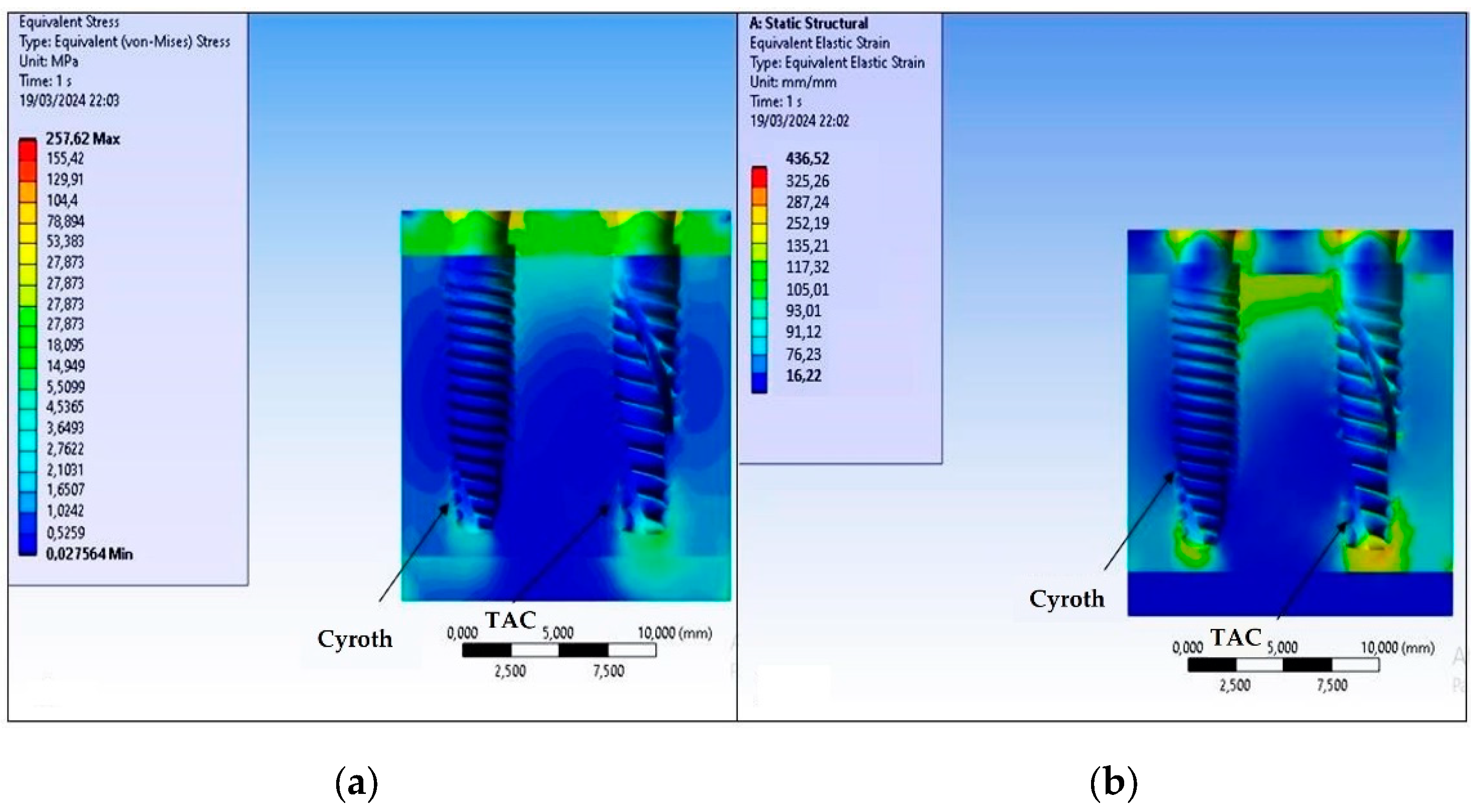
The range of strains on bone differed between the Cyroth and TAC implants in specific zones. In the cortical area, the Cyroth implant produced a greater strain of 643.97 µε compared to the TAC implant’s 532.41 µε. Conversely, in the apical zone, the TAC implant generated a higher strain on the trabecular bone, measuring 256.47 µε compared to the Cyroth implant’s 220.32 µε. Figure 8 depicts the stress and strain results in the bone using a 40 µm cement layer, demonstrating that an increased cement thickness leads to reduced stress and strain for both implants. This reduction is more pronounced when utilizing a 60 µm cement layer, as shown in Figure 9.
The data presented in Figure 10 summarizes the von Mises stress results in the bone with the two implants, considering various cement thicknesses (20, 40, and 60 µm). It was observed that there was a greater reduction of stress in the cortical bone with both implants. The stress distribution in the apical zone and trabecular bone demonstrated a relatively constant trend. Furthermore, it was evident that the TAC implant induced higher stress in the apical area compared to the Cyroth implant across all considered cement thicknesses.
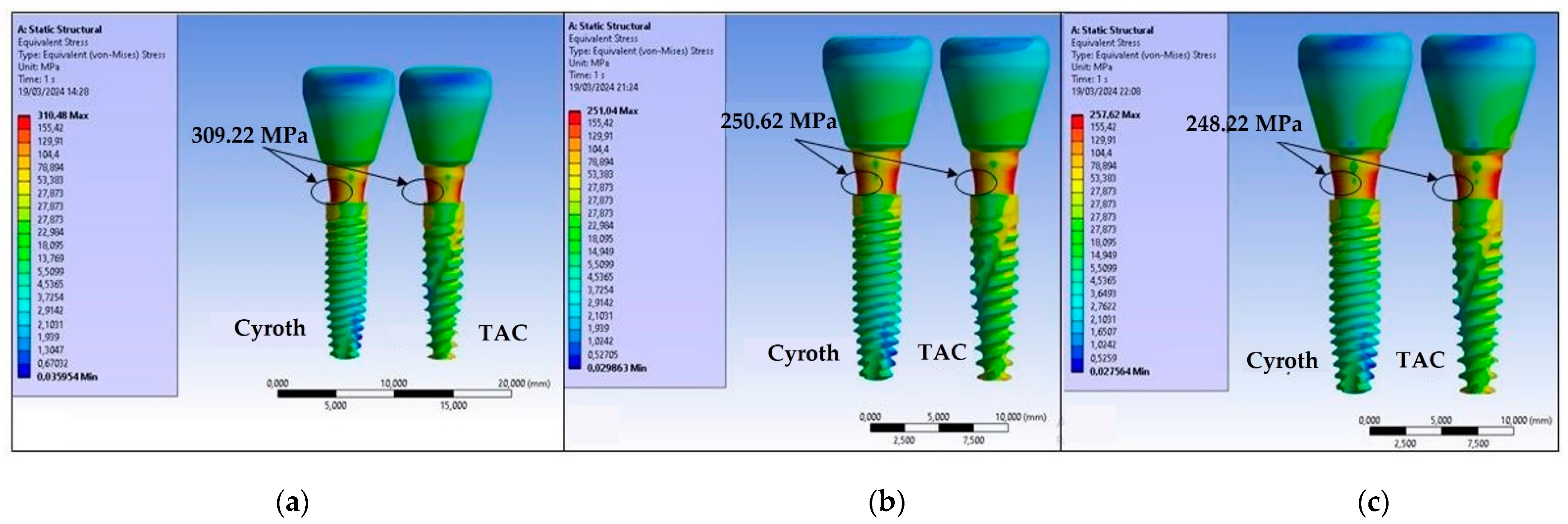
Based on the aforementioned findings, it can be inferred that the range of strains on the bone, considering two different implants and the analysis of various cement thicknesses, fell within the realm of physiological strains [51,52]. Consequently, with regard to bone remodeling, no significant concerns have arisen. It is important to note that the TAC implant registered the lowest strain value when a 60 µm cement layer was used, while the Cyroth implant exhibited the highest strain value when a 20 µm cement layer was employed. Similarly, a reduction in cement thickness with the implants resulted in a decrease in the maximum stress on the abutment neck at the point of contact with the implant (Figure 11).
This identified stress zone is logical as a 200 N load at a 45° angle applied to the prosthetic crown induced bending on the abutment, thereby localizing the stresses. Following the examination of Figure 11b and c, it is evident that the stress reduction became less sensitive for cement thicknesses between 40 and 60 µm. Specifically, with a cement thickness of 20 µm, the maximum stresses at the abutment for both implants were approximately 309.22 MPa. Increasing the thickness to 40 µm reduced the maximum stress to about 250.62 MPa, which stabilized at around 248.22 MPa with a 60 µm cement thickness. While the stresses on the abutments were comparable for both the Cyroth and TAC implants, the stress on the implant body differed. Upon comparing the results in Figure 11 a, b, and c, it is evident that the TAC implant experienced greater stress due to its more tapered morphology, making it less cylindrical than the Cyroth implant. This is evident in the more extensive yellow areas on the TAC implant.
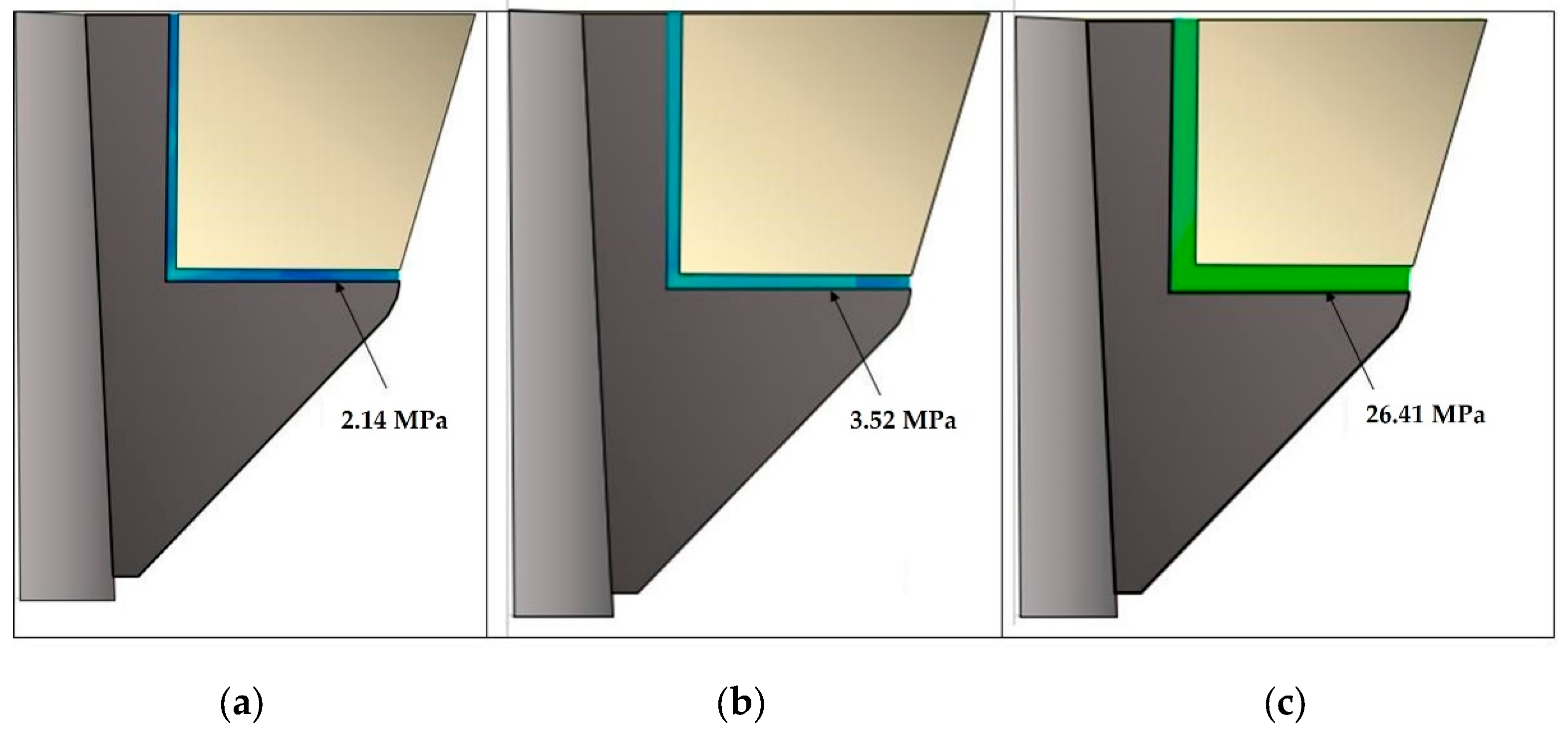
Figure 12 shows the von Mises stress distribution between the cement and the crown and coping prosthetic structures, factoring in the TAC implant, as the stress distribution between the crown, cement, and coping was also equivalent for the Cyroth implant.
As the thickness of the cement increased, there was a corresponding increase in internal stress. This phenomenon elucidated the rationale behind the stiffer system behavior observed when utilizing a thin layer of cement, with the majority of stress being distributed to the implant and bone. Conversely, increasing the thickness resulted in the absorption of stress distribution. Notably, a 60 µm layer exhibited a higher load absorption by the cement at 26.41 MPa, in contrast to the 2.41 MPa load absorption with a reduced thickness of 20 µm. The optimal strength for a resin-based cement is approximately 29.7 MPa and exceeding the 60 µm thickness threshold is implicated in potential strength issues [35].

4. Discussion

The main objective of this study was to evaluate the stress exerted on prosthetic components and bone through FEA of two different types of implants. This involved varying the thickness of resin-based cement (20, 40, and 60 µm) on a zirconia crown restoration using a conometric connection between the coping and the abutment. The findings obtained, consistent with existing literature, indicated that an increase in cement thickness from 20 to 60 µm resulted in reduced stresses, especially on cortical bone. Additionally, it was observed that this increase in thickness induced an alteration in the internal stress distribution within the cement, leading to critical mechanical strength phenomena for thicknesses of 60 µm. This stress level approached the strength of resin cement. Consequently, the null hypothesis is rejected due to the significant impact on stress transmission within prosthetic structures and peri-implant tissues as a result of changes in cement thickness.
The selection between cemented and screw-retained prostheses in implant dentistry is a subject of considerable interest among dental professionals [13,14,15,53]. Cemented prostheses present several advantages, encompassing precise fitting, robust biomechanical stability, absence of screw access holes, superior occlusal design, and adaptability to accommodate malpositioned implant prosthetics. Additionally, the cement layer serves as a shock absorber, compensating for dimensional variations between the restoration and the anchor element. However, a potential drawback of cemented prostheses is the challenge associated with the removal of excess cement, which can result in complications such as periimplantitis, peri-implant mucositis, and marginal bone loss [8,9,10,54]. Conversely, screw-retained prostheses offer facilitated retrieval. Despite their benefits, they are more susceptible to technical issues, including component fractures and screw loosening [12,55,56]. Moreover, in a cemented restoration, the reduction in the number of screws restricts the micro-movement of the components. While this reduction may be advantageous in addressing issues linked to the mechanical strength of prosthetic components, it also influences the transmission of forces within the implant system. Indeed, as previously demonstrated, the decrease in micromovements and, thus, the capacity to absorb forces, results in an altered stress distribution, particularly on bone structures [57]. Direct transmission of masticatory loads from the occlusal surface to the bone is evident, signifying that forces generated during mastication may not be adequately dissipated by prosthetic components, ultimately leading to heightened stress on bone tissues [57,58].
Addressing the aforementioned challenges associated with the two existing retention systems, both dental research and industry have introduced a novel prosthetic connection known as Morse cone (conometrics) [59]. This innovative connection involves the utilization of a conometric coping, which serves as an intermediary component between the implant abutment and the prosthetic crown. The conometric connection features a male cone on the connecting element (abutment) and a female cone on the prefabricated cap, meticulously designed to interlock securely without the requirement of cement or screws [60]. This approach facilitated the secure attachment of prosthetic components, mitigating the risk of cement residue or screw loosening, while also allowing for convenient removal and reinsertion of the prosthesis when necessary. Furthermore, the tapered connection not only ensures stability but also promotes enhanced hygiene by eliminating potential cement-related inflammation and peri-implant complications.
The prosthetic crown, as previously mentioned, is affixed to the tapered coping using cement. Cements used in dental applications are pivotal to the success of restorations. In the context of tapered coping connections, the primary role of the cement is to securely bond the prosthetic crown to the coping while ensuring superior aesthetic properties. The mechanical attributes of the cement, including type, thickness, and stiffness, are fundamental not only for ensuring adequate retention but also for facilitating load transmission without creating regions of stress concentration that may lead to excessive bone resorption. Resin cement has garnered increasing favor within the dental field owing to its elevated compressive and tensile strength, low solubility, and favorable aesthetic properties. These cements are distinguished by their capacity to withstand substantial force and stress. Moreover, in vitro and clinical studies have indicated that resin-composite adhesion can contribute toward stress distribution and prevention of crack propagation within ceramic material repairs [35,50,61].
As regards the choice of cement thickness, in an FEA study by El-Anwar et al. [35], it was observed that increasing the thickness of the cement layer from 40 to 60 µm resulted in a decrease in the maximum von Mises stress on the cortical bone, while its impact on the trabecular bone was found to be negligible. Furthermore, it was noted that increasing the cement thickness led to a reduction in the maximum von Mises stress for both glass ionomer and zinc phosphate resin cement, with varying percentage changes based on the thickness and type of the cement. Generally, increasing the cement thickness may promote a more favorable stress distribution, thereby minimizing the maximum stress on cortical bones and exerting a relatively lesser influence on trabecular bones. Nonetheless, the use of excessively thick layers could potentially lead to "washout", a phenomenon characterized by the removal of cement due to external stresses, such as those induced by oral fluids. Notably, thicknesses exceeding 75 µm were found to expedite washout and result in retention failure. Consequently, this study sought to examine, via the FEA method, the mechanical behavior of the resin-based cement utilized to affix prosthetic crowns on a tapered coping positioned on the abutments of two distinct implants, Cyroth and TAC, each characterized by unique implant shapes.
The models utilized in this study may not fully comprehensively replicate actual human oral conditions, warranting further clinical studies to authenticate the findings. This methodology also presents drawbacks related to software familiarity, the impact of configuration parameters on results, and the requirement for comprehensive knowledge about the behavior of analyzed components. It is important to note that while FEA is a valuable numerical investigation method, it cannot fully simulate tissue behavior or accurately represent the complexity of the biological field. Moreover, it is susceptible to potential numerical errors. The assumption of homogeneity, isotropy, and linear elasticity of all materials, and the condition of complete osseointegration between the bone and implants were posited, despite the impracticality of these assumptions in clinical practice [62].
Notwithstanding the limitations of the presented FEA study, a notable conclusion could be drawn. Indeed, the preliminary results suggested that increasing cement thickness can reduce stress, particularly in cortical bone, compared to trabecular bone, which has a more uniform stress distribution at the interface with the implant body. The Cyroth implant was observed to induce a greater stress field and strain on the cortical bone than the TAC implant, while the TAC implant generated more stress and strain in the apical zone. It was noted that as cement thickness increases, the internal stress absorbed by the cement also increases. In addition, criticalities may arise when the cement thickness reaches approximately 60 µm as the absorbed stress value approaches the material’s strength value. Both implants, when loaded at the occlusal surface of the zirconia prosthesis with a 200 N load inclined at 45° to the apical direction, exhibited a strain field within the range of physiological bone behavior as proposed by Frost [63].
Further investigational studies involving variations in prosthetic crown material or bone quality are necessary to comprehend the optimal trade-off between cement type and thickness.

Author Contributions

Conceptualization, B.T., M.C. and L.C.; methodology, M.C., T.R., L.C. and A.C.; software, M.C.; validation, B.T., A.P. and N.D.P.; formal analysis, M.C. and T.R.; investigation, M.C., T.R., G.D., A.M.I., F.I. and A.C.; resources, B.T.; data curation, N.D.P. and T.R.; writing—original draft preparation, M.C., T.R. and B.T.; writing—review and editing, N.D.P. and T.R.; visualization, A.P.; supervision, B.T. and N.D.P.; project administration, A.P. and B.T. All authors have read and agreed to the published version of the manuscript

Funding

This research received no external funding.

Data Availability Statement

All experimental data to support the findings of this study are available from the corresponding author upon request.

Acknowledgements

The authors gratefully thank AoN Implants Company, Grisignano di Zocco, Italy, for all the mathematical data on the implants.

Conflicts of Interest

The authors declare no conflicts of interest.

References

  1. Zarone, F.; Russo, S.; Sorrentino, R. From porcelain-fused-to-metal to zirconia: clinical and experimental considerations. Dent. Mater. 2011, 27, 83–96. [Google Scholar] [CrossRef] [PubMed]
  2. Alsarani, M.; Souza, G.; Rizkalla, A.; El-Mowafy, O. Influence of crown design and material on chipping resistance of all-ceramic molar crowns: An in vitro study. Dent. Med. Probl. 2018, 55, 35–42. [Google Scholar] [CrossRef] [PubMed]
  3. Poggio, C.E.; Ercoli, C.; Rispoli, L.; Maiorana, C.; Esposito, M. Metal-free materials for fixed prosthodontic restorations. Cochrane Database Syst. Rev. 2017, 12, CD009606. [Google Scholar] [CrossRef] [PubMed]
  4. Anusavice, K.J. Standardizing failure, success, and survival decisions in clinical studies of ceramic and metal-ceramic fixed dental prostheses. Dent. Mater. 2012, 28, 102–111. [Google Scholar] [CrossRef] [PubMed]
  5. Sadowsky, S.J. Has zirconia made a material difference in implant prosthodontics? A review. Dent. Mater. 2020, 36, 1–8. [Google Scholar] [CrossRef] [PubMed]
  6. Sorrentino, R.; Triulzio, C.; Tricarico, M.G.; Bonadeo, G.; Gherlone, E.F.; Ferrari, M. In vitro analysis of the fracture resistance of CAD-CAM monolithic zirconia molar crowns with different occlusal thickness. J. Mech. Behav. Biomed. Mater. 2016, 61, 328–333. [Google Scholar] [CrossRef]
  7. Patzelt, S.B.; Spies, B.C.; Kohal, R.J. CAD/CAM-fabricated implant-supported restorations: A systematic review. Clin. Oral Implant. Res. 2015, 26, 77–85. [Google Scholar] [CrossRef]
  8. Wasiluk, G.; Chomik, E.; Gehrke, P.; Pietruska, M.; Skurska, A.; Pietruski, J. Incidence of undetected cement on CAD/CAM monolithic zirconia crowns and customized CAD/CAM implant abutments. A prospective case series. Clin. Oral Implant. Res. 2017, 28, 774–778. [Google Scholar] [CrossRef]
  9. Wittneben, J.G.; Millen, C.; Bragger, U. Clinical performance of screw-versus cement-retained fixed implantsupported reconstructions—A systematic review. Int. J. Oral Maxillofac. Implant. 2014, 29, 84–98. [Google Scholar] [CrossRef]
  10. Hamed, M.T.; Abdullah, M.H.; Khalid, A.S.; Hossam, H.A.B.; Hussein, N.G. A Systematic Review of Screw versus Cement- Retained Fixed Implant Supported Reconstructions. Clin. Cosmet. Investig. Dent. 2020, 12, 9–16. [Google Scholar] [CrossRef]
  11. Shadid, R.; Sadaqa, N. A comparison between screw- and cement-retained implant prostheses. A literature review. J. Oral Implant. 2012, 38, 298–307. [Google Scholar] [CrossRef] [PubMed]
  12. Sailer, I.; Mühlemann, S.; Zwahlen, M.; Hämmerle, C.H.; Schneider, D. Cemented and screw-retained implant reconstructions: A systematic review of the survival and complication rates. Clin. Oral Implant. Res. 2012, 23, 163–201. [Google Scholar] [CrossRef] [PubMed]
  13. Nissan, J.; Narobai, D.; Gross, O.; Ghelfan, O.; Chaushu, G. Long-term outcome of cemented versus screwretained implant supported partial restorations. Int. J. Oral Maxillofac Implant. 2011, 26, 1102–1107. [Google Scholar] [PubMed]
  14. Kraus, R.D.; Epprecht, A.; Hämmerle, C.H.F.; Sailer, I.; Thoma, D.S. Cemented vs screw retained zirconiabased single implant reconstructions: A 3-year prospective randomized controlled clinical trial. Clin. Implant. Dent. Relat. Res. 2019, 21, 578–585. [Google Scholar] [CrossRef] [PubMed]
  15. Wittneben, J.G.; Joda, T.; Weber, H.P.; Brägger, U. Screw retained vs. cement retained implant-supported fixed dental prosthesis. Periodontol 2000 2017, 73, 141–151. [Google Scholar] [CrossRef] [PubMed]
  16. Zarone, F.; Sorrentino, R.; Traini, T.; Di lorio, D.; Caputi, S. Fracture resistance of implant-supported screw- versus cement-retained porcelain fused to metal single crowns: SEM fractographic analysis. Dent. Mater. 2007, 23, 296–301. [Google Scholar] [CrossRef] [PubMed]
  17. Ceddia, M.; Romasco, T.; Comuzzi, L.; Specchiulli, A.; Piattelli, A.; Lamberti, L.; Di Pietro, N.; Trentadue, B. Finite-Element Analysis Study Comparing Titanium and Polyetheretherketone Caps in a Conometric Connection between Implant and Prosthesis. Adv. Eng. Mater. 2024, 2400198. [Google Scholar] [CrossRef]
  18. Albiero, A.M.; Benato, R.; Momic, S.; Degidi, M. Guided-Welded Approach Planning Using a Computer-Aided Designed Prosthetic Shell for Immediately Loaded Complete-Arch Rehabilitations Supported by Conometric Abutments. J. Prosthet. Dent. 2019, 122, 510–515. [Google Scholar] [CrossRef] [PubMed]
  19. Antonaya-Martin, J.; Rio-Highsmith, J.D.; Moreno-Hay, I.; Lillo-Rodríguez, J.; Gomez-Polo, M.; CeleminViñuela, A. CAD/CAM Conic Crowns for Predictable Retention in Implant-Supported Prostheses. Int. J. Prosthodont. 2016, 29, 230–232. [Google Scholar] [CrossRef]
  20. Albiero, A. M.; Benato, R.; Momic, S.; Degidi, M. Computer-Aided Crown Design Using Digital Scanning Technology for Immediate Postextraction Single-Implant Restorations Supported by Conical Indexed Abutments. Int. J. Periodont. Rest. Dent. 2021, 41, 135–140. [Google Scholar] [CrossRef]
  21. Gundogdu, M.; Aladag, L.I. Effect of adhesive resin cements on bond strength of ceramic core materials to dentin. Niger. J. Clin. Pract. 2018, 213, 367–374. [Google Scholar] [CrossRef] [PubMed]
  22. Johnson, G.H.; Lepe, X.; Patterson, A.; Schäfer, O. Simplified cementation of lithium disilicate crowns: Retention with various adhesive resin cement combinations. J. Prosthet. Dent. 2018, 1195, 826–832. [Google Scholar] [CrossRef] [PubMed]
  23. Dressano, D.; Salvador, M.V.; Oliveira, M.T.; Marchi, G.M.; Fronza, B.M.; Hadis, M.; Palin, W.M.; Lima, A.F. Chemistry of novel and contemporary resin-based dental adhesives. J. Mech. Behav. Biomed. Mater. 2020, 110, 103875. [Google Scholar] [CrossRef] [PubMed]
  24. Carville, R.; Quinn, F. The selection of adhesive systems for resin-based luting agents. J. Ir. Dent. Assoc. 2008, 54, 218–222. [Google Scholar] [PubMed]
  25. Wilson, A.D. Glass-ionomer cement origins, development and future. Clin. Mater. 1991, 7, 275–282. [Google Scholar] [CrossRef] [PubMed]
  26. Ansari, S.; Moshaverinia, M.; Roohpour, N.; Chee, W.W.L.; Schricker, S.R.; Moshaverinia, A. Properties of a proline-containing glass ionomer dental cement. J. Prosthet. Dent. 2013, 110, 408–413. [Google Scholar] [CrossRef] [PubMed]
  27. Bahsi, E.; Sagmak, S.; Dayi, B.; Cellik, O.; Akkus, Z. The evaluation of microleakage and fluoride release of different types of glass ionomer cements. Niger. J. Clin. Pract. 2019, 22, 961. [Google Scholar] [CrossRef] [PubMed]
  28. Berg, J.H.; Croll, T.P. Glass ionomer restorative cement systems: An update. Pediatr. Dent. 2015, 37, 116–124. [Google Scholar] [PubMed]
  29. Powers, J.M. Self-adhesive Resin Cements: Characteristics, Properties, and Manipulation. AEGIS Dental Network. Funct. Esthet. Restor. Dent. 2008, 2, 34–40. [Google Scholar]
  30. Weiser, F.; Behr, M. Self-Adhesive Resin Cements: A Clinical Review. J. Prosthodont. 2015, 24, 100–108. [Google Scholar] [CrossRef]
  31. Makkar, S.; Malhotra, N. Self-adhesive resin cements: A new perspective in luting technology. Dent. Update 2013, 40, 758–768. [Google Scholar] [CrossRef] [PubMed]
  32. Marghalani, H.Y. Sorption and solubility characteristics of self-adhesive resin cements. Dent. Mater. 2012, 28, e187–e198. [Google Scholar] [CrossRef] [PubMed]
  33. Sidhu, S.K. Glass-ionomer cement restorative materials: A sticky subject? Aust. Dent. J. 2011, 56 (Suppl. S1), 23–30. [Google Scholar] [CrossRef] [PubMed]
  34. Walia, T.; Brigi, C.; Ziadkhani, M.M.; Khayat, A.A.; Tabibzadeh, Z. Retention Force of Glass Ionomer Based Luting Cements with Posterior Primary Zirconium Crowns—A Comparative in Vitro Study. J. Clin. Pediatr. Dent. 2021, 45, 259–264. [Google Scholar] [CrossRef] [PubMed]
  35. El-Anwar, M.; Tamam, R.A.; Fawzy, U.M.; Yousief, S.A. The effect of luting cement type and thickness on stress distribution in upper premolar implant restored with metal ceramic crowns. Tanta Dental Journal. 2015, 77. [Google Scholar] [CrossRef]
  36. Shillingburg, H.T.; Sather, D.A. Fundamentals of fixed prosthodontics, 4th ed.; Quintessence Pub: Chicago, 2012. [Google Scholar]
  37. Anusavice, K.J.; Hojjatie, B. Stress distribution in metal-ceramic crowns with a facial porcelain margin. J. Dent. Res. 1987, 66, 1493–1498. [Google Scholar] [CrossRef]
  38. Chai, J.Y.; Steege, J.W. Effects of labial margin design on stress distribution of a porcelain-fused-to-metal crown. J. Prosthodont. 1992, 1, 18–23. [Google Scholar] [CrossRef] [PubMed]
  39. Di Pietro, N.; Ceddia, M.; Romasco, T.; De Bortoli, J.N.; Mello, B.F.; Tumedei, M.; Specchiulli, A.; Piattelli, A.; Trentadue, B. Appl. Sci. 2023, 13, 8147. [CrossRef]
  40. Morgan, E.F.; Unnikrisnan, G.U.; Hussein, A.I. Bone Mechanical Properties in Healthy and Diseased States. Annu. Rev. Biomed. Eng. 2018, 20, 119–143. [Google Scholar] [CrossRef] [PubMed]
  41. Peng, L.; Bai, J.; Zeng, X.; Zhou, Y. Comparison of isotropic and orthotropic material property assignments on femoral finite element models under two loading conditions. Med. Eng. Phys. 2006, 28, 227–233. [Google Scholar] [CrossRef]
  42. Misch, C.E.; Qu, Z.; Bidez, M.W. Mechanical properties of trabecular bone in the human mandible: implications for dental implant treatment planning and surgical placement. J. Oral Maxillofac. Surg. 1999, 57, 700–706. [Google Scholar] [CrossRef] [PubMed]
  43. Li, J.; Jansen, J.A.; Walboomers, X.F.; van den Beucken, J.J. Mechanical aspects of dental implants and osseointegration: A narrative review. J. Mech. Behav. Biomed. Mater. 2020, 103, 103574. [Google Scholar] [CrossRef] [PubMed]
  44. Ferretti, J.L.; Capozza, R.F.; Mondelo, N.; Zanchetta, J.R. Interrelationships between densitometric, geometric, and mechanical properties of rat femora: inferences concerning mechanical regulation of bone modeling. J. Bone Miner. Res. 2020, 8, 1389–1396. [Google Scholar] [CrossRef]
  45. Ramos, A.; Nyashin, Y.; Mesnard, M. Influences of geometrical and mechanical properties of bone tissues in mandible behaviour–experimental and numerical predictions. Comput. Methods Biomech. Biomed. Engin. 2017, 20, 1004–1014. [Google Scholar] [CrossRef]
  46. Azcarate-Velázquez, F.; Castillo-Oyagüe, R.; Oliveros-López, L.G.; Torres-Lagares, D.; Martínez-González, Á.J.; Pérez-Velasco, A.; Lynch, C.D.; Gutiérrez-Pérez, J.L.; Serrera-Figallo, M.Á. Influence of bone quality on the mechanical interaction between implant and bone: A finite element analysis. J Dent. 2019, 88, 103161. [Google Scholar] [CrossRef]
  47. Oddbratt, E.; Hua, L.; Chrcanovic, B.R.; Papia, E. Bond strength of zirconia- or polymer-based copings cemented on implant-supported titanium bases - an in vitro study. Biomater. Investig. Dent. 2021, 8, 129–136. [Google Scholar] [CrossRef]
  48. Ceddia, M.; Lamberti, L.; Trentadue, B. FEA Comparison of the Mechanical Behavior of Three Dental Crown Materials: Enamel, Ceramic, and Zirconia. Materials (Basel). 2024, 17, 673. [Google Scholar] [CrossRef]
  49. Nakamura, T.; Wakabayashi, K.; Kinuta, S.; Nishida, H.; Miyamae, M.; Yatani, H. Mechanical properties of new self-adhesive resin-based cement. J. Prosthodont. Res. 2010, 54, 59–64. [Google Scholar] [CrossRef] [PubMed]
  50. Ouldyerou, A.; Merdji, A.; Aminallah, L.; Roy, S.; Mehboob, H.; Özcan, M. Biomechanical performance of Ti-PEEK dental implants in bone: An in-silico analysis. J. Mech. Behav. Biomed. Mater. 2022, 134, 105422. [Google Scholar] [CrossRef]
  51. Jafariandehkordi, A.; Jafariandehkordi, Z. A finite element optimization of the design variables of a dental implant screw based on the Mechanostat Theory. Computer Methods and Programs in Biomedicine Update 2021, 1, 100033. [Google Scholar] [CrossRef]
  52. Lee, A.; Okayasu, K.; Wang, H.L. Screw- versus cement-retained implant restorations: Current concepts. Implant. Dent. 2010, 19, 8–15. [Google Scholar] [CrossRef] [PubMed]
  53. Gapski, R.; Neugeboren, N.; Pomeranz, A.Z.; Reissner, M.W. Endosseous implant failure influenced by crown cementation: A clinical case report. Int. J. Oral Maxillofac. Implant. 2008, 23, 943–946. [Google Scholar] [PubMed]
  54. Chee, W.; Jivraj, S. Screw versus cemented implant-supported restorations. Br. Dent. J. 2006, 201, 501–507. [Google Scholar] [CrossRef] [PubMed]
  55. Michalakis, K.X.; Hirayama, H.; Garefis, P.D. Cement-retained versus screw-retained implant restorations: A critical review. Int. J. Oral Maxillofac. Implant. 2003, 18, 719–728. [Google Scholar] [PubMed]
  56. Lee, J.-H.; Jang, H.Y.; Lee, S.Y. Finite Element Analysis of Dental Implants with Zirconia Crown Restorations: Conventional Cement-Retained vs. Cementless Screw-Retained. Materials 2021, 14, 2666. [Google Scholar] [CrossRef] [PubMed]
  57. Rangert, B.; Gunne, J.; Glantz, P.O.; Svensson, A. Vertical load distribution on a three-unit prosthesis supported by a natural tooth and a single Brånemark implant. An in vivo study. Clin. Oral Implant. Res. 1995, 6, 40–46. [Google Scholar] [CrossRef] [PubMed]
  58. Degidi, M.; Nardi, D.; Sighinolfi, G.; Degidi, D. The conometric concept for the definitive rehabilitation of a single posterior implant by using a conical indexed abutment: A technique. J. Prosthet. Dent. 2020, 123, 576–579. [Google Scholar] [CrossRef] [PubMed]
  59. Lupi, S.M.; Todaro, C.; De Martis, D.; Blasi, P.; Rodriguez y Baena, R.; Storelli, S. The Conometric Connection for the Implant-Supported Fixed Prosthesis: A Narrative Review. Prosthesis 2022, 4, 458–467. [Google Scholar] [CrossRef]
  60. Elbieh, A.; Othman, H.; Haggag, K. Effect of Cement Gap on the Retention of Zirconia Crowns. Al-Azhar J. Dent. Sci. 2020, 23, 235–240. [Google Scholar] [CrossRef]
  61. Chen, X.; Mao, B.; Zhu, Z.; Yu, J.; Lu, Y.; Zhang, Q.; Yue, L.; Yu, H. A three-dimensional finite element analysis of mechanical function for 4 removable partial denture designs with 3 framework materials: CoCr, Ti-6Al-4V alloy and PEEK. Sci. Rep. 2019, 9. [Google Scholar] [CrossRef]
  62. Frost, H.M. Perspectives: bone’s mechanical usage windows. Bone Miner. 1992, 19, 257–271. [Google Scholar] [CrossRef] [PubMed]
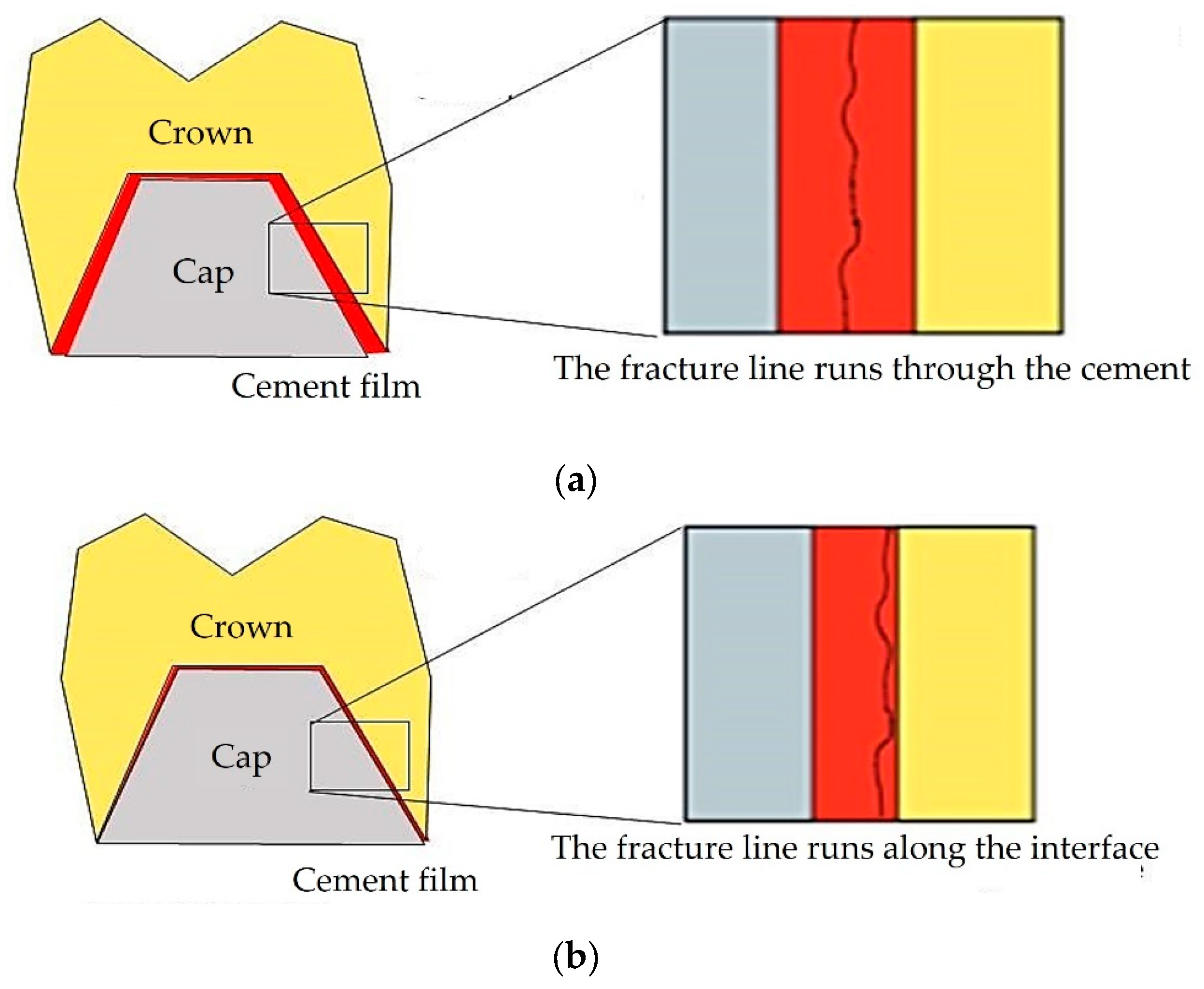
Figure 1. Failure patterns for (a) thin and (b) thick cement films beneath crowns.
Preprints 108966 g001
Figure 2. Representative three-dimensional (3D) model of the analyzed components.
Preprints 108966 g002
Figure 3. 3D models of the implants: a) TAC and Cyroth (AoN Implants, Grisignano di Zocco, Italy) implants; b) cross-sectional view of the implant-abutment and abutment-cap conometric connections.
Preprints 108966 g003
Figure 4. Complete 3D model: a) bone block dimensions; b) cross-sectional representation of the subcrestal implant insertion (1.5 mm); c) cross-sectional detail of the interface between the coping and crown, encompassing varying cement thicknesses (20, 40, 60 μm).
Preprints 108966 g004
Figure 5. Loading and constraints conditions.
Preprints 108966 g005
Figure 6. Model meshes: (a) mesh of the entire model; (b) mesh of the two implants; (c) mesh of the sectional view of the model.
Preprints 108966 g006
Figure 7. FEA results on bone testing a cement layer of 20 µm: (a) von Mises stress; (b) equivalent elastic strain. .
Preprints 108966 g007
Figure 8. FEA results on bone testing a cement layer of 40 µm: (a) von Mises stress; (b) equivalent elastic strain.
Preprints 108966 g008
Figure 9. FEA results on bone testing a cement layer of 60 µm: (a) von Mises stress; (b) equivalent elastic strain.
Preprints 108966 g009
Figure 10. Von Mises stress results for (a) Cyroth and (b) TAC implants, considering various cement layers (20, 40, and 60 µm).
Preprints 108966 g010
Figure 11. Von Mises stress values on prosthetic components with various cement thicknesses: a) 20 µm, b) 40 µm, and c) 60 µm.
Preprints 108966 g011
Figure 12. Maximum von Mises stress values on cement based on its thickness: a) 20 µm, b) 40 µm, and c) 60 µm.
Preprints 108966 g012
Table 1. Type and chemical composition of cement used in the analysis.
Cement Type / Curing Composition
Multilink Hybrid Abutment
(MHA)
Resin-based cement/ Auto-polymerization Dimethacrylate, HEMA1, fillers (barium glass, ytterbium (III) fluoride, spheroid mixed oxides, titanium dioxide), MMA2, PMMA3, dimethacrylates, initiators
1 Hydroxyethyl methacrylate, 2 Methyl methacrylate, 3 polymethyl methacrylate.
Table 2. List of material properties used in the finite element analysis (FEA).
Model Material Young’s Modulus (GPa) Poisson’s ratio (ν)
Crown Zirconia 205 0.34
Cement Resin-based cement (MHA) 6.3 0.25
Cap Ti6Al4V 110 0.35
Abutment Ti6Al4V 110 0.35
Implant Ti6Al4V 110 0.35
Jaw bone 1 Spongy 1.37 0.30
Jaw bone 2 Cortical 13.7 0.30
Disclaimer/Publisher’s Note: The statements, opinions and data contained in all publications are solely those of the individual author(s) and contributor(s) and not of MDPI and/or the editor(s). MDPI and/or the editor(s) disclaim responsibility for any injury to people or property resulting from any ideas, methods, instructions or products referred to in the content.
Copyright: This open access article is published under a Creative Commons CC BY 4.0 license, which permit the free download, distribution, and reuse, provided that the author and preprint are cited in any reuse.
Prerpints.org logo

Preprints.org is a free preprint server supported by MDPI in Basel, Switzerland.

Subscribe

© 2024 MDPI (Basel, Switzerland) unless otherwise stated