Preprint
Article

Entropy Generation Analysis for Combustible Third Grade Fluid Flow through a Slant Channel

Altmetrics

Downloads

69

Views

22

Comments

0

A peer-reviewed article of this preprint also exists.

Submitted:

11 June 2024

Posted:

12 June 2024

You are already at the latest version

Alerts
Abstract
This paper addresses the mixed convective flow and heat transfer in combustible third grade fluid through a slant channel that is filled with a permeable materials. The fluid layer in contact with the lower plate is exposed to convective heating with the ambient while at the upper plate, a constant heat flux is experienced. We employ the spectral quasilinearisation method (SQLM) to the coupled nonlinear flow governing equations. Fluid velocity and temperature profiles, local entropy generation and irreversibility ratio are computed and analysed quantitatively and qualitatively. A residual error analysis demonstrated high accuracy and convergence of the numerical method. The results on flow and thermal effects, entropy generation rate and Bejan number revealed fascinating manifestations that have profound implications in design of thermo-mechanical systems. In particular, the results of the thermal analysis are pertinent to optimal designs of systems that achieve efficient energy utilization.
Keywords: 
Subject: Computer Science and Mathematics  -   Applied Mathematics

1. Introduction

A good number of researchers have paid renewed interest and attention to the flow of reactive fluids because due to technological advancements. In particular, energy transfer and variable viscosity property of a fluid have been of vast interest among researchers [1,2,3,4,5,6,7,8]. Industrial and technological applications are found in areas such as atmospheric flows, thermal regulation, cooling of electronic devices, nuclear reactors, thermal hydraulics and many others other devices have proliferated the engineering community.
Meanwhile, entropy generation minimization in thermo-fluid flows is critically important in improving efficiency of machines and processes as explained by Bejan [9]. Therefore, efficient energy conversion and management is key in any thermal processes. In the industry, issues like productivity, sustainability and competitiveness require engineering solutions, and such solutions are heavily reliant on mathematical models. Modern economies are being urged to curtail their energy dependence on fossil fuels in order to mitigate continuous depletion of the ozone layer that is causing acceleration of global warming. The deleterious consequences of global warming like runaway fires, rising sea levels and melting of glaciers are occurring at unsustainable rates in the present day. As more clean renewable energy forms are being sought to replace the fossil fuels, it has become more and more urgent for economic systems to conserve more and more energy for continued sustainability. Thus, the need for continued research on entropy generation minimization cannot be over-emphasized.
The assumption of the no-slip boundary condition has been the norm in most studies involving impervious and non-polished surfaces. Many researchers are of the opinion that the no-slip boundary condition is an hypothesis. In fact evidences of slip of a fluid on a solid surface were reported by several authors including Mathews and Hill [10] and Zhu and Granick [11]. Rundora and Makinde [12,13] reported this effect on channel flows saturated with porous barriers. Das et al. [14] reported a magnetized flow with flud slippage. The aim of this present study is to formulate a theoretical model where we investigate the combined effects of Navier slip, variable viscosity, porous medium permeability and convective boundary conditions on entropy generation in a steady flow of a reactive third-grade fluid through an inclined channel filled with a porous saturated medium. A survey of literature revealed that the scope of our study herein has not been fully accounted for in the previous studies.

2. Mathematical Formulation

Consider a steady flow of an incompressible variable viscosity, reactive third grade fluid through an inclined channel filled with a homogeneous and isotropic porous medium as shown in Figure 1 The lower wall of the channel is subjected to convective heat exchange with the surrounding medium, while the upper wall is subjected to a constant heat flux. It is assumed that the convective heat exchange with the ambient follows Newton’s law of cooling. The flow is assumed to be induced by an applied axial constant pressure gradient and bouyancy force. Neglecting the reacting viscous fluid consumption the model equations emanating from the momentum and heat balance can be written as [12,15,16]:
0 = d P ¯ d x ¯ + d d y ¯ μ ¯ ( T ) d u ¯ d y ¯ + 6 β 3 d 2 u ¯ d y ¯ 2 d u ¯ d y ¯ 2 μ ¯ ( T ) u ¯ K + ρ g β ( T T 0 ) s i n ( ω ) ,
0 = k d 2 T d y ¯ 2 + d u ¯ d y ¯ 2 μ ¯ ( T ) + 2 β 3 d u ¯ d y ¯ 2 + μ ¯ ( T ) u ¯ 2 K + Q C 0 A h T v l m e E R T ,
with appropriate boundary conditions
y ¯ = a : λ 1 u ¯ = μ ¯ ( T ) d u ¯ d y ¯ , k d T d y ¯ = h 1 [ T T 0 ] , y ¯ = a : λ 2 u ¯ = μ ¯ ( T ) d u ¯ d y ¯ , k d T d y ¯ = q w .
P ¯ is the modified fluid pressure, x ¯ and y ¯ are the axial and normal coordinates to the inclined channel, u ¯ is the fluid velocity, h 1 is the heat transfer coefficient at the lower plate, T 0 is the fluid initial temperature, T is the fluid temperature, g is the acceleration due to gravity, ω is the angle of inclination, β 3 is the third-grade material coefficient, k is the thermal conductivity, K is the Porous medium permeability, μ ¯ is the fluid dynamic viscosity, ρ is the density, Q is the heat generated internally, C 0 is the initial concentration of the reactant species, A is the reaction rate constant, λ 1 and λ 2 are the slip coefficients at the lower and upper channel walls respectively, q w is the constant heat flux, E is the activation energy, h is the Boltzmann’s constant, l is the Planck’s number, R is the universal gas constant, v is the vibration frequency, β is the volumetric thermal expansion coefficient, m is the numerical exponent such that the three values represent numerical exponents for sensitised, Arrhenius and biomelecular kinetics respectively as m { 2 , 0 , 0.5 } [17,18]. The temperature dependent viscosity μ ¯ ( T ) can be expressed as
μ ¯ ( T ) = μ 0 e b ( T T 0 )
where μ 0 is the initial fluid viscosity at temperature T 0 and b is the viscosity variation parameter. Introducing the following non-dimensional variables into Equations (1)–(4),
y = y ¯ a , x = x ¯ a , f = u ¯ ρ a μ 0 , α = b R T 0 2 E , G = d P d x , Ω = β 3 μ 0 ρ 2 a 4 , D a = K a 2 , P = a 2 ρ P ¯ μ 0 2 , ϵ = R T 0 E , θ = E ( T T 0 ) R T 0 2 , G r = ρ 2 g β a 3 R T 0 2 μ 0 2 E , B r = μ 0 3 E a 2 ρ 2 k R T 0 2 , δ 2 = 1 D a , β 1 = μ 0 λ 1 a , β 2 = μ 0 λ 2 a , B i = a h 1 k , λ = Q E A a 2 C 0 k R T 0 2 h T 0 ν l m e E R T 0 ,
we obtain the non-dimensional governing equations
e α θ f + 6 Ω f f 2 α e α θ f θ δ e α θ f + G r θ S i n ( ω ) + G = 0 ,
θ + B r f 2 ( e α θ + 2 Ω f 2 ) + δ B r e α θ f 2 + λ ( 1 + ϵ θ ) m e x p θ 1 + ϵ θ = 0 ,
with corresponding non-dimensional boundary equations
y = 1 : f = β 1 e α θ f , θ = B i θ , y = 1 : f = β 2 e α θ f , θ = B i θ ,
where Ω is the third grade fluid material parameter, P is the fluid pressure, G is the pressure gradient, α is the variable viscosity parameter, ϵ is the activation energy parameter, G r is the Grashof number, B r is the Brinkman number, β 1 , β 2 are the lower and upper wall slip parameters respectively, B i is the biot number, D a is the Darcy number, δ is the porous medium shape parameter, λ is the Frank-Kamenetsikii parameter, θ is the non-dimensional fluid temperature, x and y are the non-dimensional axial and normal coordinates to the inclined channel and f is the non-dimensional fluid velocity.

3. Entropy Generation Analysis

The local volumetric rate of entropy generation for a viscous incompressible third grade fluid in the presence of porous media will be expressed as
E G = k T 0 d 2 T d y ¯ 2 + μ ¯ ( T ) T 0 d u ¯ d y ¯ 2 1 + 2 β 3 μ ¯ ( T ) d u ¯ d y ¯ 2 + μ ¯ ( T ) u ¯ 2 K T 0 ,
where the first term is the heat transfer irreversibility, the second term is the entropy generation due to third grade fluid viscous dissipation, and the last term is the irreversibility due to the presence of porous media. Using the non−dimensional parameters and variables (5), we get the equation for the non−dimensional entropy generation rate as
N s = θ + B r e α θ f 2 ( 1 + 2 Ω e α θ f 2 ) + δ 2 f 2 .
The non-dimensional entropy generation number, N s = E G a 2 E k R T 0 , is the ratio of the volumetric entropy generation rate to the characteristic entropy generation rate. Equation (10) can be expressed alternatively as
N s = N h + N f , N h = θ , N f = B r e α θ f 2 ( 1 + 2 Ω e α θ f 2 ) + δ 2 f 2 ,
where N h is the entropy generation due to heat transfer irreversibility and N f is the entropy generation due to the combined fluid viscous dissipation and porosity of the porous medium. The Bejan number ( B e ) is used to evaluate the irreversibility distribution and defined as
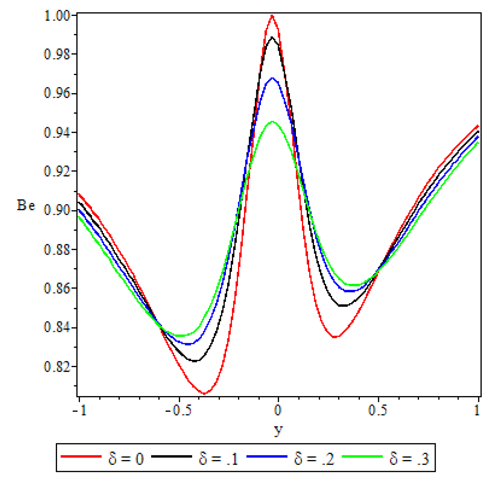
B e = N h N h + N f .
According to Bejan [19], the Bejan number varies from 0 to 1, where B e = 0 tells us that the irreversibility due fluid viscous dissipation and porosity dominate, whereas, B e = 1 2 indicates that the irreversibility due fluid viscous dissipation and porosity is equal to irreversibility due heat transfer in the entropy production, and B e = 1 reveals that irreversibility due to heat transfer dominates.

4. Method of Solution

The system of nonlinear ordinary differential Equations (6)–(7), with boundary conditions (8) is solved numerically by the spectral quasilinearisation method (SQLM). Firstly, quasilinearisation iteration scheme is applied to linearize the system. Bellman and Kalaba [20] introduced this quasilinearisation method (QLM) which is a generalisation of the Newton-Raphson method for solving nonlinear boundary value problems. The quasilinearisation technique is utilised to linearise the equations before they are solved using the SQLM. We let
F = e α θ f + 6 Ω f f 2 α e α θ f θ δ e α θ f + G r θ S i n ( ω ) + G = 0 ,
H = θ + B r f 2 ( e α θ + 2 Ω f 2 ) + δ B r e α θ f 2 + λ ( 1 + ϵ θ ) m e x p θ 1 + ϵ θ = 0 .
Reducing the non-linear Equations (13) and (14) to linear equations using QLM, we let f r , θ r be an approximate current solution and f r + 1 , θ r + 1 be an improved solution of the system of equations. Assuming | f r + 1 f r | 1 and | θ r + 1 θ r | 1 , we linearise the equations by expanding F and H using Taylor series expansion. We have
a 2 , r f r + 1 + a 1 , r f r + 1 + a 0 , r f + b 1 , r θ r + 1 + b 0 , r θ r + 1 = R 1 , r ,
c 2 , r θ r + 1 + c 1 , r θ r + 1 + c 0 , r θ + d 1 , r f r + 1 + d 0 , r f r + 1 = R 2 , r ,
with new non−dimensional boundary conditions
y = 1 : f r + 1 = β 1 e α θ r f r , θ r + 1 = B i θ r , y = 1 : f r + 1 = β 2 e α θ r f r , θ r + 1 = B i θ r ,
where
a 2 , r = F f r = e α θ r + 6 Ω f r 2 , a 1 , r = F f r = α e α θ r θ r + 12 Ω f r f r , a 0 , r = F f r = δ e α θ r , b 1 , r = F θ r = α e α θ r f r , b 0 , r = F θ r = α e α θ r f r + α 2 e α θ r f r θ r α δ e α θ r f r + G r S i n ( ω ) , c 2 , r = H θ r = 1 , c 1 , r = H θ r = 0 , c 0 , r = H θ r = α B r e α θ r f r 2 α δ B r e α θ r f r 2 + λ ( 1 + ϵ θ ) m 2 e x p θ 1 + ϵ θ ( m ϵ ( 1 + ϵ θ ) + 1 ) , d 1 , r = H f r = 2 B r e α θ r f r + 8 B r Ω f r 3 , d 0 , r = H f r = 2 δ B r e α θ r f r , R 1 , r = e α θ r f r α e α θ r θ r f r + 6 Ω f r f r 2 δ e α θ r f r , R 2 , r = B r f r 2 ( e α θ r + 2 Ω f r 2 ) + δ B r e α θ r f r 2 + λ ( 1 + ϵ θ r ) m e x p θ 1 + ϵ θ r .
The QLM iteration scheme (15) and (16) is solved using the Chebyshev spectral collocation method. The approximations for the unknown functions are done by using Chebyshev interpolating polynomials in such a way that they are collocated at the Gauss-Lobatto points defined as
τ i = c o s π i N , i = 0 , 1 , 2 , . . . , N ,
where N is the number of collocation points. The functions f r + 1 and θ r + 1 at the collocation points are represented by
f r + 1 ( τ ) = k = 0 N f r + 1 ( τ k ) T k ( τ i ) , θ r + 1 ( τ ) = k = 0 N θ r + 1 ( τ k ) T k ( τ i ) , i = 0 , 1 , 2 , . . . , N ,
where T k is the k t h Chebyshev polynomial defined by
T k ( τ ) = c o s ( k c o s 1 τ ) .
The derivatives of f r + 1 and θ r + 1 at the collocation points are represented as
d p f r + 1 d y p = k = 0 N D k i p f r + 1 ( τ k ) , d p θ r + 1 d y p = k = 0 N D k i p θ r + 1 ( τ k ) ,
where p is the order of differentiation and D is the Chebyshev spectral differential matrix of order ( N + 1 ) × ( N + 1 ) . We substitute Equations (19)–(22) into Equations (15)–(16) to obtain
a 2 , r D 2 + a 1 , r D + a 0 , r I F r + 1 + b 1 , r D + b 0 , r I Θ r + 1 = R 1 , r ,
d 1 , r D + d 0 , r I F r + 1 + c 2 , r D 2 + c 1 , r D + c 0 , r I Θ r + 1 = R 2 , r ,
where I is ( N + 1 ) × ( N + 1 ) identity matrix.
Putting Equations (23) and (24) in a matrix form we get
A 11 A 12 A 21 A 22 F r + 1 Θ r + 1 = R 1 , r R 2 , r ,
where
A 11 = a 2 , r D 2 + a 1 , r D + a 0 , r I , A 12 = b 1 , r D + b 0 , r I , A 21 = d 1 , r D + d 0 , r I , A 22 = c 2 , r D 2 + c 1 , r D + c 0 , r I , F r + 1 = [ f r + 1 ( τ 0 ) , f r + 1 ( τ 1 ) , f r + 1 ( τ 0 ) , . . . , f r + 1 ( τ i 1 ) , f r + 1 ( τ i ) ] T , Θ r + 1 = [ θ r + 1 ( τ 0 ) , θ r + 1 ( τ 1 ) , θ r + 1 ( τ 0 ) , . . . , θ r + 1 ( τ i 1 ) , θ r + 1 ( τ i ) ] T .
The approximate solutions for F and Θ are obtained by solving the matrix system (25),
F r + 1 Θ r + 1 = A 11 A 12 A 21 A 22 1 R 1 , r R 2 , r
and we use a suitable initial approximation that satisfies the boundary conditions of Equations (6) and (7) as
f 0 ( y ) = 1 2 G y 2 G ( β 1 + β 2 ) y β 1 β 2 + 2 1 2 G ( 4 β 1 β 2 3 β 1 + 3 β 2 2 ) β 1 β 2 + 2 ,
θ 0 ( y ) = 0 .

5. Results and Discussion

Combined effects of temperature dependent viscosity, porous media permeability, Navier slip and convective boundary conditions on the flow of a reactive third grade fluid in an inclined channel have been studied. In the following discussion, we carry out a detailed thermodynamic analysis of the dependence of the fluid velocity and temperature profiles, the entropy generation and the irreversibility ratio on the various thermophysical parameters embedded in the flow system. We present the SQLM graphical solutions and provide a qualitative description of the simulated variations. Unless otherwise stated, the following parameter values are employed: α = 0.1 , Ω = 0.1 , δ = 0.1 , G r = 0.8 , ω = P i / 4 , G = 1 , B r = 0.5 , λ = 0.1 , ϵ = 0.1 , β 1 = 0.1 , β 2 = 0.1 , B i = 5.0 , and m = 0.5 . Where a parameter is not varied, these will be the default values used.

5.1. Residual Analysis

The accuracy and convergence of the SQLM were validated by performing a residual error analysis. The residual errors were calculated to gain understanding of the accuracy, as defined by
| | R e s ( f ) | | = | | e α θ f + 6 Ω f f 2 α e α θ f θ δ e α θ f + G r θ S i n ( ω ) + G | | , | | R e s ( θ ) | | = | | θ + B r f 2 ( e α θ + 2 Ω f 2 ) + δ B r e α θ f 2 + λ ( 1 + ϵ θ ) m e x p θ 1 + ϵ θ | | .
The error infinity norms, which are used to confirm the convergence of the SQLM approximations are defined by
Error ( f ) = max 0 i N F r + 1 , i F r , i , E r r o r ( θ ) = max 0 i N Θ r + 1 , i Θ r , i .
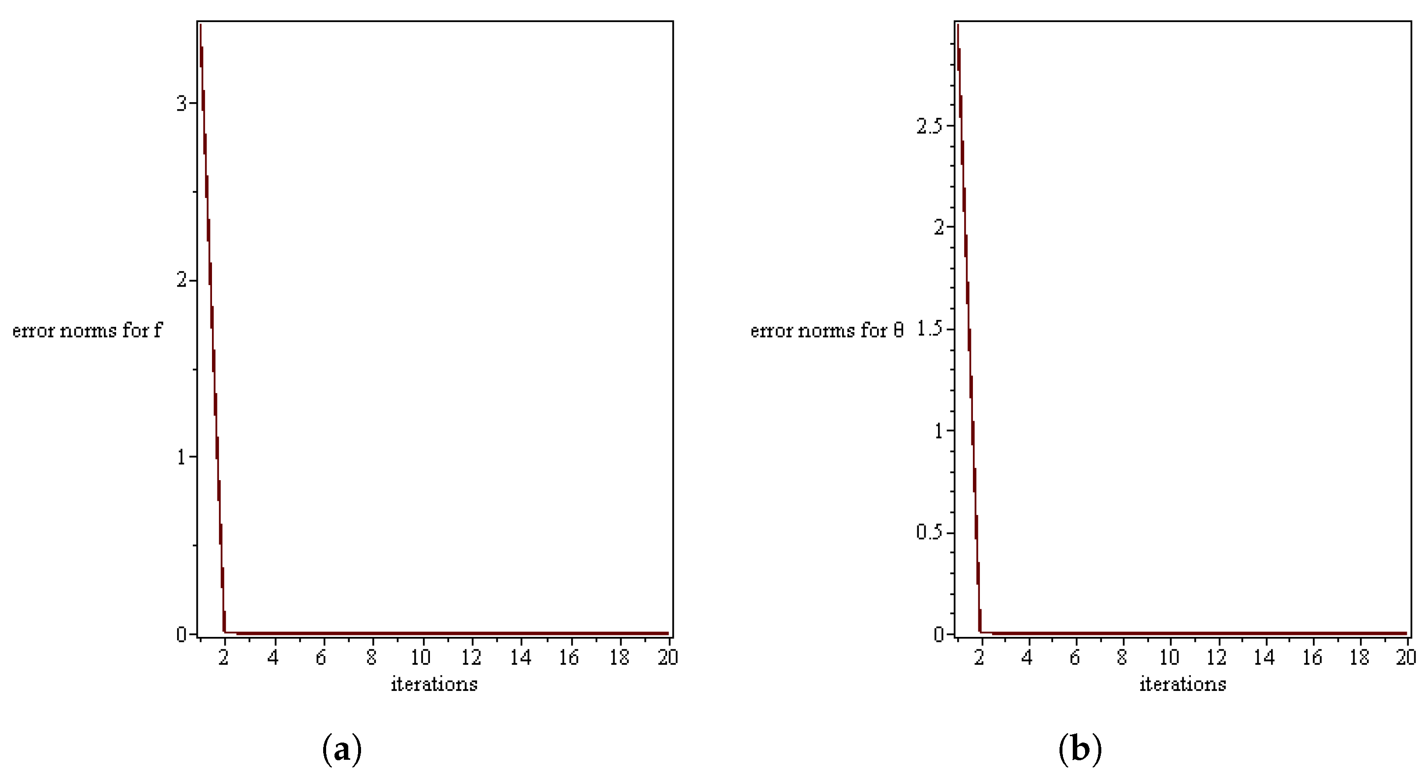
We note that the accuracy of order 10 5 for residual errors were attained after two iterations for f ( y ) and θ ( y ) as shown in Table 1, and this shows that the method is highly accurate with a good convergence rate. To have a clearer picture on the convergence rates, we plot the residual errors against the number of iterations in Figure 2. Figure 2 shows that an increase in the number of iteration results in a decrease in the error infinity norm and the method converge after two iterations.

5.2. Velocity Profile

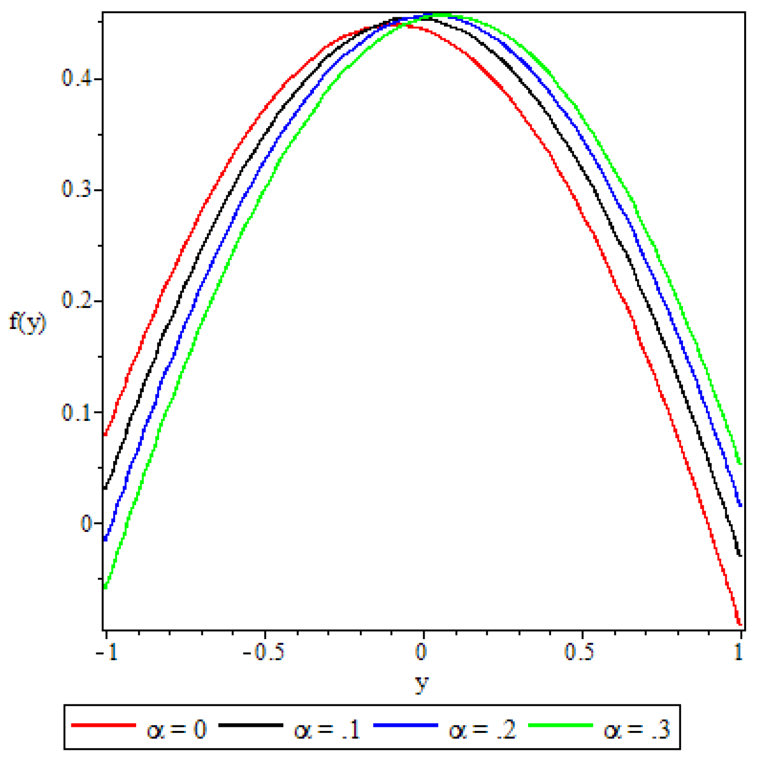
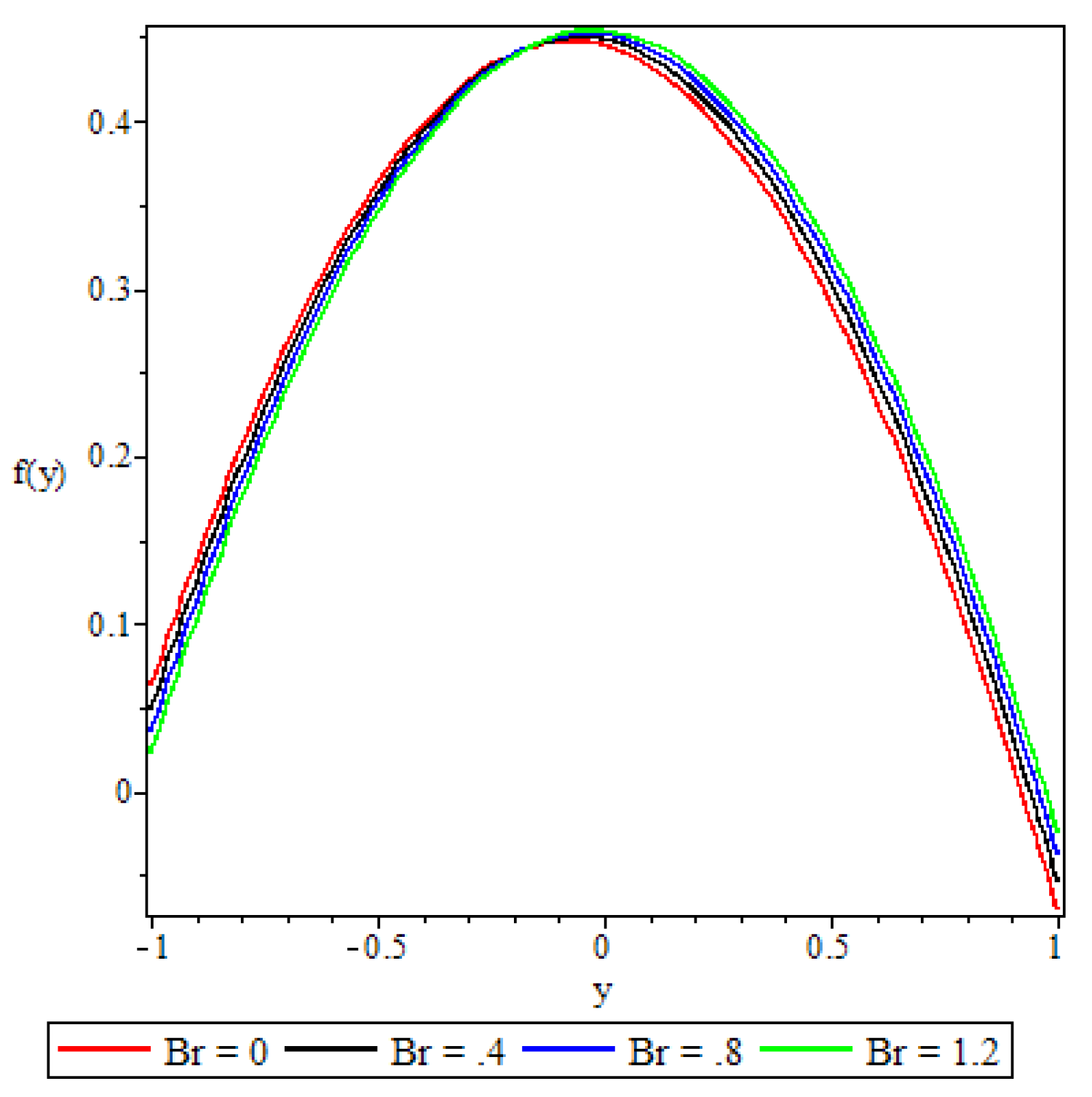
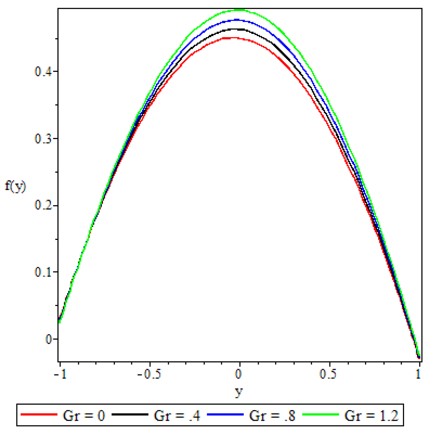
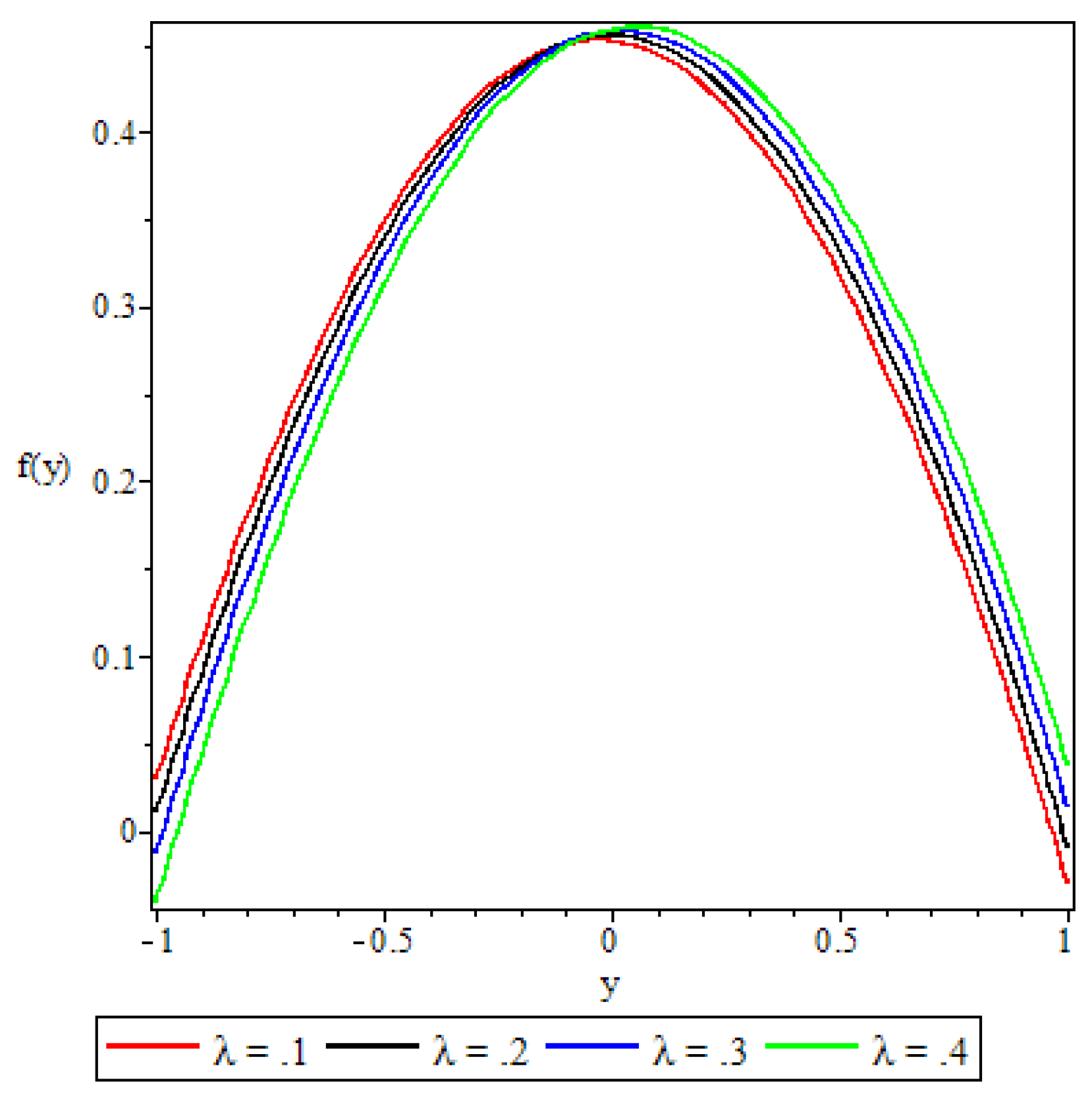
The response of the fluid velocity profile to the various flow parameters is displayed in Figure 3, Figure 4, Figure 5, Figure 6, Figure 7, Figure 8 and Figure 9. The figures reveal parabolic velocity profiles where the maximum velocity is recorded at the centre of the channel. Figure 3 reveals that from the centre of the channel towards the lower wall, the velocity profile decreases with increasing values of the variable viscosity parameter α . On the other hand, towards the upper channel wall, the figure shows the profile increasing with the variable viscosity parameter. Bearing in mind that increasing values of the variable viscosity parameter means that the fluid viscosity is reduced, this observation is to be expected since the lower wall is subjected to convective heat exchange with the ambient and on the upper wall there is a constant heat flux. As the fluid emits heat into the ambient the fluid viscosity increases resulting in velocity retardation. In Figure 4 the Brinkmann number B r is observed to affect the fluid velocity in a way similar to the variable viscosity parameter, although its effect is less pronounced as compared to the effect of the variable viscosity parameter. Since the Brinkmann number is a measure of heat flux from the channel plates to the viscous fluid, the observed similarity is to be expected.
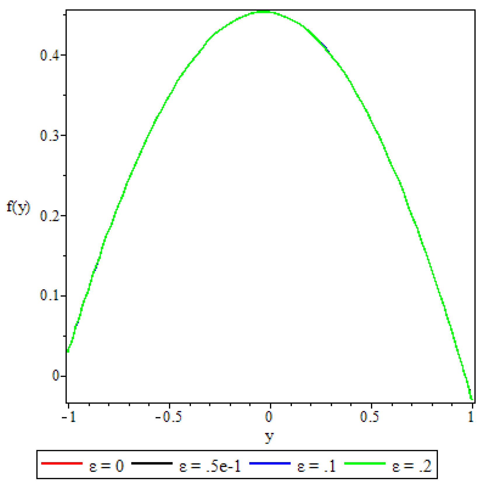
In Figure 5 we see that the activation energy parameter ϵ has no significant effect on the fluid velocity. This is explained by the fact that the activation energy parameter only enters the velocity equation implicitly through the temperature/viscosity coupling. In this way, its effects on the velocity can at best be marginal. An increase in the Grashof number G r , Figure 6, is observed to increase the fluid velocity. Variations in the Grashof number explain the buoyancy effects on the flow. Higher Grashof numbers point to increased buoyancy source terms that result in the corresponding increase in the fluid velocity as illustrated in Figure 6. The variation of the fluid velocity in response to increasing values of the Frank-Kamenetsikii parameter (chemical reaction parameter λ ) is displayed in Figure 7. An increase in the chemical reaction parameter means that the rate of chemical reaction increases, and so are the heating source terms. Figure 7 shows that towards the lower channel wall, the reaction parameter retards the velocity, whereas towards the upper wall the velocity is enhanced. At the lower wall, as explained earlier, convective heat emitted out into the ambient means that the reaction rate is suppressed and so the fluid particles have less energy to move. At the upper wall, a constant heat flux into the fluid boosts the rate of chemical reaction that results in increased excitation of the fluid particles.
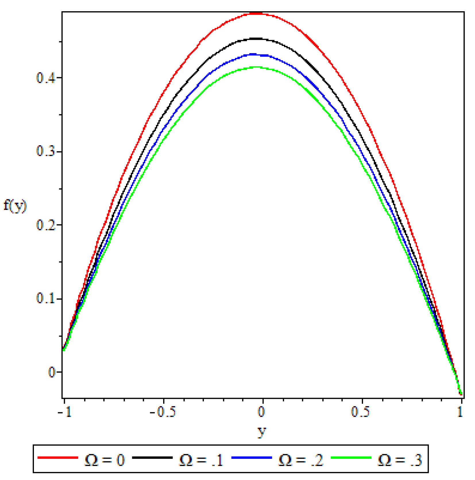
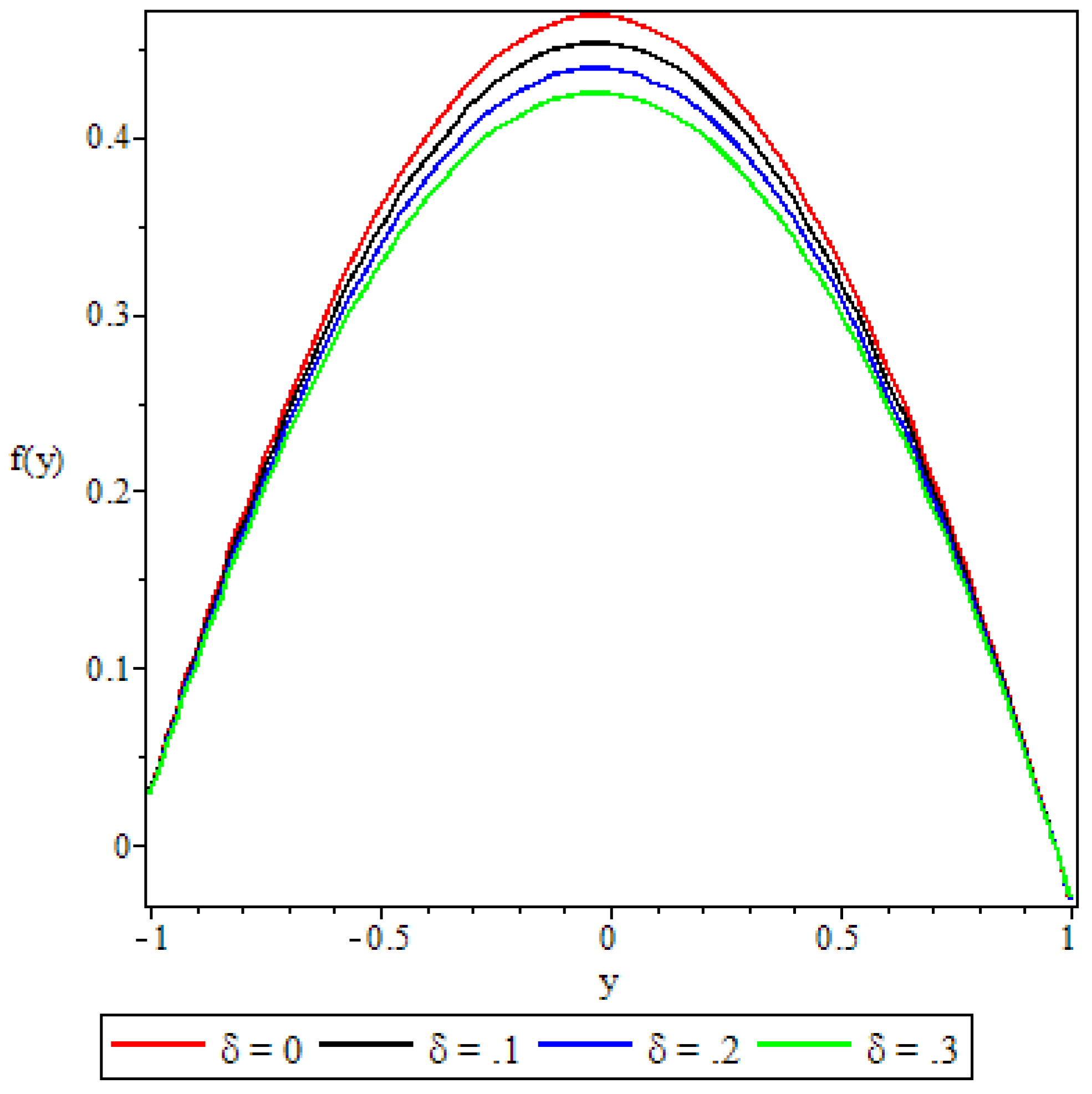
Figure 8 and Figure 9 show the flow damping effects of the third grade material parameter and the porous medium shape parameter δ , respectively. An increase in the third grade material parameter Ω results in corresponding increases in the non-Newtonian properties of the fluid, like the visco-elastic effects and others, that induce increased resistance to flow. On the other hand, increasing the porous medium shape parameter means that the pore spaces in the porous matrix are reduced, resulting in reduced porosity and hence damping the flow.

5.3. Fluid Temperature Distribution

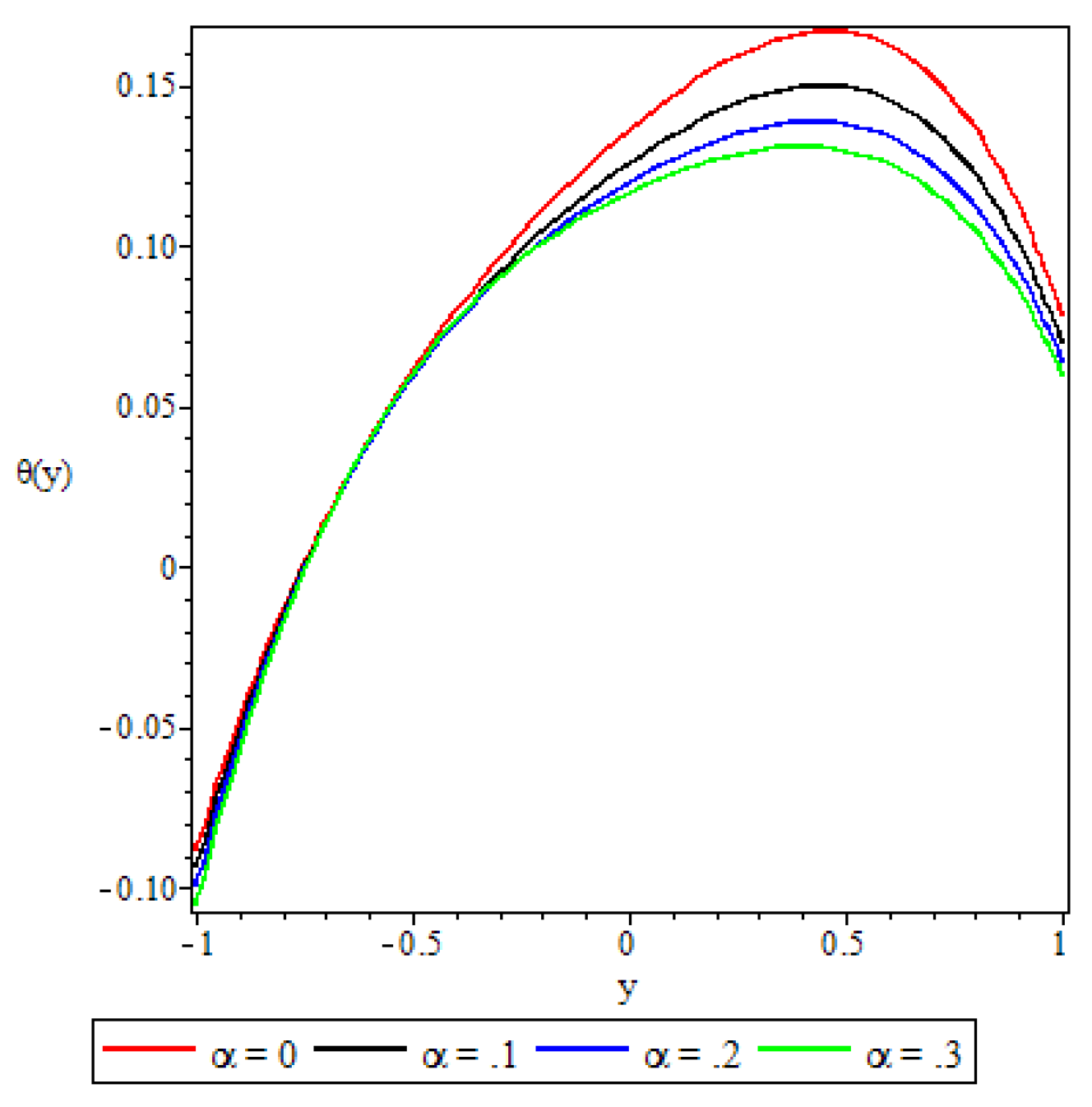
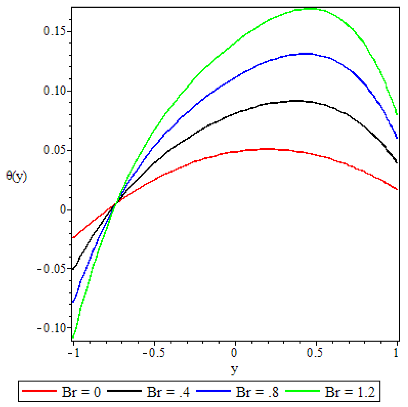
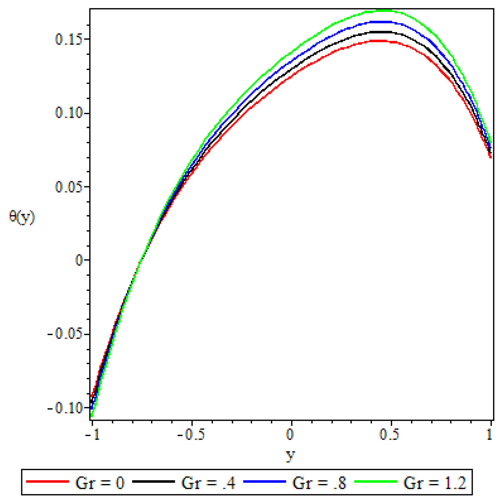
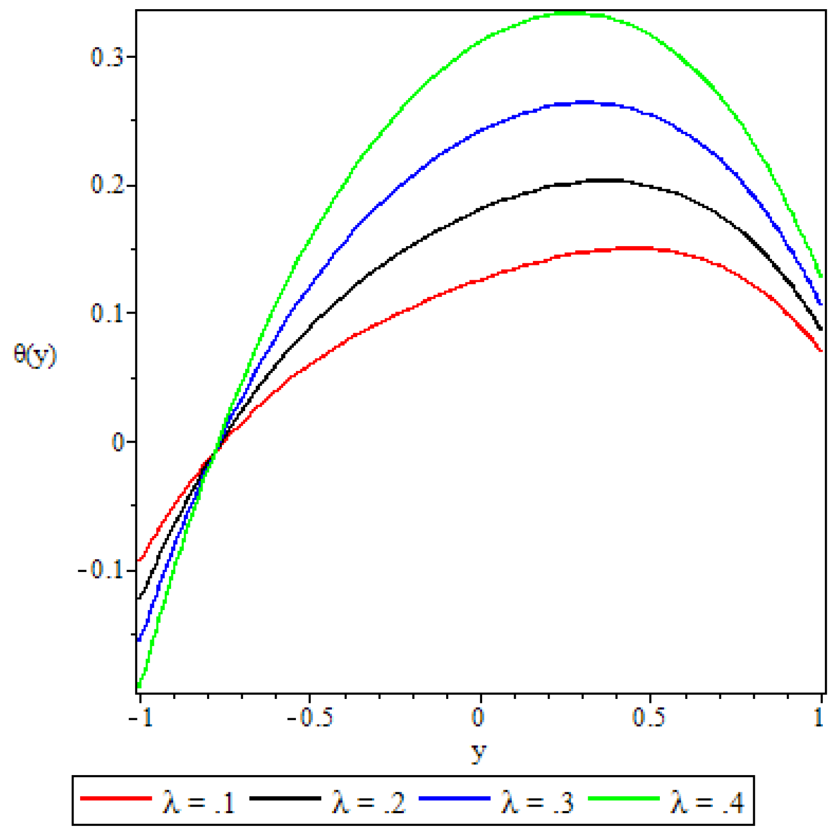
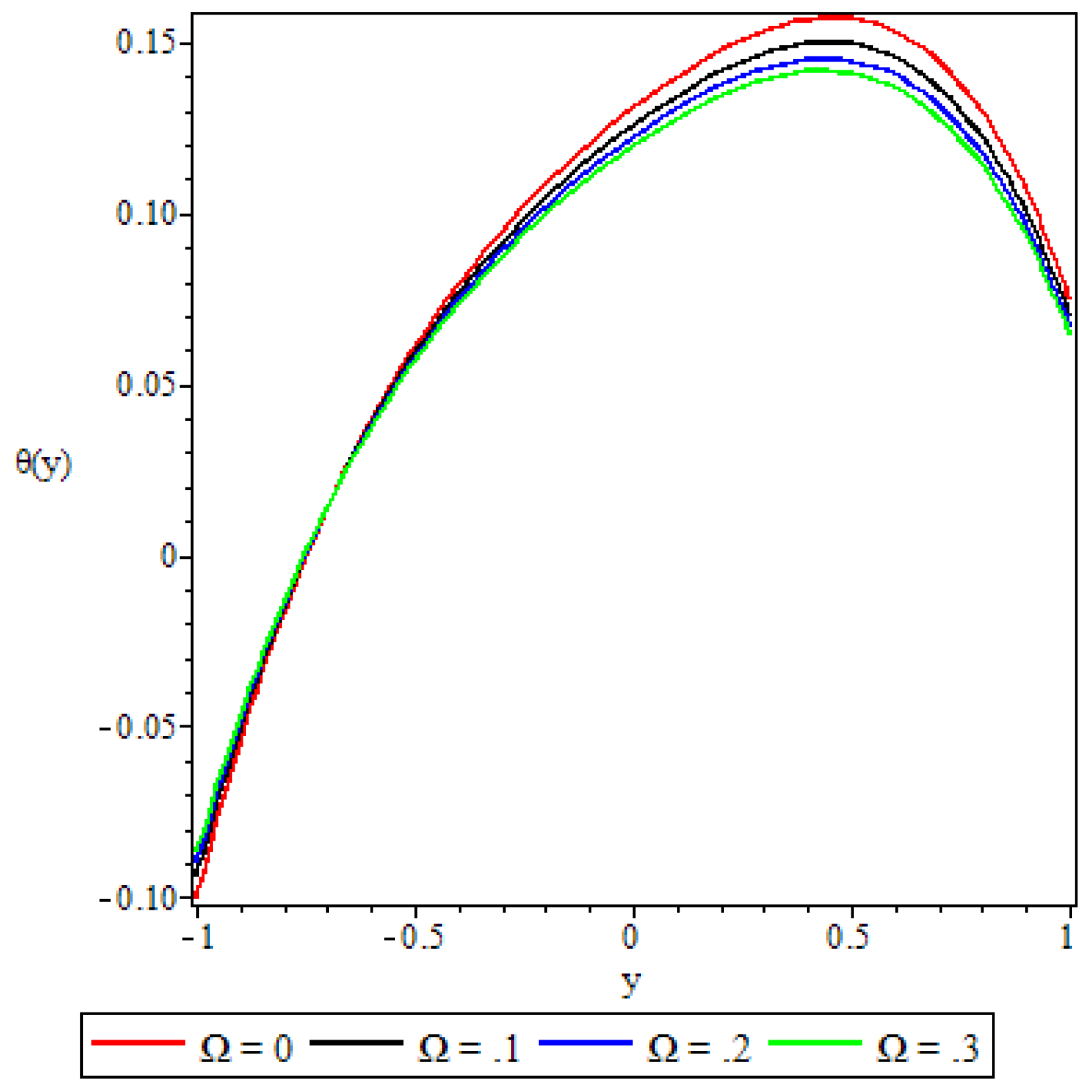
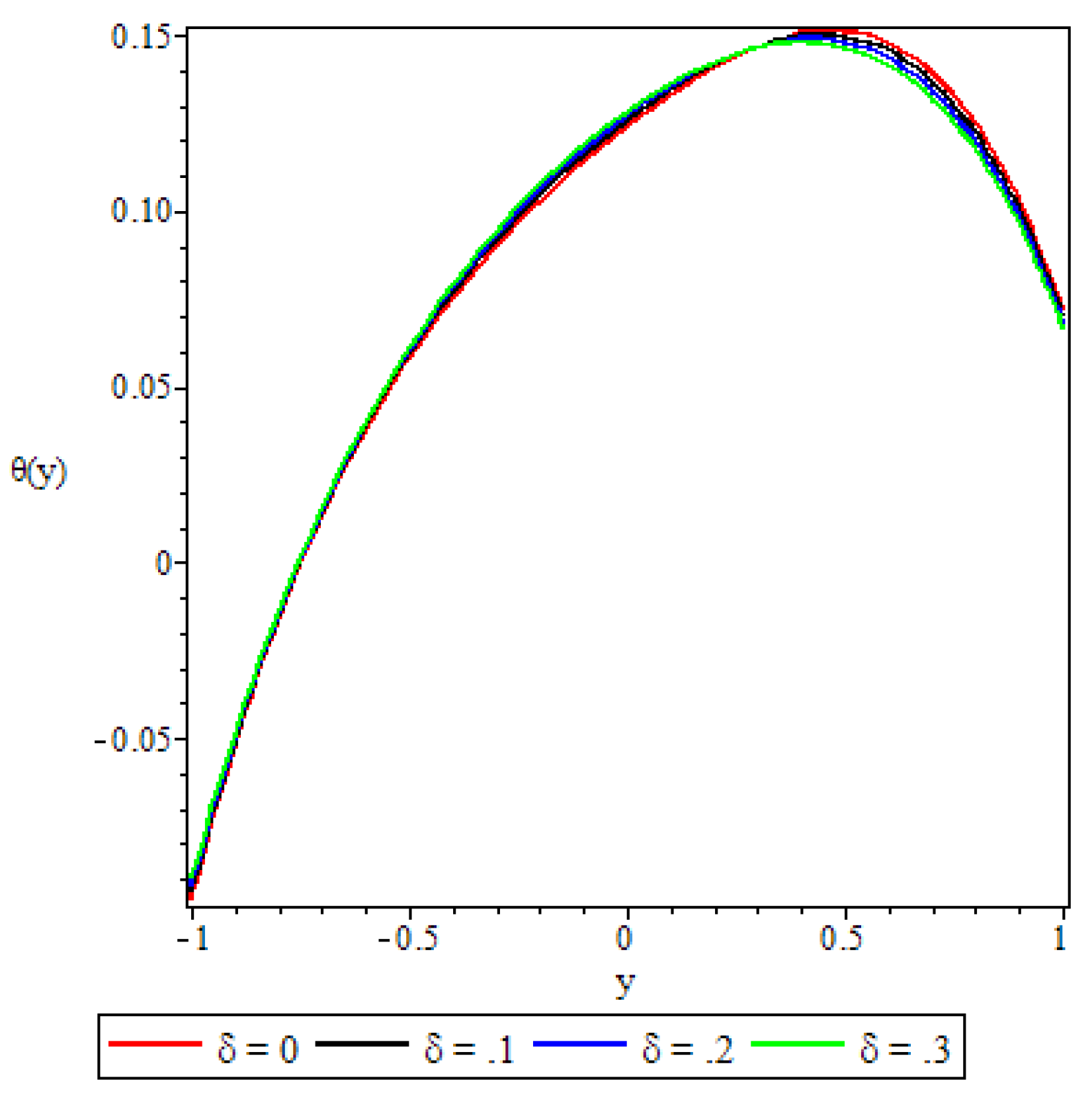
Figure 10, Figure 11, Figure 12, Figure 13, Figure 14, Figure 15 and Figure 16 display variations of the fluid temperature profile in response to various flow governing parameters. A common feature that is revealed by all these graphs is the dipping of the fluid temperature to very low levels as we move closer to and at the lower channel wall. This is attributed to the high Biot number ( B i = 5.0 ) at the lower channel wall that was set as the default value in all the computations. In general, high values of the Biot number render increased convective heat loss from the wall to the ambient, leading to a decrease in the wall temperature. Higher degrees of convective cooling at the lower wall induces a significant temperature drop in the bulk of the fluid closer to the wall.
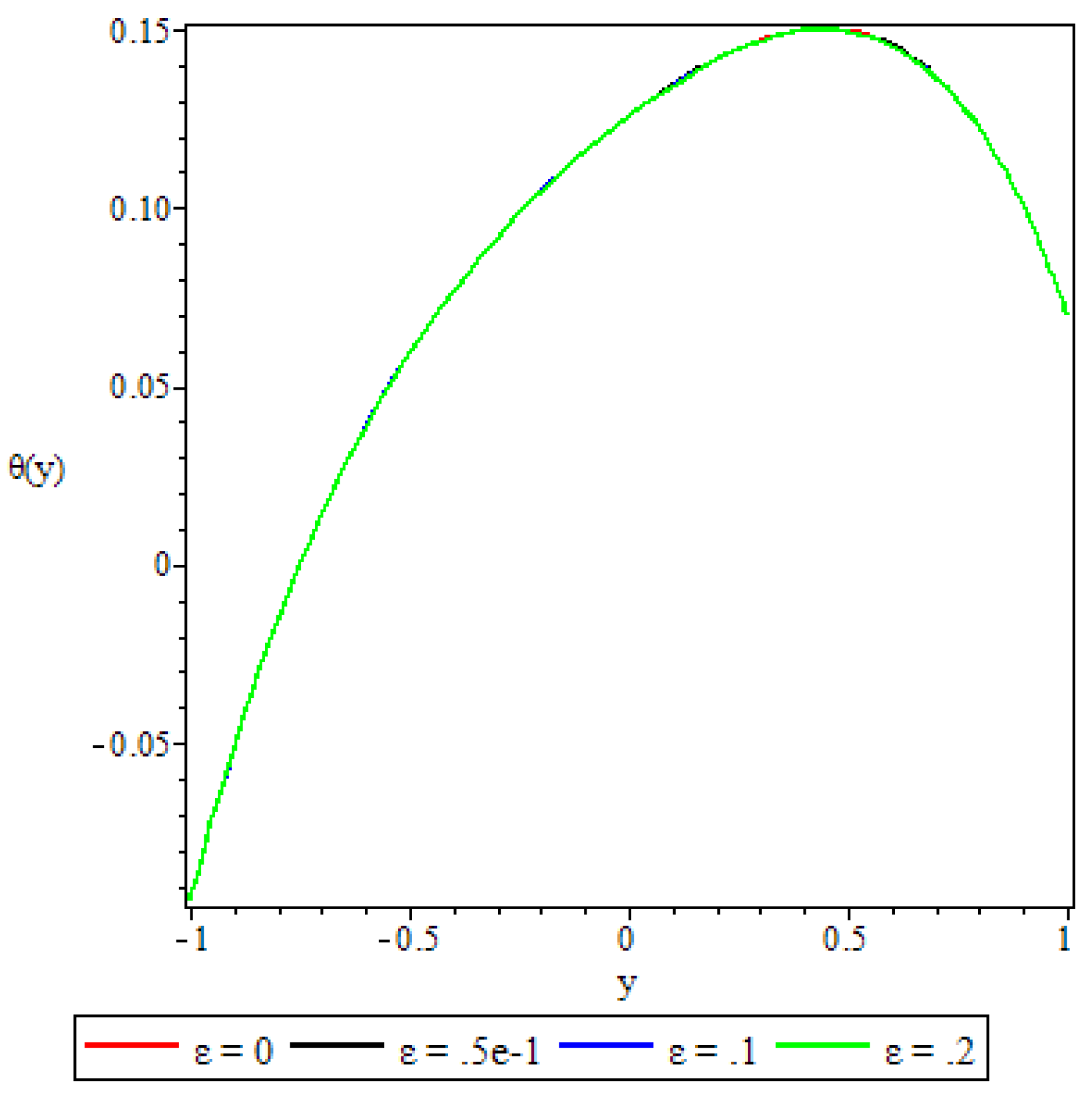
Except for Figure 12, where the activation energy parameter shows only marginal effects on the fluid temperature, and Figure 15, where the third grade material parameter retards the fluid temperature, all the other figures show the fluid temperature increasing with an increase in the values of the variable viscosity parameter, the Brinkmann number, the Grashof number, the chemical reaction parameter, and the porous medium shape parameter. The Brinkmann number and the chemical reaction parameter are observed to cause the most significant increase in fluid temperature. As alluded to earlier in the discussion, increasing values of the variable viscosity parameter means that the fluid viscosity is reduced, and this diminishes the fluid’s resistance to flow. The resultant increased fluid velocity increases the viscous heating source terms in the temperature equation, leading to the elevation of fluid temperature as depicted in Figure 10. In Figure 11, the Brinkmann number, a measure of heat flux from the channel wall into the fluid, is observed to increase the fluid temperature significantly as pointed to earlier. In Figure 13, increasing buoyancy forces lead to an increase in fluid temperature. The heat flux from the upper channel wall into the fluid leads to a volumetric thermal expansion of the fluid which induces some overturning instability in the fluid that causes the fluid particles to move faster. Due to coupling, the increased velocity increases the heating source terms in the temperature equation, resulting in enhanced fluid temperature. Figure 14 shows the fluid temperature increasing significantly with an increase in the values of the chemical reaction parameter. This phenomenon has been explained earlier in Section 5.2
In Section 5.2, we explained the reduction of fluid velocity due to increasing non-Newtonian character as measured by the third grade material parameter. The reduced velocity in turn decreases the viscous heating source terms in the temperature equation which leads to a drop in fluid temperature as shown in Figure 15. In Figure 16, except very close to the upper wall, elsewhere in the channel an increase in the porous medium shape parameter values cause a slight increase in the fluid temperature. This can be attributed to the frictional forces caused by the fluid particles as they force their way into reduced pore spaces. Close to the upper wall, reduced porosity is seen to decrease the fluid temperature. This, again, can be explained by the coupling effect via damped velocity.

5.4. Entropy Generation

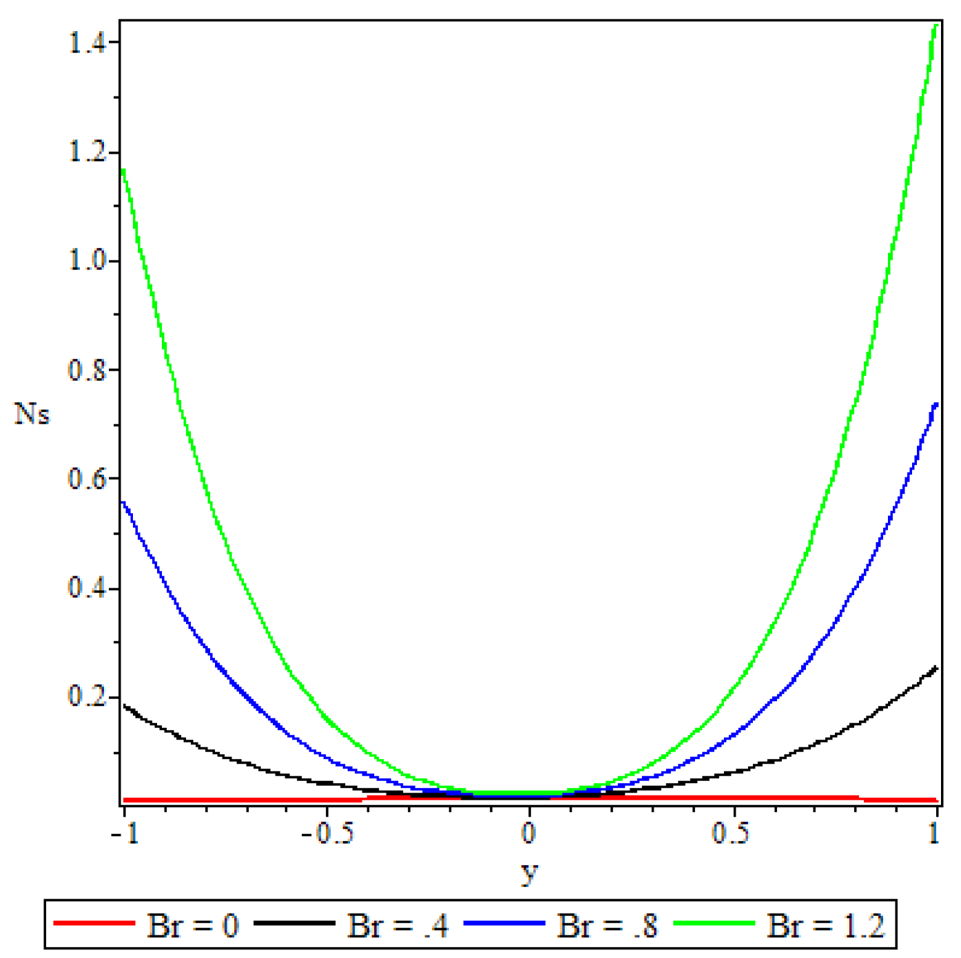
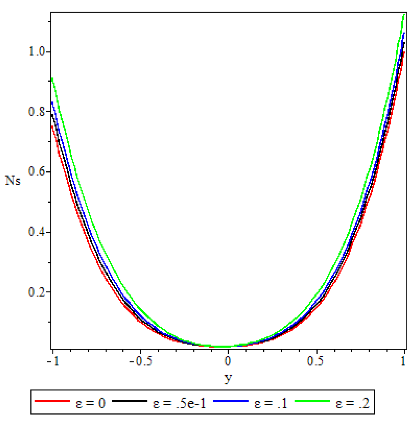
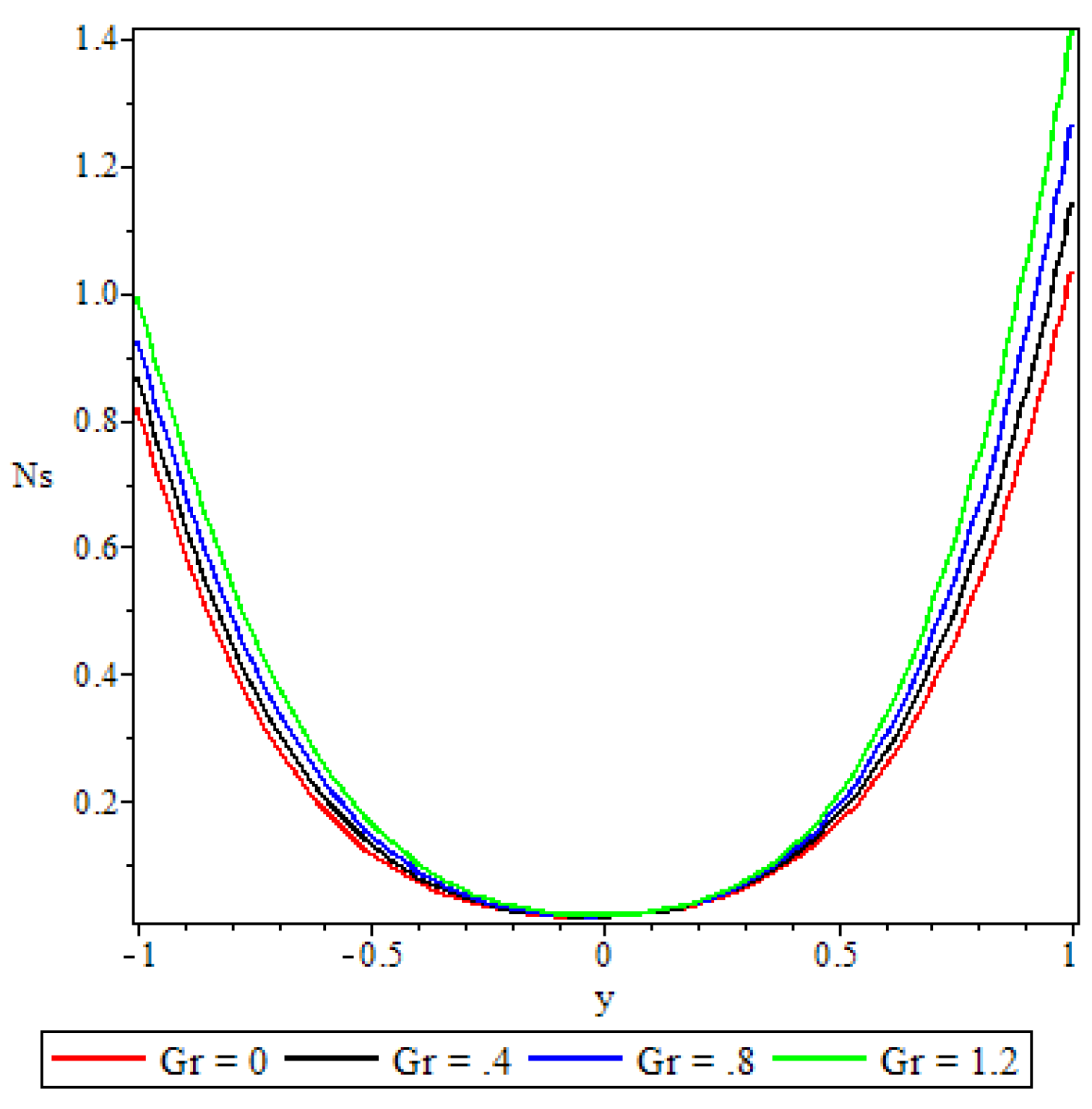
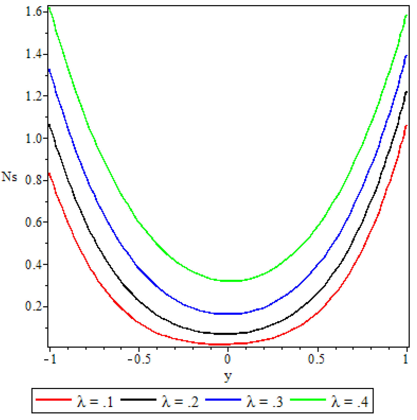
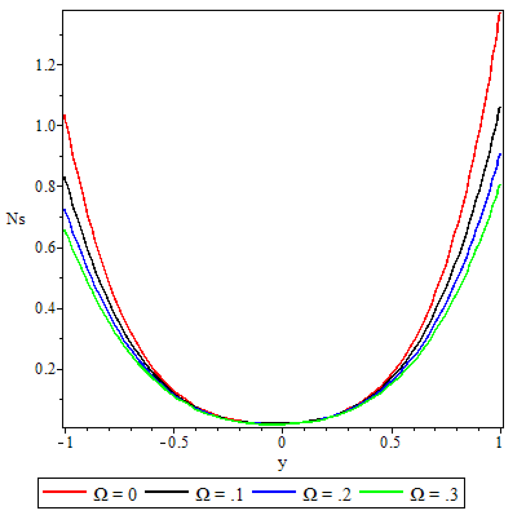
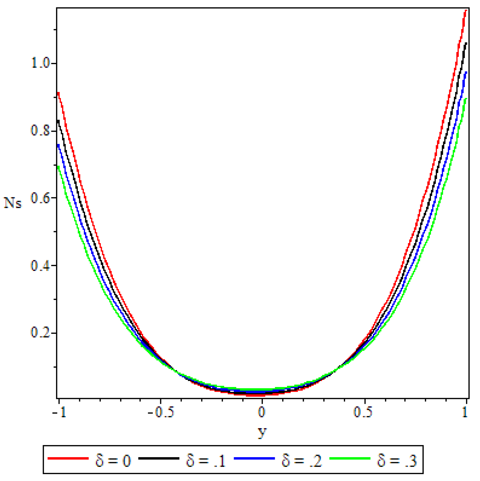
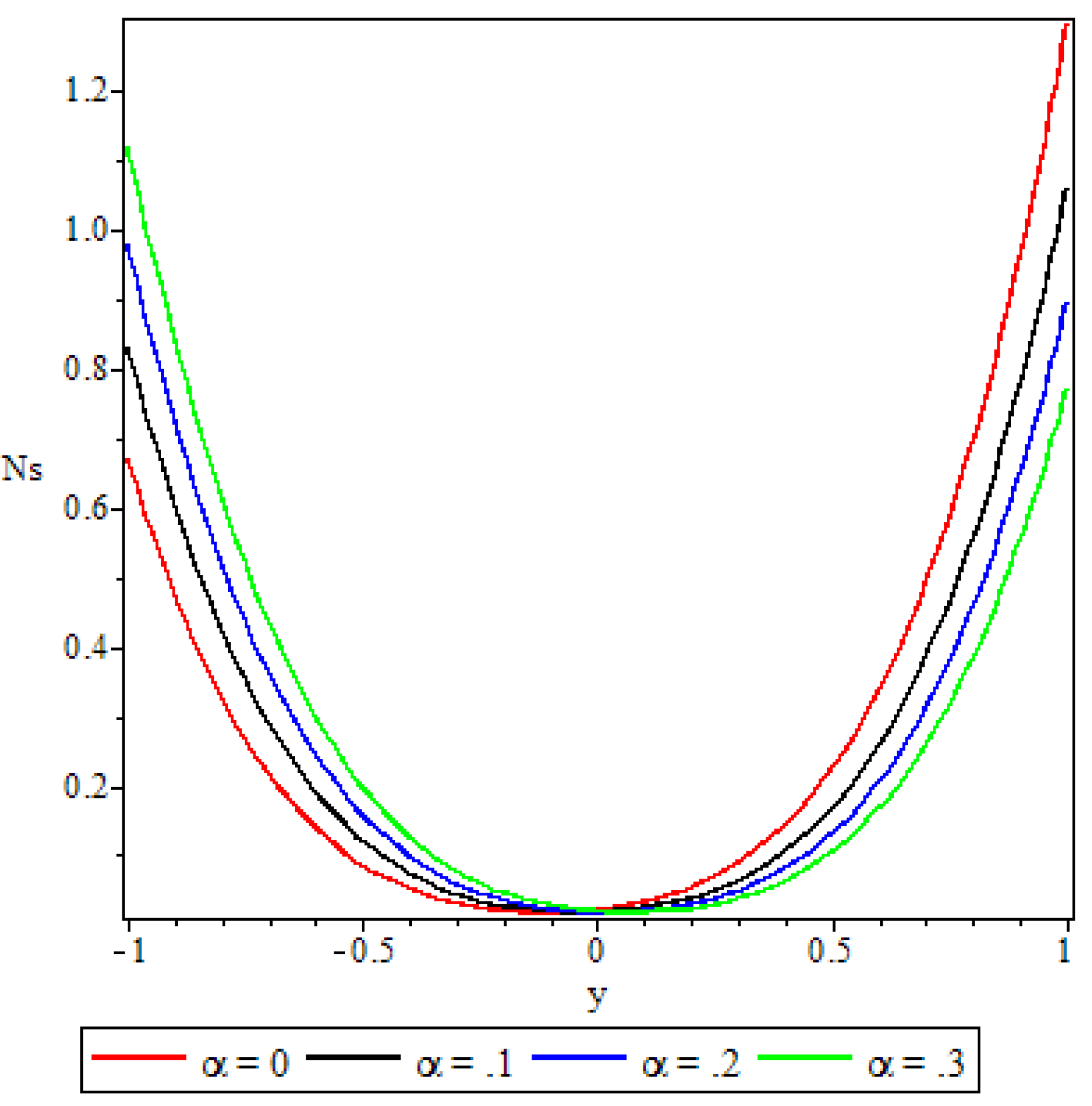
Analysis of the entropy generated in the flow is carried out with the aid of Figure 17, Figure 18, Figure 19, Figure 20, Figure 21, Figure 22, Figure 23. The figures depict parabolic entropy profiles with minimum entropy rate N s = 0 at the channel core region. Except for Figure 20, all the other figures show that the entropy generation at the core region of the channel remains unaffected by the parameter variations. Figure 17, Figure 18, Figure 19 and Figure 20 show the entropy generation rate increasing with increasing values of the Brinkmann number, the activation energy parameter, the Grashof number and the chemical reaction parameter, respectively. The most significant effects are in Figs Figure 17 and Figure 20, due to the Brinkmann number and the chemical reaction parameter. In Figure 20, the rate of entropy generation is increased throughout the entire channel including the core region. In Figure 21 and Figure 22 the third grade material parameter and the porous medium shape parameter have a retardation effect to the entropy generation rate. In the lower half of the channel, Figure 23, an increase in the variable viscosity parameter enhances the entropy generation rate, while in the upper half of the channel the variable viscosity parameter has the opposite effect. Comparing Figure 23 and Figure 3, we observe that in the region where the variable viscosity parameter decreases the fluid velocity, it enhances the rate of entropy generation. In the region where the variable viscosity parameter increases the fluid velocity, it retards the entropy generation rate.

5.5. Bejan Number

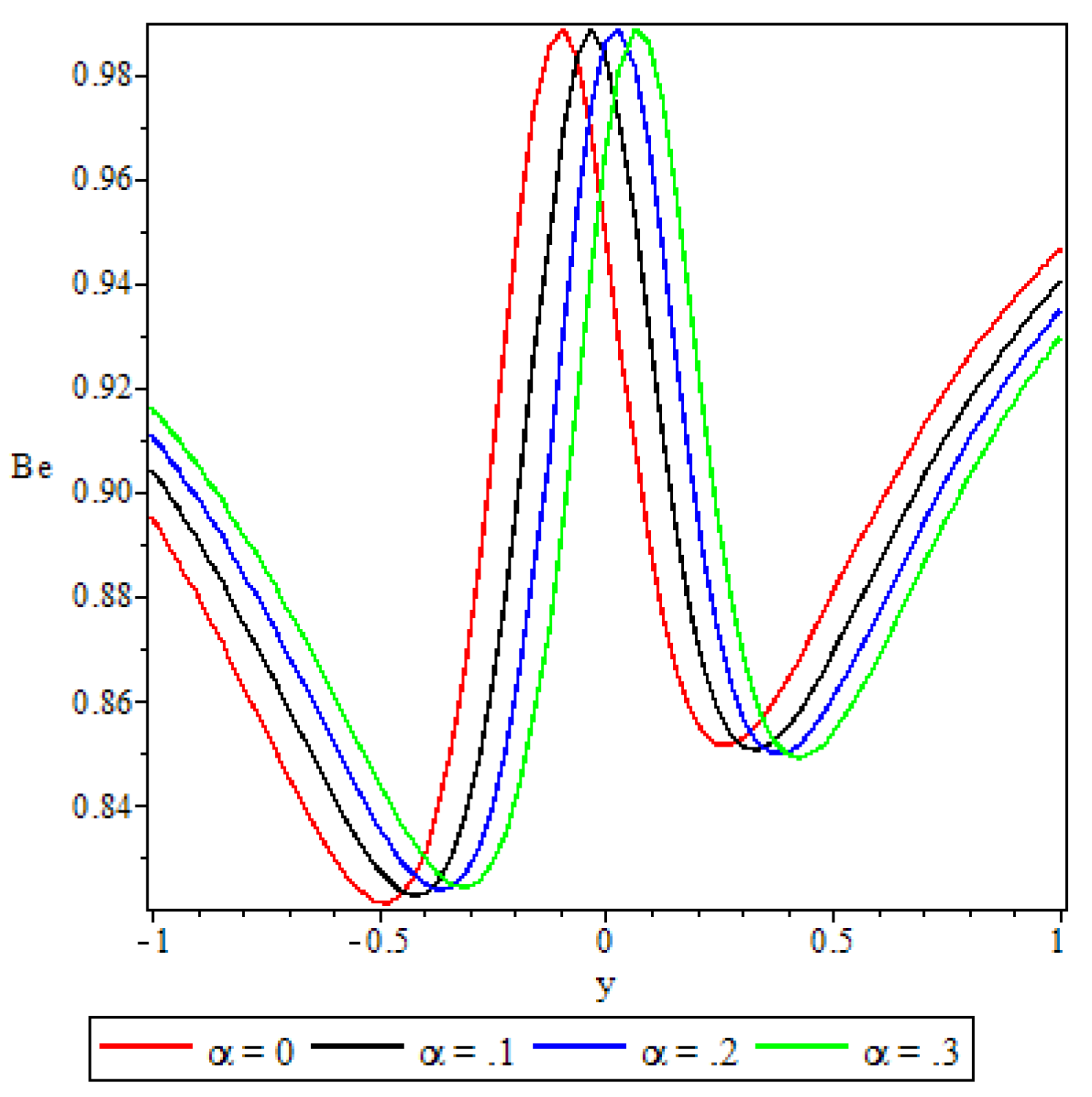
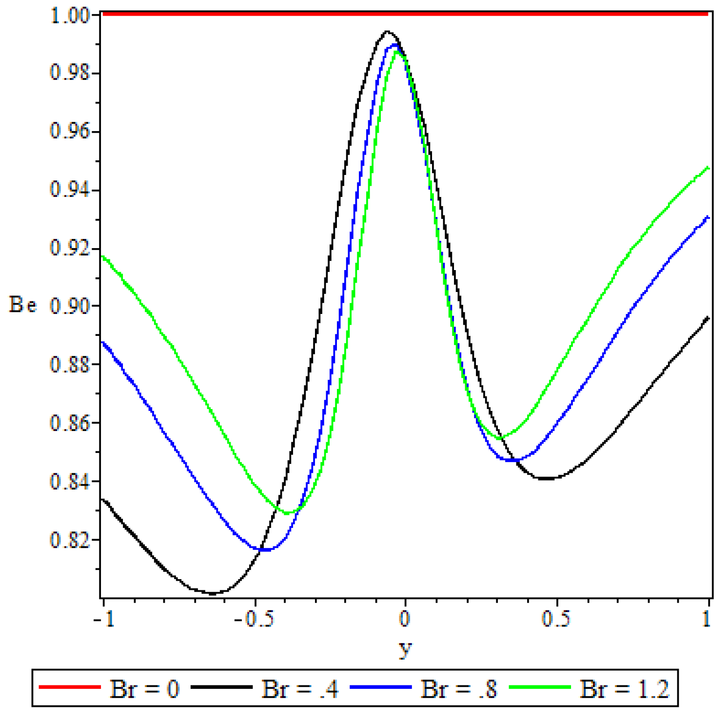
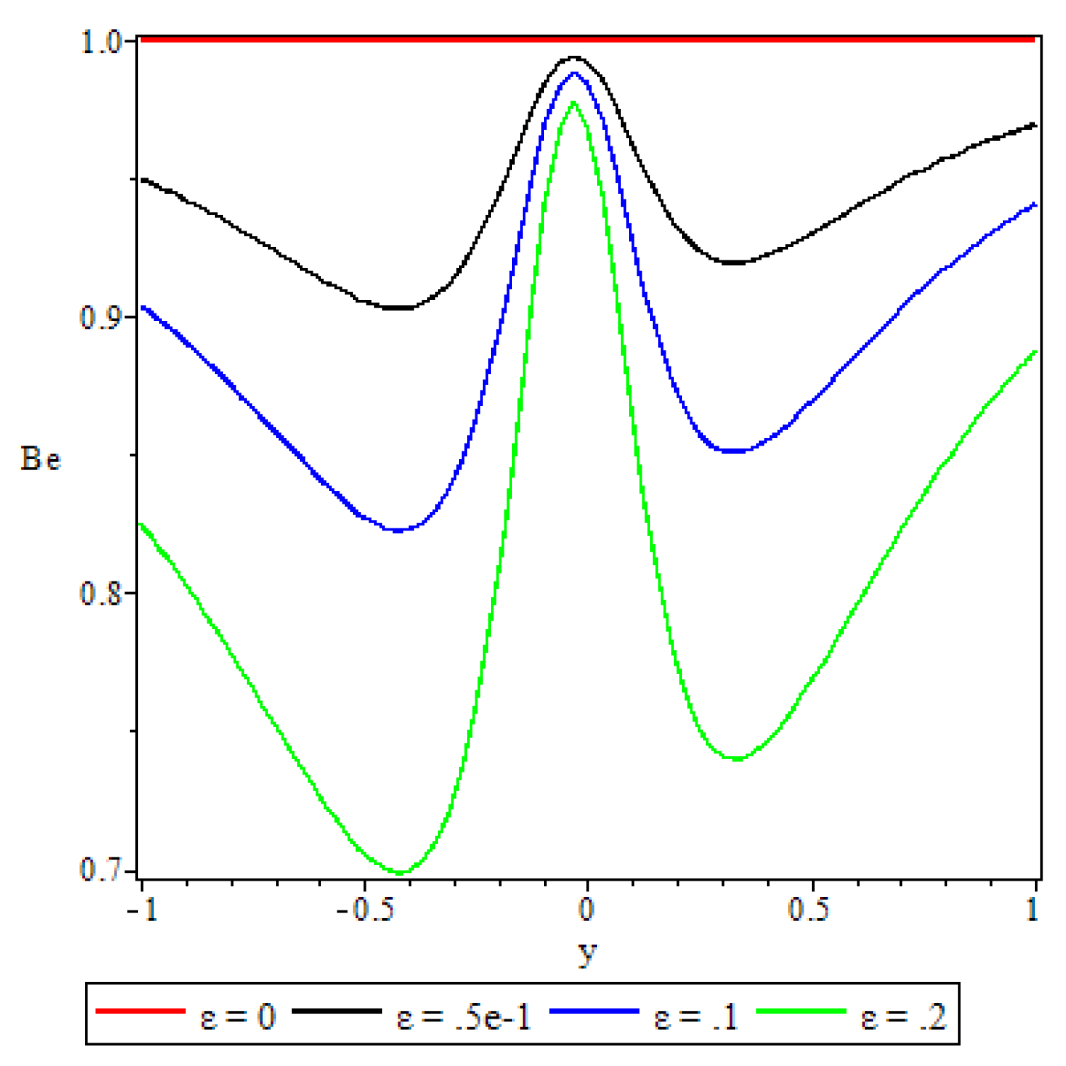
Figure 24, Figure 25, Figure 26, Figure 27, Figure 28, Figure 29 and Figure 30 demonstrate the irreversibility ratio trends in response to variation of the flow governing parameters. A striking feature displayed by all these 7 graphs is that the irreversibility ratio is maximum at the core region of the channel. This shows that, in this flow, irreversibility due to heat transfer dominates at the channel core region. Elsewhere within the channel, the graphs reveal the combined irreversibility due to viscous dissipation and porous medium porosity dominating the heat transfer irreversibility at the core of the lower half of the channel (at y = 0.5 ) and at the core of the upper half (at y = 0.5 ). Figure 24 shows that as the variable viscosity parameter is increased, from y = 1 to y = 0.5 the Bejan number increases and in the next quarter of the channel the opposite effect happens. From the centre of the channel to y = 0.5 the Bejan number increases and in the last quarter of the channel it is retarded. An interesting observation in Figure 25 is that the irreversibility ratio is constant at Be=1 throughout the channel when B r = 0 . The same observation is made in Figure 26 when ϵ = 0 . As the Brinkmann number increases, the Bejan number increases in the lower quarter of the channel in Figure 25. In the same graph, from y = 0.5 to y = 0.5 , the Bejan number decreases with the Brinkmann number, and in the upper quarter it is enhanced. In Figure 26, increasing values of the activation energy parameter diminishes the Bejan number in both the lower half and the upper half of the channel.
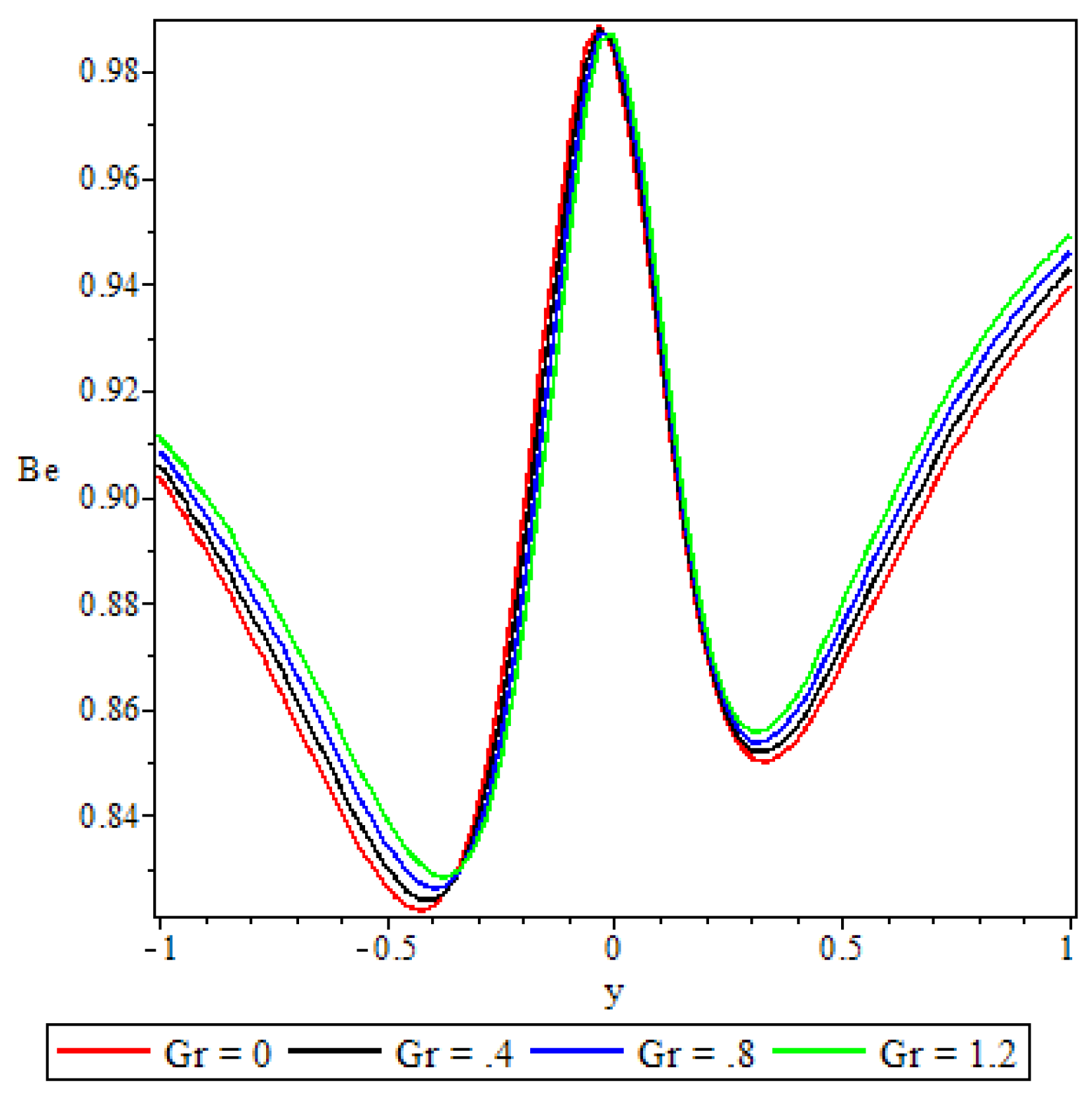
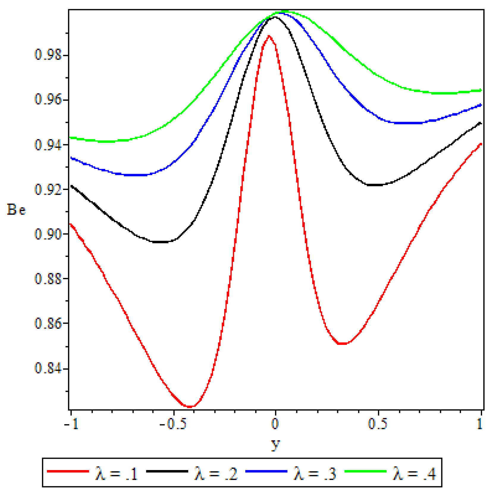
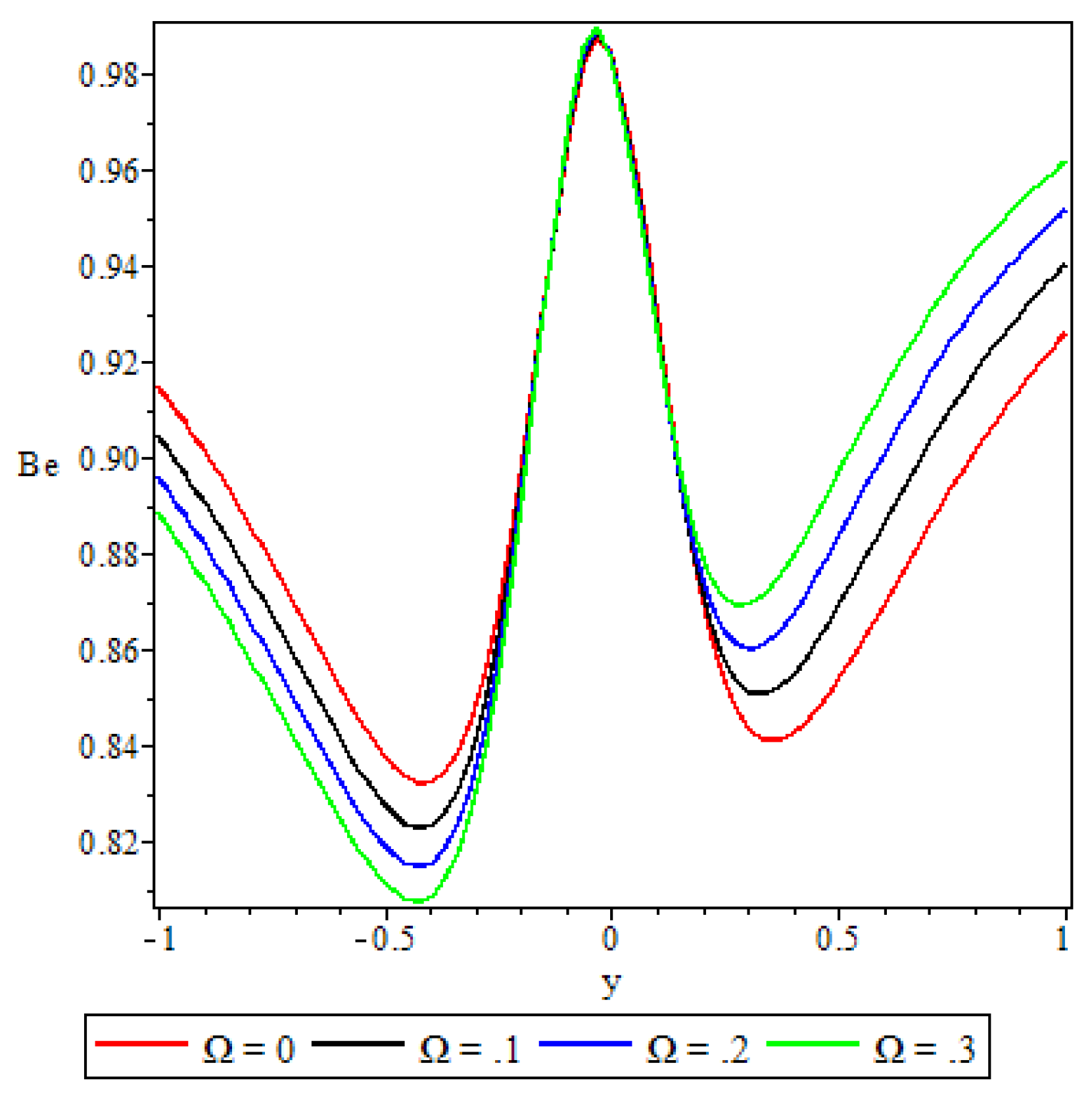
The effects of the Grashof number on the irreversibility ratio, Figure 27, mirrors those of the Brinkmann number, albeit at a less pronounced intensity. In Figure 28, an increase in the chemical reaction parameter reveals effects that are exactly opposite of the effects of the activation energy parameter described in Figure 26. In Figure 29, an increase in the non-Newtonian properties of the fluid decreases the Bejan number in the lower half of the channel, whereas in the upper half of the channel it is enhanced. Figure 30 shows that increasing the porous medium shape parameter retards the Bejan number at the core region of the channel, enhances it at the centre of both halves of the channel and retards it again as we approach the channel walls.

6. Conclusions

In this article, entropy generation analysis of a steady flow of a reactive variable viscosity third grade fluid through a porous saturated medium with Navier slip and convective boundary conditions was successfully carried out with the aid of SQLM. The numerical method was found to be highly accurate and convergent. Graphical analysis of the response of the velocity and temperature distributions, entropy generation rate and irreversibility ratio to the various parameters embedded in the flow system revealed that:
  • The temperature dependent viscosity, the Brinkmann number and the chemical reaction parameter have a retardation effect on the fluid velocity in the lower half of the channel that is subjected to convective heat exchange with the ambient, while the opposite effect is observed in the upper half of the channel that is subjected to a constant heat flux.
  • The non-Newtonian properties of the fluid and the porous medium shape factor parameter were observed to have a damping effect on the fluid velocity, while the buoyancy forces were observed to have the opposite effect.
  • The fluid temperature profile was observed to increase with an increase in the Brinkmann number, the buoyancy force, and the chemical reaction parameter, whereas the variable viscosity parameter and the third grade material parameter had a retardation effect.
  • A parabolic entropy generation rate profile was observed with minimum entropy N s = 0 at the channel core region.
  • Parameters either increase or decrease the entropy generation rate elsewhere in the channel but at the core region of the channel it remained unaffected by all the parameters except the chemical reaction parameter.
  • The irreversibility ratio was observed to be maximum at the channel core region indicating dominance of heat transfer irreversibility over the combined viscous dissipation and porosity irreversibility.
  • Elsewhere in the channel parameters revealed varied effects on the Bejan number but in general irreversibility due to viscous dissipation and porosity was found to dominate heat transfer irreversibility at the core region of either half of the channel.
These observed interesting manifestations will no doubt inform optimal system regulation criteria for entropy generation minimization in thermomechanical systems to achieve energy utilization efficiency. There is growing demand for economical and maintainable systems across the globe. Most industrial and engineering flow processes and thermal systems are unable to work at optimal level due to entropy generation. Since entropy generation is a measure of the destruction of accessible work of the systems, the determination of entropy generation is thus extremely vital for upgrading system performance. Our study is a theoretical model through which the factors (or parameters) that contribute to entropy generation can be identified so that their effects can be minimized through intelligent regulation so that the flow system efficiency can be maximised. Moreover, with the global technological advancements on non-Newtonian fluids, the theoretical results will provide guidance on improving, conserving and upgrading several designs in industrial thermo-fluid systems.

Author Contributions

This work is part of the first author’s PhD research under the supervision of the second and third authors. As such, the work was jointly conceptualised by three authors. The first author did the methodology, formal analysis, the draft preparation and the writing was reviewed by the second and third authors.

Funding

This research received no external funding.

Institutional Review Board Statement

Not applicable.

Informed Consent Statement

Not applicable.

Abbreviations

The following abbreviations are used in this manuscript:
SQLM Spectral Quasilinearisation Method
QLM Quasilinearisation Method

References

  1. Makinde, O.D.; Chinyoka, T.; Rundora, L. Unsteady flow of a reactive variable viscosity non-Newtonian fluid through a porous saturated medium with asymmetric convective boundary conditions. Computers & Mathematics with Applications 2011, 62, 3343–3352. [Google Scholar]
  2. Hassan, A. Thermodynamics analysis of an internal heat generating fluid of a variable viscosity reactive Couette flow. Journal of King Saud University-Science 2019, 31, 506–510. [Google Scholar] [CrossRef]
  3. MHD Couette-Poiseuille flow of variable viscosity nanofluids in a rotating permeable channel with Hall effects. Journal of Molecular liquids 2016, 221, 778–787. [CrossRef]
  4. Salem, A.M. Variable viscosity and thermal conductivity effects on MHD flow and heat transfer in viscoelastic fluid over a stretching sheet. Physics letters A 2007, 369, 315–322. [Google Scholar] [CrossRef]
  5. Okoya, S.S. Computational study of thermal influence in axial annular flow of a reactive third grade fluid with non-linear viscosity. Alexandria Engineering Journal 2019, 58, 401–411. [Google Scholar] [CrossRef]
  6. Makinde, O. Irreversibility analysis of variable viscosity channel flow with convective cooling at the walls. Canadian Journal of Physics 2008, 86, 383–389. [Google Scholar] [CrossRef]
  7. Makinde, O. Entropy-generation analysis for variable-viscosity channel flow with non-uniform wall temperature. Applied Energy 2008, 85, 384–393. [Google Scholar] [CrossRef]
  8. Mondal, H.; Mishra, S.; Kundu, P.K.; Sibanda, P. Entropy generation of variable viscosity and thermal radiation on magneto nanofluid flow with dusty fluid. Journal of Applied and Computational Mechanics 2020, 6, 171–182. [Google Scholar]
  9. Bejan, A. Second law analysis in heat transfer. Energy 1980, 5, 720–732. [Google Scholar] [CrossRef]
  10. Matthews, M.; Hill, J. Newtonian flow with nonlinear Navier boundary condition. Acta Mechanica 2007, 191, 195–217. [Google Scholar] [CrossRef]
  11. Zhu, Y.; Granick, S. Rate-dependent slip of Newtonian liquid at smooth surfaces. Physical review letters 2001, 87, 096105. [Google Scholar] [CrossRef] [PubMed]
  12. Rundora, L.; Makinde, O.D. Effects of Navier slip on unsteady flow of a reactive variable viscosity non-Newtonian fluid through a porous saturated medium with asymmetric convective boundary conditions. Journal of Hydrodynamics 2015, 27, 934–944. [Google Scholar] [CrossRef]
  13. Rundora, L.; Makinde, O.D. Unsteady mhd flow of non-newtonian fluid in a channel filled with a saturated porous medium with asymmetric navier slip and convective heating. 2018; 12, 483–493. [Google Scholar]
  14. Das, S.; Jana, R.; et al. Entropy generation in an unsteady MHD channel flow with Navier slip and asymmetric convective cooling. International Journal of Industrial Mathematics 2017, 9, 149–160. [Google Scholar]
  15. Salawu, S.O.; Fatunmbi, E.O. Inherent irreversibility of hydromagnetic third-grade reactive poiseuille flow of a variable viscosity in porous media with convective cooling. Journal of the Serbian Society for Computational Mechanics 2017, 11, 46–58. [Google Scholar] [CrossRef]
  16. Adesanya, S.O.; Falade, J.; Ukaegbu, J.; Makinde, O.D. Adomian-Hermite-Pade approximation approach to thermal criticality for a reactive third grade fluid flow through porous medium. Theoretical and Applied Mechanics 2016, 43, 133–144. [Google Scholar] [CrossRef]
  17. Frank-Kamenetskii., *!!! REPLACE !!!*; Al’bertovich, D. Diffusion and heat transfer in chemical kinetics; Plenum Press: New York, 1969. [Google Scholar]
  18. Makinde, O.D. Thermal stability of a reactive viscous flow through a porous-saturated channel with convective boundary conditions. Applied Thermal Engineering 2009, 29, 1773–1777. [Google Scholar] [CrossRef]
  19. Bejan, A. Entropy generation minimization: The new thermodynamics of finite-size devices and finite-time processes. Journal of Applied Physics 1996, 79, 1191–1218. [Google Scholar] [CrossRef]
  20. Bellman, R.E.; Kalaba, R.E. Quasilineariztion and Nonlinear Boundary-Value Problems; Elsevier: New York, 1965. [Google Scholar]
Figure 1. Schematic diagram of the problem
Preprints 109015 g001
Figure 2. (a) Error infinity norm for f ( y ) and (b) Error infinity norm for θ ( y )
Preprints 109015 g002
Figure 3. Variation of the velocity profile with the variable viscosity parameter
Preprints 109015 g003
Figure 4. Variation of the velocity profile with the Brinkman number
Preprints 109015 g004
Figure 5. Variation of the velocity profile with the activation energy parameter
Preprints 109015 g005
Figure 6. Variation of the velocity profile with the Grashof number
Preprints 109015 g006
Figure 7. Variation of the velocity profile with the Frank-Kamenetsikii parameter
Preprints 109015 g007
Figure 8. Variation of the velocity profile with the third grade material parameter
Preprints 109015 g008
Figure 9. Variation of the velocity profile with porous medium shape factor parameter
Preprints 109015 g009
Figure 10. Variation of the temperature distribution with the variable viscosity parameter
Preprints 109015 g010
Figure 11. Variation of the temperature distribution with the Brinkmann number
Preprints 109015 g011
Figure 12. Variation of the temperature distribution with the activation energy parameter
Preprints 109015 g012
Figure 13. Variation of the temperature distribution with the Grashof number
Preprints 109015 g013
Figure 14. Variation of the temperature distribution with the Frank-Kamenetsikii parameter
Preprints 109015 g014
Figure 15. Variation of the temperature distribution with the third grade material parameter
Preprints 109015 g015
Figure 16. Variation of the temperature distribution with the porous medium shape parameter
Preprints 109015 g016
Figure 17. Variation of the entropy generation with the Brinkmann number
Preprints 109015 g017
Figure 18. Variation of the entropy generation with the activation energy parameter
Preprints 109015 g018
Figure 19. Variation of the entropy generation with the Grashof number
Preprints 109015 g019
Figure 20. Variation of the entropy generation with the Frank-Kamenetsikii parameter
Preprints 109015 g020
Figure 21. Variation of the entropy generation with the third grade material parameter
Preprints 109015 g021
Figure 22. Variation of the entropy generation with the porous medium shape parameter
Preprints 109015 g022
Figure 23. Variation of the entropy generation with the variable viscosity parameter
Preprints 109015 g023
Figure 24. Variation of the Bejan number with the variable viscosity parameter
Preprints 109015 g024
Figure 25. Variation of the Bejan number with the Brinkmann number
Preprints 109015 g025
Figure 26. Variation of the Bejan number with the activation energy parameter
Preprints 109015 g026
Figure 27. Variation of the Bejan number with the Grashof number
Preprints 109015 g027
Figure 28. Variation of the Bejan number with the Frank−Kamenetsikii parameter
Preprints 109015 g028
Figure 29. Variation of the Bejan number with the third grade material parameter
Preprints 109015 g029
Figure 30. Variation of the Bejan number with the porous medium shape factor parameter
Preprints 109015 g030
Table 1. Residual errors when α = 0.1 , Ω = 0.1 , δ = 0.1 , G r = 0.8 , B r = 0.5 , λ = 0.1 , ω = ( P i / 4 ) , G = 1 , ϵ = 0.1 , β 1 = 1 , β 2 = 0.1 , B i = 5.0 , m = 0.5 .
Iterations (i) Error norm for f ( y ) Error norm for θ ( y )
1 3.4440509 2.9974374
2 0.0029493302 0.0045507285
3 7.4336997 × 10 06 4.5201419 × 10 06
4 6.3871925 × 10 10 7.9216664 × 10 11
5 1.2640627 × 10 14 6.8049385 × 10 16
6 3.977 × 10 20 4.9541979 × 10 21
7 2.5233673 × 10 25 3.4350721 × 10 26
8 4.63 × 10 30 4.332 × 10 30
9 1.01 × 10 30 2.85 × 10 30
10 1.87 × 10 30 1.52 × 10 30
11. 1.60 × 10 30 2.993 × 10 30
12 2.21 × 10 30 2.25 × 10 30
13 1.25 × 10 30 8.91 × 10 30
14 1.38 × 10 30 4.777 × 10 30
15 3.83 × 10 30 2.637 × 10 30
16 2.40 × 10 30 5.093 × 10 30
17 1.10 × 10 30 6.264 × 10 30
18 1.91 × 10 30 4.164 × 10 30
29 3.54 × 10 30 5.028 × 10 30
20 3.72 × 10 30 6.960 × 10 30
Disclaimer/Publisher’s Note: The statements, opinions and data contained in all publications are solely those of the individual author(s) and contributor(s) and not of MDPI and/or the editor(s). MDPI and/or the editor(s) disclaim responsibility for any injury to people or property resulting from any ideas, methods, instructions or products referred to in the content.
Copyright: This open access article is published under a Creative Commons CC BY 4.0 license, which permit the free download, distribution, and reuse, provided that the author and preprint are cited in any reuse.
Prerpints.org logo

Preprints.org is a free preprint server supported by MDPI in Basel, Switzerland.

Subscribe

© 2024 MDPI (Basel, Switzerland) unless otherwise stated