Submitted:
17 June 2024
Posted:
17 June 2024
You are already at the latest version
Abstract
Keywords:
1. Introduction
2. Testing Method and Materials
2.1. Pin Penetration Testing Device
2.2. Technique of Measuring Strength before Demolding
2.3. Pin penetration Test at Construction Site and Mock-Up Mold
2.4. Concrete Used in the Experiment
2.5. Compressive Strength Test
3. Results and Discussion
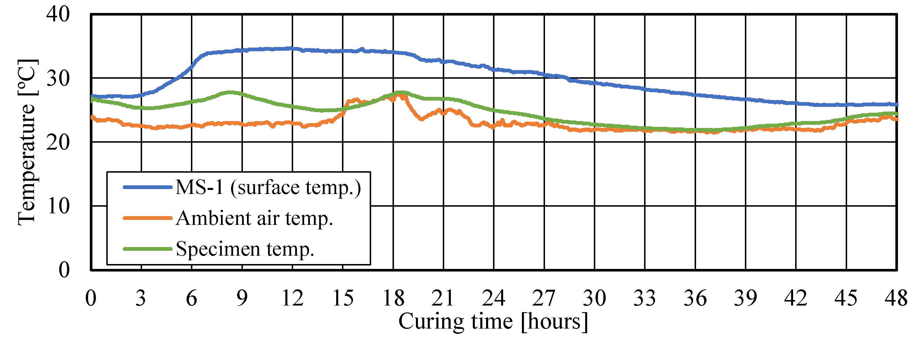
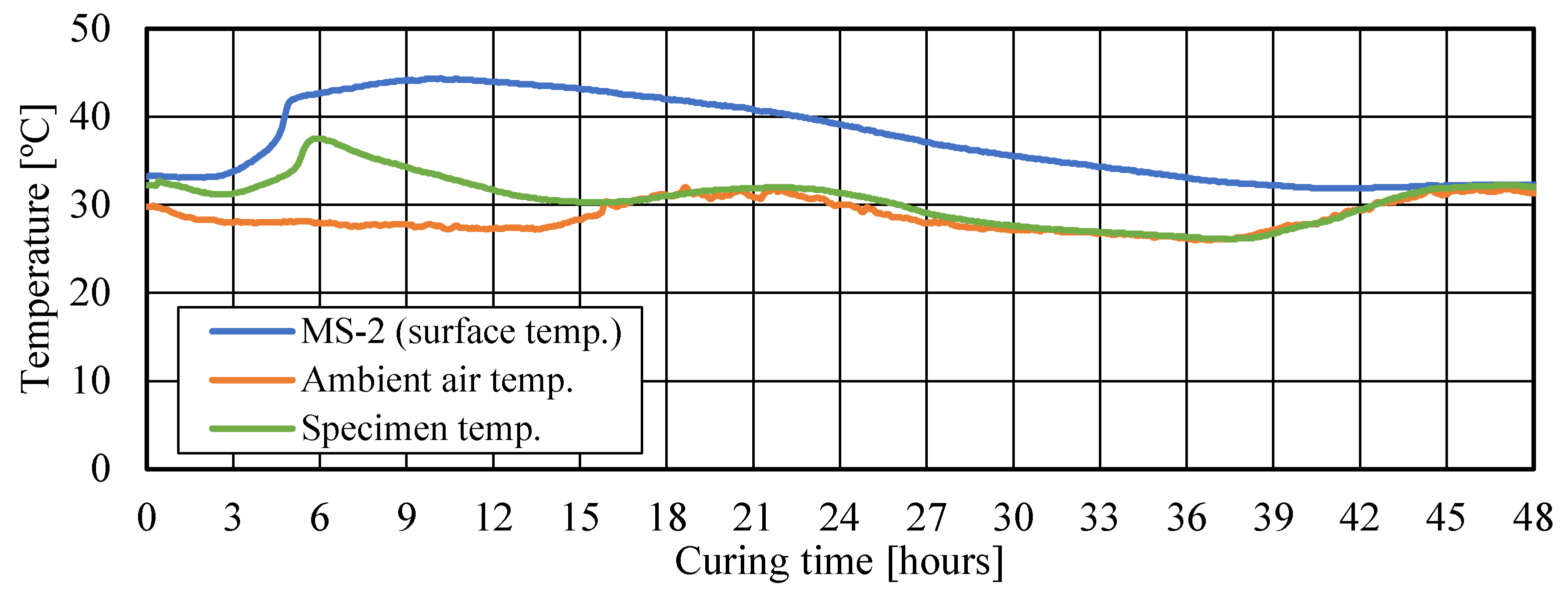
3.1. Temperature Difference between Site Concrete and Specimens
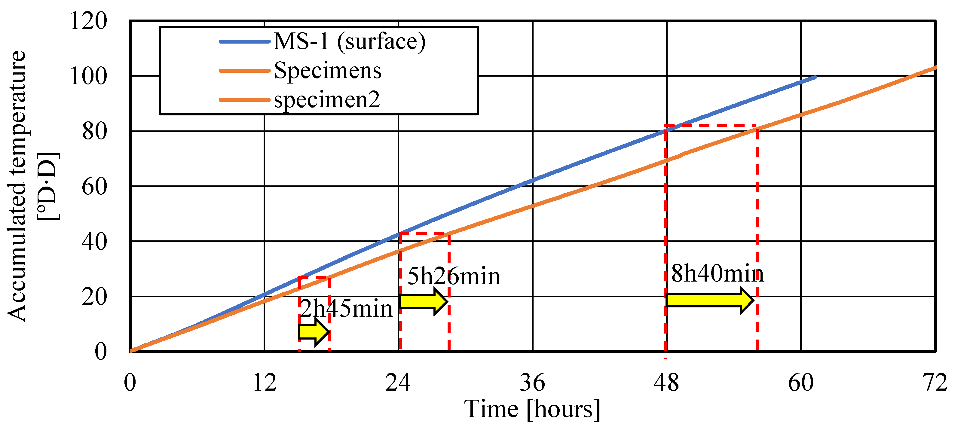
3.2. Accumulated Temperature and Strength Delaying Time
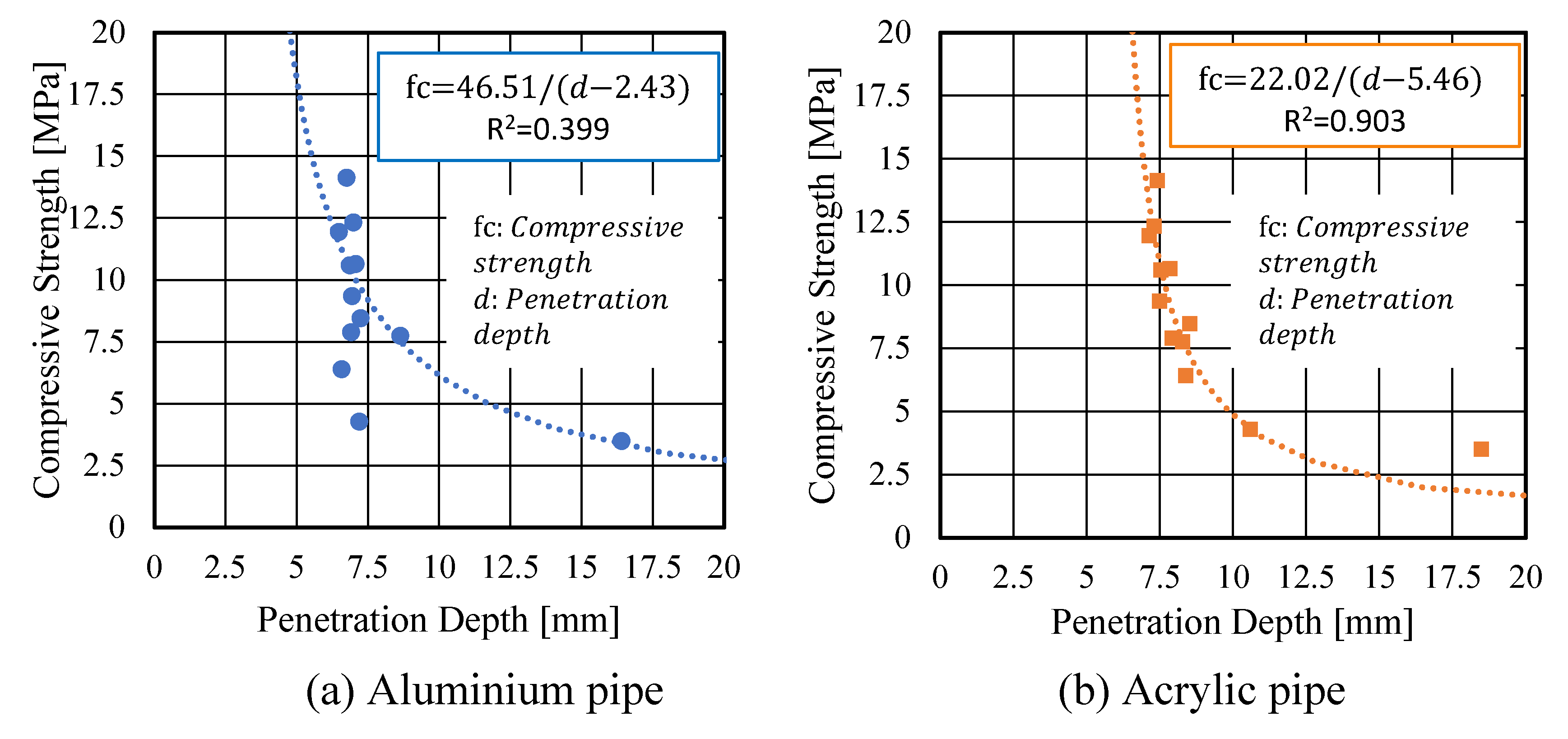
3.3. Relationship between Compressive Strength and Penetration Depth
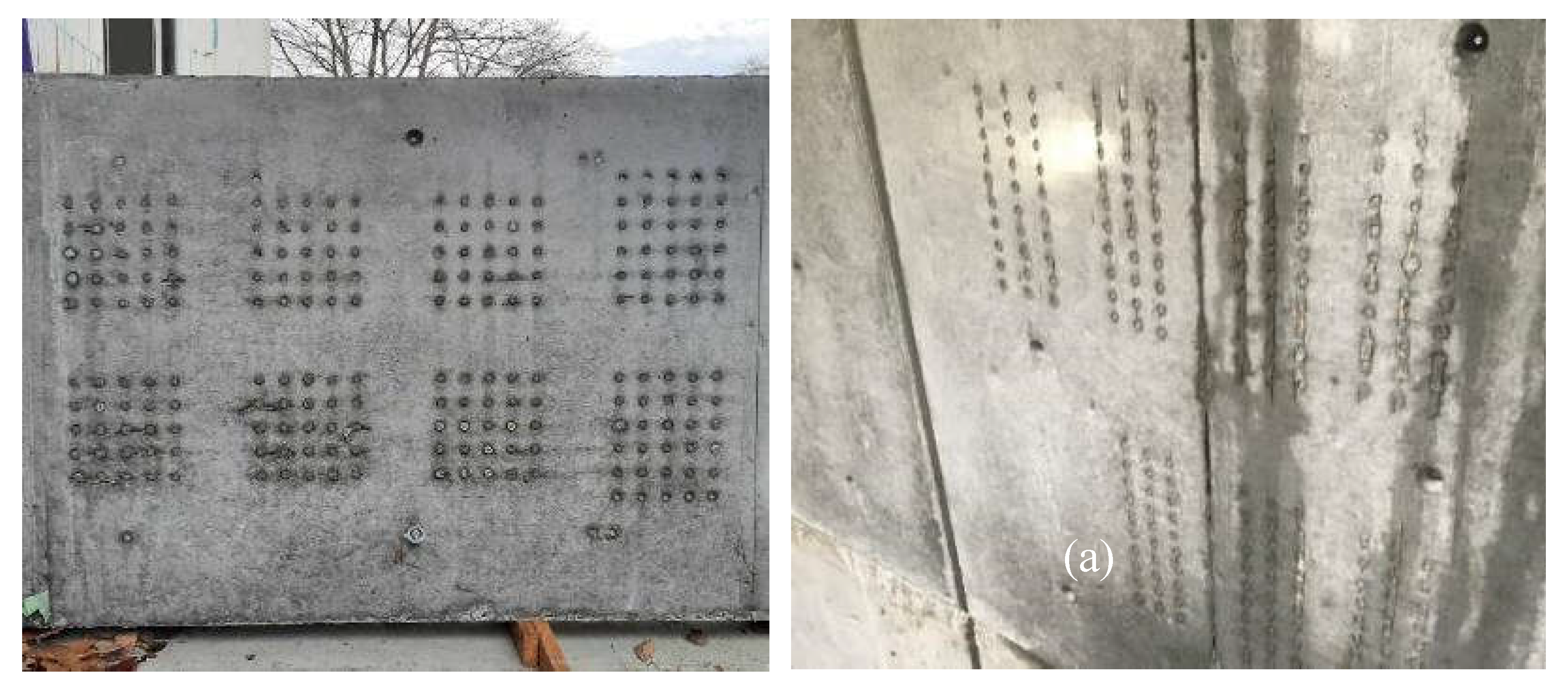
3.5. Surface Condition of Concrete after Demolding
4. Conclusions
- It is confirmed that the pin penetration test method is suitable to measure the early age compressive strength before demolding at actual construction site.
- The relationship between pin penetration depth and compressive strength of concrete was determined at actual construction site using the mock-up specimens. The obtained results were different from the existing curves obtained in laboratory experiments.
- The strength development of specimens was significantly delayed compared to mock-up specimens even when specimens were cured at same ambient air temperatures. Therefore, it confirms that the pin penetration test method is important to determine early-age compressive strength before demolding at actual construction site.
- The relationship between pin penetration depth and compressive strength gives higher correlation when using the acrylic pipes.
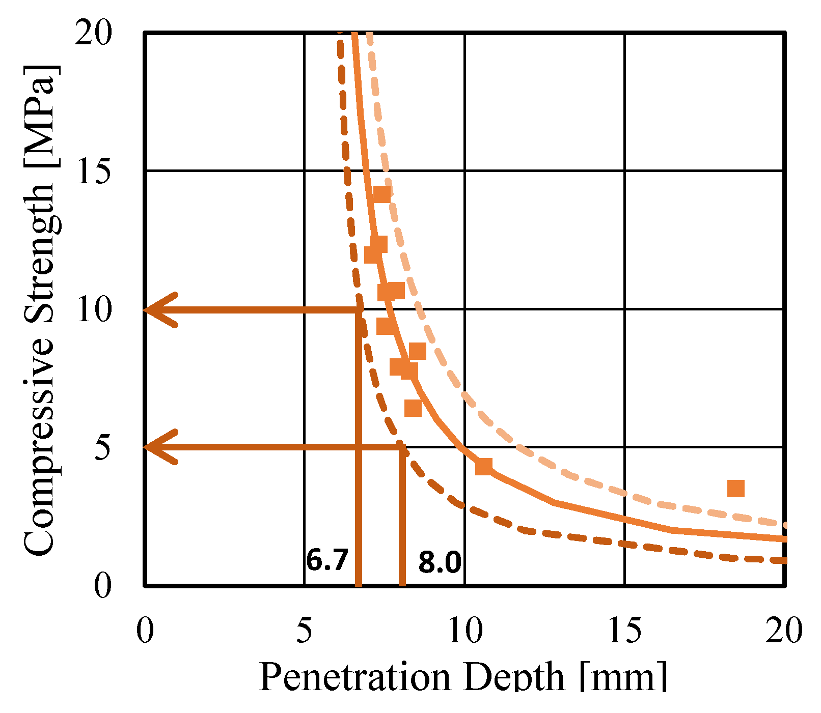
- It is confirmed that when the compressive strengths are greater than 5 MPa and 10MPa, the penetration depths are smaller than 8.0 mm and 6.7 mm, respectively.
Author Contributions
Funding
Data Availability Statement
Acknowledgments
Conflicts of Interest
References
- Narantogtokh, B.; Nishiwaki, T.; Pushpalal, D.; Taniguchi, M. Influence of pre-curing period at sub-zero temperature (-20 ℃) on the compressive strength of concrete. Cem. Sci. Concr. Technol. 2022, 76, 379–385. [Google Scholar] [CrossRef]
- Architectural Institute of Japan. Japanese Architectural Standard Specification JASS 5 Reinforced Concrete Work. Japan, <bold>2018.</bold> (In Japanese).
- Architectural Institute of Japan. Recommendation for Practice of Cold Weather Concreting. Japan, <bold>2010</bold> (in Japanese).
- Revilla-cuesta, V.; Ortega-lopez, V.; Faleschini, F.; Espinosa, A.B.; Serrano-lopez, R. Hammer rebound index as an overall-mechanical-quality indicator of self-compacting concrete containing recycled concrete aggregate. Constr. Build. Mater. 2022, 347, 128549. [Google Scholar] [CrossRef]
- Szilágyi, K.; Borosnyói, A.; Zsigovics, I. Extensive statistical analysis of the variability of concrete rebound hardness based on a large database of 60 years experience. Constr. Build. Mater. 2014, 53, 333–347. [Google Scholar] [CrossRef]
- Kumavat, N.R.; Chandak, N.R.; Patil, I.T. Factors influencing the performance of rebound hammer used for non-destructive testing of concrete members: A review. Case Stud. Constr. Mater. 2021, 14. [Google Scholar] [CrossRef]
- Odimegwu, T.C.; Amrul Kaish, A.B.M.; Zakaria, I.; Abood, M.M.; Jamil, M.; Ngozi, K.O. Nondestructive determination of strength of concrete incorporating industrial wastes as partial replacement for fine aggregate. Sensors. 2021, 21. [Google Scholar] [CrossRef] [PubMed]
- Mata, R.; Ruiz, R.O.; Nunez, E. Correlation between compressive strength of concrete and ultrasonic pulse velocity : A case of study and a new correlation method. Constr. Build. Mater. 2023, 369, 130569. [Google Scholar] [CrossRef]
- Bogas, J. A.; Gomes, M.G.; Gomes, A. Compressive strength evaluation of structural lightweight concrete by non-destructive ultrasonic pulse velocity method. Ultrasonics, 2013, 53, 962–972. [Google Scholar] [CrossRef] [PubMed]
- Andrade, M.; Lopes, A.; Júnior, M.; Cristina, G. Ultrasonic testing on evaluation of concrete residual compressive strength: A review. Constr. Build. Mater. 2023, 373, 130887. [Google Scholar] [CrossRef]
- Moreira, R.; Gondim, L.; Haach, V.G. Monitoring of ultrasonic velocity in concrete specimens during compressive loading-unloading cycles,” Constr. Build. Mater. 2021, 302, 124218. [Google Scholar] [CrossRef]
- Liang, M.T.; Wu, J. Theoretical elucidation on the empirical formulae for the ultrasonic testing method for concrete structures. Cem. Concr. Res. 2002, 32, 1763–1769. [Google Scholar] [CrossRef]
- Lencis, U.; Udris, A.; Korjakins, A. Frost influence on the ultrasonic pulse velocity in concrete at early phases of hydration process. Case Stud. Constr. Mater. 2021, 15, e00614. [Google Scholar] [CrossRef]
- Solis-Carcaňo, R.; Moreno, E. I. Evaluation of concrete made with crushed limestone aggregate based on ultrasonic pulse velocity. Constr. Build. Mater. 2008, 22, 1225–1231. [Google Scholar] [CrossRef]
- Ali-benyahia, K.; Kenai, S.; Ghrici, M.; Sbartaï, Z. Analysis of the accuracy of in-situ concrete characteristic compressive strength assessment in real structures using destructive and non-destructive testing methods. Constr. Build. Mater. 2023, 366, 130161. [Google Scholar] [CrossRef]
- Hobbs, B.; Kebir, M.T. Non-destructive testing techniques for the forensic engineering investigation of reinforced concrete buildings. Forensic. Sci. Intern. 2007, 167, 167–172. [Google Scholar] [CrossRef] [PubMed]
- Poorarbabi, A.; Ghasemi, M.; Moghaddam, M.A. Concrete compressive strength prediction using non-destructive tests through response surface methodology. Ain Shams Eng. J. 2020, 11, 939–949. [Google Scholar] [CrossRef]
- Yuasa, N. Research and practical application of non-destructive and micro-destructive testing of concrete structures. JTCCM Journal. 2013, 49, 2–8. (in Japanese). [Google Scholar] [CrossRef]
- Technical Committee on Concrete Strength Estimation, The Society of Materials Science Japan. Guideline for Compressive Strength Estimation of Concrete by Schmidt Hammer (Draft). Material Testing. 1958, 7, 426–430. (in Japanese). [Google Scholar] [CrossRef]
- Shiba, A.; Ishikawa, S.; Watanabe, S.; Kawakami, H. The Proposal and Evaluation of Concrete Strength Estimation by Rebound Hammer. Concr. J. 2005, 43, 35–40. (in Japanese). [Google Scholar] [CrossRef]
- Yuasa, N. Topic for Concrete Strength Presumption Using Rebound Hammer ─ Comparison between Rebound Numbers Using Various Hammers and Proposal of Requesting Method for Relationship between Rebound Numbers and Compressive Strength. Concr. J. 2010, 48, 23–30. (in Japanese). [Google Scholar] [CrossRef]
- Breysse, D. Nondestructive Evaluation of Concrete Strength: An Historical Review and a New Perspective by Combining NDT Methods. Const. Build. Mater. 2012, 33, 139–163. [Google Scholar] [CrossRef]
- Gunes, B.; Karatosun, S.; Gunes, O. Drilling resistance testing combined with SonReb methods for nondestructive estimation of concrete strength. Constr. Build. Mater. 2023, 362, 129700. [Google Scholar] [CrossRef]
- Al-sabah, S.; Sourav, S.N.A.; Mcnally, C. The post-installed screw pull-out test : Development of a method for assessing in-situ concrete compressive strength. J. Build. Eng. 2021, 33, 101658. [Google Scholar] [CrossRef]
- Maliha, M.; Nishiwaki, T.; Amin, A.F.M.S. A Screening Method for Very-Low-Strength Concrete. ACI Mater. J. 2022, 119. [Google Scholar] [CrossRef]
- Nguyen, M.H.; Nakarai, K.; Kubori, Y.; Nishio, S. Validation of simple nondestructive method for evaluation of cover concrete quality. Constr. Build. Mater. 2019, 201, 430–438. [Google Scholar] [CrossRef]
- Shinozaki, T.; Kemi, T.; Fujii, K.; Jitousono, H.; Shirayama, K. Assessment of Concrete Strength in Structure by Boss Specimen: Study on Soundness Evaluation of Reinforced Concrete Structures. AIJ Journal of Technology and Design. 2002, 8, 31–34. (in Japanese). [Google Scholar] [CrossRef]
- Shinozaki, T.; Fujii, K.; Jitosono, H.; Watanabe, K.; Kemi, T.; Shirayama, K. Assessment of Strength in Structure of High-Strength Concrete by Boss Specimen: Study on Soundness Evaluation of Reinforced Concrete Structures. AIJ Journal of Technology and Design. 2002, 8, 41–44. (in Japanese). [Google Scholar] [CrossRef]
- Shinozaki, T.; Sawamoto, T.; Morihama, K.; Hakamaya, H. A Study on Measurement of Early Age Concrete Strength with BOSS Specimen. Proceedings of the Japan Concrete Institute. 2015, 37, 1735–1740. (in Japanese). [Google Scholar]
- Miura, T.; Iwaki, I.; Itabashi, H. Study on Evaluating Deterioration of Concrete Structure Using Needle Penetration Test. Doboku Gakkai Ronbunshu. 1999, 43, 245–255. (in Japanese). [Google Scholar] [CrossRef]
- Miyabe, K.; Tanigawa, Y.; Mori, H.; Kurokawa, Y. Estimation of Mortar Strength by Windsor-Pin Method. Proceedings of the Japan Concrete Institute. 2004, 26, 1833–1838. (in Japanese). [Google Scholar]
- Maliha, M.; Nishiwaki, T.; Fujiwara, T.; Minemura, T. In-Place Test Method with Penetration Resistance for Low-Strength Concrete. Proceedings of the Japan Concrete Institute, 1732. [Google Scholar]
- Iwaki, K.; Hirama, A.; Mitani, K.; Kaise, S.; Nakagawa, K. A Proposal of Control Method on Shotcrete Strength by Pin Penetration Test Using Air Pressure. Doboku Gakkai Ronbunshu. 2000, 46, 99–112. (in Japanese). [Google Scholar] [CrossRef]
- Noguchi, T. Quality Control System in Curing Concrete Using Small Integrated Circuit for Monitoring Temperature and Attitude on Formworks. JACIC Research and Development Report 2010, 2010. (in Japanese). [Google Scholar]
- Nishiwaki, T.; Takasugi, F.; Narantogtokh, B.; Hara, S.; Maliha, M. A method to estimate the early age compressive strength of concrete before demolding using a pin penetration device. J. Struct. Constr. Eng. 2022, 88, 18–26. (in Japanese). [Google Scholar] [CrossRef]
- Popovics, S. Strength and Related Properties of Concrete: A Quantitative Approach; John Wiley & Sons: Hoboken, NJ, USA, 1998; p. 12. [Google Scholar]
- Zhou, S.; Sun, Q.; Wu, X. Impact of D/t Ratio on Circular Concrete-Filled High-Strength Steel Tubular Stub Columns under Axial Compression. Thin-Walled Struct. 2018, 132, 461–474. [Google Scholar] [CrossRef]
- Chen, H.; Wu, L.; Jiang, H.; Liu, Y. Seismic Performance of Prefabricated Middle Frame Composed of Special-Shaped Columns with Built-in Lattice Concrete-Filled Circular Steel Pipes. Structures 2021, 34, 1443–1457. [Google Scholar] [CrossRef]
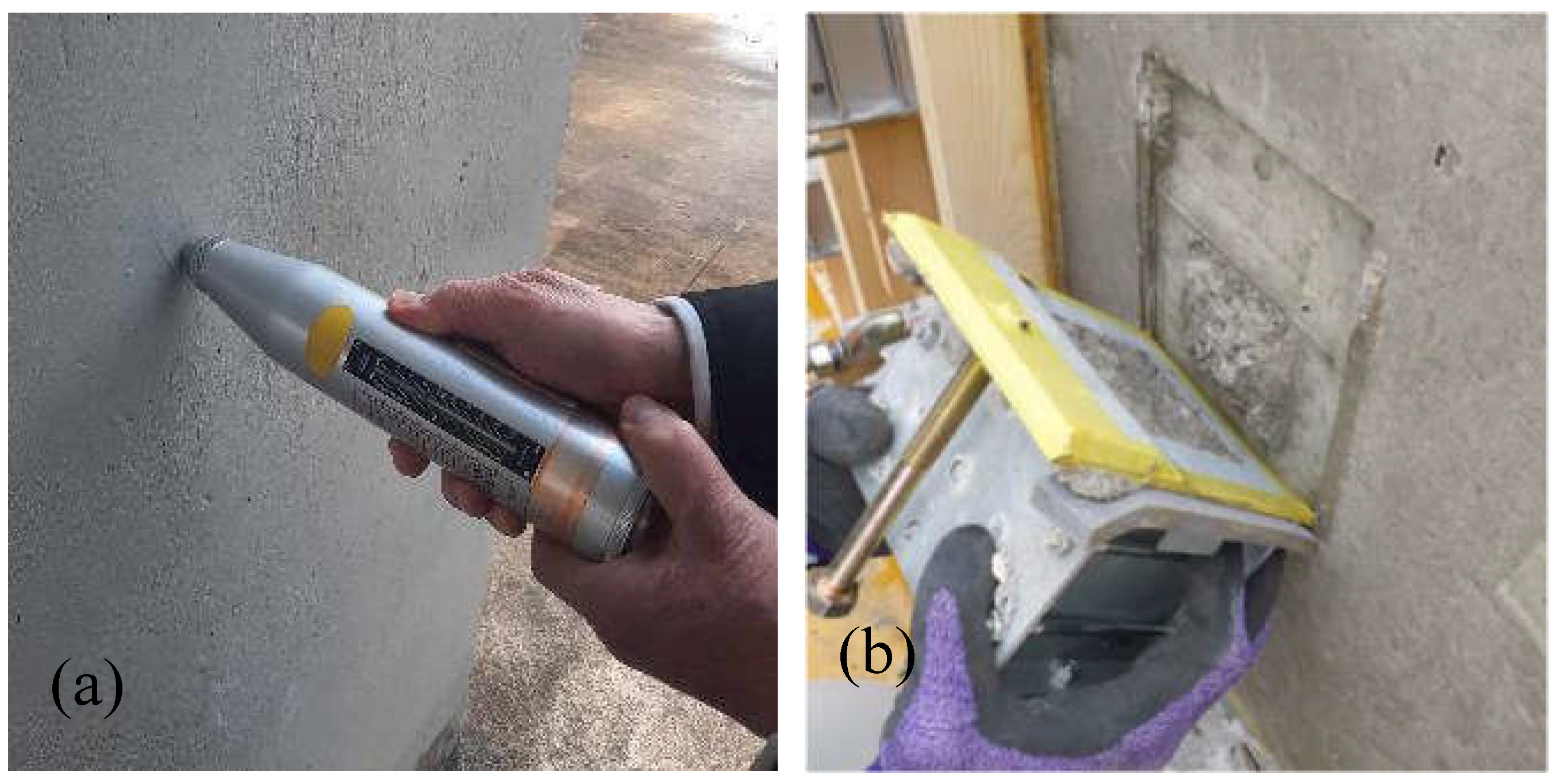
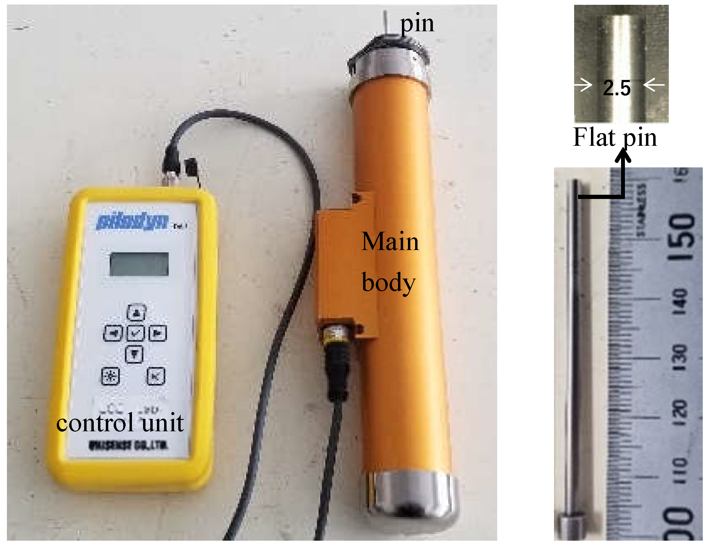
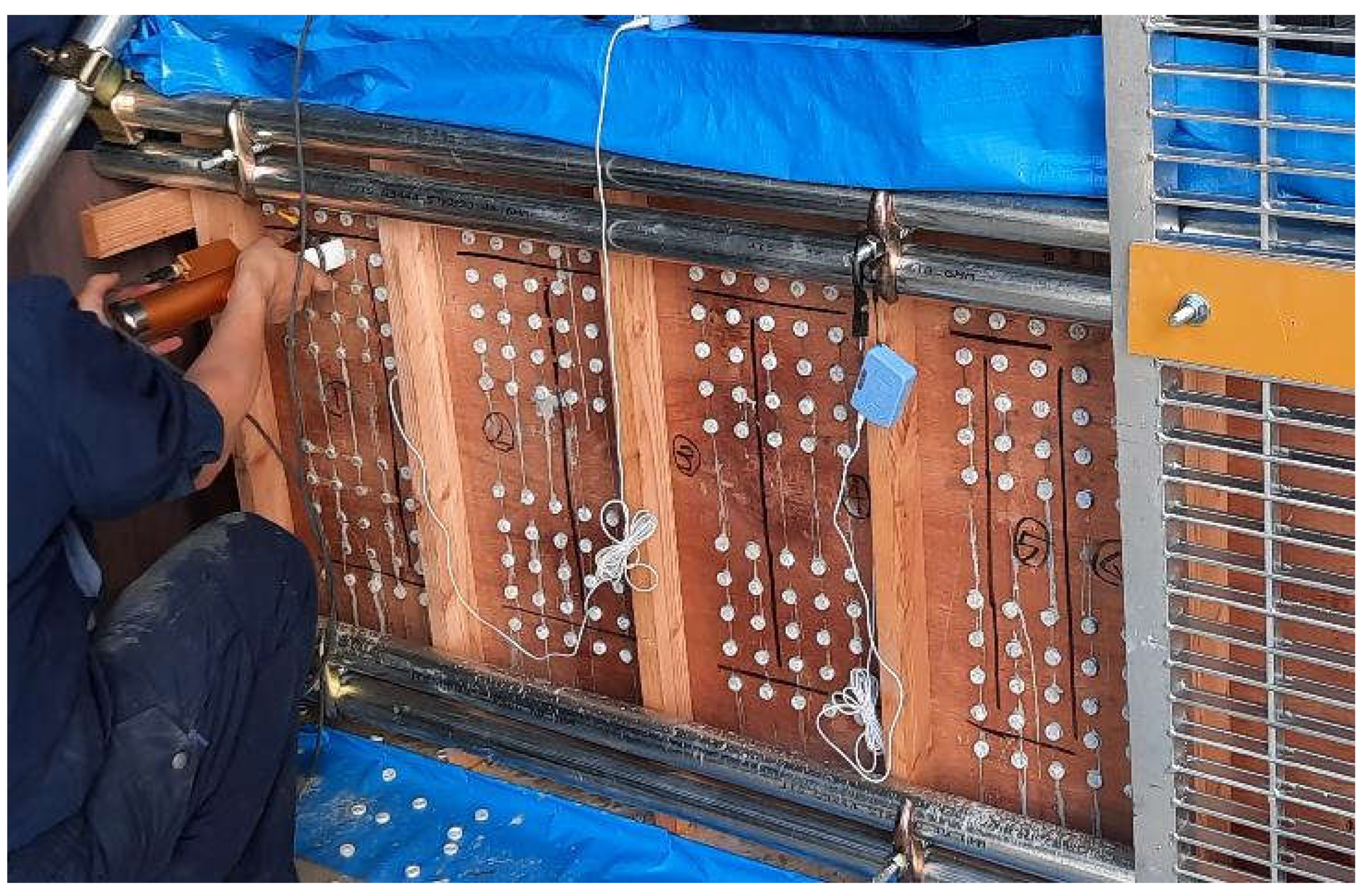
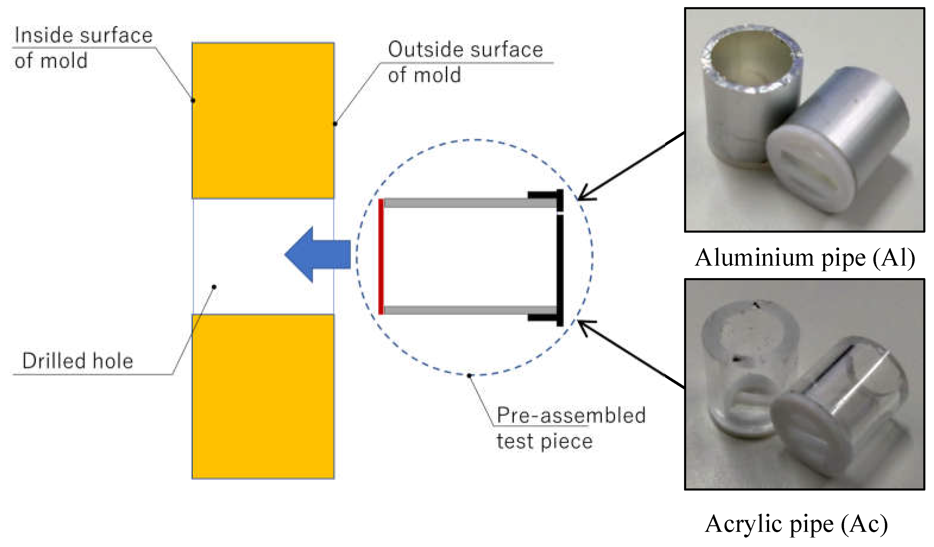
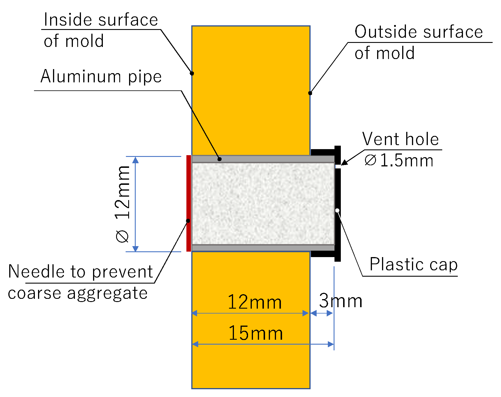
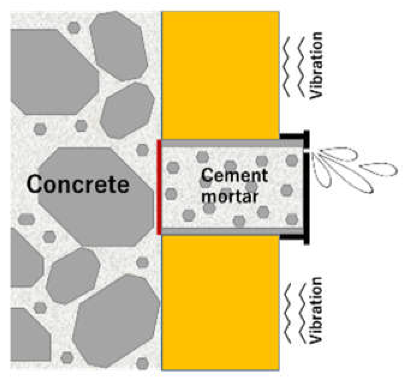
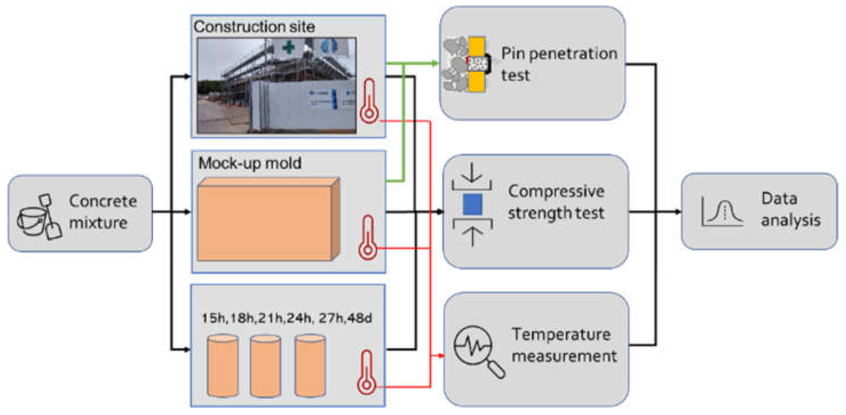
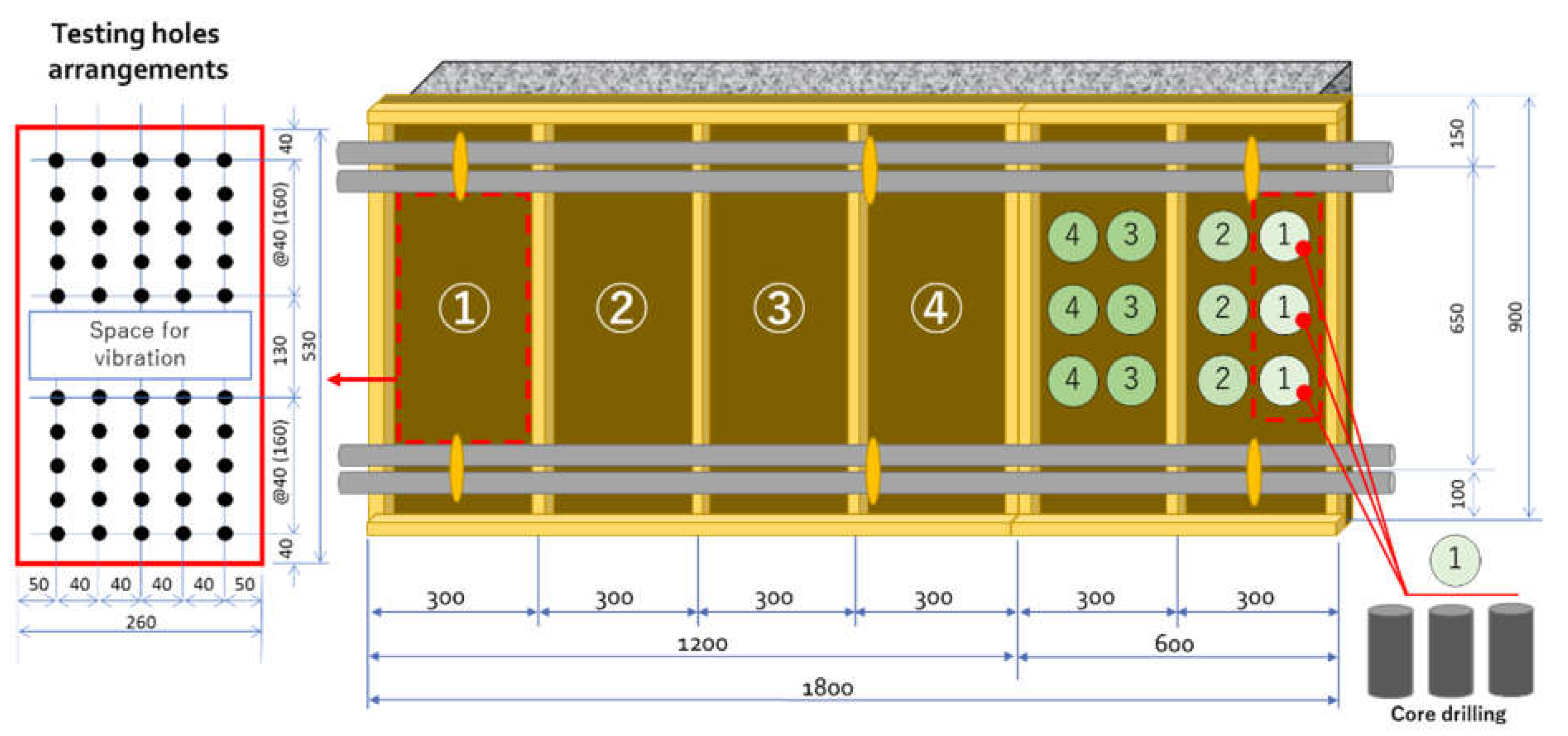
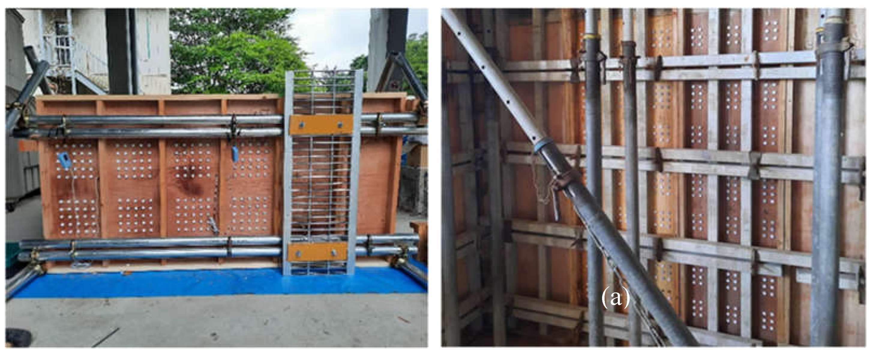
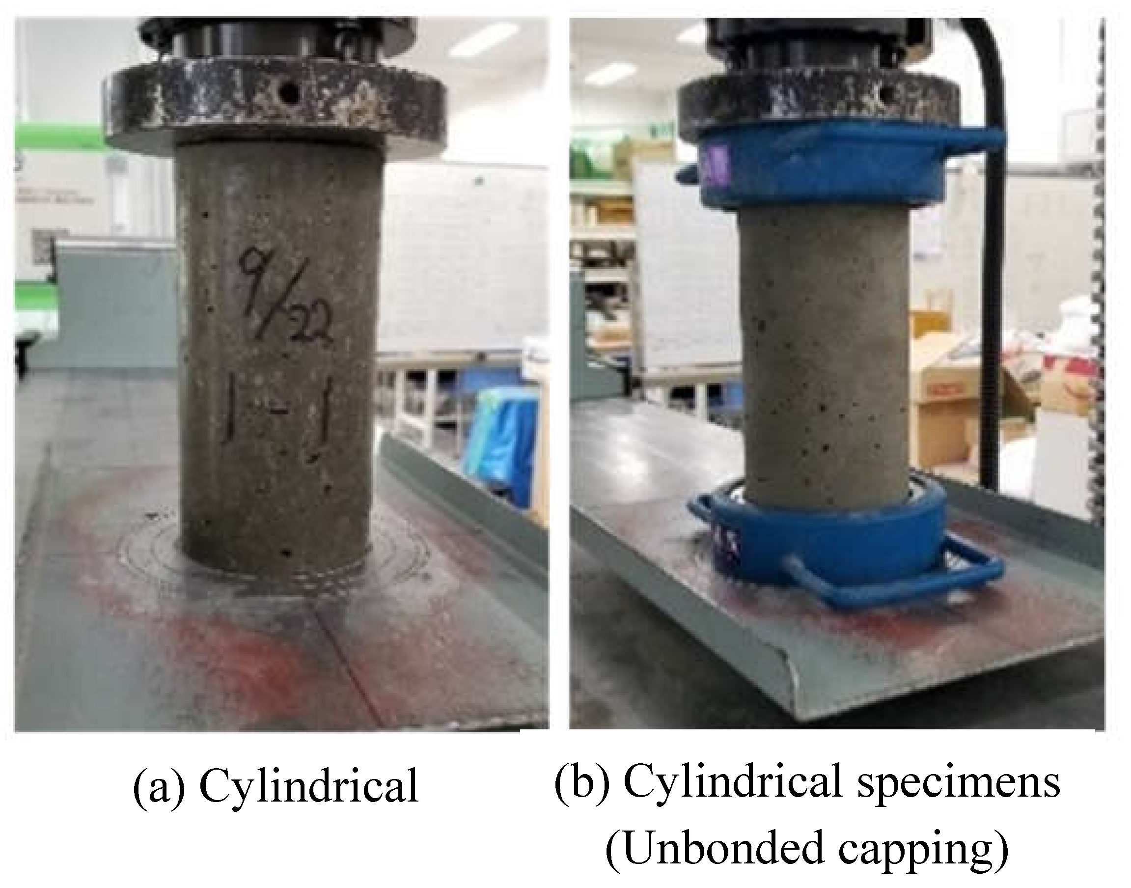
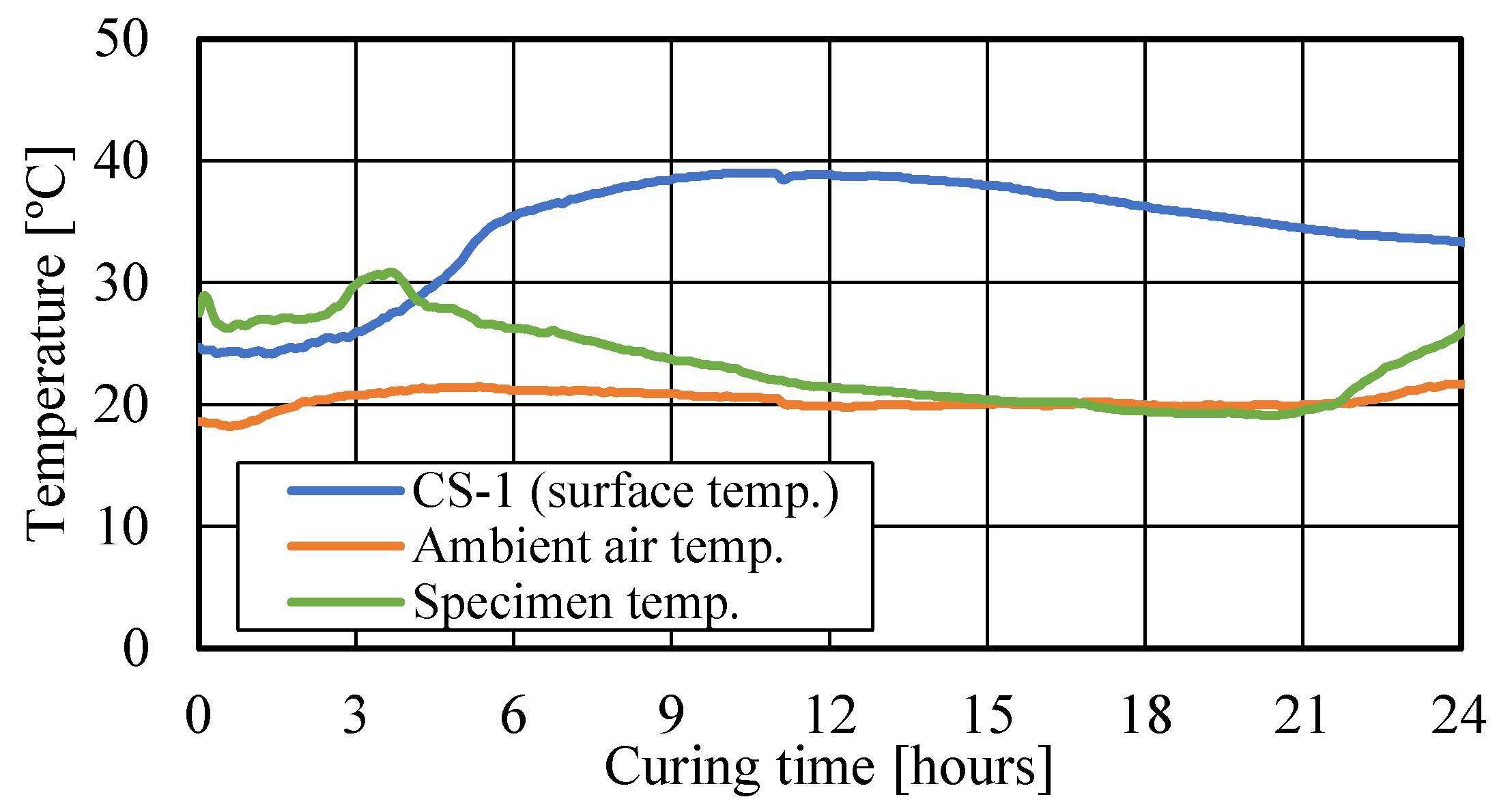
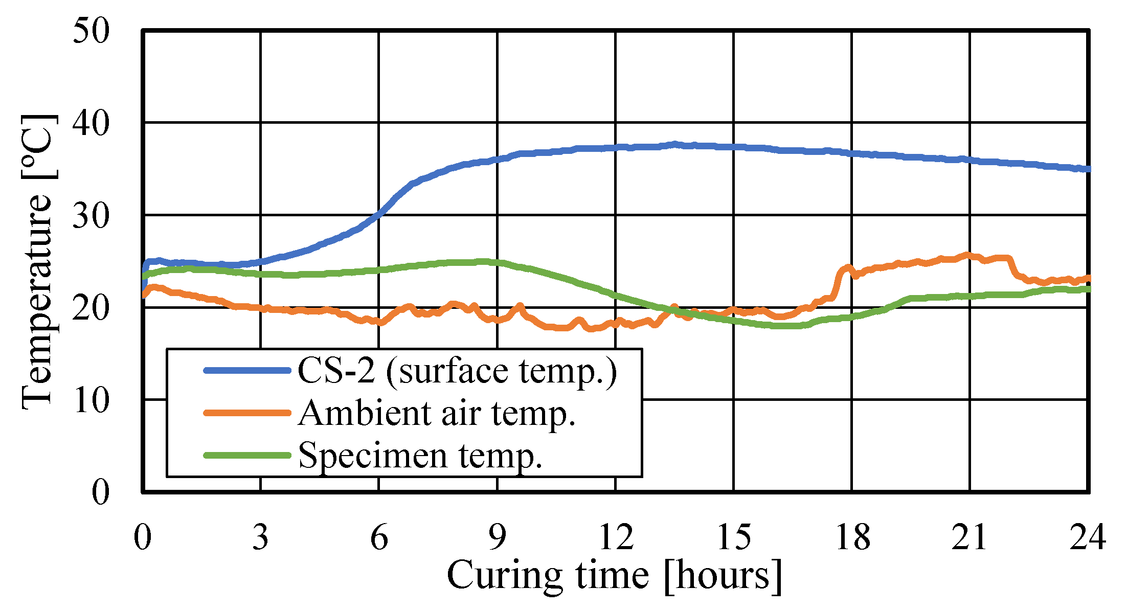
| Measuring range | 0 ~ 35 mm |
| Measurement accuracy | 0.1 mm |
| Dimensions of device | 50 × 70 × 335 mm |
| Weight | ~2 kg |
| Energy | 6 J(Nm) |
| Determination | Curing time | ||||||
| 15h | 18h | 21h | 24h | 27h | 48h | ||
| Specimens at construction site and mock-up mold | |||||||
| Mock-up mold | Al pipe | ○ | ○ | ○ | ○ | ○ | ○ |
| Ac pipe | ○ | ○ | ○ | ○ | ○ | ○ | |
| Construction site | Al pipe | ○ | ○ | ○ | ○ | ||
| Ac pipe | ○ | ○ | ○ | ○ | |||
| Series | Testing condition | Nominal Strength [MPa] |
Slump [cm] |
|
| CS-1 | Construction site (at ambient air temperature) |
36 | 21 | |
| CS-2 | 36 | 21 | ||
| MS-1 | Mock-up specimens (at ambient air temperature) |
24 | 18 | |
| MS-2 | 30 | 18 |
| Series | W/C [%] |
Cement | Water | Fine aggregate* | Coarse aggregate | Admixture |
| CS-1 | 41.0 | 427 | 175 | 598, 158 | 969 | 6.41 |
| CS-2 | 41.0 | 427 | 175 | 598, 158 | 969 | 6.41 |
| MS-1 | 54.0 | 324 | 175 | 659, 165 | 990 | 3.24 |
| MS-2 | 46.5 | 376 | 175 | 626, 157 | 990 | 3.76 |
| Compressive strength [MPa] |
Penetration depth [mm] (Acrylic pipe) |
| 5.0 | 8.02(8.0) |
| 10.0 | 6.74 (6.7) |
Disclaimer/Publisher’s Note: The statements, opinions and data contained in all publications are solely those of the individual author(s) and contributor(s) and not of MDPI and/or the editor(s). MDPI and/or the editor(s) disclaim responsibility for any injury to people or property resulting from any ideas, methods, instructions or products referred to in the content. |
© 2024 by the authors. Licensee MDPI, Basel, Switzerland. This article is an open access article distributed under the terms and conditions of the Creative Commons Attribution (CC BY) license (http://creativecommons.org/licenses/by/4.0/).


