1. Introduction
Joint wear simulators have been developed to provide insight into the wear performance of total joint replacements and preclinically evaluate implant designs and bearing materials
[1,2,3,4,5,6]. Longer implantation periods and younger, heavier and more active patients contribute to increased tribological demand on artificial joints
[7,8]. Historically, the primary cause of most hip replacements’ failure is wear
[9,10,11,12,13]. Patient-specific factors like age, gender, weight, activity level, and individual kinematic patterns have been found to influence wear
[14,15,16]. To ensure the tribological performance of joint arthroplasties, they undergo standard testing procedures before being introduced to the market. However, current regulatory preclinical testing standards, such as ISO 14242-1 and ISO 18192-1
[17,18], utilize simplified and stylized waveforms to define standardized loading conditions. These conditions do not accurately represent the loads and motion experienced by different patient groups in real-life activities
[19,20].
The use of mechanical simulators is considered the pre-eminent method for realistically predicting performance of biomaterials combinations and implant geometry will behave tribologically after total joint replacement
[21,22]. Compared to the more simplistic pin-on-disc machines, simulators aim to replicate the actual tribological conditions experienced by the joint, which is derived from a more sophisticated design and electro-mechanical control
[23,24]. The objective of wear simulation is to determine the wear performance of the implant or bearing combination and analyse its dependence on multiple factors, including load, kinematics, temperature, and the orientation of the sliding components within the implant
[25,26]. However, another aspect that is lacking in the existing literature is the advancement in the control system of the simulator and testing clinically relevant waveforms pertaining to patients’ real-life activities
[27,28]. To ensure that these simulators accurately reflect real-world situations, it is crucial to simulate more challenging scenarios and incorporate a wider range of daily activities, particularly for younger and more active patients
[29]. Existing literature on joint simulators predominantly highlights advancements in control system development for in-vitro biomechanical testing of the spine, with relatively less emphasis on in-vitro wear testing. The purpose of in-vitro biomechanical testing is to examine the three-dimensional motion of the spine in response to loads. This is normally conducted on a cadaver spine by using either multiple spinal segments or a single functional spinal unit (FSU)
[30,31,32,33,34,35,36,37].
There is a noticeable gap in the current literature concerning the pre-clinical evaluation of prostheses via in-vitro wear testing on joint simulators, specifically regarding the incorporation of daily-living (DL) motion and load cycles for the spine, knee, and hip. These DL profiles typically stem from gait lab investigations involving a significant patient cohort participating in activities like walking, sitting, standing, stair ascent, and descent
[26,38]. One factor contributing to this gap is the constraints early joint simulators faced due to limited degrees of freedom in motion and load. However, modern joint simulators, particularly the electro-mechanical ones discussed in
[39] for the knee and hip joints from the University of Leeds, in addition to the one utilized in this study for the spine, are programmable and demonstrate improved adaptability in handling complex motion and loading parameters. Another reason for the absence of testing DL profiles is the limited requirement in pre-clinical testing of joint prostheses to adhere solely to ISO standards, which encompass simplified gait cycles rather than the diverse real-life scenarios encountered by individuals
[28]. The main rationale for integrating DL profiles into the testing protocol is that studies conducted by
[40,41] reveal that the wear patterns observed on retrieved implants cannot be reproduced using existing standards.
Therefore, this study addresses this gap by introducing a novel control algorithm tailored for the Leeds spinal wear simulator. The algorithm's effectiveness is evaluated by subjecting both ISO and DL profiles to the tolerances outlined in ISO 18192-1 for the cervical spine
[17]. The paper focuses on developing and proof-of-concept trials of an advanced control system for a joint simulator used in tribological testing of spinal prostheses. Two control algorithms, namely Proportional-Integral (PI) and Fuzzy-PI, were developed and tested. Utilizing the novel HiL environment
[42] offered a robust platform to test both controllers rigorously across various ISO-compliant and daily-living profiles of the spine, hip and knee. The Leeds spine simulator was utilised as a testing platform to validate both fuzzy-PI and PI control algorithms based on its robustness and flexibility to test simple sinusoid profiles of the spine that are ISO compliant
[17] as well as profiles representing activities of daily living (ADLs).
This paper aims to evaluate and compare the effectiveness of the conventional PI controller with the enhanced Fuzzy-PI controller within the context of a joint simulator. The objective is to confirm the performance of these controllers by aligning their outcomes with the tolerances outlined in the ISO-18192-1 standards for the cervical spine.
2. Materials and Methods
In this paper, a novel intelligent controller employing a fuzzy-PI algorithm was applied to the Leeds SimSol spine simulator (Simulator Solutions Ltd, UK). The primary purpose was to assess its effectiveness in conducting wear tests on tribological implants. The fuzzy-PI control system underwent an initial phase of development and thorough testing using a universal Hardware-in-the-Loop (HiL) setup
[42]. This HiL environment was specifically designed to evaluate potential control algorithms prior to integrating them into the operational framework of the Leeds spine
[42,43]. Before testing Fuzzy-PI and PI controllers on the spine wear simulator, the preceding developmental milestones were achieved:
2.1. Spine Wear Simulator
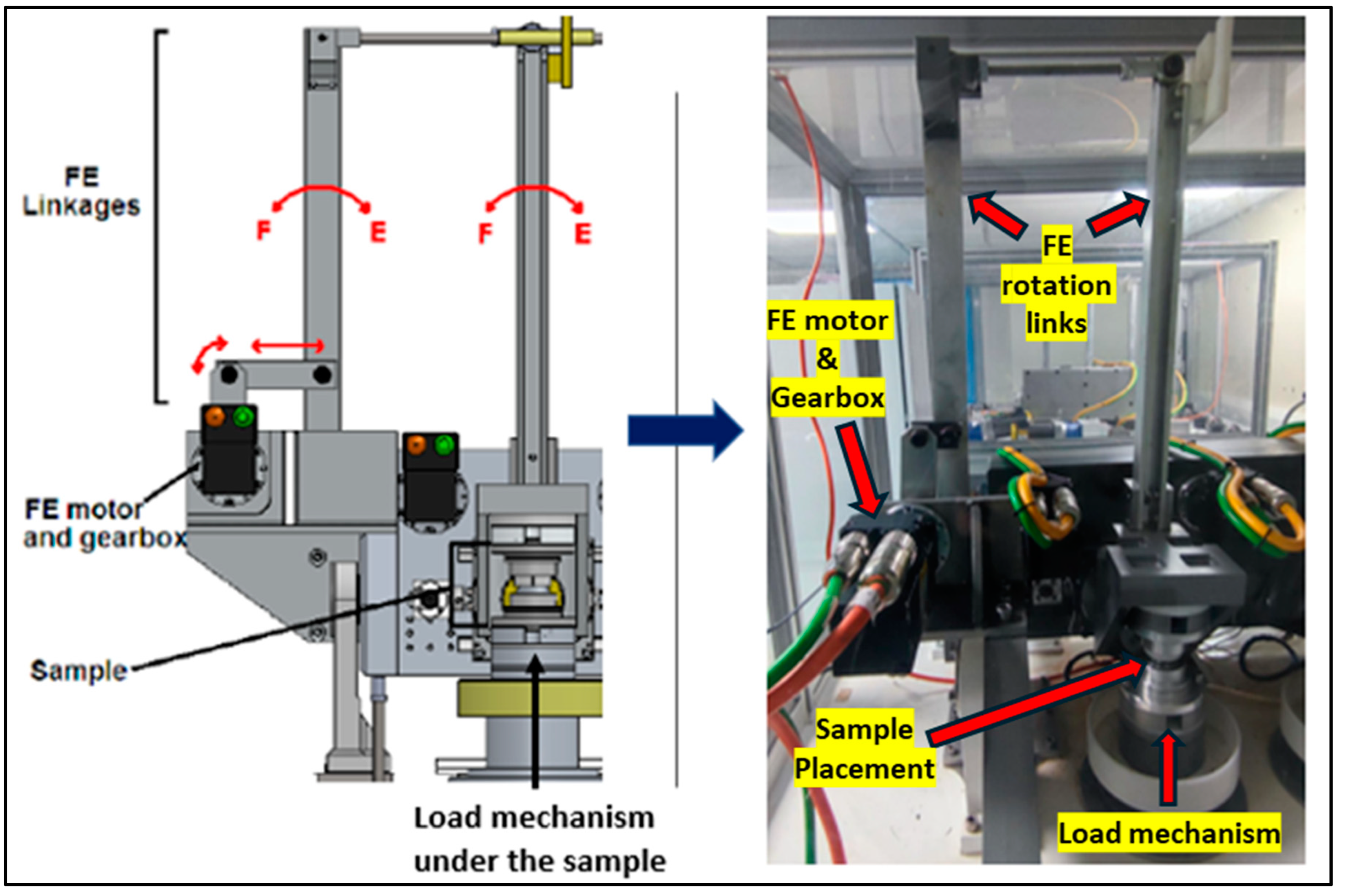
Figure 1 below is a segment of the spinal wear simulator situated at the University of Leeds. This apparatus employs electro-mechanical actuators to regulate both kinetic and kinematic inputs. Precise motion control is facilitated by harmonic-drive motors, which have been previously demonstrated the required performance in this context. The simulator is capable of achieving six degrees of freedom, with five degrees effectively operational.
Two velocity-based control algorithms, Proportional-Integral (PI) and Fuzzy-PI, were developed and tested. The innovative HiL environment provided a robust platform to rigorously develop and test both controllers across ISO-compliant and daily-living profiles for the spine, hip, and knee
[42]. The Leeds spine simulator validated both fuzzy-PI and PI control algorithms, demonstrating its robustness and flexibility to test simple sinusoidal profiles from ISO-18192-1 for the spine and profiles representing activities of daily living (ADLs). The test profiles were selected based on their waveform configuration, frequency component bandwidth, and relevance to human ADLs.
During control prototyping on the HiL system
[42,43], the PI controller struggled to overcome phase lag at higher frequencies (e.g., 2 Hz) as specified in ISO 18192-1 standards, requiring constant manual gain adjustments. To address these issues, the FuzzyPI controller was developed.
This paper introduces an innovative intelligent control algorithm that combines fuzzy logic (FL) with a proportional-integral (PI) controller, specifically designed for tribological testing on joint simulators. The derivative (D) term was excluded due to its sensitivity to external disturbances, which caused instability with its aggressive response.
The proposed Fuzzy-PI controller seeks to synergistically complement the simplicity and robustness of PI, whereby the Fuzzy Logic (FL) controller acts as a supervisor to the PI controller and optimally selects gains at in real-time as the test unfolds.
The non-linear characteristics of a fuzzy controller make it more effective in capturing and representing complex behaviours compared to a classical linear PID controller
[44]. The Fuzzy-PI controller has a range of pre-determined K
p and K
i gains implemented in real-time that vary according to the changing shape and frequency of the demand profile.
Figure 2 provides a schematic to describe the advanced Fuzzy-PI control methodology developed.
The two controllers were comparatively tested against a selection of profiles. Each test ran 100 cycles. However, some hip ADL profiles such as climbing staircase up and down, stumbling and tibial internal-external rotation of knee ran only for 20-40 cycles because of its extreme complexity in shape and the frequency components within. These profiles were tested trialed just to test the robustness of both PI and Fuzzy-PI controllers and the capability of the spine simulator to simulate profiles of other joints like hip and knee.
The profile frequency was adjusted across four values: 0.5Hz, 1Hz, 1.5Hz, and 2Hz, with 2Hz being the maximum allowable test frequency according to ISO standards. The controller's performance was assessed using metrics outlined in ISO 18192-1 (accuracy of ±0.5° at the maxima and minima of the motion and ±2% of the full cycle time for phasing)
[17].
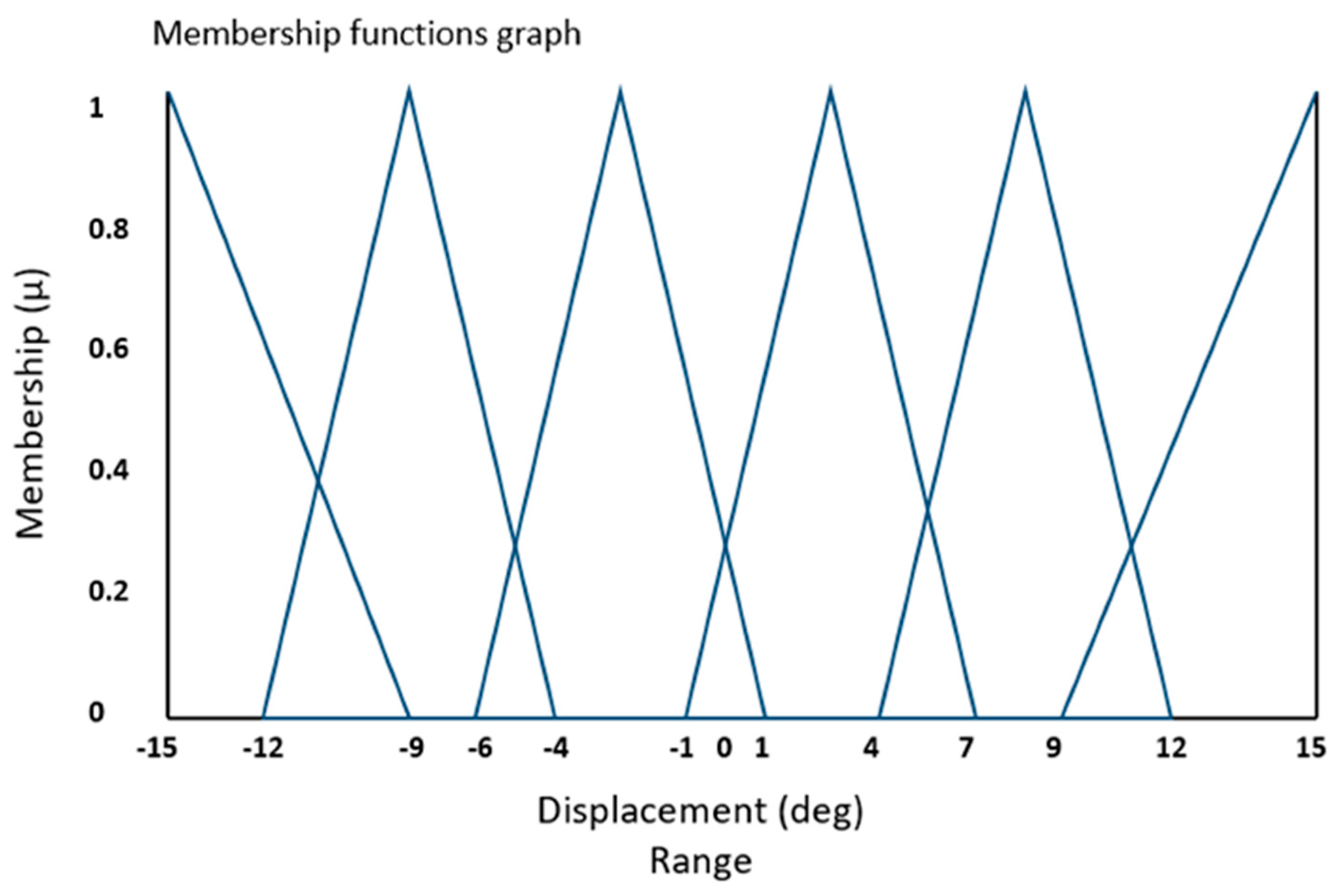
Figure 3 displays a fuzzy triangular membership function, where the horizontal X-axis represents the universe of discourse. This universe of discourse encompasses the numerical range of fuzzy values established by the system designer, aligning with the controller's specifications and requirements. Specifically, the X-axis is carefully selected to cover the minimum and maximum values of all the profiles tested in this study.
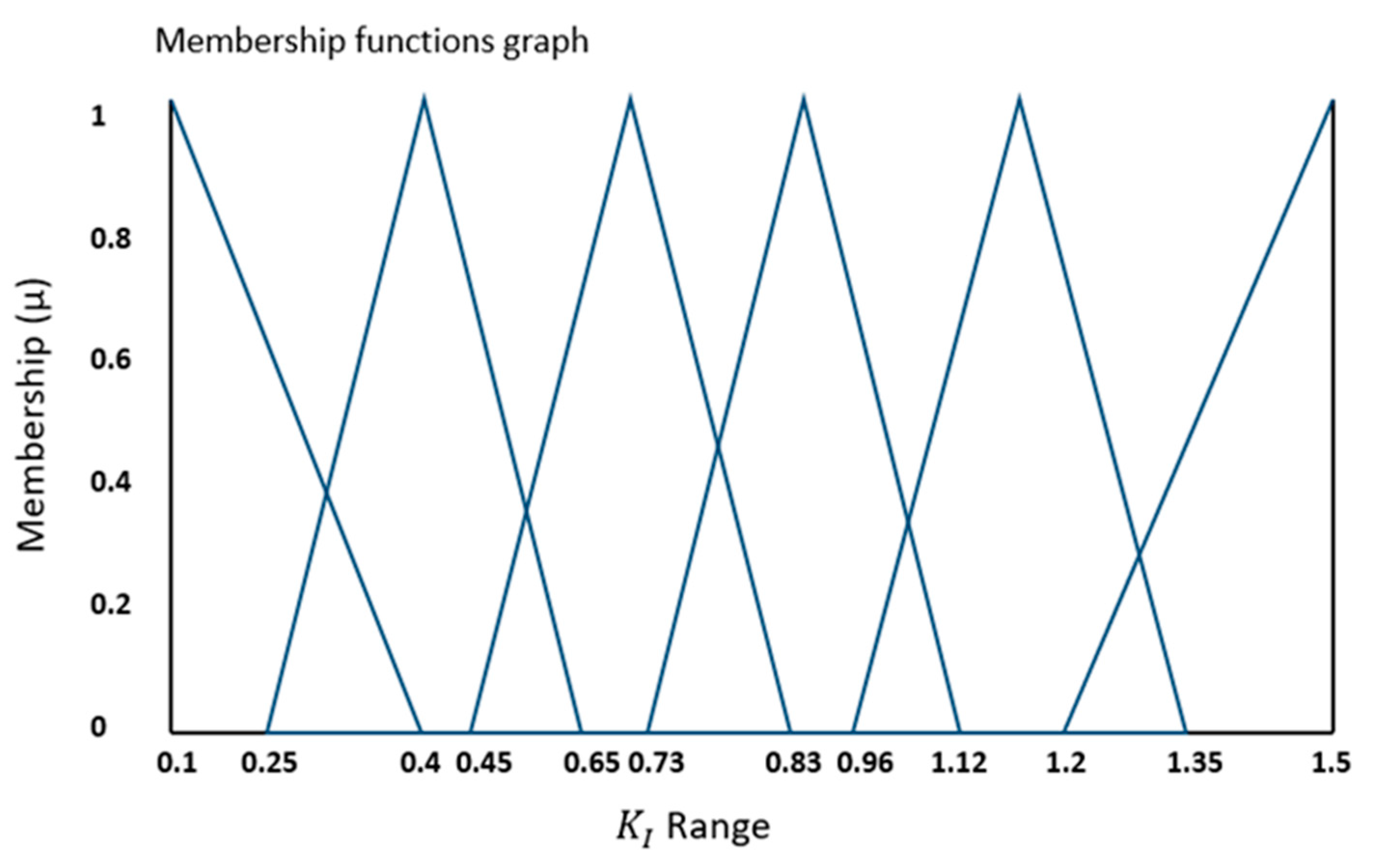
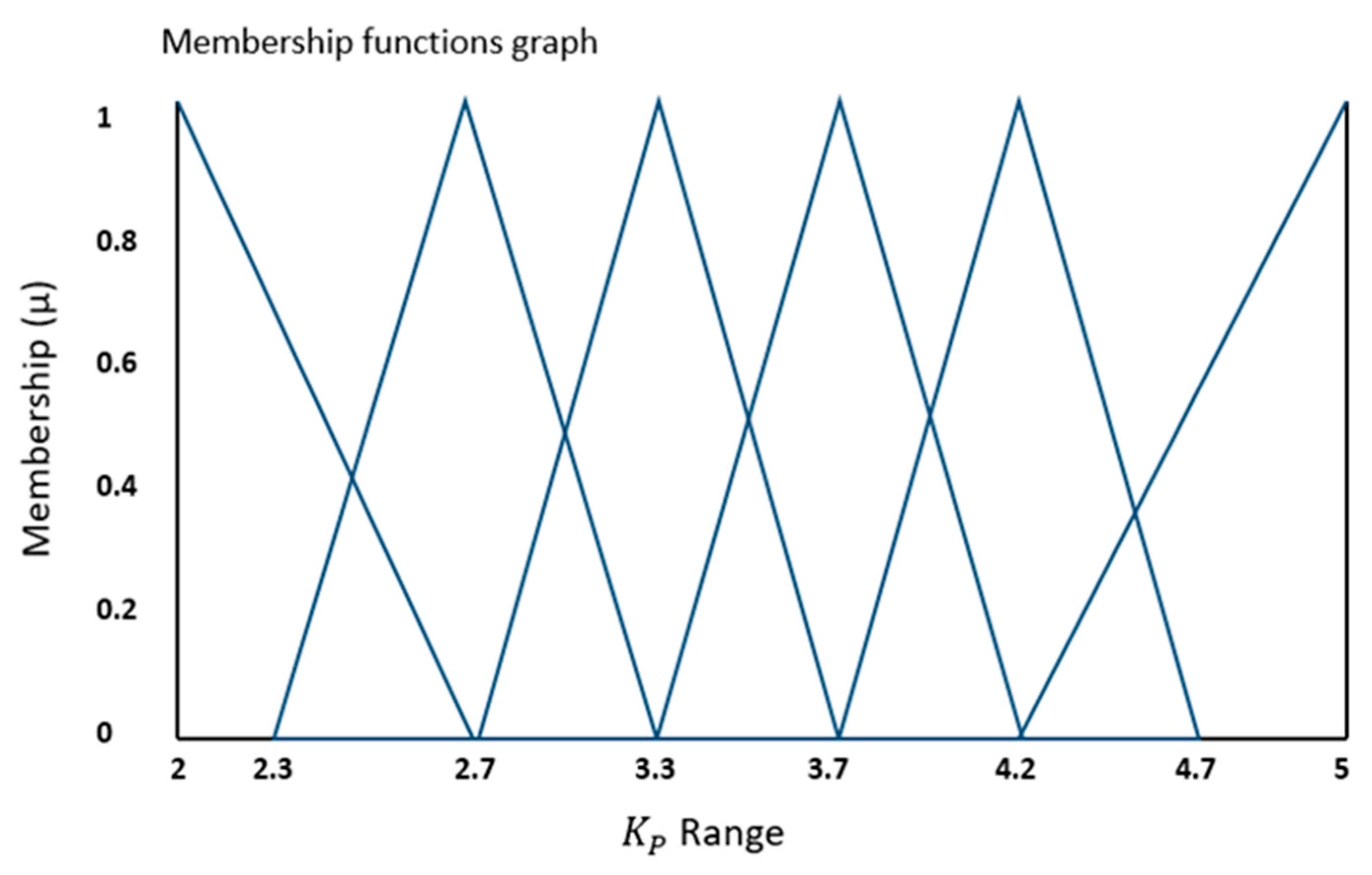
Additionally depict the complete range of proportional (
) and integral (
) gains for the error values falling within the range outlined in
Figure 2.3. In these figures, the vertical Y-axis represents the degree of membership (µ), which takes values within the range of {0, 1}.
Figure 3.
Input fuzzy membership function for displacement error (e).
Figure 3.
Input fuzzy membership function for displacement error (e).
Figure 4.
Output fuzzy membership function for gain.
Figure 4.
Output fuzzy membership function for gain.
Figure 5.
Output fuzzy membership function for gain.
Figure 5.
Output fuzzy membership function for gain.
Table 1.
Fuzzy rules to evaluate Displacement error (e) Kp, Ki using linguistic form.
Table 1.
Fuzzy rules to evaluate Displacement error (e) Kp, Ki using linguistic form.
| Sr no. |
Fuzzy Rules |
| 1 |
IF Displacement Error is "Large Neg" THEN Kp is "Extreme" ALSO Ki is "Extreme" |
| 2 |
IF Displacement Error is "Medium Neg" THEN Kp is "Very Large" ALSO Ki is "Very Large" |
| 3 |
IF Displacement Error is "Small Neg" THEN Kp is "Large" ALSO Ki is "Large" |
| 4 |
IF Displacement Error is "Small Pos" THEN Kp is "Medium" ALSO Ki is "Medium" |
| 5 |
IF Displacement Error is "Medium Pos" THEN Kp is "Small" ALSO Ki is "Small" |
| 6 |
IF Displacement Error is "Large Pos" THEN Kp is "Small" ALSO Ki is "Very Small" |
3. Results
The HiL simulation described in Iyer et al.
[43] provided a robust and reliable platform for the rapid development and testing of PI and Fuzzy-PI controllers. This setup allowed for the verification and fine-tuning of the controllers, particularly through the iterative creation and adjustment of optimal fuzzy membership functions, all within a low-risk environment before their potential deployment to the spinal joint simulator for displacement control testing.
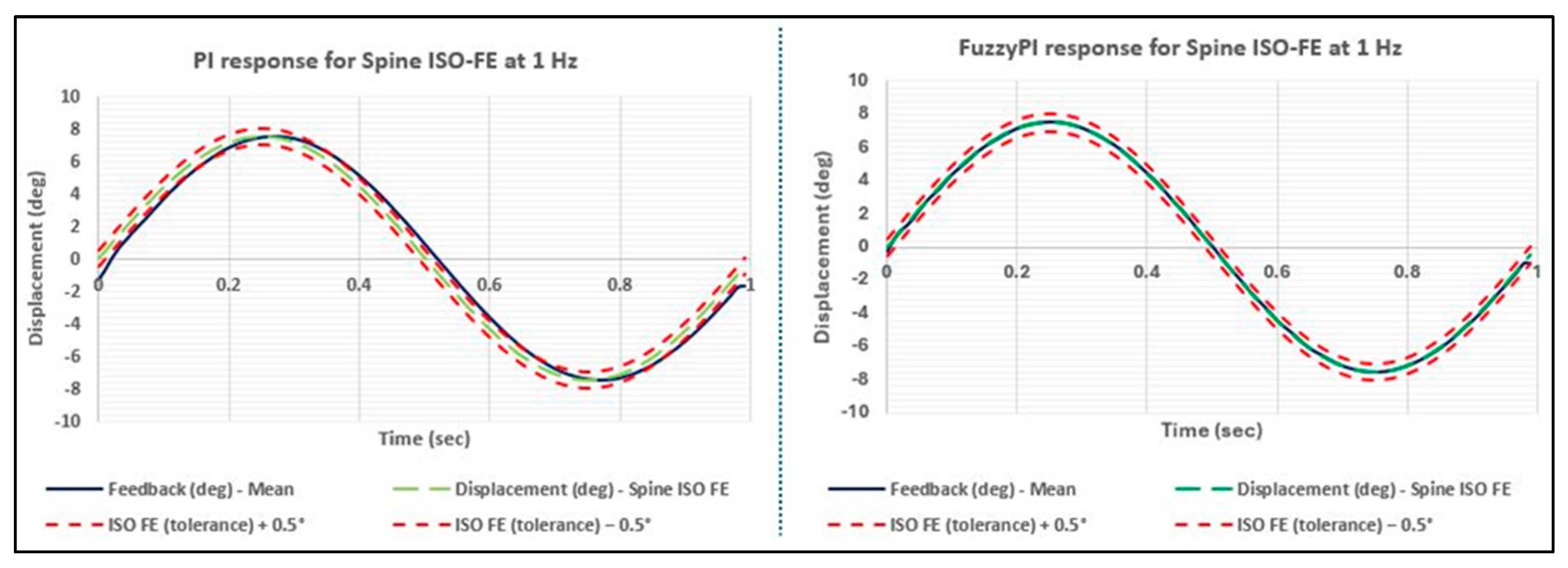
To validate the real-time performance of both PI and Fuzzy-PI controllers on the Leeds spinal wear simulator, an initial assessment was conducted utilizing a standardized flexion-extension (FE) profile delineated in ISO 18192-1
[17]. Subsequently, a walking profile of the hip obtained from the gait lab measurements
[20] at Leeds Teaching Hospital Trust underwent testing, owing to its intricate shape, frequency components, and direct relevance to human activities of daily living (ADL). The findings presented illustrate the mean response observed over 100 simulated cycles at frequencies of 1 Hz and 2 Hz.
Figure 6 exhibits the control responses of both controllers against the target FE displacement profile prescribed in ISO 18192-1. As illustrated in
Table 2 the Fuzzy-PI controller demonstrated superior performance over the industry standard PI controller in terms of phase lag as per the tolerances stipulated in the ISO 18192-1 standards. Nevertheless, the PI controller adhered to the ISO tolerance limit for both amplitude and phase, proving its efficacy despite being outperformed by the Fuzzy-PI controller in terms of phase lag.
The performance difference in phase between the two controllers can be attributed to the tuning process of the PI controller on the Leeds spine simulator. Specifically, the PI controller was fine-tuned for the 1 Hz profile, with parameters set to Kp = 3.5 and Ki = 0.73, through iterative testing across a range of profiles, including the daily-living hip profile. In contrast, the Fuzzy-PI controller, instead of being fixated to a singular value, followed a range of K
p and K
i gains as depicted in
Figure 4 and
Figure 5 as Fuzzy Triangular membership functions.
Figure 7 indicates the auto-tuning of fuzzy gains ion real-time to best match the demand ISO FE profile.
Figure 8 illustrates the responses of the controllers to the spine ISO FE profile at a frequency of 2 Hz. Consistently, as indicated in
Table 2 for the 2 Hz scenario, the Fuzzy-PI controller exhibited superior performance over the PI controller in terms of phase lag, maintaining closer proximity to the ISO tolerance limits compared to the PI controller, which exceeded the tolerance by 1.6% as compared to 0.2% for Fuzzy-PI. Moreover,
Figure 9 depicts the dynamic auto-tuning of fuzzy gains replicating the sinusoidal characteristics of the original signal. These dynamic adjustments allow the system to effectively respond to varying conditions, maintaining stability and precision. The specified membership functions and rules facilitate the controller's ability to adapt the gains dynamically, aligning with the system's requirements at any moment.Top of Form
Figure 10 presents the controllers' responses to the real-world (daily-living) walking profile of the hip, tested at a frequency of 2 Hz. Both controllers exhibited impressive performance, marking a significant milestone as such complex, non-sinusoidal daily-living profiles of a different joint had not been previously tested on the Leeds Spine simulator. Notably, even when subjected to the daily-living profile, the Fuzzy-PI controller outperformed the PI controller in terms of phase lag, attributable to its dynamically adjusting gain values as illustrated in
Figure 11.
Given the absence of international standards specifically designed to set tolerance limits for daily-living profiles, the ISO 18192-1 tolerance criteria for the spine were considered for phase comparison. In this context, the Fuzzy-PI controller successfully met the tolerance requirements, while the PI controller exceeded 2%, failing to conform to the prescribed ISO limits detailed in
Table 3.
4. Discussion
The HiL setup, as described in previous research
[42,43], was custom-built to develop and evaluate potential controllers for the Leeds spine simulator. It offered comprehensive insights into the performance of two distinct control algorithms. Notably, there is no existing literature on using a fuzzy logic-based PID controller in a joint simulator for wear testing of joint prostheses. This study is therefore the first to develop and implement a simple fuzzy logic controller based on a single-input-multiple-output (SIMO) system, which acts as a supervisor to intelligently optimize the gains of the PI controller.
The results presented earlier in this section showed that the Fuzzy-PI control system met the tolerance specifications outlined in ISO 18192-1 standards for the cervical spine, even when tested with the Hip ADL profile at 2 Hz. This achievement is particularly notable as there is currently no literature documenting the testing of a hip ADL displacement profile at 2 Hz. Moreover, findings in section 3 underscored the intra-cycle performance advantages of Fuzzy-PI, owing to its intelligent gain optimization. This feature enables the control system to adhere to ISO profiles and adapt to adverse dynamic loading profiles across various cycle frequencies.
A significant advantage of the Fuzzy-PI control system over conventional industry-standard PI control systems is its user-friendly operation. Once developed with carefully selected membership function ranges, Fuzzy-PI eliminates the need for manual retuning of controller gains, simplifying a system’s usage when compared to PI alone, which requires tuning for each variation in motion and load profiles. Results have also illustrated how Fuzzy-PI optimizes gains in real-time, enhancing control throughout a cycle. Furthermore, there is potential for medium- and long-term performance benefits, whereby the dynamic intra-cycle tuning of Fuzzy-PI could mitigate changes in the contact surface or mechanical system such as wear, friction, and hydration to ensure that motion and load profiles do not deteriorate.
This research is a pioneering effort to investigate the application of a novel control system, Fuzzy-PI, in a spine wear simulator. The objective is to evaluate profiles that go beyond the basic sinusoidal ISO standards, incorporating more complex ADL profiles at frequencies higher than the standard 1 Hz. A significant finding of this study is the successful testing of an ADL profile at 2 Hz on a joint simulator, with the Fuzzy-PI controller generating a response that met ISO tolerances.
The results of this thesis are crucial for both researchers and industries that employ joint simulators. They provide essential insights and practical solutions for tackling the complexities of real-life profiles, which frequently display non-sinusoidal behaviours. This study bridges a significant gap in existing research, establishing a foundational framework that enhances the development and evaluation of joint simulators. This advancement allows for more precise simulation and analysis of complex movements and activities that occur in real-world.
4.1. Broader Applications and Achievements of Fuzzy Logic
The successful application of fuzzy logic in developing a novel control system for a spinal simulator in tribological applications has expanded its utility and demonstrated its benefits in other areas of medical engineering including the identification and selection of optimal biomaterials for spinal implants
[45]. The innovative Fuzzy-PI control algorithm can be utilized in various joint simulators designed for tribological testing, such as friction and wear assessment. Additionally, it holds promise for biomechanical testing, including the evaluation of real cadaveric functional spinal units, as detailed in
[32,33,46]. Moreover, combining the FLC with other advanced intelligent control algorithms, like artificial neural networks (ANN), has proven effective in gait analysis for post-stroke patients
[47].
5. Conclusions
In summary, this study has achieved substantial progress in enhancing control systems for spinal wear simulators. By overcoming the shortcomings of existing testing methodologies and introducing more intricate, real-world profiles, this research sets a foundation for future innovations in assessing and improving the preclinical evaluation of joint prostheses. The implementation of advanced control algorithms, such as Fuzzy-PI, in joint simulators, offers significant potential for boosting the accuracy, dependability, and overall efficiency of biomedical devices.
6. Future work
This paper has demonstrated the use of a pioneering control system, Fuzzy-PI, alongside the conventional PI controller, for wear testing on a Leeds spinal wear simulator. Future work should focus on expanding the application of the Fuzzy-PI and PI controllers to include a broader range of activities of daily living (ADL) profiles, such as various spinal movements. Additionally, testing should be conducted over a longer duration, ideally spanning at least 1 million cycles, to thoroughly evaluate the controllers' performance. It is also essential to integrate the biological environment surrounding the prosthesis, as specified in ISO standards, to accurately mimic real human body conditions. This comprehensive evaluation will facilitate rigorous testing and validation under diverse and demanding scenarios. Researchers and practitioners are encouraged to explore these avenues to further advance the understanding and application of these control systems in spinal wear simulation.
Author Contributions
Kaushikk Ravender Iyer: Conceptualization, Methodology, Software, Testing, Formal Analysis, Validation, Writing – Original Draft Preparation and Editing; David Keeling: Conceptualization, Funding acquisition, Supervision, Reviewing and Editing; Richard M Hall: Supervision, Reviewing and Editing.
Funding
This project has received funding from the European Union’s Horizon H2020 research and innovation program under the Marie Sklodowska-Curie grant No: 812765.
Data Availability Statement
Data is available upon reasonable request to the corresponding author.
Conflicts of Interest
The authors declare no conflict of interest.
References
- Dowson D, Jobbins B. Design and Development of a versatile hip joint simulator and a priliminary assessment of wear and creep in Charnley total replacement hip joints. Eng Med 1988.
- Affatato S, Leardini W, Zavalloni M. Hip Joint Simulators: State of the Art. Bioceramics and Alternative Bearings in Joint Arthroplasty 2006, 171–80. [Google Scholar]
- Saikko, V. A 12-station anatomic hip joint simulator. Proc Inst Mech Eng H 2005, 219, 437–48. [Google Scholar] [CrossRef] [PubMed]
- Viceconti M, Cavallotti G, Andrisano AO. Toni A. Discussion on the design of a hip joint simulator. Med Eng Phys 1996, 18, 234–40. [Google Scholar] [CrossRef] [PubMed]
- Saikko, V. Adverse condition testing with hip simulators. Biotribology [Internet] 2015, 1–2, 2–10. [Google Scholar] [CrossRef]
- Viitala R, Saikko V. Effect of random variation of input and various daily activities on wear in a hip joint simulator. J Biomech [Internet] 2020, 106, 109831. [Google Scholar] [CrossRef] [PubMed]
- Trommer RM, Maru MM. Importance of preclinical evaluation of wear in hip implant designs using simulator machines. Revista Brasileira de Ortopedia (English Edition) [Internet] 2017, 52, 251–9. [Google Scholar] [CrossRef] [PubMed]
- Schmalzried TP, Shepherd EF, Dorey FJ, Jackson WO, Dela Rosa M, Fa’vae F, et al. Wear is a function of use, not time. Clin Orthop Relat Res 2000, 381, 36–46. [Google Scholar] [CrossRef] [PubMed]
- Kechagias VA, Grivas TB. Hip-Spine and Knee-Spine Syndrome: Is Low Back Pain Improved After Total Hip and Knee Arthroplasty? Cureus 2024, 16, 1–10. [Google Scholar]
- Płusa T, Baranowska A, Baranowski P, Dudek J, Baranowska-Kijewska J. Metal hypersensitivity in hip, knee and spine surgery. Postepy Dermatol Alergol 2023, 40, 215–9. [Google Scholar] [CrossRef]
- Kurtz SM, Lau E, Ong K, Zhao K, Kelly M, Bozic KJ. Future young patient demand for primary and revision joint replacement: National projections from 2010 to 2030. Clin Orthop Relat Res 2009, 467, 2606–12. [Google Scholar] [CrossRef] [PubMed]
- Negm AM, Beaupre LA, Goplen CM, Weeks C, Jones CA. A Scoping Review of Total Hip Arthroplasty Survival and Reoperation Rates in Patients of 55 Years or Younger: Health Services Implications for Revision Surgeries. Arthroplast Today [Internet] 2022, 16, 247–258.e6. [Google Scholar] [CrossRef] [PubMed]
- Humphreys SC, Hodges SD, Sielatycki JA, Sivaganesan A, Block JE. Are We Finally Ready for Total Joint Replacement of the Spine? An Extension of Charnley’s Vision. Int J Spine Surg 2024, 18, 24–31. [Google Scholar] [CrossRef] [PubMed]
- Ruggiero A, Sicilia A. Lubrication modeling and wear calculation in artificial hip joint during the gait. Tribol Int [Internet] 2020, 142, 105993. [Google Scholar] [CrossRef]
- Gerbers JG, Nelissen RG. Arthroplasty registries: a valuable tool to orthopaedic surgeons, manufacturers, patients and regulators? 2024, 38, 118–23. [Google Scholar] [CrossRef]
- AbuAlia M, Fullam S, Cinotti F, Manninen N, Wimmer MA. Titanium Nitride Coatings on CoCrMo and Ti6Al4V Alloys: Effects on Wear and Ion Release. Lubricants 2024;12(3).
- ISO 18192-1. BS ISO 18192-1, 2018. Implants for surgery — Wear of total intervertebral spinal disc prostheses - Part 1: Loading and displacement parameters for wear testing and corresponding environmental conditions for test. 2018.
- ISO 14242-3. ISO 14242-3, 2014. Implants for surgery — Wear of total hip-joint prostheses — Part 3: Loading and displacement parameters for orbital bearing type wear testing machines and corresponding environmental conditions for test. 2014.
- Lunn DE, De Pieri E, Chapman GJ, Lund ME, Redmond AC, Ferguson SJ. Current Preclinical Testing of New Hip Arthroplasty Technologies Does Not Reflect Real-World Loadings: Capturing Patient-Specific and Activity-Related Variation in Hip Contact Forces. Journal of Arthroplasty [Internet] 2020;35(3):877–85. Available from. [CrossRef]
- Lunn DE, De Pieri E, Chapman GJ, Lund ME, Redmond AC, Ferguson SJ. Current Preclinical Testing of New Hip Arthroplasty Technologies Does Not Reflect Real-World Loadings: Capturing Patient-Specific and Activity-Related Variation in Hip Contact Forces. Journal of Arthroplasty [Internet] 2020;35(3):877–85. Available from. [CrossRef]
- Affatato S, Spinelli M, Zavalloni M, Mazzega-Fabbro C, Viceconti M. Tribology and total hip joint replacement: Current concepts in mechanical simulation. Med Eng Phys 2008, 30, 1305–17. [Google Scholar] [CrossRef] [PubMed]
- Dowson, D. New joints for the Millennium: Wear control in total replacement hip joints. Proc Inst Mech Eng H 2001, 215, 335–58. [Google Scholar] [CrossRef] [PubMed]
- Hyde PJ, Fisher J, Hall RM. Wear simulation of a polyethylene-on-metal cervical total disc replacement under different concentrations of bovine serum lubricant. Proc Inst Mech Eng H 2016, 230, 481–8. [Google Scholar] [CrossRef] [PubMed]
- Hyde, PJ. Bio-tribology of Total Disc Replacements of the Lumbar Spine. 2012. [Google Scholar]
- Shen G, Zhang JF, Fang FZ. In vitro evaluation of artificial joints: a comprehensive review. Adv Manuf [Internet] 2019;7(1):1–14. Available from. [CrossRef]
- Maag C, Cracaoanu I, Langhorn J, Heldreth M. Total knee replacement wear during simulated gait with mechanical and anatomic alignments. Proc Inst Mech Eng H 2021, 235, 515–22. [Google Scholar] [CrossRef]
- Affatato, S. Towards wear testing of high demanding daily activities on total hip replacement: preliminary results. Journal of the Brazilian Society of Mechanical Sciences and Engineering [Internet] 2018;40(5):1–6. Available from. [CrossRef]
- Abdel-Jaber S, Belvedere C, Mattia JS De, Leardini A, Affatato S. A new protocol for wear testing of total knee prostheses from real joint kinematic data: Towards a scenario of realistic simulations of daily living activities. J Biomech [Internet] 2016;49(13):2925–31. Available from. [CrossRef]
- Bergmann G, Bender A, Dymke J, Duda G, Damm P. Standardized loads acting in hip implants. PLoS One 2016;11(5):1–23.
- Goel VK, Wilder DG, Pope MH, Thomas Edwards W. Controversy biomechanical testing of the spine load-controlled versus displacement- controlled analysis. Spine (Phila Pa 1976)1995;20(21):2354–7.
- Goel VK, Panjabi MM, Patwardhan AG, Dooris AP, Serhan H. Test protocols for evaluation of spinal implants. Journal of Bone and Joint Surgery - Series A 2006;88(SUPPL. 2):103–9.
- Tian, L. An intelligent control method based on fuzzy logic for a robotic testing system for the human spine. J Biomech Eng 2005, 127, 807–12. [Google Scholar] [CrossRef]
- Tian L, Gilbertson LG. The study of control methods for the robotic testing system for human musculoskeletal joints. Elsevier, Computer Methods and Programs in Biomedicines.
- Fujie H, Sekito T, Orita A. A novel robotic system for joint biomechanical tests: Application to the human knee joint. J Biomech Eng 2004, 126, 54–61. [Google Scholar] [CrossRef] [PubMed]
- Fujie H, Mabuchi K, Woo SLY, Livesay GA, Arai S, Tsukamoto Y. The use of robotics technology to study human joint kinematics: A new methodology. J Biomech Eng. 1993, 115, 211–7. [Google Scholar] [CrossRef] [PubMed]
- Sherrill JT, Siddicky SF, Davis WD, Chen C, Bumpass DB, Mannen EM. Validation of a custom spine biomechanics simulator: A case for standardization. J Biomech [Internet] 2020;98(xxxx):109470. Available from. [CrossRef]
- Bell KM, Hartman RA, Gilbertson LG, Kang JD. In vitro spine testing using a robot-based testing system: Comparison of displacement control and “hybrid control.” J Biomech [Internet] 2013;46(10):1663–9. Available from. [CrossRef]
- Maag C, Metcalfe A, Cracaoanu I, Wise C, Auger DD. The development of simulator testing for total knee replacements. Biosurf Biotribol 2021, 7, 70–82. [Google Scholar] [CrossRef]
- Abdelgaied A, Fisher J, Jennings LM. A comparison between electromechanical and pneumatic-controlled knee simulators for the investigation of wear of total knee replacements. Proc Inst Mech Eng H 2017, 231, 643–51. [Google Scholar] [CrossRef] [PubMed]
- John W, Frymoyer M. Back pain and sciatica. N Engl J Med 2015, 319, 1374–8. [Google Scholar]
- Battaglia S, Belvedere C, Jaber SA, Affatato S, D’Angeli V, Leardini A. A new protocol from real joint motion data for wear simulation in total knee arthroplasty: Stair climbing. Med Eng Phys [Internet] 2014;36(12):1605–10. Available from. [CrossRef]
- Iyer KR, Keeling D, Hall RM. A novel and advanced control method based on Fuzzy-PI for joint wear simulators. Open Research Europe 2024;4:6.
- Iyer K, Keeling D, Hall RM. Application of Hardware-in-the-Loop Simulation for the Development and Testing of Advanced Control Systems for Joint Wear Simulators. 2022 8th International Conference on Mechatronics and Robotics Engineering, ICMRE 2022 2022;44–9.
- Pratumsuwa P, Thongchai S, Tansriwong S. A Hybrid of Fuzzy and Proportional-Integral-Derivative Controller for Electro-Hydraulic Position Servo System. Energy Research Journal 2010;1(2):62–7.
- Ansaripour H, Haeussler KL, Ferguson SJ, Flohr M. Prioritizing biomaterials for spinal disc implants by a fuzzy AHP and TOPSIS decision making method. Sci Rep [Internet] 2023;13(1):1–19. Available from. [CrossRef]
- Alvarez AB, Florez R, Palomino-quispe F. Tendon-Driven 3D Robotic Lumbar Spine Mechanism †. 2023;1–19.
- Rojek I, Prokopowicz P, Dorożyński J, Mikołajewski D. Novel Methods of AI-Based Gait Analysis in Post-Stroke Patients. Applied Sciences (Switzerland) 2023;13(10).
|
Disclaimer/Publisher’s Note: The statements, opinions and data contained in all publications are solely those of the individual author(s) and contributor(s) and not of MDPI and/or the editor(s). MDPI and/or the editor(s) disclaim responsibility for any injury to people or property resulting from any ideas, methods, instructions or products referred to in the content. |
© 2024 by the authors. Licensee MDPI, Basel, Switzerland. This article is an open access article distributed under the terms and conditions of the Creative Commons Attribution (CC BY) license (http://creativecommons.org/licenses/by/4.0/).
