1. Introduction
The literature review shows that composite materials have excellent mechanical properties combined with low density and are increasingly used in several modern engineering fields such as aircraft and aerospace due to their high strength, low weight, while the design of laminated composite materials may be optimized over various objective functions and design variables [
1,
2]. One of the major topics to be investigated in this field is the impact behaviour of laminated composites [
3,
4,
5,
6,
7,
8,
9]. Among several types of composite materials, Kevlar aramid fibers based on poly (para-phenylene terephthalamide) (PPD-T) are widely used in high-velocity impact (HVI) applications [
10,
11,
12,
13]. However, textile fabrics can be yarns in many different styles, and several factors must be considered such as fabric count, yarn size, yarn waviness, fiber modulus, fiber diameter, cross-yarn friction, and parallel-fiber friction [
14]. Over time, extensive literature has developed on various composite damage models [
6,
9,
15,
16,
17]. Most of these models are based on capturing the behaviour of unidirectional pre-impregnated composite plies, reflecting their prevalent use in high-performance applications. The accurate assessment of the influence of impact damage currently requires extensive experimental testing to meet certification requirements, which is costly and time-consuming. Impact-induced delamination occurs at a roughly circular region around the impact site. The delaminated region causes local buckling of the sub-laminates under compressive loads. The size of the delaminated zone increases with the energy of the impact event, reducing the CAI strength of the material [
18,
19,
20,
21,
22,
23,
24].
A number of questions regarding the impact resistance remain to be addressed, in order to certify these structures for the aeronautical industry, which is the concept of damage tolerance [
25,
26]. Moreover, a series of recent studies have indicated that three types of damages are classically induced on a low-velocity/low-energy impact on a uni-directional (UD) composite laminate: matrix cracking, fiber fracture and delamination [
5,
7,
25,
27,
28].
Matrix cracking conventionally occurs first in the damage scenario. Then, as the damage grows, delamination quickly occurs. An interaction between these two damage phenomena is also clearly visible during the impact tests [
27,
28]. Studies on compression after impact tests are well documented, it is also well acknowledged that can be affected by several parameters such as microstructural configuration, the mechanical properties of resin [
23], stacking sequence [
29,
30,
31], the total thickness of the specimen [
32], and the environmental condition [
33,
34]. Analytical models have been also proposed to determine the CAI strength. Among, the researchers who studied the fracture toughness in order to predict the CAI strength are Soutis and Curtis [
35] and Chai et al. [
36]. This section presents a review of recent literature on the most popular numerical method for CAI modelling. Continuum Damage Mechanics (CDM) has been investigated by many researchers [
6,
9,
24,
37,
38,
39,
40,
41,
42,
43,
44,
45,
46,
47,
48].
Building on this foundation, others have driven the further development of a three-dimensional (3D) CDM-based material model to investigate the progressive interlaminar degradation of composite laminates with non-linear shear behavior, ply friction and damage irreversibility taken into account. This model was combined with cohesive elements to capture interlaminar damage [
49,
50,
51]. Bouvet et al. [
52] and Hongkarnjanakul et al. [
53] captured interlaminar matrix cracking in a 3D finite element mesh using cohesive interface elements through the thickness of each ply, which in turn was modelled with a single layer of 3D elements. Rivallant et al. [
54] also presented a finite element model focusing on the fibre failure and delamination to simulate both impact and residual strength tests and achieved good correlation between experimental and numerical results. Generally, the advantage of Continuum Damage Mechanics approach is that it can be easily combined with a stress and/or strain failure criterion for predicting damage initiation and fracture mechanics approach for the failure progression by coupling the internal damage variables with the fracture energy. On the other hand, Mendes et al. [
55] evaluated the CAI of CFRP coupons using a single shell finite element model combined with an energy-based damage model [
56].
The energy-based damage model was implemented as a user defined material in ABAQUS explicit commercial package. For comparison and validation purposes the Hashin failure model available in ABAQUS was also used. The numerical results were compared against test results published in open literature.
With this aim in mind, in this paper, an experimental–numerical approach is presented to determine the response of Kevlar laminate plates under compression after impact. The instrumented falling weight impact testing was performed at low energy levels (≤ 6 J/mm), while the results of CAI strength are compared against impact energies and delamination areas.
2. Materials and Methods
2.1. Material
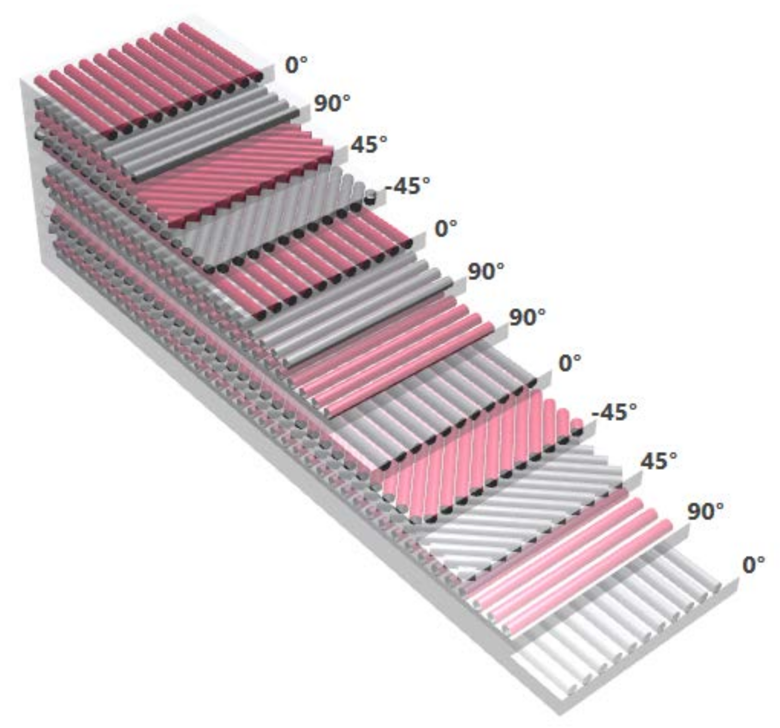
This study utilizes a Kevlar 49/epoxy composite with twelve plies in a cross-ply laminate configuration: [0/90/±45/0/90]s (as shown in
Figure 1). The composite material was thawed, unrolled, and cut to the desired sizes. The warp prepreg system resulted in a fiber volume fraction of 41%. Subsequently, the composite was cured at 4.13 bars and 175°C (Tg = 1600°C) for 24 hours under pressure and vacuum to produce hardened quasi-isotropic plates. Three plates measuring 300 mm x 300 mm were manufactured. These plates were then cut to a final size of 150 mm x 100 mm according to DIN 65561, with each ply having a thickness of 0.22 mm. The laminates were manufactured at Hellenic Airspace Industry facilities, strictly adhering to the manufacturer's specifications.
The mechanical properties of the materials used in this study are presented in
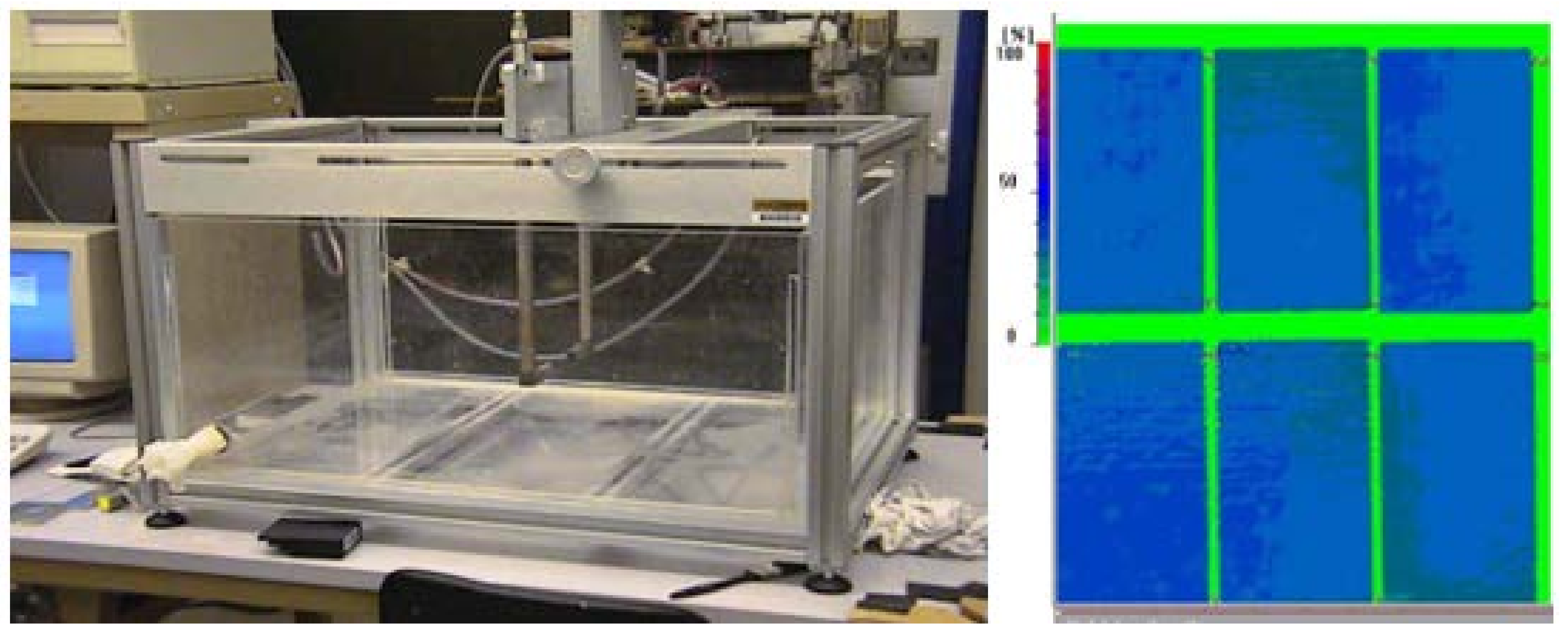
Table 1. Prior to impact testing, pristine specimens were examined using an ultrasonic scanner (
Figure 2). Ultrasonic C-scanning, a powerful non-destructive testing (NDT) method, was then employed qualitatively to investigate the damage distribution within the laminates and to compare their compressive failure modes.
2.2. Experimental Procedure
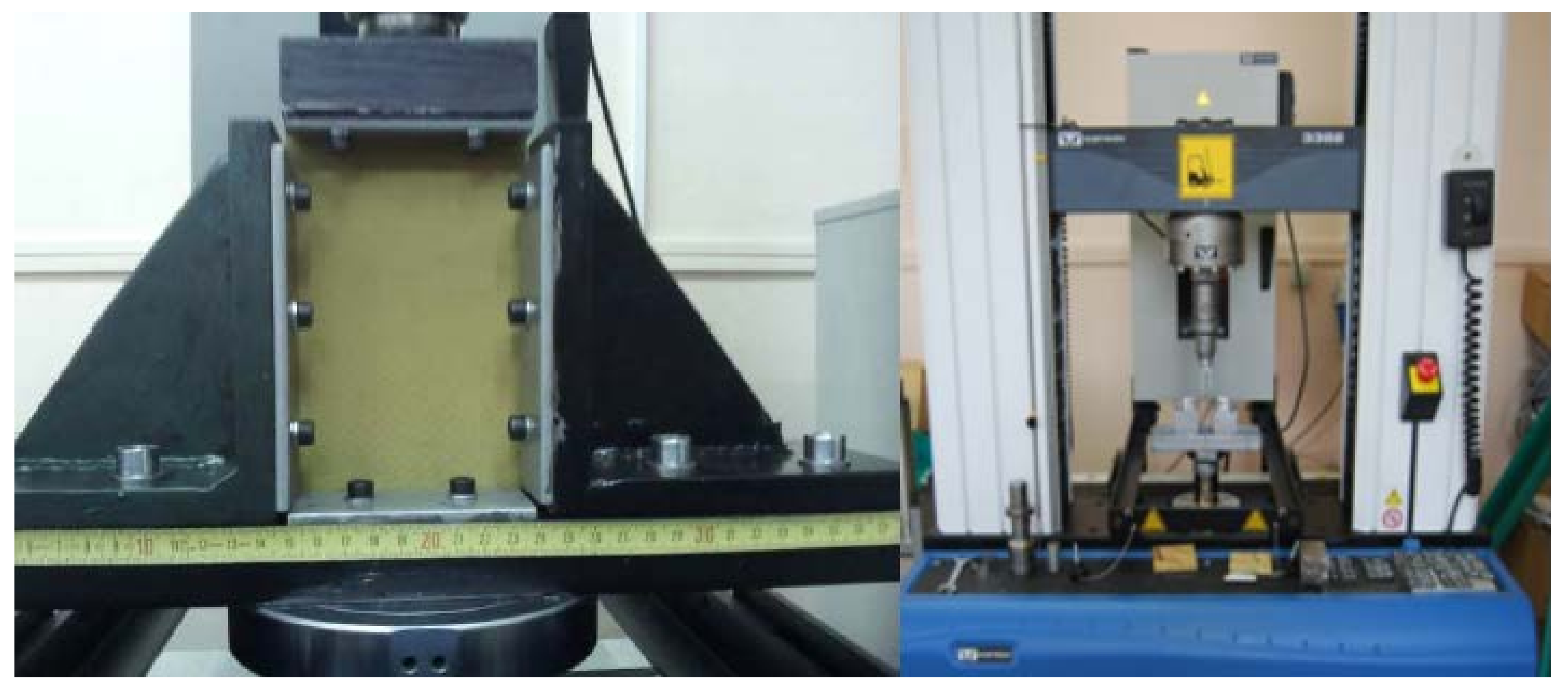
Following C-scanning, low-velocity impacts were performed on the specimens using a drop weight tower, Ceast 9350 (Instron, High Wycombe, England). Three specimens per impact energy level were impacted at 2, 4, 6, and 8 Joules per millimeter of specimen thickness. The specimens were clamped around their edges to prevent any misalignment. The impactor had a hemispherical tip with a diameter of 20mm and a total mass of 3kg. The impacted specimens were then scanned again using ultrasonic C-scanning to detect and visualize the subsurface delamination area within the composites. After C-scanning, all specimens were dried in an oven at 60°C for 24 hours to remove any residual water. A public domain image analysis software, ImageJ 1.45s (developed by Wayne Rasband), was used to accurately measure the total delamination areas from the C-scan images of the corresponding specimens. Finally, both impacted and pristine specimens were subjected to in-plane compression testing according to DIN 65561. This protocol specifies the use of a special anti-buckling jig made from high-strength steel (as shown in
Figure 3). An Instron 3382, 10 kN electromechanical universal testing machine was employed to obtain the compressive response of the specimens (both pristine and impacted) at a crosshead speed of 0.5 mm/min. The following equation was then used to determine the residual strength of the specimens:
where σ
c is the compression strength, F
max the maximum force applied, b the specimen width and d its thickness.
3. Finite Element Analysis
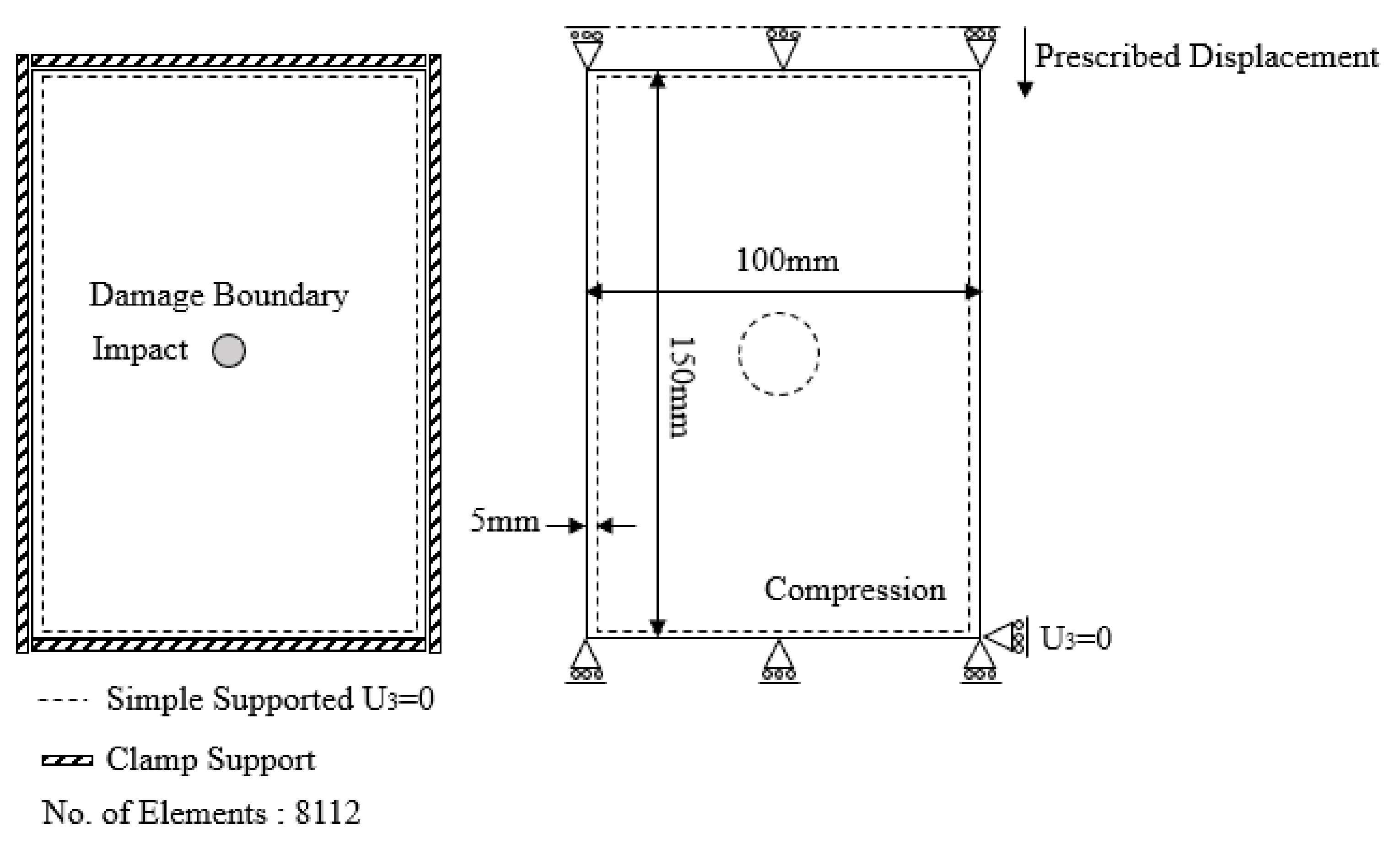
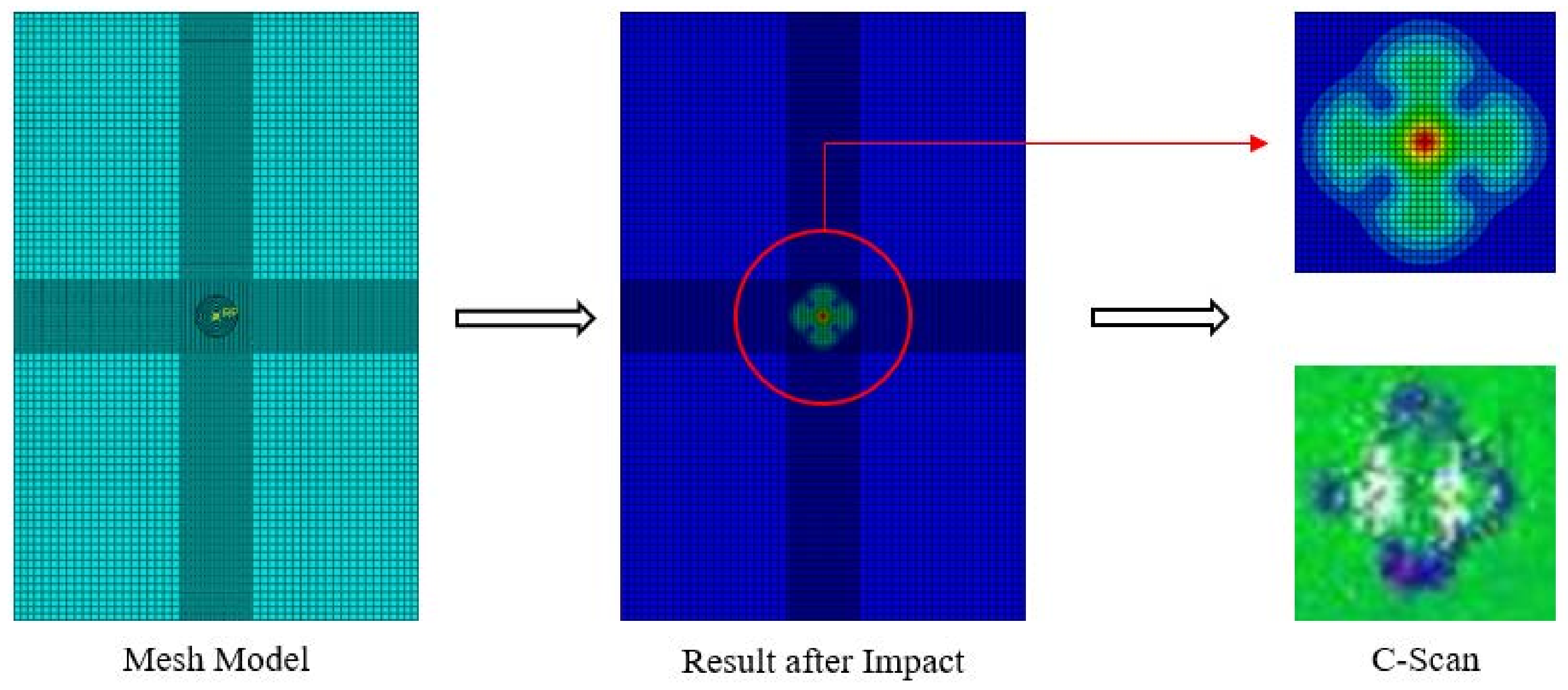
Abaqus software was used to perform a 3D finite element analysis of the damage in the specimens. Continuum shell elements were employed instead of conventional shell elements to model the plates. These elements offer two key advantages over conventional elements. First, they allow for more accurate contact modeling, leading to a better representation of the interactions between components during the simulation. Second, continuum shell elements can account for the behavior of plies stacked at different angles throughout the thickness of the plate, improving the capture of through-thickness response. An explicit solution scheme was chosen to avoid convergence problems, particularly during material degradation within the simulation. The boundary conditions applied to the model are shown in
Figure 4.
A more realistic approach to simulating a testing machine was implemented by applying a prescribed displacement incrementally to the joint, rather than applying nodal forces to each layer. This accounts for the fact that stresses in each layer depend on the overall stiffness of the composite [
24,
57,
58]. For this study, the impact-induced damage area is assumed to be circular. A more detailed discussion on damage area modeling can be found in the literature [
56,
59,
60]. The Hashin fabric failure criterion, a variant specifically designed for fabric-based materials, was adopted for this analysis. In woven composite panels, the 1 direction represents the warp direction, the 2 direction represents the weft direction, and the 3 direction corresponds to the through-thickness direction.
4. Results and Discussion
Experimental Results
The experiments were designed based on a special testing procedure developed by Boeing and Airbus to investigate the compressive response of impacted laminates according to the standards ASTM D 7137 and DIN 65561, respectively.
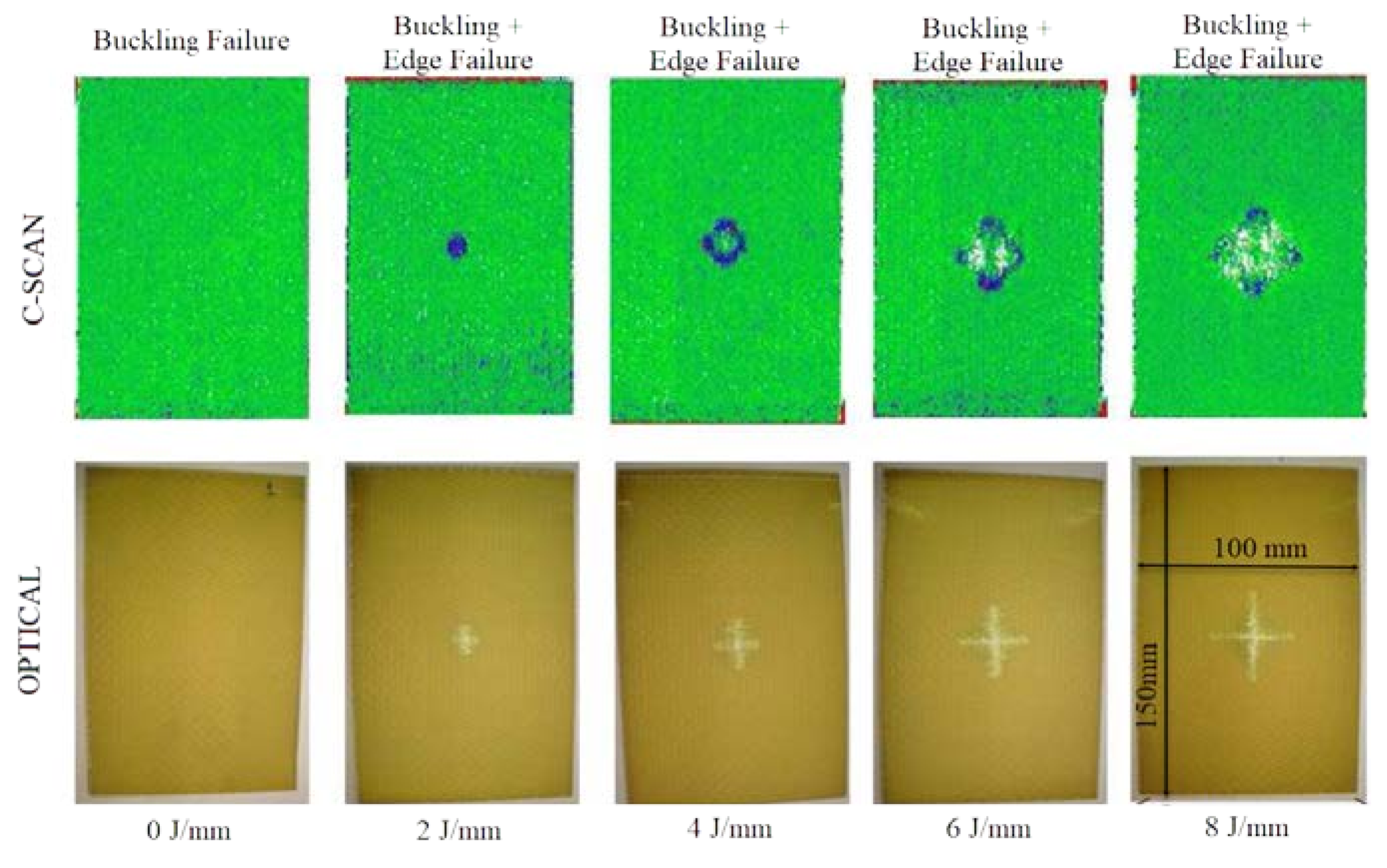
Figure 5 presents both optical and ultrasonic scans of the CAI-tested specimens at corresponding energy levels for comparison. This allows for a visual assessment of the damage caused by impact at different energy levels.
The ultrasonic scan images (lower row in
Figure 5) clearly show that the total delamination area increases with increasing impact energy levels. A typical delamination cross-section becomes visible in these images for impact energies above 0 J/mm. The optical macro-photographs reveal a differentiation in the failure modes with increasing impact energy. In-plane buckling and edge failure were observed for impact energies above 0 J/mm, while mid-plane fracture was not present in any of the plates. These results suggest that the internal damage is not severe enough to induce micro-buckling and subsequent ply failure leading to mid-plane fracture. It's important to note that the largest delamination under impact loading occurs between the 3rd-4th and 9th-10th plies (±45°). Within these delaminated zones, interfacial forces vanish under tensile and shear loading, and friction between the debonded surfaces is neglected.
Previous studies [
35,
61] have shown a complete loss of load-carrying capacity in the plies within the damaged area. For the range of impact energies investigated, matrix cracking was found to be the dominant form of intra-laminar failure, with minimal evidence of fiber breakage. Fiber damage was primarily observed in the top and bottom plies. The matrix cracking was concentrated around the impact region with a symmetrical and continuous distribution, similar to what has been reported elsewhere [
62]. The extent of matrix cracking increases proportionally with increasing impact energy. The interlaminar matrix damage contours for all plies at ultimate failure (shown in
Figure 5) confirm that damage propagates through the pre-damaged impacted center of the panel, which is consistent with experimental results [
63].
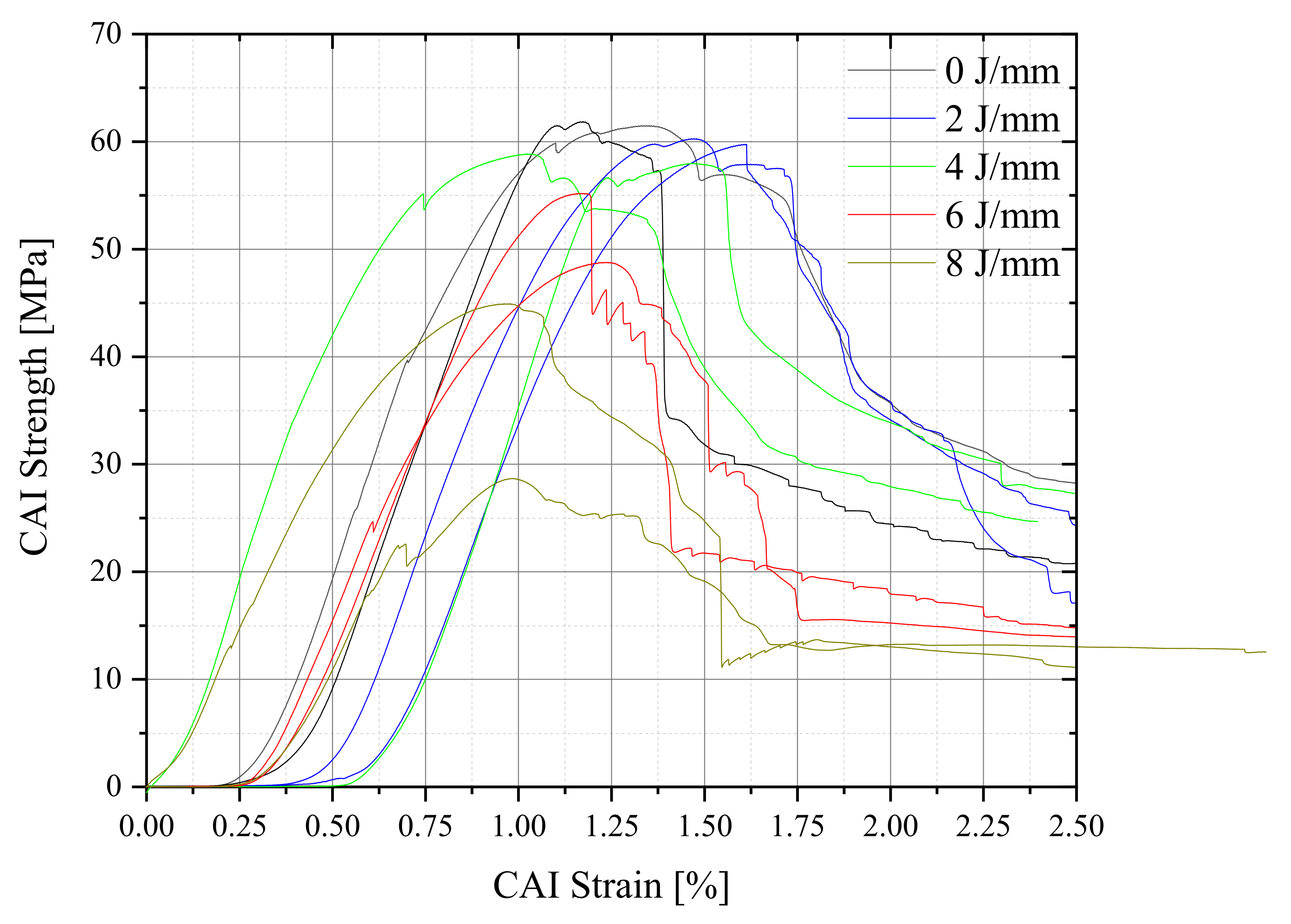
Figure 6 presents the experimental stress-strain curves obtained from the compression tests. It is evident that the varying impact energies significantly influence the in-plane compressive response of the Kevlar fiber laminates. The specimens generally exhibited a linear increase in stress with displacement until the ultimate strength of the laminates was reached. Beyond this point, a significant drop in stress occurred as catastrophic failure took place. This type of failure can be observed for undamaged laminates, while damaged laminates experienced central buckling before failure.
As shown in
Figure 5 and
Figure 6, the CAI strength decreases with increasing impact energy (
Table 2) [
6,
7,
8,
9,
24,
64,
65]. The maximum compressive stress and the buckling initiation stress (obtained from the linear extrapolation of the curves where the slope decreases) were recorded from these curves.
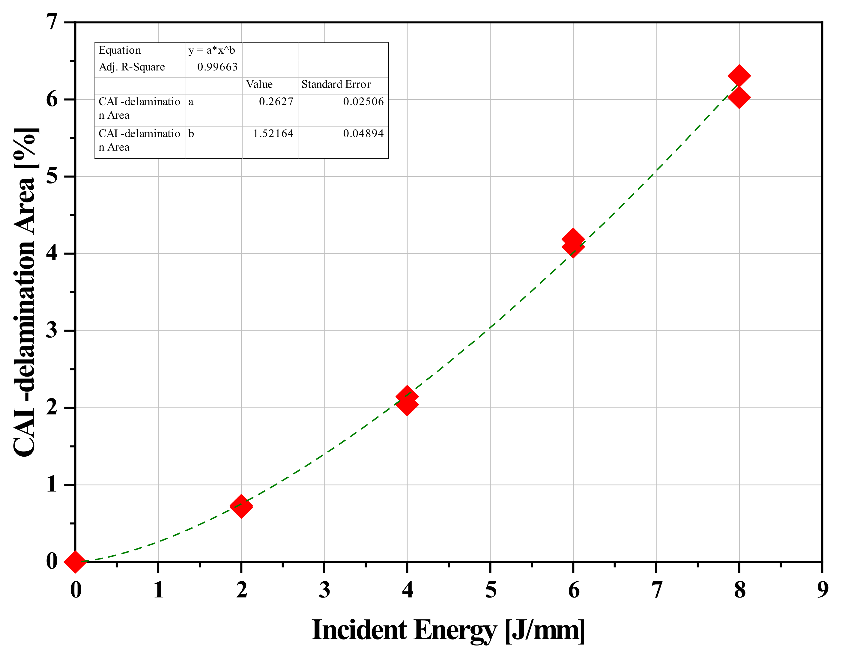
A non-linear correlation between impact energy (expressed per thickness mm) and total delamination area as measured by image analysis. This correlation was well-represented by a power law model, which provided satisfactory results. The power law model was of the type:
where: A
D= total delamination area, f=fit coefficient, I=impact incident energy, a=power law coefficient. The final equation of the model (R
2=0.98) was:
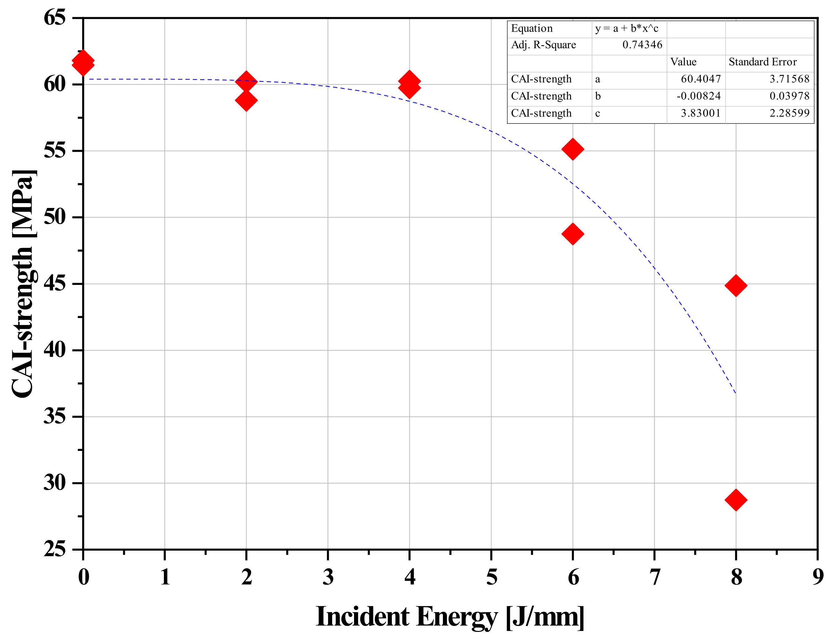
Figure 7 and 8 depict the remaining compressive strength plotted against impact energy for all specimens. Similar to the delamination area relationship, a linear trend is not observed. Instead, a power law relationship with a negative exponent appears to better describe the behavior of the experimental data. A significant reduction in the specimens' compressive strength is evident for impact energies above 0 J/mm of thickness. Finally,
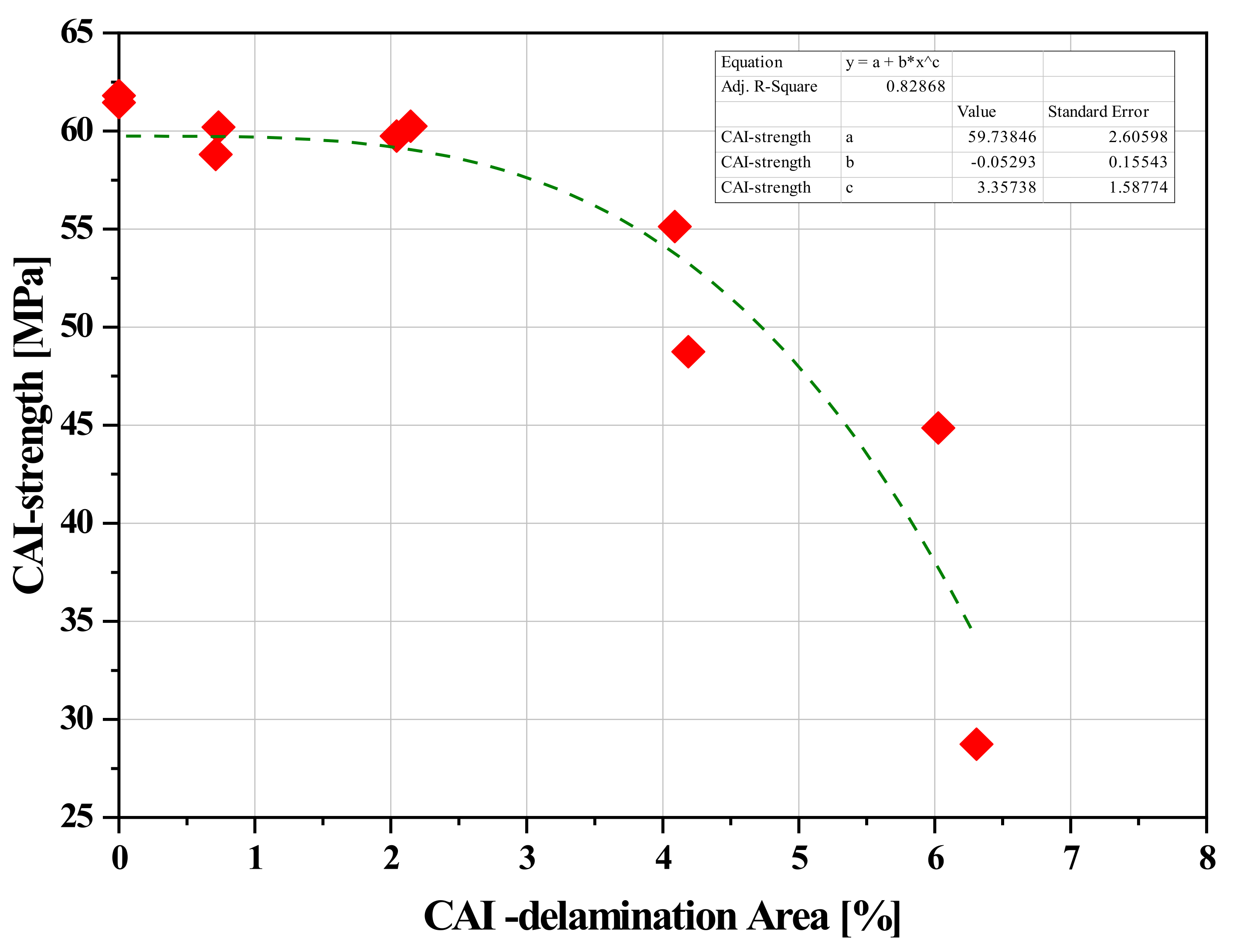
Figure 9 shows the CAI strength plotted as a function of the total delamination area. A sigmoidal (S-shaped) third-order polynomial was fitted to the experimental data. Interestingly, the graph reveals a plateau between 4% and 9% delamination area, indicating a relatively stable response in the specimens' strength. However, for delaminations exceeding 10% of the total specimen area, the CAI strength deteriorates rapidly.
Figure 7.
Cumulative Delamination Area vs Impact Energy.
Figure 7.
Cumulative Delamination Area vs Impact Energy.
Figure 8.
CAI Strength-Impact Energy for all specimens.
Figure 8.
CAI Strength-Impact Energy for all specimens.
Figure 9.
CAI Strength vs Total Delamination Area for all specimens.
Figure 9.
CAI Strength vs Total Delamination Area for all specimens.
The experimental results show that the CAI strength of undamaged (non-impacted) specimens with the [0/90/±45/90/0]s stacking sequence is 61.63 MPa. This value serves as the reference strength. When damage is limited to the impact zone, with no significant pre-buckling damage assumed, the buckling strength of the impacted specimens (treated samples at 8 J/mm) is 36.80 MPa. This lower reduction in strength might be attributed to the ±45° surface plies, which potentially act as a sacrificial layer, protecting the load-bearing 0° plies from impact damage [
66].
5. Finite Element Results
A rectangular plate measuring 100 mm x 150 mm with a ply thickness of 0.22 mm was modeled in the finite element software. Compressive loading was simulated by applying a prescribed vertical displacement to the top surface of the specimen.
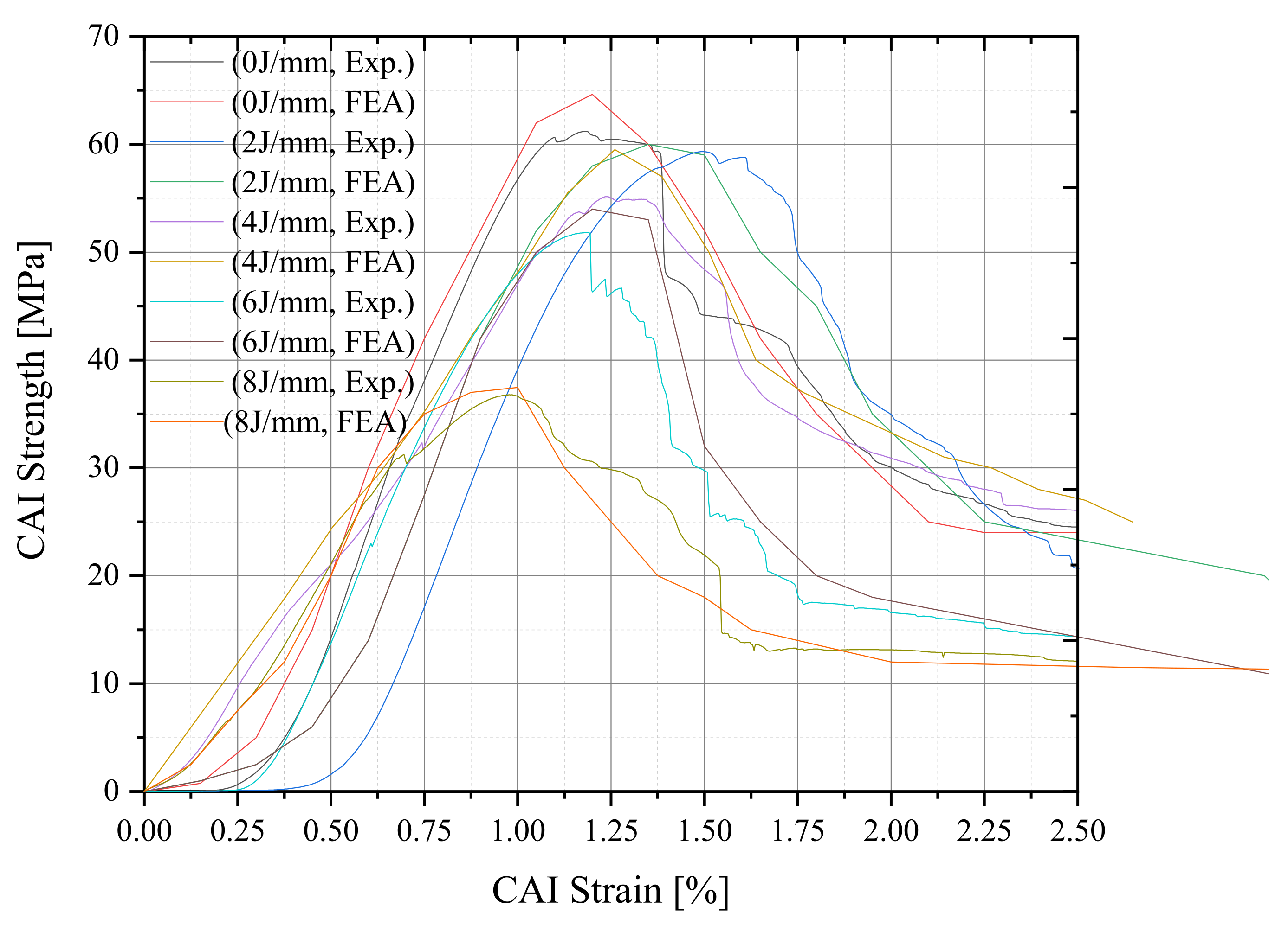
Figure 10 and
Figure 11 demonstrate good agreement between the experimental and numerical results. However, the theoretical buckling strength obtained from the finite element analysis for the impact-induced damage configuration overestimates the actual compressive strength observed in the experiments (
Figure 10). This discrepancy can be attributed to the assumptions made during the modeling process.
Following impact, the cross-ply laminates experience delamination, with the delamination area taking a circular shape and propagating primarily perpendicular to the loading direction (90°) [
67]. Other failure modes like buckling and fiber failure are also possibilities. However, incorporating information about the internal plies can significantly improve the accuracy of modeling these failure modes [
56,
68]. The results highlight two key observations regarding the impact response. First, the impact procedure induces permanent damage within the laminate. Second, analyzing plate failure solely through buckling calculations proves insufficient. While the anti-buckling jigs successfully prevented buckling, they lacked the rigidity to entirely suppress out-of-plane displacements. This highlights the limitations of buckling analysis as a standalone method for predicting post-impact behavior.
Finally, as shown in
Table 3, the theoretical buckling strength obtained from the finite element analysis for the impact-induced damage configuration overestimates the actual compressive strength observed in the experiments.
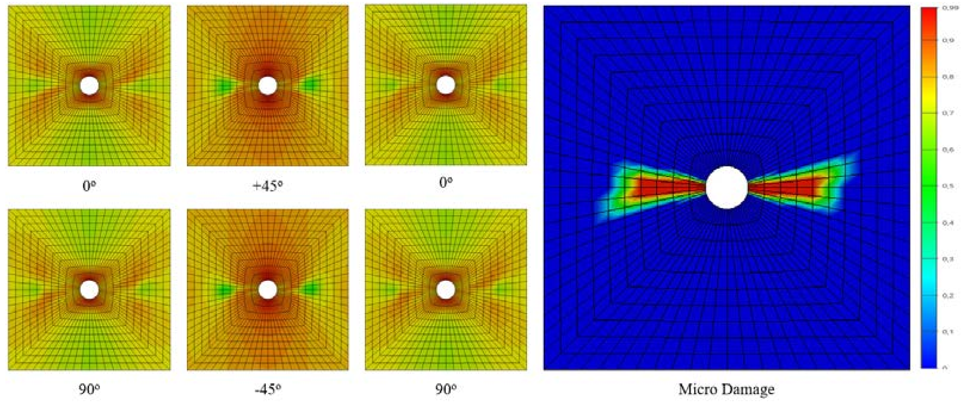
Two key parameters warrant further discussion based on the results: (a) crack propagation behavior during CAI simulation and (b) the presence of fiber cracking (
Figure 12).
6. Conclusions
This paper presents the results of a combined numerical and experimental investigation on Kevlar 49/Epoxy laminates. Six specimens were subjected to both impact and CAI (Compressive After Impact) tests, with impact energy levels ranging from 0 to 8 J/mm. The accuracy of the experimental results was validated through comparison with finite element analysis.
The investigation led to the following key conclusions:
The impact procedure induces permanent damage within the laminate, which is a critical factor influencing CAI failure.
In the finite element analysis, a simplified model was employed where the damage site was represented as an equivalent hole.
The anti-buckling jigs successfully prevented buckling during testing. However, these results highlight the limitations of analyzing plate failure solely through buckling calculations. Plate failure cannot be solely predicted by buckling behavior.
References
- Pelletier, J. L. and Vel, S. S., 2006, Multi-objective optimization of fiber reinforced composite laminates for strength, stiffness and minimal mass. Computers and Structures. 84: p. 2065–2080.
- Marble, E., & Boles, T. (2022). A Review of the Structural Characteristics of Aerospace Composites. Science Insights, 41(7), 749–753. [CrossRef]
- Aktas M, Karakuzu R, Icten BM. Impact behavior of glass/epoxy laminated composite plates at high temperatures. J Compos Mater 2010; 4(19):2289–99.
- Aktas M, Karakuzu R, Icten BM. Thermal impact behavior of glass–epoxy laminated composite plates. J Thermoplast Compos Mater 2011; 24(4):535–53.
- Liu, W., Zhao, X., & Li, S. (2020). A review of aerospace composite materials for high-performance structures. Composite Structures, 249, 112738.
- Carvelli, V., Fiore, V., & Micheletti, G. (2021). Progressive damage modeling for the prediction of the compressive after impact response of woven Kevlar® 49/epoxy composites. Composite Structures, 267, 114037.
- Gökçe, A., Çoban, M. Z., & Uysal, M. (2019). The influence of moisture absorption on the low-velocity impact and compression after impact (CAI) response of Kevlar 49® epoxy composites. Materials Science and Applications, 10(04), 301-313.
- Hitte, J., Périé, J. P., & Hemptinne, C. (2014). Experimental characterization of variable low velocity impact damage for flax fiber reinforced composites. Composites Part A: Applied Science and Manufacturing, 61, 188-196.
- Zhou, G., Wang, Z., & Huang, J. (2018). Numerical simulation of compression after impact (CAI) for CFRP laminates considering progressive damage. Composite Structures, 185, 42-53.
- Yang, H.H., 1993. Kevlar Aramid Fiber. Wiley, New York.
- Gökçe, A., Çoban, M. Z., & Uysal, M. (2020). Effect of surface modification on the low-velocity impact and compression after impact (CAI) response of Kevlar 49® epoxy composites. Journal of Composite Materials, 54(27), 4251-4267.
- Seyednejad, S. A., Rahmani, M., & Sultan, M. T. (2018). Kevlar® composites for ballistic applications: A review of ballistic impact mechanisms, influencing factors and material enhancements. Composites Part B: Engineering, 154, 238-258.
- Li, Y., Mamouri, H., Li, S., & Wang, Y. (2023). Effects of multi-scale reinforcements on the low-velocity impact and compression after impact (CAI) behaviors of Kevlar 49/epoxy composites. Composites Part B: Engineering, 134, 110253.
- Dong, Z., Sun, C.T., 2009. Testing and modeling of yarn pull-out in plain woven Kevlarfabrics. Compos. A Appl. Sci. Manuf. 40, 1863-1869.
- Pinho S, Iannucci L, Robinson P. Physically based failure models and criteria for laminated fibre-reinforced composites with emphasis on fibre kinking. Part II: FE implementation. Compos A Appl Sci Manuf 2006;37(5):766–77.
- Pinho S, Iannucci L, Robinson P. Physically-based failure models and criteria for laminated fibre-reinforced composites with emphasis on fibre kinking: Part I: development. Compos A Appl Sci Manuf 2006;37(1):63–73.
- Meddour, O., Mamouri, H., Guerrouache, M., & Benzeggagh, M. L. (2014). Prediction of the compressive response after impact of composite laminates using a damage mechanics approach. Composite Structures, 116, 556-567.
- de Freitas M, Reis L. Failure mechanisms on composite specimens subjected to compression after impact. Compos Struct 1998;42:365–73.
- Hosur MV, Murthy CRL, Ramurthy TS. Compression after impact testing of carbon fiber reinforced plastic laminates. ASTM J Compos Technol Res 1999;21:51–64.
- Naik NK, Joglekar MN, Arya H, Borade SV, Ramakrishna KN. Impact and compression after impact characteristics of plain weave fabric composites: effect of plate thickness. Adv Compos Mater 2004;12:261–80.
- Sanchu-Saez S, Barbero E, Zaera R, Navarro C. Compression after impact of thin composite laminates. Compos Sci Technol 2005;65:1911–9.
- Khondker OA, Leong KH, Herszberg I, Hamada H. Impact and compression after- impact performance of weft-knitted glass textile composites. Compos Part A: Appl Sci Manuf 2005;36:638–48.
- Cartie DDR, Irving PE. Effect of resin and fibre properties on impact and compression after impact performance of cfrp. Compos Part A: Appl Sci Manuf 2002;33:483–93.
- Liu, Y., Mamouri, H., Li, S., & Wang, C. (2022). Experimental and numerical investigation of the effect of fiber hybridization on the compressive after impact (CAI) behavior of Kevlar® 49/epoxy composites. Composite Structures, 272, 114320.
- Abrate, S. Impact on composite structures. Cambridge Univ. Press; 1998.
- Rouchon, J. Fatigue and damage tolerance aspects for composite aircraft structures. In: Proceedings of ICAF symposium, Delft; 1995.
- Rhead AT, Marchant D, Butler R. Compressive strength of composite laminates following free edge impact. Compos A Appl Sci Manuf 2010;41(9):1056–65.
- Choi HY, Chang K. A model for predicting damage in graphite-epoxy laminated composites resulting from low-velocity point impact. J Compos Mater 1992;26(14):2134–69.
- Naik NK, Joglekar MN, Arya H, Borade SV, Ramakrishna KN. Impact and compression after impact characteristics of plain weave fabric composites: effect of plate thickness. Adv Compos Mater 2004;12:261–80.
- Carvelli, V., Wegner, L., & Micheletti, G. (2018). Effect of stacking sequence and hygrothermal conditioning on the compressive after impact (CAI) response of woven Kevlar® 49/epoxy composites. Composites Part A: Applied Science and Manufacturing, 114, 305-317.
- Liu, X., Li, S., & Mamouri, H. (2019). Experimental investigation on the effect of stacking sequence on the compression after impact (CAI) behavior of flax/epoxy composites. Composite Structures, 222, 110942. (Focuses on Flax, but methodology applicable to Kevlar).
- Liu D, Raju BB, Dang XL. Size effects on impact response of composite laminates. Int J Impact Eng 1998;21:837–54.
- Dale M, Batiana BA, Carlsson LA. Low velocity impact and compression after impact characterization of woven carbon/vinylester at dry and water saturated conditions. Compos Struct 2012;94:1582–9.
- Gökçe, A., Çoban, M. Z., & Uysal, M. (2019). The influence of moisture absorption on the low-velocity impact and compression after impact (CAI) response of Kevlar 49® epoxy composites. Materials Science and Applications, 10(04), 301-313.
- Soutis C, Curtis PT. Prediction of the post-impact compressive strength of CFRP laminated composites. Compos Sci Technol 1996;56:677–84.
- Chai H, Babcock CD, Knauss WG. One dimensional modelling of failure in laminated plates by delamination buckling. Int J Solids Struct 1981;17:1069–83.
- Donadon MV, Iannucci L, Falzon BG, Hodgkinson JM, de Almeida SMF. A progressive failure model for composite laminates subjected to low velocity damage. Comput Struct 2008;86:1232–52.
- Maire JF, Lesne PM. An explicit damage model for the design of composite structures. Compos Sci Technol 1998;58:773–8.
- Iannucci L, Dechaen R, Willows M, Degrieck J. A failure model for analysis of thin woven glass composite structure under impact loading. Compos Strucut 2001;70:785–99.
- Williams KV, Vaziri R, Poursartip A. A physically based continuum damage mechanics model for thin laminate composite structures. Int J Solid Struct 2003:2267–300.
- Pavan RC, Creus GJ, Maghous S. A simplified approach to continuous damage of composite materials and micromechanical analysis. Compos Struct 2009;91:84–94.
- Donadon MV, de Almeida SFM, Arbelo MA, de Faria AR. A three dimensional ply failure model for composite structures. Int J Aerospace Eng 2009:22.
- Ianucci L, Willow ML. An energy based damage mechanics approach to modeling impact onto composite materials. Part I – Numerical models. Composite Part A: Appl Sci Manuf 2006(37):2041–56.
- Ianucci L, Willow ML. An energy based damage mechanics approach to modeling impact onto composite materials. Part II – Experimental and numerical results. Composite Part A: Appl Sci Manuf 2007(38):540–54.
- Johnson AF, Pickett AK, Rozycki P. Computational methods for predicting impact damage in composite structures. Compos Sci Technol 2001;61:2183–92.
- Iannucci L, Ankersen J. An energy based damage model for thin laminate composites. Compos Sci Technol 2006;66:934–51.
- Mamouri, H., Bessaieh, A., Laksimi, A., & Aidoun, Z. (2014). Experimental and numerical investigation of the compressive behaviour after impact of woven flax/epoxy composites. Composite Structures, 110, 346-355. (Published in 2014, but methodology applicable to Kevlar CAI modeling).
- Wang, Z., Zhou, G., & Huang, J. (2017). Progressive damage modeling for compression after impact of CFRP laminates. Composite Structures, 171, 372-383. (Published in 2017, but relevant for damage modeling concepts).
- Donadon MV. The structural behavior of composite laminate manufactured using resign infusion under flexible tooling (RIFT) process. PhD Thesis. Department of Aeronautics, Imperial College London; 2005.
- Falzon BG, Apruzzese P. Numerical analysis of intralaminar failure mechanisms in composite structures. Part I: FE implementation. Compos Struct 2011;93(2):1039–46.
- Falzon BG, Apruzzese P. Numerical analysis of intralaminar failure mechanisms in composite structures. Part II: applications. Compos Struct 2011;93(2):1047–53.
- Bouvet C, Rivallant S, Barrau JJ. Low velocity impact modeling in composite laminates capturing permanent indentation. Compos Sci Technol 2012;72(16):1977–88.
- Hongkarnjanakul N, Bouvet C, Rivallant S. Validation of low velocity impact modelling on different stacking sequences of CFRP laminates and influence of fibre failure. Compos Struct 2013;106:549–59.
- Rivallant S, Bouvet C, Hongkarnjanakul N. Failure analysis of CFRP laminates subjected to compression after impact: FE simulation using discrete interface elements. Compos A Appl Sci Manuf 2013;55:83–93.
- Mendes PAAE, Arbelo MA, Donadon MV, de Almeida SFM. Numerical modeling of compression after impact response of woven fiber-reinforced composites. In: Proceedings of 21st Brazilian Congress of, mechanical engineering; 2011.
- Ghorbani, M., Jafar, S. H., & Shariati, M. (2020). A progressive damage modeling approach for predicting the impact response and damage mechanisms of laminated composite plates. Composite Structures, 244, 112323.
- GC Papanicolaou, PJ Charitidis, DE Mouzakis, G Jiga. Experimental and numerical investigation of unbalanced boron/epoxy-aluminum single lap joints subjected to a corrosive environment. Journal of Composite Materials, vol. 50, 2: pp. 145-157. [CrossRef]
- GC Papanicolaou, PJ Charitidis, DE Mouzakis, E. Karachalios, G.Jigac, D.V.Portan, Experimental and numerical investigation of balanced Boron/Epoxy single lap joints subjected to salt spray aging. International Journal of Adhesion and Adhesives. Vol. 68, July 2016, Pages 9-18. [CrossRef]
- Hitchen SA and Kemp RMJ. The effect of stacking-sequence on impact damage in carbon–fibre epoxy com-posite.Composites1995; 26: 207–214.
- Soutis C and Curtis PT. Prediction of the post-impact compressive strength of CFRP laminated composites. Compos Sci Technol1996; 56: 677–684.
- Xiong Y, Poon C. A prediction method for the compressive strength of impact damaged composite laminates. Compos Struct 1995;30:357–67.
- Raimondo L, Iannucci L, Robinson P, Curtis P. A progressive failure model for mesh-size-independent FE analysis of composite laminates subject to low velocity impact damage. Compos Sci Technol 2012;72(5):624–32.
- Yan H, Oskay C, Krishnan A, Xu LR. Compression-after-impact response of woven fiber-reinforced composites. Compos Sci Technol 2010;70(14):2128–36.
- Zhang X, Davies GAO and Hitchings D. Impact damage with compressive preload and post-impact compression of carbon composite plates. Int J Impact Eng 1999; 22:485–509.
- Zhou, G. Effect of impact damage on residual compressive strength of glass fibre reinforced polyester (GFRP) laminates. Compos Struct 1996; 35: 171–181.
- Cantwell WJ, Morton J. The impact resistance of composite materials – a review. Composites 1991;22(5):347–62.
- Sanchez-Saez S., Barbero E., Zaera R., Navarro C. Compression after impact of thin composite laminates. Composites Science and Technology. V. 65, 2009, 1911-1929.
- Abdulhamid H, Bouvet C, Laurent M, Aboissiere J, Minot C. Numerical simulation of impact and compression after impact of asymmetrically tapered laminated CFRP. Open Archive Toulouse Archive Ouverte. [CrossRef]
|
Disclaimer/Publisher’s Note: The statements, opinions and data contained in all publications are solely those of the individual author(s) and contributor(s) and not of MDPI and/or the editor(s). MDPI and/or the editor(s) disclaim responsibility for any injury to people or property resulting from any ideas, methods, instructions or products referred to in the content. |
© 2024 by the authors. Licensee MDPI, Basel, Switzerland. This article is an open access article distributed under the terms and conditions of the Creative Commons Attribution (CC BY) license (http://creativecommons.org/licenses/by/4.0/).
