1. Introduction
Continuous carbon fiber reinforced metal composites are widely used in automotive, aerospace, electronic fields, due to their advantages of high temperature resistance, high strength, high modulus and low thermal expansion coefficient [
1,
2,
3,
4,
5]. The carbon fibers in the composites are usually straight or distributed at an angle in the metal matrix, the metal matrix usually has good plasticity, the elongation of the carbon fibers after fracture is small. When subjected to a large load, the carbon fiber can’t deform with the metal matrix. Although the strength of the composites has been improved, its ductility and toughness are greatly reduced [
6,
7,
8,
9].
The structure of helical shape widely exists in biological materials, such as wood, bamboo, bone, nacre, etc. [
10,
11,
12,
13,
14,
15,
16]. The structural characteristics of the material: Whether the components are continuous or discontinuous, they were distributed in a helical shape, and in layered with different helical directions and helical angles [
10,
15]. This helical structure composites have nonlinear stress-strain relationships and large Poisson’s ratios [
17,
18]. Compared with straight fiber composites, the helical fiber composites can extension in the axial direction of the helical fibers, through helical fiber uniform bending and torsion, when an axial load was applied [
19,
20,
21,
22]. The shape of helical fiber can change cooperatively with the deforming metal matrix in a certain extent. The latter load is transmitted to the fiber through the matrix and the interface between the fiber and the matrix. When the load exceeds the maximum load, the composites will appear defects such as interface delamination, fiber fracture and so on. Therefore, such composite materials with the helical shape structure have properties such as high strength and high toughness at the same time.
Li [
23,
24] et al. prepared helical fiber reinforced resin matrix composites by fixing fibers with steel wires. The composites with the double helical fiber structure have the best comprehensive mechanical properties compared with other structures composites. Kagawa [
25] et al. prepared the helical tungsten fiber reinforced Copper matrix composites by electrodeposition and vacuum hot-pressing methods. During the deformation and fracture of composites, the helical fibers were deformed and fractured, deflected the crack propagation direction, energy absorption was increased, the toughness of the composites were increased. Wang [
21,
22] et al. studied the helical fiber reinforced composite through finite element simulation. Due to the uniform bending and twisting of the helical fiber in the composites during the deformation process, the pull-out force of the fiber was increased, which increases the toughness of the composites. Chang [
26] et al. prepared a helical nylon fiber reinforced epoxy resin matrix composite by winding nylon wire into a helical shape and fixing the shape by heating. The toughness and strength of the composites were both improved.
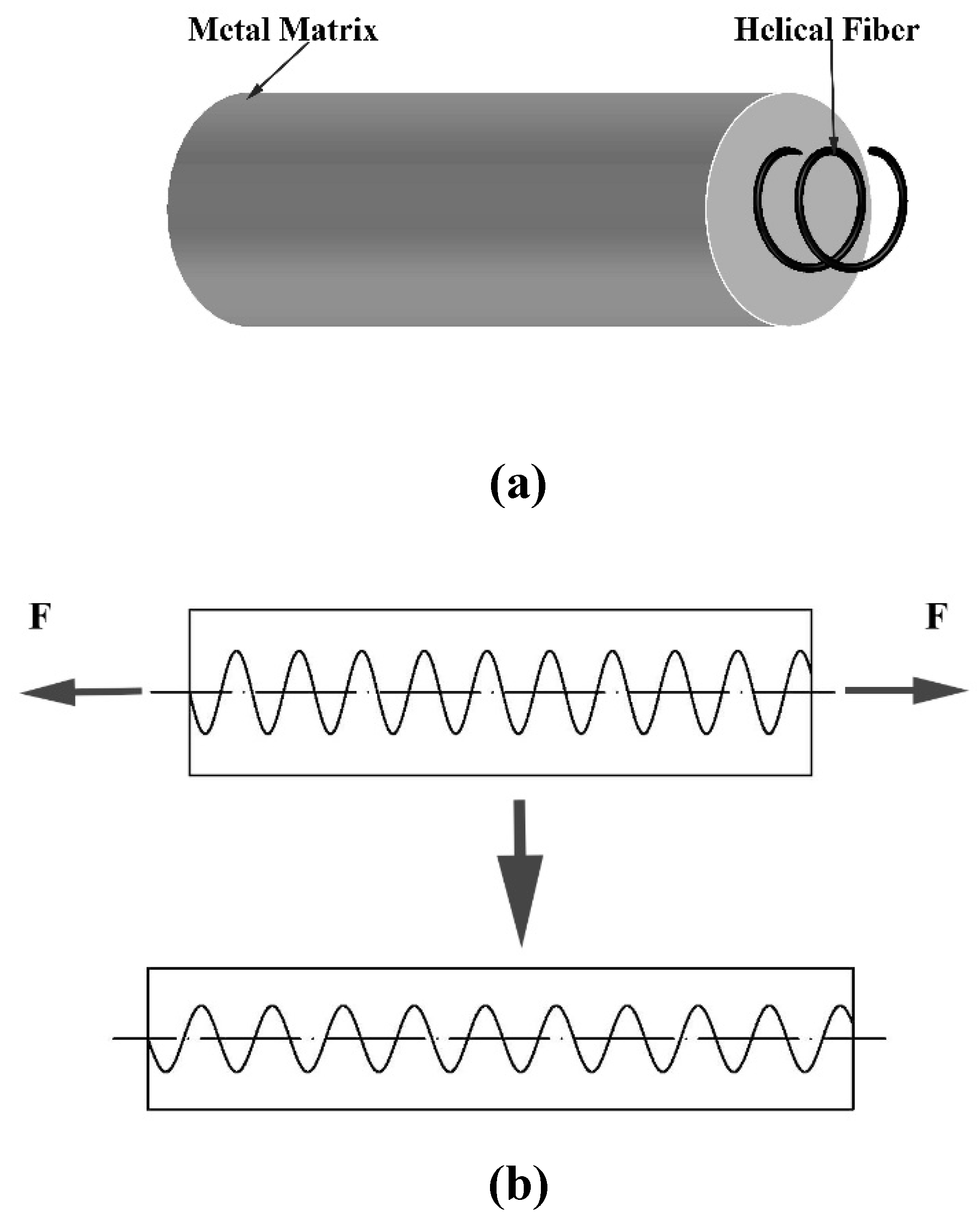
In summary, the helical shape reinforced phase composites have high strength and high toughness at the same time. For helical carbon fiber reinforced metal matrix composites, the metal matrix has high strength and ductility, which is different from the resin matrix. When the composites was subjected to axial load, the shape of the helical carbon fiber can change with the metal matrix plastic deformation, that is, the pitch was increased and the helical radius was decreased, as shown in
Figure 1. As the angle between the carbon fiber direction and the tensile direction decreases, the tensile strength of the composites increases. When the carbon fiber shape becomes nearly straight after the large axial extension, the composites has the maximum tensile strength. It shows that the composite can has the advantages of high strength and high ductility at the same time.
Carbon fibers are usually soft and cannot maintain the helical shape without any treatment. Most of the preparation processes of metal matrix composites are under high temperature and high pressure. Whether winding the carbon fiber on a metal rod or fixing the carbon fiber in the helical shape with a high melting point metal wire, to prepare the helical carbon fiber reinforced metal composites. Liang[
27] et al. proved that the helical carbon fiber can deform with the deformation of the matrix through simulation and drawing experiments. However, the helical carbon fiber reinforced aluminum matrix composite is prepared by winding carbon fiber on the central aluminum rod and casting a layer of aluminum on the outer layer. There is an oxide layer between the central rod and the outer cast aluminum, which is prone to delamination during drawing process., which reduced the performance of the composites. Using powder metallurgy, carbon fibers can be fixed into a helical shape at room temperature, and then processed by pressing, sintering, etc. to prepare helical carbon fiber reinforced metal matrix composites. However, powder metallurgy is not suitable for easily oxidized metals (Al, Mg, etc.) There are disadvantages of the powder metallurgy, such as powder particles difficulty to bonding as the powder oxidation, poor ductility and complex process [
28,
29,
30].
In a word, the existing research on helical fiber reinforced composites shows that the matrix of composite materials is mostly organic plastic, and the reinforcement is helical fiber between macro and micro size. The properties of this composite material are studied by simulation, theoretical analysis and experiment. There are few studies on macro size helical fiber-reinforced metal composites. At the same time, it is difficult to maintain the helical shape of the fiber, the size of the composites is limited, it is difficult to continuous production, and the new second phase (oxide layer, high melting point metal) introduced in the preparation process affects the performance of the composite. Therefore, how to continuously and stably prepare helical fiber reinforced metal matrix composites is an urgent problem to be solved.
In this paper, the continuous casting process as a novel process, which to prepare the helical fiber reinforced metal matrix composites, which is referred to as HFCC (Helical Fiber Composites Continuous Casting Process). The effect of continuous casting parameters on the morphology of helical carbon fiber was studied by preparing helical carbon fiber reinforced lead matrix composite Through the method of analytic geometry, the model between the process parameters and the geometric parameters of the helical shape in the composites is established. The shape of helical fiber reinforced metal matrix composites can be controlled by process parameters. The helical carbon fiber reinforced aluminum matrix composite as the helical carbon fiber reinforced metal matrix composite material practical application initial study was prepared. The helical carbon fiber reinforced aluminum matrix composites were prepared. The interface between the aluminum matrix and carbon fiber, the mechanical properties of the composites were studied.
2. Experiment
2.1. Design and Manufacturing of Experimental Equipment
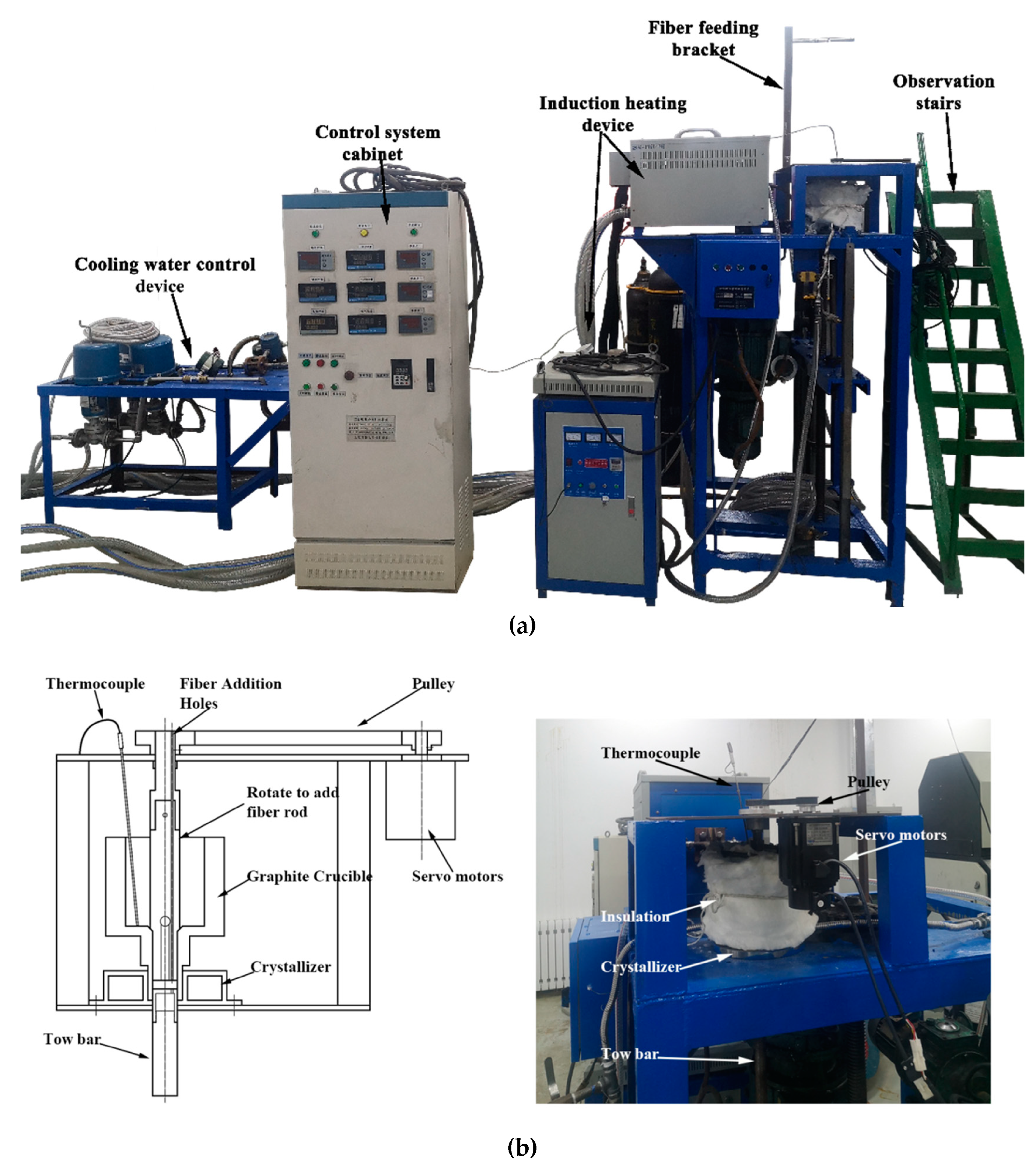
The equipment includes a cooling water control device, a continuous casting traction device, an induction heating device, and a fiber rotating device, as shown in
Figure 2. The cooling water control device of the crystallizer is provided with water pressure by the water pump, and the magnetic control valve controls the water flow, the range is 100~1000L/h. The continuous casting traction device is composed of a three-phase asynchronous motor, a reducer and a lead screw, to obtain a stable drawing speed, the speed range is 5~100mm/min. The induction heating equipment provides metal melting and continuous casting temperature with a temperature deviation of ±5°C. Some PID control instruments which are placed in the control cabinet to display and control cooling water intensity and melt temperature which heated by induction heating device. The fiber rotation device is to make the fiber rotate smoothly into the molten metal. Melting temperature was measured with a K-type thermocouple protected by a ceramic tube. The observation stairs are to easily observe the operation of the experimental equipment.
The rotate to add fiber rod is a graphite rod with an eccentric hole. It rotates under the drive of a servo motor. The motor speed range is 1-3000rpm. The gear ratio between the driving pulley and the driven pulley is 2:3. The rotational speed of the motor is displayed on the drive. The tow bar which is pulling the solidified metal has fixed fiber holes, which are the same as the fiber rotation radius.
2.2. Material
Pure lead and commercial pure aluminum are selected as metal matrix respectively. Carbon fiber is provided by Weihai Guangwei Composites Materials Co., Ltd. (China),which bundles are 6000.
2.3. Process Parameters
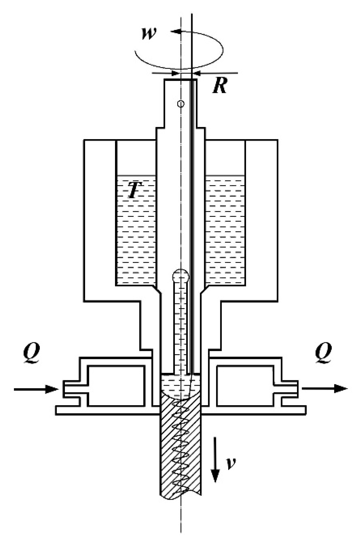
According to the characteristics of the experimental equipment, the process parameters mainly include fiber rotation speed
w(
), fiber rotation radius
R(mm), melt temperature
T(
), cooling intensity
Q(
) and continuous casting speed
v(
), as shown in
Figure 3.
The melting point of pure lead is 327°C. The melt temperature in continuous casting is relatively low, so carbon fiber does not need any protection of inert gas. The melting point of industrial pure aluminum is 660
. In order to keep carbon fiber from being not burned by oxygen in the air at high temperatures, Carbon fiber should to be protected by
gas during the preparation process. The determined range of process parameters of helical carbon fiber reinforced lead composites, as shown in
Table 1.
The continuous casting speed was fixed at 5.5 mm/min. At the condition of low continuous casting speed, the liquid-solid interface metal shape of solidification is close to the horizontal plane, which is easier to the formation of the helical shape of the fiber in the lead matrix, so only a lower continuous casting speed is selected in this experiment. Due to the limitation of mold size, only one carbon fiber rotation radius is selected.
3.3. Testing
3.3.1. The Shape of Helical Carbon Fiber in Composites
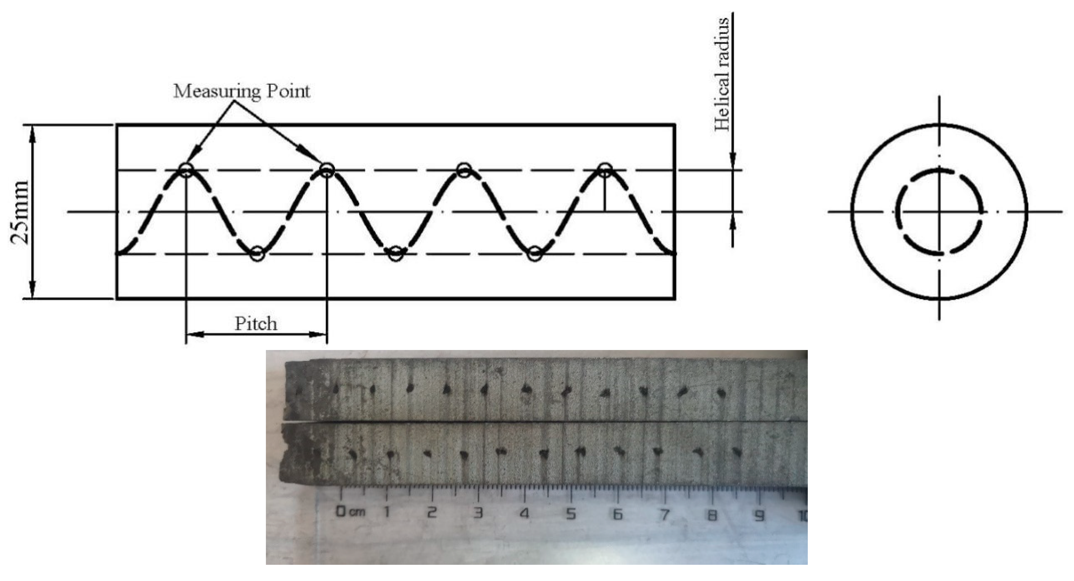
The sample with a diameter of 25 mm was equally divided into four parts along the axial direction, as shown in
Figure 4. The distance between adjacent measurement points is the pitch of the helical fiber, and the distance between the measurement point and the centerline of the bar is the helical radius of the helical fiber in composites.
3.3.2. Interface and Mechanical Property of Helical Carbon Fiber Reinforced Aluminum Matrix Composites
The interface of the carbon fiber reinforced aluminum matrix composite was observed by scanning electron microscope. The tensile test was carried out at room temperature at the rate of 0.5mm/min. The mechanical properties of the composite were tested.
3. Model
According to whether it affects the liquid-solid interface height in the crystallizer, the process parameters are divided into two types: The first, melt temperature, cooling intensity and continuous casting speed. The second, fiber rotation speed and rotation radius. The former changes the liquid-solid interface height, the latter does not. The shape of the helical fiber in composites is affected by the height of the liquid-solid interface and the frequency of fiber addition.
Taking the height of the liquid-solid interface as an important parameter, the process of forming a shape of the helical fiber in the metal matrix is quantitatively analyzed. When the fiber is in a state of motion equilibrium, the relationship between the process parameters and the geometry of the helical fiber and the process parameters is established. That is, the process model.
3.1. Coordinate System
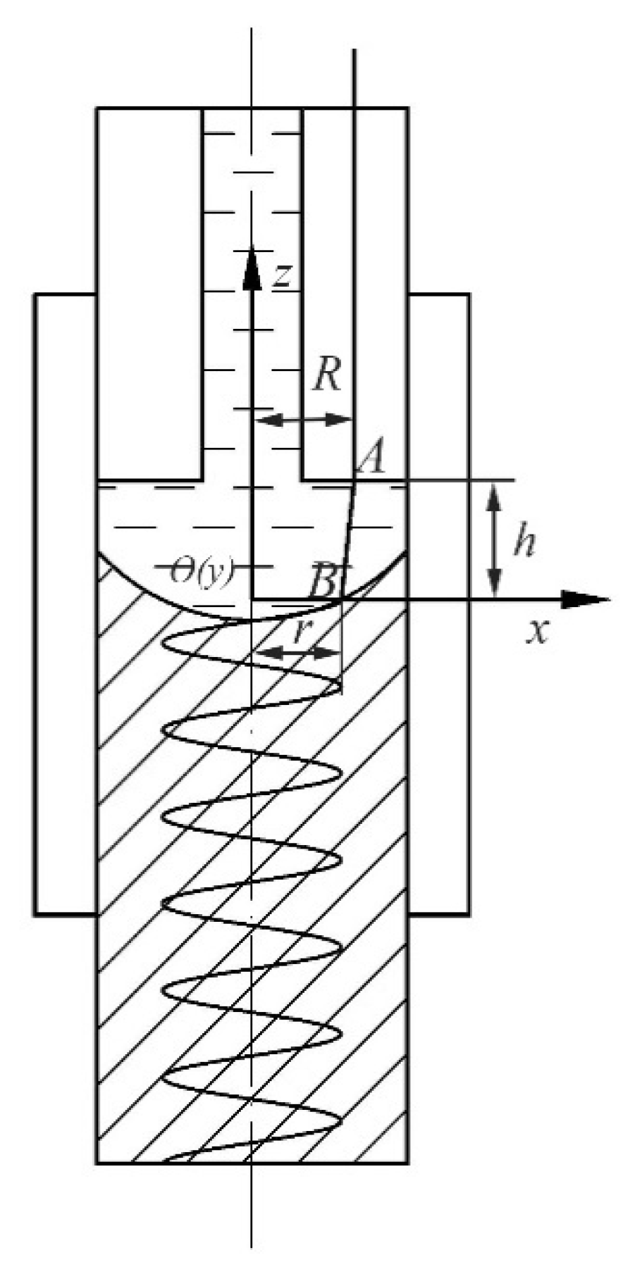
Take the horizontal plane where the fiber and the solidified metal bond point as the
O-xy plane of the 3D space Cartesian coordinate system, the central axis of the continuous casting rod is the z-axis direction, the origin is the intersection of the
O-xy plane and the
z-axis, a 3D space Cartesian coordinate
O-xyz was established, as shown in
Figure 5. The fiber rotates around the
z-axis with a radius R to form the fiber rotation plane. Under the condition that the process parameters remain unchanged, the distance between the
O-xy plane and the plane of rotation of the fiber in the matrix is remain stable, which is recorded as the height of the liquid-solid interface
h in this paper.
A and
B are the fiber rotation point and the metal bonding point, respectively.
r is the helical radius of the helical carbon fiber in the solidified metal matrix.
3.2. Basic Assumptions
The basic assumptions of this process model:
The first, the cooling intensity of the crystallizer is uniform, that is, the liquid-solid interface is rotationally symmetrical around the z-axis. If it is not, the radius of the helical shape will be unstable;
The second, during the continuous casting, the melt temperature is stable, the fluctuation of the position of the solid-liquid interface was neglected. The continuous casting speed is low, the liquid-solid interface is close to the plane, and the concave shape of the liquid-solid interface is ignored. At any radial position, h is constant value;
The third, during the continuous casting, the tension on fiber is stable, that is, the solidification and bonding process of the fiber and the metal is stable. The fiber is straightened in the molten metal. The excessive tension causes the bonding point to be pulled away. On the contrary, the fiber in the molten metal is in a relaxed and bent state.
3.3. The Formation Processing of Helical Fiber
3.3.1. Initial State
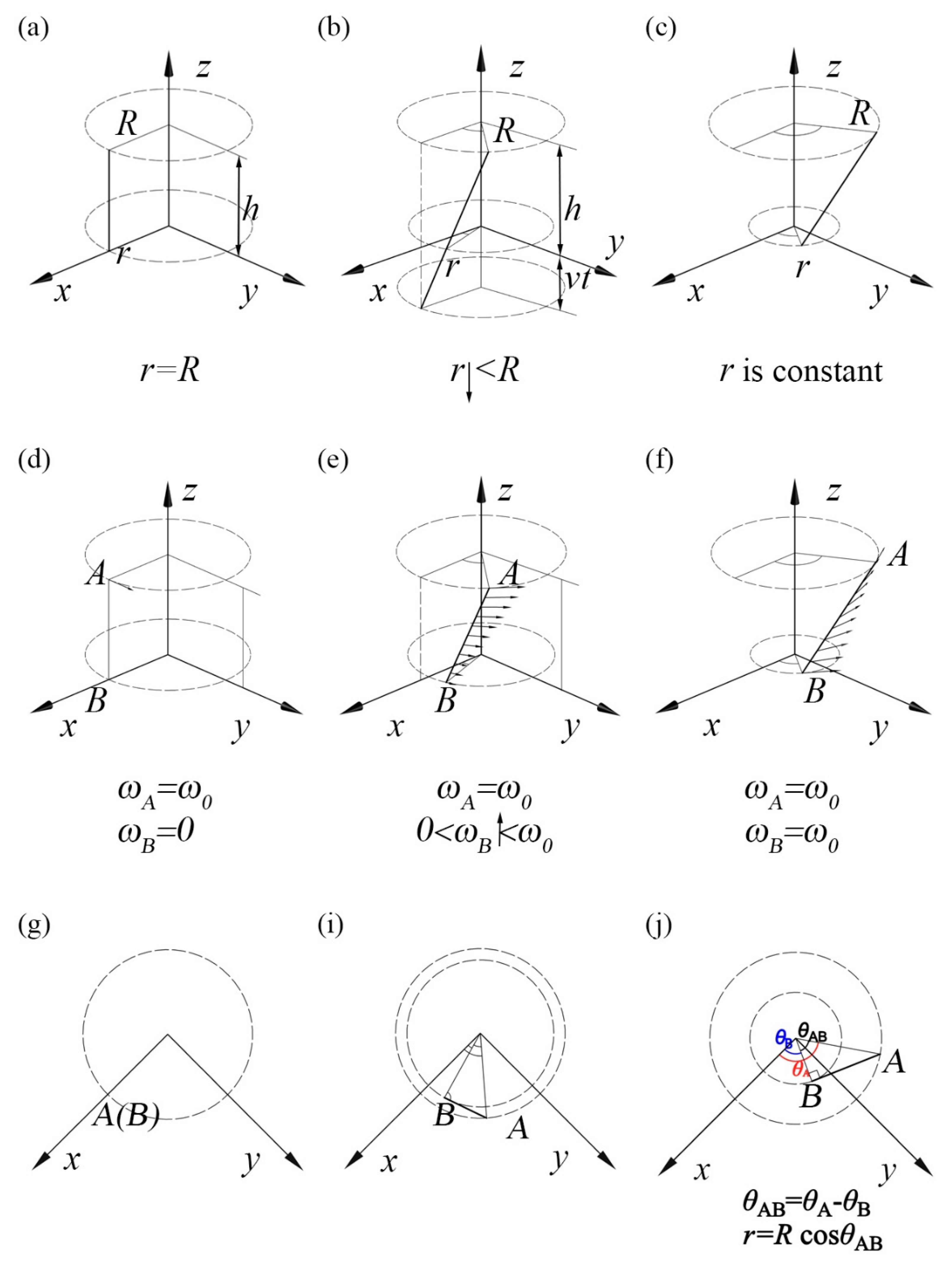
In the initial state of continuous casting, the fiber does not start to rotate. The height of the liquid-solid interface formed in the crystallizer is stable. the radius of the fiber in the metal matrix is the same as the fiber rotation radius
R. When the fiber starts to rotate counterclockwise, only the speed of the fiber rotation point A is
, the speed of the fiber-metal bonding point B is zero. In the top view, the fiber rotation point A and the fiber-metal bonding point B are the same point, as shown in
Figure 6(a), (d), (g).
3.3.2. Transition State
As the carbon fiber rotates with the speed
, the solidified metal matrix was pulls down. The original fiber-metal bonding point B was drops at the continuous casting speed
.The metal above the solid-liquid interface is liquid, and its fibers are inclined in the liquid metal at a certain angle to the horizontal plane, as shown in
Figure 6(b). Since the distance
h between the two planes which were the carbon fiber rotation plane and the horizontal plane include the bonding point B remains unchanged. The bonding point of the carbon fiber and solidified lead metal gradually decreases. The horizontal rotation speed of the bonding point B also gradually increases from the initial zero. However, with increasing the speed of point B, the difference between the angle turned by point A and the angle turned by point B becomes larger. The larger the angle difference, the smaller the radius of the bonding point. The top view is shown in
Figure 6 (i).
3.3.3. Stable State
With the carbon fiber rotation, the difference
between the angle
of point A rotation and the angle
of the point B rotation in the horizontal direction continues to increase. When the rotational speed of the point B increases to
in the horizontal direction,
increases to the maximum and remains constant. At this time, the straight-line AB where the fiber is located is tangent to the circle formed by the bonding point B, and reaches a stable state, as shown in
Figure 6(j).
In this stable state, the straight-line AB is at fixed angle to the horizontal plane xOy rotate around the z-axis. The bonding point B is formed by the combined action of the rotation around the z-axis at the horizontal rotation speed and the movement along the negative direction of the z-axis at the continuous casting speed . The fibers were arranged in a helical shape in the metal matrix.
According to the positional relationship, the helical radius
r and the helical pitch
H of the helical carbon fibers in the matrix are respectively.
Where R is the carbon fiber rotation radius rotate round the z-axis, and is the difference between the angle of the carbon fiber rotation point A and the angle of the bond point B rotation, when the steady state is reached. is the time for the carbon fiber to one rotation, is the continuous casting speed, and is the rotational speed of the fibers at the direction of horizontal.
geometric relationship: initial state(a)formation process(b)stable state(c);
speed change of fiber binding point: initial state(d)formation process(e) stable state(f);
the top view of the geometric relationship: initial state(g)formation process(i)stable state(f);
3.4. The Angle of Difference between Point A and Point B ----
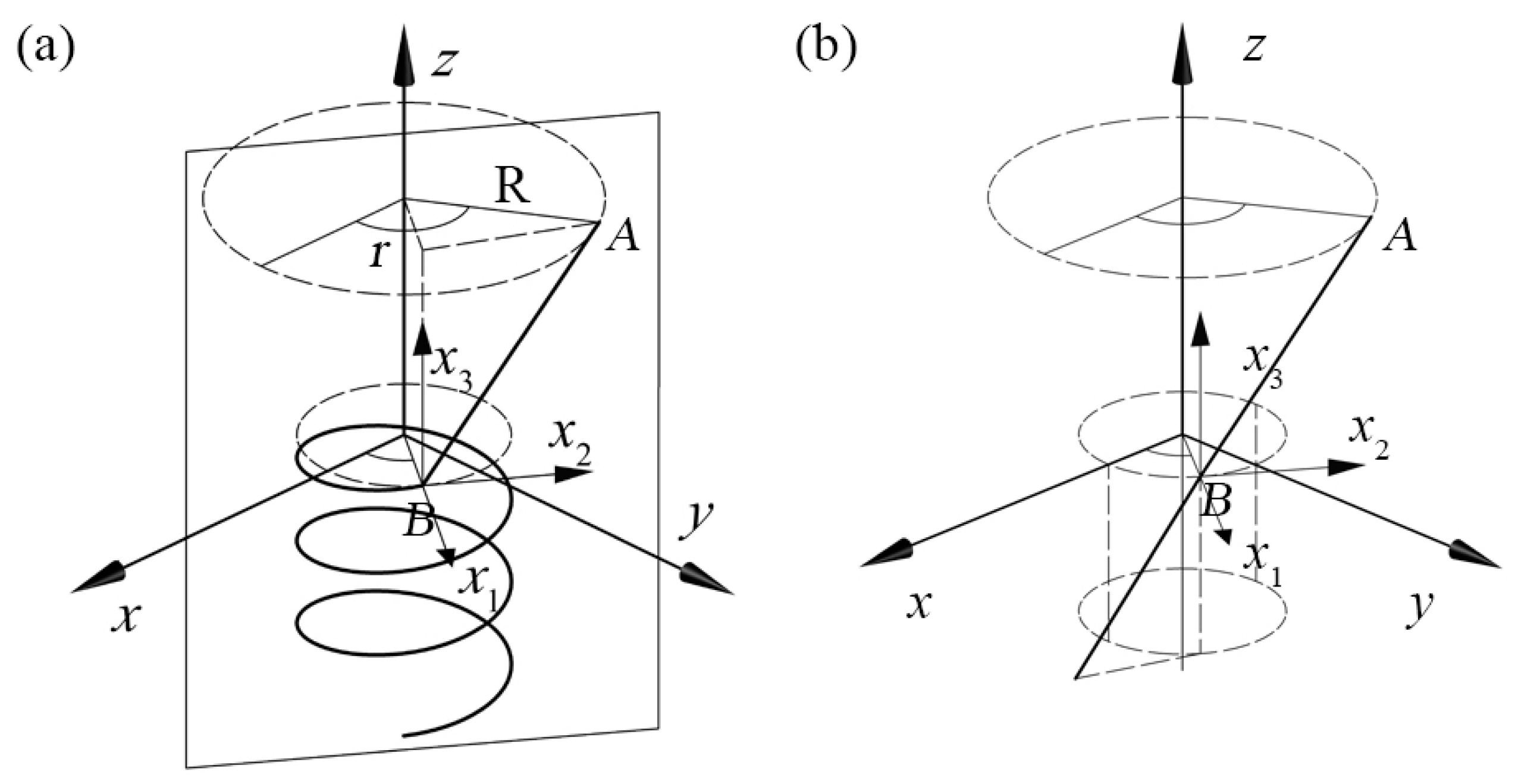
When the helical fibers in the metal are stably formed, the fiber between the fiber rotation point A and the fiber-metal bonding point B is at a fixed angle to the horizontal plane, as shown in
Figure 7(a). The helical fibers in metal matrix are unfolded, which are extensions of the fibers AB in the liquid metal, as shown in
Figure 7(b).
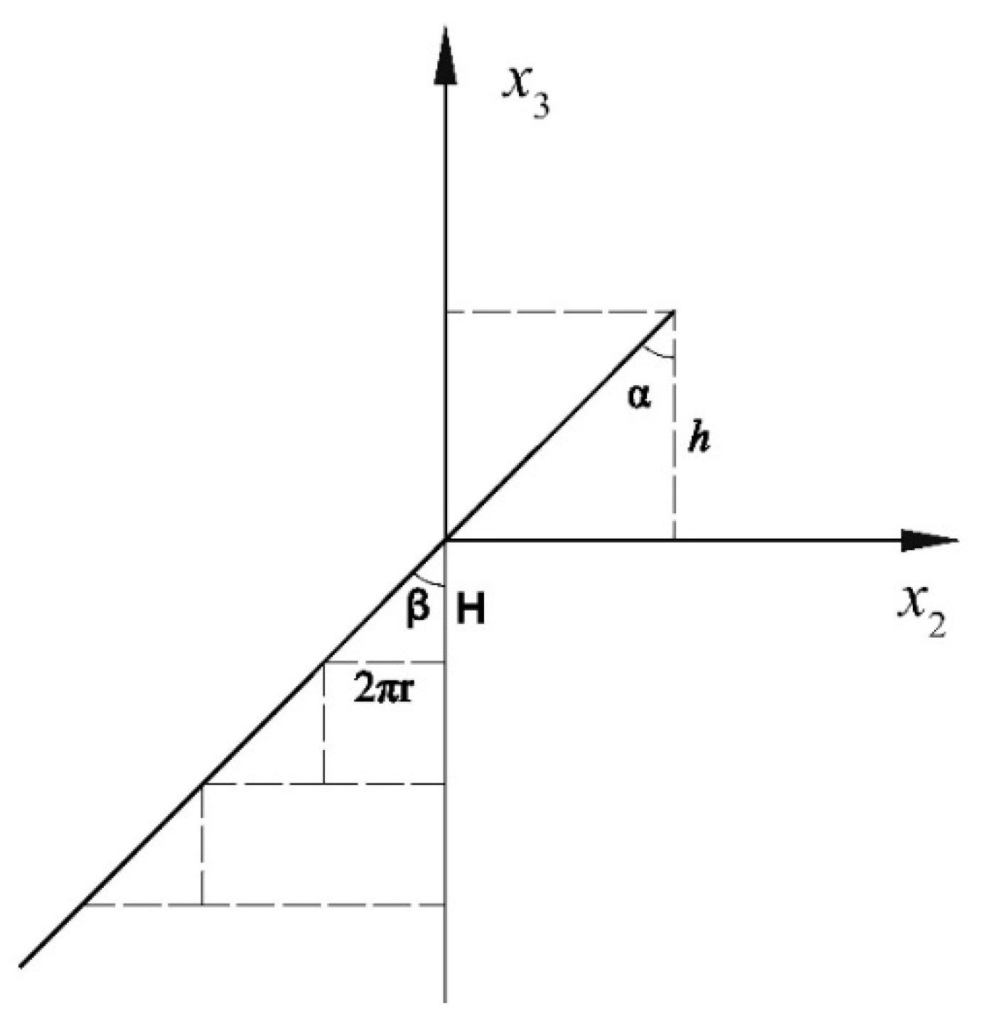
The coordinate system of
Figure 8 is established on the plane where the straight fiber AB is located,
In the
Figure 8,
β is the helical angle of the helical fibers in the metal matrix,
is the angle between fiber AB in the liquid metal and
z-axis. According to the geometric relationship in
Figure 6(j) and
Figure 7(a).
where
α=β, from Equation.(4) and (5) follow that
The helical radius of the helical fiber in metal matrix,
The pitch of the helical fiber in metal matrix,
This process model quantitatively describes the relationship between process parameters and the shape of helical fiber in the metal matrix: The helix radius r is determined by the fiber rotation radius R, the height of the liquid-solid interface h, the fiber rotation speed , and the continuous casting speed .The pitch H is determined by the continuous casting speed and the fiber rotation speed .
Among these process parameters, the liquid-solid interface height h is mainly related to the metal type, continuous casting process parameters (melt temperature, cooling intensity and continuous casting speed, etc.), the boundary conditions of crystallizer (the dimensions of continuous casting equipment), which can be measured by experiments.
4. Results and Discussion
4.1. Shape Stability of Helical Carbon Fiber in Lead Matrix
According to the above process model, the shape stability of the helical carbon fiber in the helical carbon fiber reinforced lead matrix composites is mainly affected by the state of the liquid-solid interface. The state of the liquid-solid interface mainly includes the symmetry and height stability of the liquid-solid interface. The symmetry of the liquid-solid interface is mainly related to the cooling uniformity of the crystallizer. The height stability of liquid-solid interface is mainly related to the stability of melt temperature and continuous casting speed.
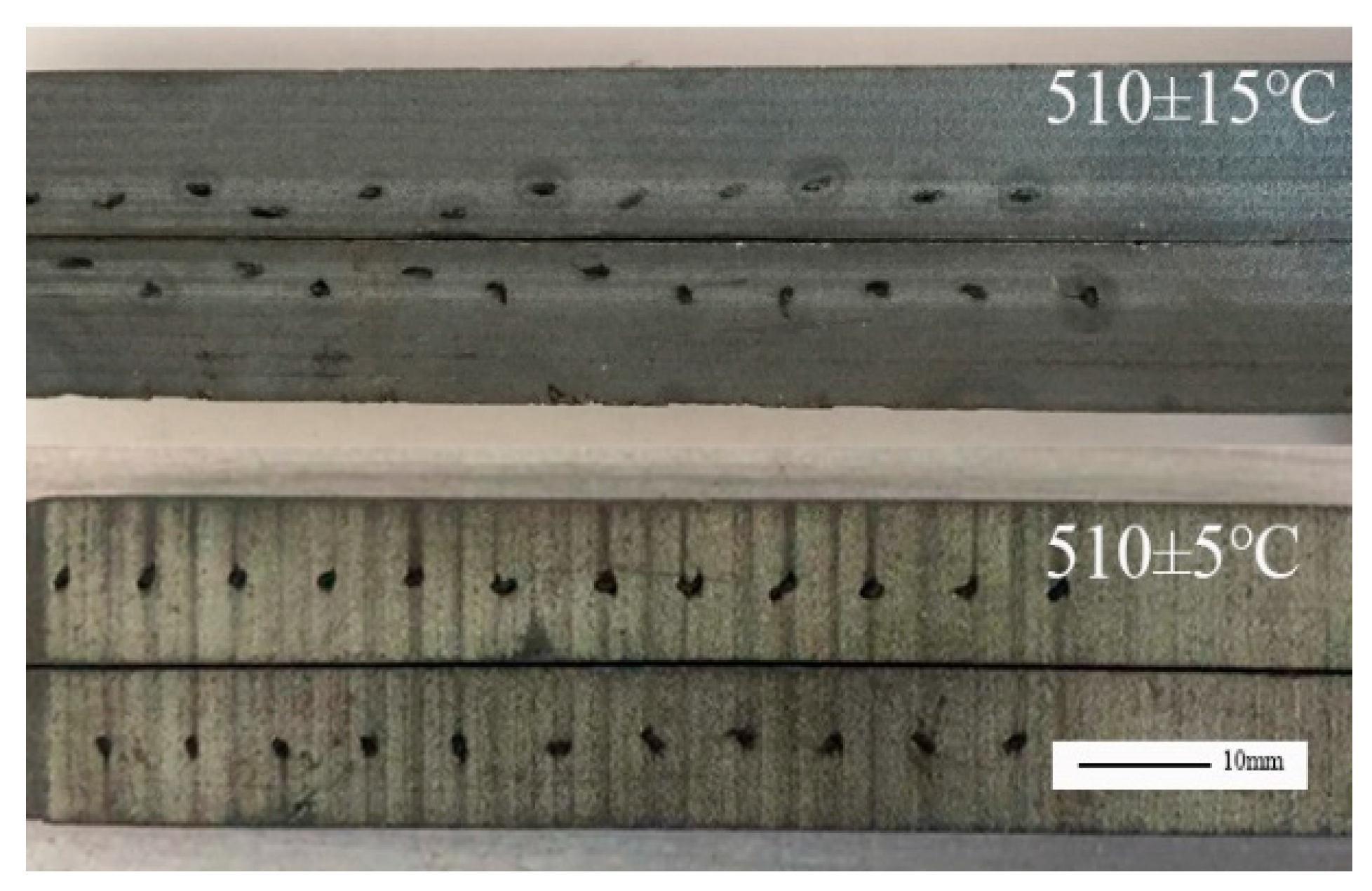
In the continuous casting process, the change of melt temperature causes the height fluctuation of the liquid-solid interface in crystallizer. When the change range of the melt temperature is larger, the fluctuation of the liquid-solid interface change is larger. During the periodic increase and decrease of the melt temperature, the helical radius of the helical carbon fibers in the lead matrix changes periodically. When the range of the melt temperature is 510±15℃, the helical radius of the helical carbon fiber has a relatively large fluctuation. When the melt change range is reduced to 510±5℃, the helical radius of the helical carbon fiber is relatively uniform, such as shown in
Figure 9.
4.2. Influence of Process Parameters on the Shape of Helical Carbon Fiber in Lead Matrix
4.2.1. Melting Temperature
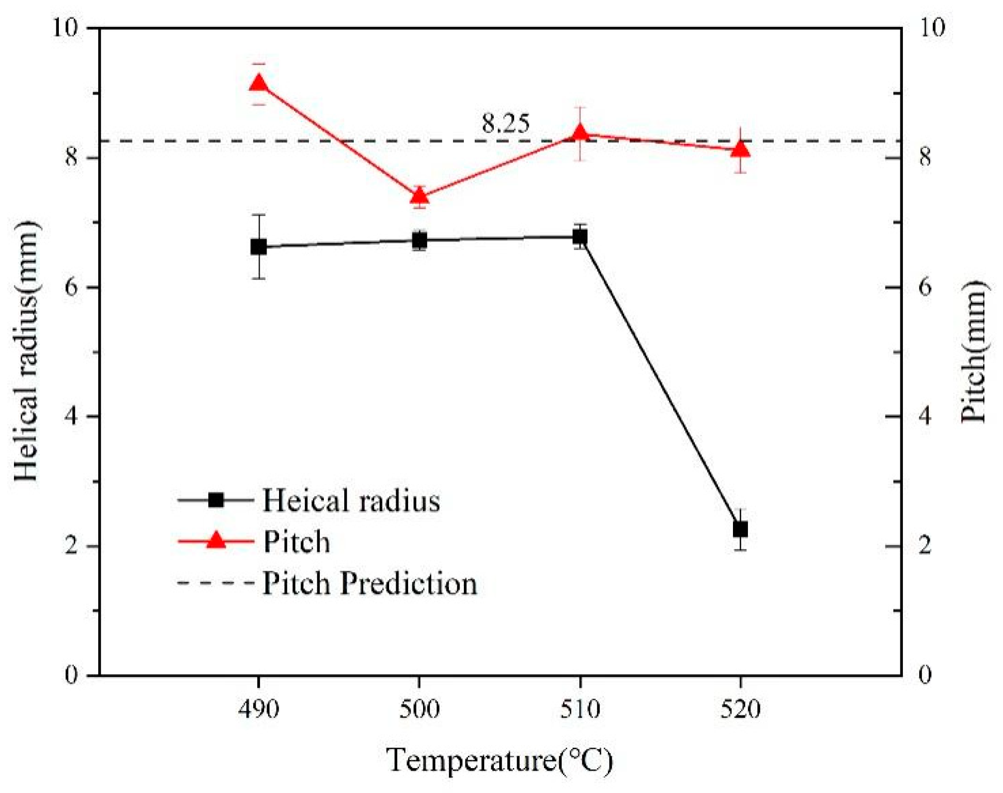
The effect of melt temperature (from 490 to 520 °C) on the helical carbon fiber shape (helix radius and pitch) in lead matrix composites, as shown in
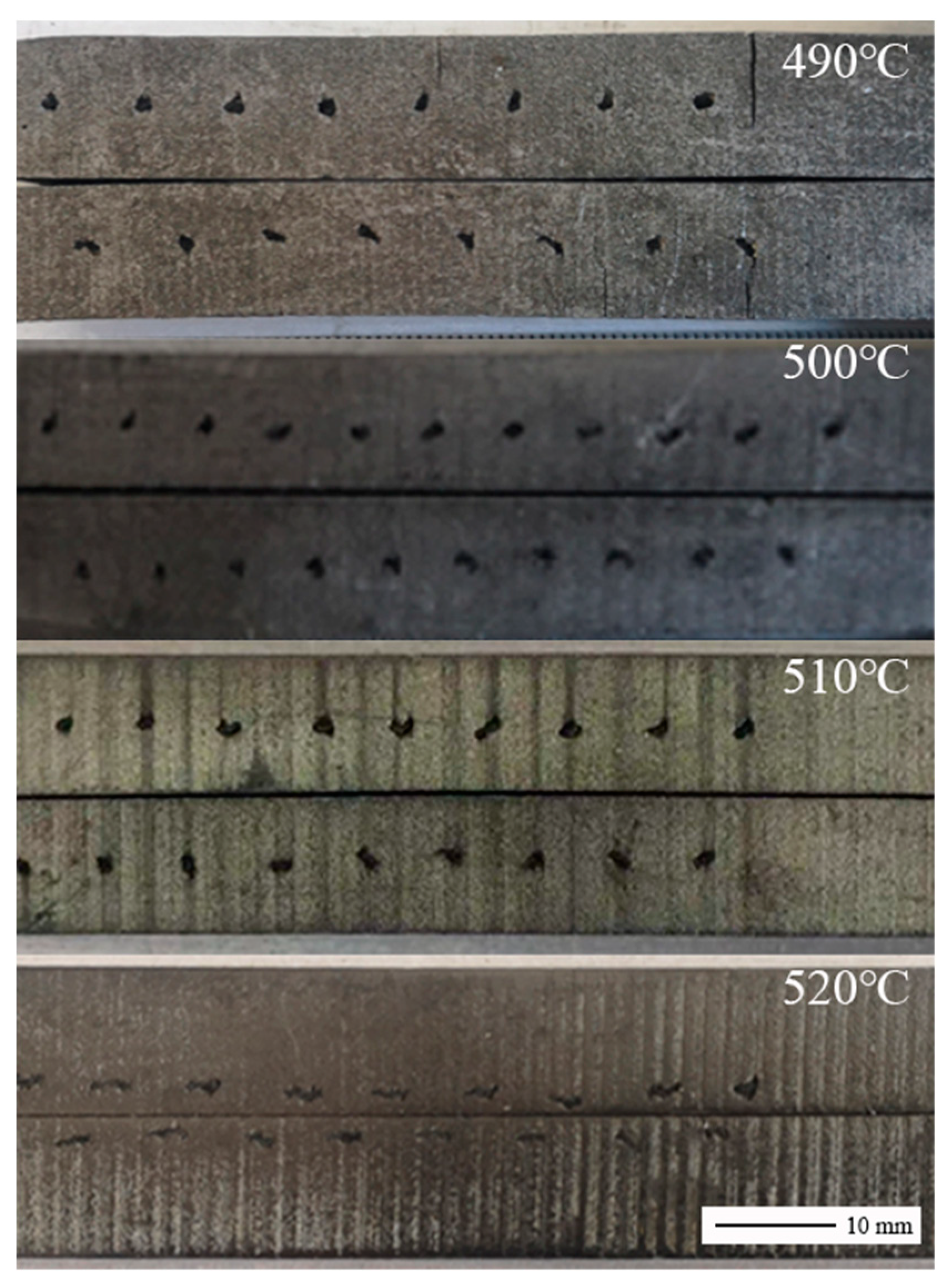
Figure 10. When the melt temperature was increased from 490 to 520°C, the helical radius of carbon fiber in the lead matrix showed a downward trend. However, when melt temperature is in range of 490 to 510 °C, the change of the helix radius is not obvious. When the melt temperature rises to 520°C, the helical radius decreases significantly, as shown in
Figure 11. The pitch is basically the same as the predicted value of the process model, and the difference is mainly caused by measurement errors. Since the liquid-solid interface height needs to be measured experimentally, the predicted value of the helical radius is not given in the figure.
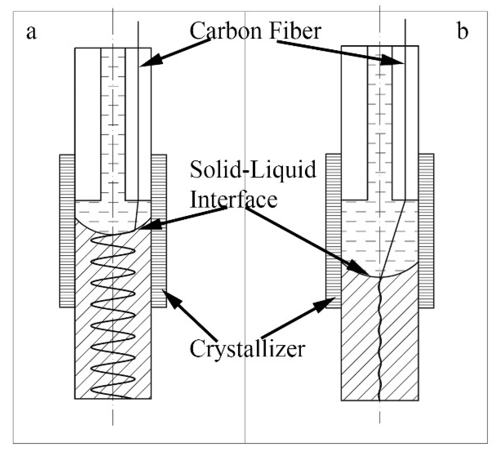
When the melt temperature is low, the height of the solid-liquid interface
h is low. According to the Equation (8),the helix radius of the helical carbon fiber formed in the lead matrix is larger than that of the high melt temperature .While the pitch of the helical carbon fiber is only related to the rotation speed of the fiber and the continuous casting speed, so it does not change with the temperature ,as shown in
Figure 12. In this experiment, when the melt temperature is 490-510℃, the height of the solid-liquid interface in the crystallizer does not change significantly with the temperature, so that the spiral radius of the spiral fiber does not change much. However, when the melt temperature reaches 520℃, the spiral radius decreases significantly, indicating that the solid-liquid interface decreases significantly. This phenomenon shows that the solid-liquid height is not linearly related to the melt temperature.
4.2.2. Cooling Intensity
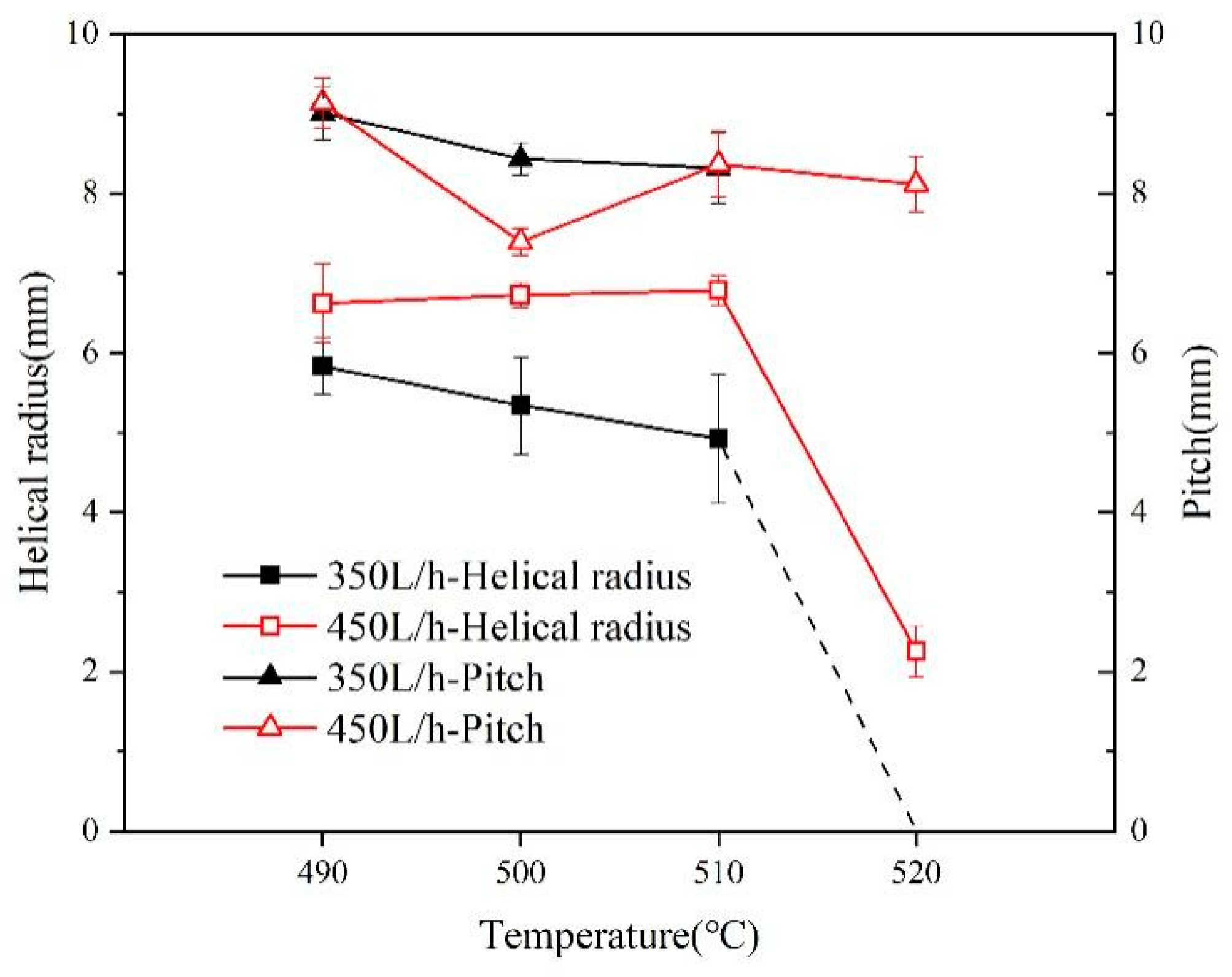
The effect of cooling intensity (from 350 to 450
) on the shape of helical carbon fibers (helix radius and pitch) in lead matrix composites, as shown in
Figure 13. At the same melt temperature, the helix radius increases with cooling intensity, the pitch basically does not change with the cooling intensity.
At the same melt temperature, the height of liquid-solid interface is increased with the cooling intensity, the process parameters h decreases, according to the Equation (8).the helix radius increases with its height. The pitch hardly changes with the cooling intensity. it is consistent with the process model.
4.2.3. Carbon Fiber Rotation Speed
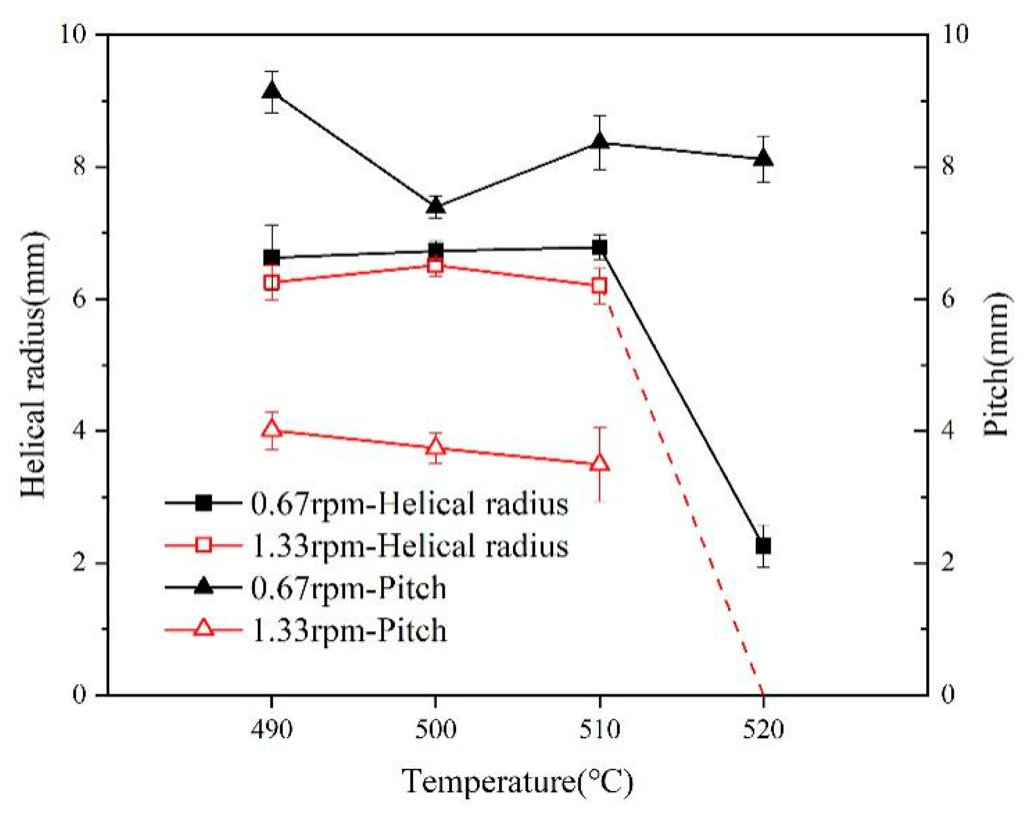
The effect of fiber rotation speed (from 0.67 to 1.33rpm) on the shape (helix radius and pitch) of carbon fibers reinforced lead matrix composites, as shown in
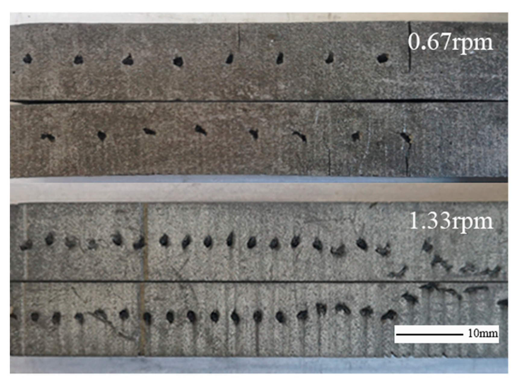
Figure 14. At the same melt temperature, the helical radius decreases with increasing fiber rotation speed. The pitch also decreases significantly with increasing fiber rotation speed, almost 1/2 of the former, as shown in
Figure 15. It is consistent with the proportional relationship between the fiber rotation speed and the pitch in the process parameters model.
According to the above model analysis, when the carbon fiber forms A stable helical shape on the lead base, the Angle difference between the addition point A of the carbon fiber and the helical formation point B will remain unchanged, as shown in
Figure 6 (j), that is, after one rotation of the carbon fiber, the helical fiber forms one cycle in the matrix. With the continuous casting speed constant, there is a linear relationship between the fiber rotation speed and the helical pitch, as shown in Equation (9).
4.3. Prediction of the Helical Fiber Shape
Since the pitch of the helical fibers is only related to the casting speed and the fiber rotation speed, the predicted value can be directly calculated. By taking the process parameters as the melt temperature of 490-520°C, the cooling intensity of 450L/h, the continuous casting speed of 5.5mm/min, the fiber rotation radius of 7.0mm, and the fiber rotation speed of 0.67rpm as the benchmark, the helical radius and pitch of helical carbon fibers in lead matrix were measured respectively,
The process parameter
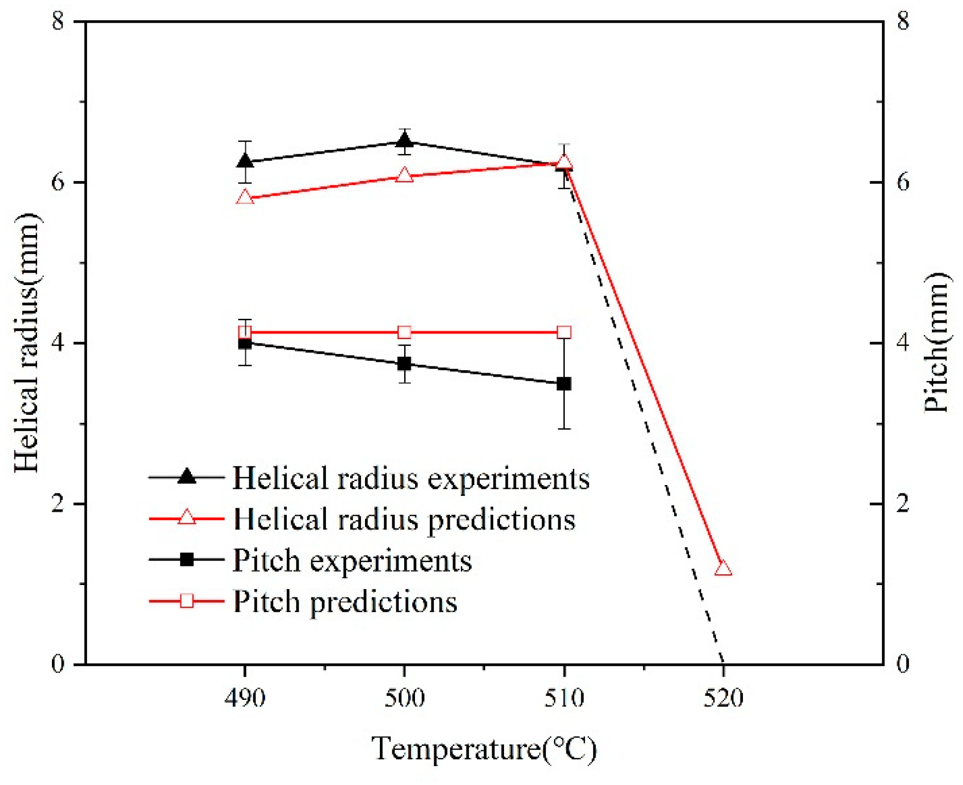
h can be Calculated at each temperature. When the fiber rotation speed increased to 1.33rpm, and substitute it into Equation (8) to obtain the predicted value of the helical radius at each temperature under the process conditions, compared with the experimentally measured value, as shown in
Figure 16. The deviation between the experimental value and the predicted value of the helical radius is at most 7.2%. Thus, the process model can accurately predict the helical shape of the helical carbon fiber of the composites through the process parameters.
4.4. Helical Carbon Fiber Reinforced Aluminum Matrix Composites
4.4.1. The Shape of Helical Carbon Fiber
According to the process in
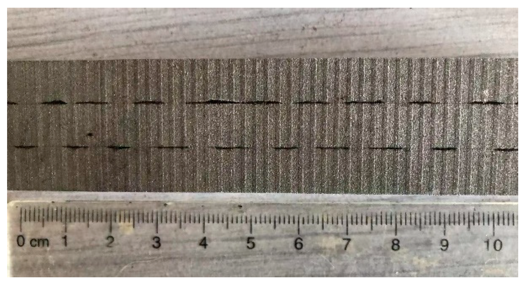
Table 1, the transverse section of the prepared helical carbon fiber reinforced aluminum matrix composites was shown in the
Figure 17. The radius of the helical carbon fiber is evenly distributed, and the helical pitch is relatively consistent.
4.4.2. Interface of Carbon Fiber and Aluminum Matrix
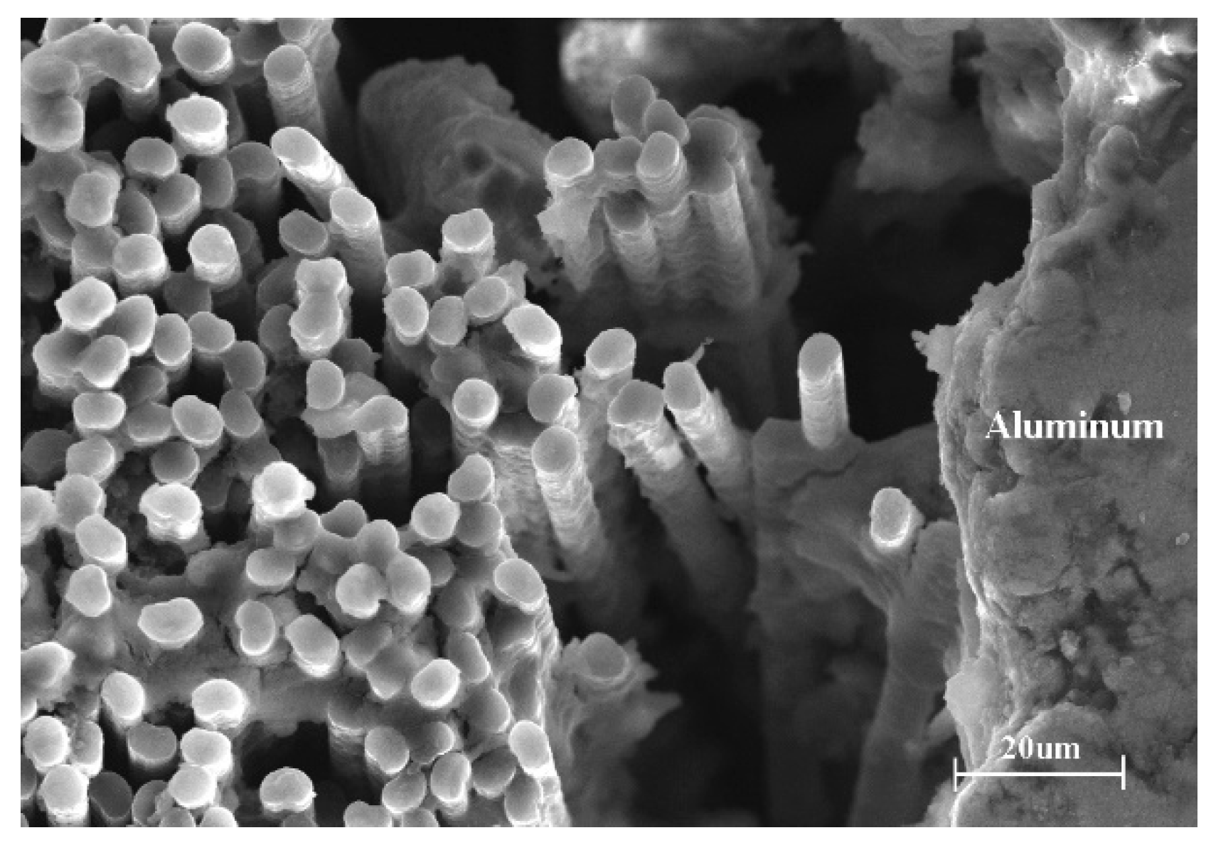
Figure 18 shows the SEM of the aluminum matrix and carbon fiber of the helical carbon fiber reinforced aluminum matrix composites. Through observation, it can be found that the carbon fiber bundle is not completely impregnated by the aluminum matrix, there are holes, and the carbon fiber is not fully combined with the aluminum matrix. it mainly because of the wettability between the carbon fiber and the molten aluminum is poor under normal pressure.
4.4.3. Mechanical Properties
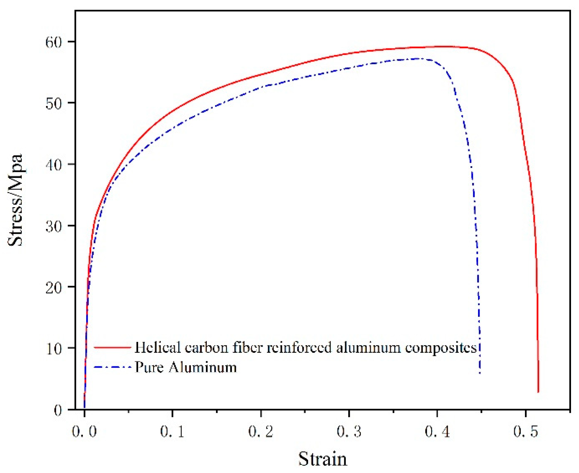
Figure 19 shows the stress-strain relationship between helical carbon fiber reinforced aluminum matrix composites and pure aluminum. It shows that the mechanical properties of the composites were better than that of pure aluminum, with higher tensile strength and elongation. However, due to the addition of only one helical carbon fiber bundle, the volume fraction of carbon fiber is low (about 1%), and the infiltration between carbon fiber and aluminum matrix is not complete, which reduces the improvement effect of helical carbon fiber on the properties of composites.
5. Conclusions
The continuous casting process of helical carbon fiber reinforced metal matrix composites was proposed, and the experimental equipment was designed to prepare helical carbon fiber reinforced lead/aluminum matrix composite:
1. The helical carbon fiber reinforced lead matrix composites were prepared by the novel process. The helical shape carbon fiber is distributed in the lead base stable and uniform.
2. The model between the shape parameter of helical fiber in metal matrix and the process parameters are described by differential geometry method. The helical carbon fiber reinforced lead matrix composites were prepared under different process conditions, the model.
3. The accuracy of the geometric model is verified by changing the process parameter (fiber rotation speed) that does not affect the height of the solid-liquid interface of continuous casting.
4. Helical carbon fiber shape uniformly distributed in the aluminum matrix. As the carbon fiber and the aluminum matrix was not completely combined and the volume fraction of carbon fiber is low, the mechanical properties of helical carbon fiber reinforced aluminum matrix composites have a small degree of enhancement.
Author Contributions
Conceptualization, Methodology, Validation, Formal Analysis, Investigation, Writing-Original Draft, Visualization. H.Y. Investigation, Resource. M.C. Methodology, Writing-review and Editing. C.W. All authors have read and agreed to the published version of the manuscript.
Funding
This research received no external funding.
Conflicts of Interest
The authors declare no conflict of interest.
References
- Wang, Y.; Wang, Z. Application of Aluminum Matrix Composites in Aircraft. Light Alloy Process. Technol. 2019, 47, 1–4. [Google Scholar]
- Zhang, Y.; Chen, G.; Xiu, Z.; et al. Space environment characteristics of carbon fiber reinforced aluminum matrix composites and their components. Hum. Spacefl. 2012, 18, 73–82. [Google Scholar]
- Kuan, F. Application of “Carbon Fiber Reinforced Composites” in Automobile Brake Pads. Gansu Metall. 2016, 38, 122–124. [Google Scholar]
- Liu, B. Modern cars and composites. High-Tech Fibers Appl. 2007, 32, 27–32. [Google Scholar]
- Li, Y. Application of Fiber Reinforced Aluminum Matrix Composites in Transmission Conductors. North China Power Technol. 2010, 29–32. [Google Scholar]
- Daoud, A. Microstructure and tensile properties of 2014 Al alloy reinforced with continuous carbon fibers manufactured by gas pressure infiltration. Mater. Sci. Eng. A 2005, 391, 114–120. [Google Scholar] [CrossRef]
- Li, S.; Chao, C. Effects of Carbon Fiber/Al Interface on Mechanical Properties of Carbon-Fiber-Reinforced Aluminum-Matrix Composites. Metall. Mater. Trans. A 2004, 35A, 2153–2160. [Google Scholar] [CrossRef]
- Yang, Q.; Liu, J.; Li, S.; et al. Fabrication and mechanical properties of Cu-coated woven carbon fibers reinforced aluminum alloy composite. Mater. Des. 2014, 57, 442–448. [Google Scholar] [CrossRef]
- Rohatgi, P.K.; Tiwari, V.; Gupta, N. Squeeze infiltration processing of nickel coated carbon fiber reinforced Al-2014 composite. J Mater Sci 2006, 41, 7232–7239. [Google Scholar] [CrossRef]
- Meyers, M.A.; Chen, P.; Lin, A.Y.; et al. Biological materials: Structure and mechanical properties. Prog. Mater. Sci. 2008, 53, 1–206. [Google Scholar] [CrossRef]
- Ji, B.; Gao, H. Mechanical principles of biological nanocomposites. Annu. Rev. Mater. Res. 2010, 40, 77–100. [Google Scholar] [CrossRef]
- Shao, Y.; Zhao, H.P.; Feng, X.Q.; Gao, H. Discontinuous crack-bridging model for fracture toughness analysis of nacre. J. Mech. Phys. Solids 2012, 60, 1400–1419. [Google Scholar] [CrossRef]
- Grason, G.M. Braided bundles and compact coils: The structure and thermodynamics of hexagonally packed chiral filament assemblies. Phys. Rev. E 2009, 79, 1–15. [Google Scholar] [CrossRef] [PubMed]
- Li, L.; Weaver, J.C.; Ortiz, C. Hierarchical structural design for fracture resistance in the shell of the pteropod Clio pyramidata. Nat. Commun. 2015, 6, 6216. [Google Scholar] [CrossRef]
- Li, S.; Fu, S.; Zhou, B.; et al. Bamboo—A natural biocomposite research. J. Mater. Res. 1994, 8, 188–192. [Google Scholar]
- Li, S.; Zhou, B.; Zhen, Z.; et al. A biomimetic composite model at the mesoscale. Adv. Mater. Sci. 1991, 5, 543–547. [Google Scholar]
- Zhao, Z.; Li, B.; Feng, X. Handedness-dependent hyperelasticity of biological soft fibers with multilayered helical structures. Int. J. Non-Linear Mech. 2016, 81, 19–29. [Google Scholar] [CrossRef]
- Reese, S.P.; Maas, S.A.; Weiss, J.A. Micromechanical models of helical superstructures in ligament and tendon fibers predict large Poisson’s ratios. J. Biomech. 2010, 43, 1394–1400. [Google Scholar] [CrossRef]
- Slepyan, L.I.; Krylov, V.I.; Parnes, R. Helical inclusion in an elastic matrix. J. Mech. Phys. Solids 2000, 48, 827–865. [Google Scholar] [CrossRef]
- Gao, Y.; Li, B.; Wang, J.; Feng, X.-Q. Fracture toughness analysis of helical fiber-reinforced biocomposites. J. Mech. Phys. Solids 2020, 146, 104206. [Google Scholar] [CrossRef]
- Wang, L.; Cui, Y.; Qin, Q.; et al. Helical Fiber Pull-out in Biological Materials. Acta Mech. Solida Sin. 2016, 29, 243–255. [Google Scholar] [CrossRef]
- Wang, L.; Yuan, L.; Wang, L.; et al. Numerical Study on Helical Fiber Fragmentation in Chiral Biological Materials. Trans. Tianjin Univ. 2018, 24, 51–58. [Google Scholar] [CrossRef]
- Li, S.; Zhang, R.; Fu, S.; et al. A Biomimetic Model of Fiber-reinforced Composite Materials. J Mater Sci Technol 1994, 10, 34–38. [Google Scholar]
- Li, S.; Fu, S.; Zhou, B.; et al. Experimental investigation of biomimetic double-helical reinforcing elements. J. Mater. Sci. Lett. 1995, 14, 769–772. [Google Scholar] [CrossRef]
- Kagawa, Y.; Nakata, E.; Yoshida, S. Fracture Toughness of Helical Fiber Reinforced Cu/W Composites. J Japan Inst Metals 1983, 47, 760–767. [Google Scholar] [CrossRef]
- Chang, X.; Xu, Q.; Lv, J.; Xu, L.; Zhu, Z.; Liu, S.; Liu, X.; Qin, J. Bioinspired 3D helical fibers toughened thermosetting composites. Composites Part B 2021, 216, 1–10. [Google Scholar] [CrossRef]
- Liang, J.; Wu, C.; Zhao, Z.; Tang, W. Forming Process and Simulation Analysis of Helical Carbon Fiber Reinforced Aluminum Matrix Composite. Metals 2021, 11, 2024. [Google Scholar] [CrossRef]
- Deshpandea, M.; Gondila, R.; Waikar, R.; et al. Processing and Characterization of Carbon Fiber Reinforced Aluminium7075. Mater. Today Proc. 2018, 5, 7115–7122. [Google Scholar] [CrossRef]
- Lalet, G.; Kurita, H.; Heintz, J.; et al. Thermal expansion coefficient and thermal fatigue of discontinuous carbon fiber-reinforced copper and aluminum matrix composites without interfacial chemical bond. J mater Sci 2014, 49, 397–402. [Google Scholar] [CrossRef]
- Xiong, J.; Zhang, H.; Peng, Y.; et al. Fabrication and Characterization of Plasma-Sprayed Carbon-Fiber-Reinforced Aluminum Composites. J Therm Spray Tech 2018, 27, 727–735. [Google Scholar] [CrossRef]
Figure 1.
(a)The schematic of helical carbon fiber reinforced metal matrix composites. (b) The plastic deformation of composites under axial load.
Figure 1.
(a)The schematic of helical carbon fiber reinforced metal matrix composites. (b) The plastic deformation of composites under axial load.
Figure 2.
(a) Continuous casting equipment of preparing the helical fiber reinforced metal matrix composites, (b) Fiber rotation device and its schematic.
Figure 2.
(a) Continuous casting equipment of preparing the helical fiber reinforced metal matrix composites, (b) Fiber rotation device and its schematic.
Figure 3.
Process parameters of HFCC.
Figure 3.
Process parameters of HFCC.
Figure 4.
Helical carbon fiber reinforced lead matrix composites samples.
Figure 4.
Helical carbon fiber reinforced lead matrix composites samples.
Figure 5.
3D space cartesian coordinate system O-xyz.
Figure 5.
3D space cartesian coordinate system O-xyz.
Figure 6.
Geometric state of liquid metal in the crystallizer of fibers during the preparation process, speed change, top view.
Figure 6.
Geometric state of liquid metal in the crystallizer of fibers during the preparation process, speed change, top view.
Figure 7.
The fiber shape at Stable state (a) unfolded the helical fibers in metal matrix (b).
Figure 7.
The fiber shape at Stable state (a) unfolded the helical fibers in metal matrix (b).
Figure 8.
Schematic of the unfolding of the fiber helical shape.
Figure 8.
Schematic of the unfolding of the fiber helical shape.
Figure 9.
Influence of melt temperature range on the stability of helical carbon fiber shape in lead matrix.
Figure 9.
Influence of melt temperature range on the stability of helical carbon fiber shape in lead matrix.
Figure 10.
Influence of melt temperature on the shape of helical carbon fiber in the lead matrix()
Figure 10.
Influence of melt temperature on the shape of helical carbon fiber in the lead matrix()
Figure 11.
Helical shape of carbon fiber in lead matrix at different melt temperatures()
Figure 11.
Helical shape of carbon fiber in lead matrix at different melt temperatures()
Figure 12.
The height of solid-Liquid Interface at different melt temperature. (a) low melt temperature;(b) high melt temperature
Figure 12.
The height of solid-Liquid Interface at different melt temperature. (a) low melt temperature;(b) high melt temperature
Figure 13.
Influence of cooling intensity on the shape of helical carbon fiber in lead matrix (The dotted line indicates that the helical shape of carbon fiber has not formed,)
Figure 13.
Influence of cooling intensity on the shape of helical carbon fiber in lead matrix (The dotted line indicates that the helical shape of carbon fiber has not formed,)
Figure 14.
Influence of carbon fiber rotation speed on the shape of helical carbon fiber in lead matrix (The dotted line indicates that the helical shape of carbon fiber has not formed, )
Figure 14.
Influence of carbon fiber rotation speed on the shape of helical carbon fiber in lead matrix (The dotted line indicates that the helical shape of carbon fiber has not formed, )
Figure 15.
Helical shape of carbon fiber in lead matrix at different fiber rotation speed ()
Figure 15.
Helical shape of carbon fiber in lead matrix at different fiber rotation speed ()
Figure 16.
Comparison between the shape of helical carbon fiber in lead matrix experimental and model predictions (The dotted line indicates that the helical shape of carbon fiber has not formed,)
Figure 16.
Comparison between the shape of helical carbon fiber in lead matrix experimental and model predictions (The dotted line indicates that the helical shape of carbon fiber has not formed,)
Figure 17.
Helical carbon fiber reinforced aluminum matrix composites
Figure 17.
Helical carbon fiber reinforced aluminum matrix composites
Figure 18.
SEM images of aluminum matrix and carbon fiber of spiral carbon fiber reinforced aluminum matrix composite.
Figure 18.
SEM images of aluminum matrix and carbon fiber of spiral carbon fiber reinforced aluminum matrix composite.
Figure 19.
Stress-strain relationship between helical carbon fiber reinforced aluminum matrix composite and pure aluminum
Figure 19.
Stress-strain relationship between helical carbon fiber reinforced aluminum matrix composite and pure aluminum
Table 1.
Continuous casting process parameters of helical carbon fiber reinforced metal matrix composites.
Table 1.
Continuous casting process parameters of helical carbon fiber reinforced metal matrix composites.
| Parameters |
Range |
| Lead matrix |
Aluminum matrix |
|
0.67, 1.33 |
0.67 |
|
7.0 |
7.0 |
|
490, 500, 510, 520 |
780 |
|
350, 450 |
450 |
|
5.5 |
5.5 |
|
Disclaimer/Publisher’s Note: The statements, opinions and data contained in all publications are solely those of the individual author(s) and contributor(s) and not of MDPI and/or the editor(s). MDPI and/or the editor(s) disclaim responsibility for any injury to people or property resulting from any ideas, methods, instructions or products referred to in the content. |
© 2024 by the authors. Licensee MDPI, Basel, Switzerland. This article is an open access article distributed under the terms and conditions of the Creative Commons Attribution (CC BY) license (http://creativecommons.org/licenses/by/4.0/).
