Preprint
Article

Reliability Optimization Design of Constrained Metamorphic Mechanism Based on the Augmented Assur Groups

Altmetrics

Downloads

74

Views

14

Comments

0

A peer-reviewed article of this preprint also exists.

This version is not peer-reviewed

Submitted:

22 June 2024

Posted:

24 June 2024

You are already at the latest version

Alerts
Abstract
In order to obtain stable and reliable configuration transformation ability, reliability optimization design is regarded as an effective way to reduce the probability of kinematic function failure for the constrained metamorphic mechanism. Based on the structural composition principle of multi-configuration source metamorphic mechanism that can operate in an under-actuated state, the modularized calculation methods are established for the force analysis of augmented Assur groups including metamorphic kinematic joints. According to the equivalent resistance gradient model of metamorphic mechanisms, with considering the uncertainties in the link dimensions, masses, and compliance parameters et al, a probabilistic evaluation method for describing the configuration transformation ability of the constrained metamorphic mechanism is established. Based on reliability evaluation and reliability sensitivity analysis, a reliability optimization design method for improving the configuration transformation ability is proposed, and then the optimization design is carried out for tolerances of random variables focusing on those structural parameters with higher reliability sensitivity, so that the optimized results can satisfy the requirements of both reliability and economic simultaneously. Finally, the feasibility and effectiveness of the proposed method is verified by the illustration of a paper folding metamorphic mechanism. The research provides the foundation of reliability design of metamorphic mechanisms to obtain the high-probability repeated execution ability of configuration transformation, it also has theoretical and practical significance to promote the engineering application of metamorphic mechanisms.
Keywords: 
Subject: Engineering  -   Mechanical Engineering

1. Introduction

At the 25th ASME Annual Conference on Mechanism and Robotics in 1998, DAI et al. [1] first proposed the concept of metamorphic mechanisms. The mechanism has the ability of self-reconfiguration according to different task requirements and working conditions, which has attracted significant interest all over the world. JIN et al. [2] established a dynamic analysis model of the metamorphic mechanism by using the Kane equation. DAI et al. [3] systematically expounded the principle of mesomorph and a general categorization of metamorphic mechanisms. GUO et al. [4] studied the topological analysis of variable mobility mechanisms by applying the metamorphic principles. LAN et al. [5] put forward a new adjacency matrix to describe the topological changes of metamorphic mechanisms, which can not only preserve the information of the original mechanism but also derive all possible changes of the mechanism. LI et al. [6,7] presented the structure composition principle of single-driven metamorphic mechanisms based on augmented Assur groups, and then defined a non-dimension equivalent resistance coefficient of metamorphic joints and an equivalent resistance gradient model of metamorphic mechanisms. KANNER et al. [8] studied the influence of variations in design parameters on the passive adaptability of underactuated robot legs to uneven terrain and discussed the stability of the robot with respect to their postures. COPPOLA et al. [9] proposed a methodology named re-configurable dynamics to reconfigure the kinematics and dynamics parameters. WANG et al. [10] established a nonlinear dynamic model of a novel metamorphic palletizing robot to describe all the configurations under actual operating when its configuration changed from 1-DOF to 2-DOF. YANG et al. [11] studied the type synthesis of constrained metamorphic mechanisms with structural forms of metamorphic joints. LI et al. [12] first proposed a new method for analyzing the constraint force of metamorphic kinematic joints, which provided the basis for dynamic analysis of metamorphic mechanisms. WANG et al. [13] carried out static analysis of an underactuated manipulator, analyzed its grasping stability and optimized its structural parameters. AIMEDEE and GOGU et al. [14] addressed metamorphic and re-configurable mechanisms based on types of morphing and ways of achieving it considering various types of morphing, mainly including topological morphing [15,16], geometrical morphing [17,18] and furcating morphing [19,20], etc. TIAN et al. [21] introduced a method for configuration synthesis of metamorphic mechanisms on the basis of five metamorphic modes: the geometry, motion, force, driving joint and combined metamorphic mode. QIAO et al. [22] calculated the general static contact force of a 3-DOF underactuated robotic finger using the principle of virtual work, analyzed its self-adaptive grasp process and equilibrium configuration. SONG et al. [23] built a unified dynamics model of constrained metamorphic mechanisms. Based on the model, the kinematic laws of all components, the driving force/torque of the driving link and the constraint force/torque of the metamorphic joints can be obtained. YANG et al. [24] proposed a general structural design method for a planar metamorphic mechanisms based on the structural synthesis matrix. WANG and KONG et al. [25] established a full-configuration kinematic reliability model of a planar five-bar metamorphic mechanism considering multi-source uncertainties such as joint clearances, manufacturing tolerances of links, thermal deformations of links and joints.
Reliability optimization design is one of the important branches of reliability design. There are mainly two ideas about how to optimize: (1) Maximize reliability of the mechanism when it meets the requirements of performance and/or cost; (2) Minimize factors of the mechanism such as cost, volume and weight, under the condition of meeting the reliability requirements. With the development of computer technology and programming, more and more advanced optimization algorithms are applied to reliability optimization. LIAO et al. [26] employed genetic algorithm to complete the error optimization of a new 6-DOF parallel mechanism, which provided foundation for the research on tolerance optimization. PAN [27,28] used self-adaptive genetic algorithm and fuzzy genetic algorithm to optimize the cost-tolerance model of a 6-DOF parallel robot. CHEN et al. [29,30] analyzed the kinematics performance of 4-UPS-RPU parallel mechanism, and optimized its structure parameters based on the global dexterity coefficient. NI et al. [31] transformed the design of tolerances into a nonlinear optimization design with constraints based on sensitivity analysis, and applied genetic algorithm to distribute the manufacturing tolerances of a parallel machine tool finally. XIONG [32] applied fuzzy theory to the multi-objective optimization design of a double-stage wheel hub reducer system taking the minimum volume and maximum reliability as the objective function.
DAI and KANG [33] pointed out that: “ It is of great significance for the innovation and development of advanced manufacturing technology and a new generation of robots to study intelligent reconfigurable mechanisms and robots with the ability to actively adapt to changing environments and working conditions and passively adapt to emergencies.” The ability of convenient variable-working configuration/variable-topological structure is an important performance of metamorphic mechanism. The precise transforming of adjacent configurations and the maintenance of each working configuration are the basis for metamorphic mechanism to complete the operational tasks. For constrained metamorphic mechanisms, the transforming/maintenance of working configurations is mainly realized by the transforming/maintenance of the moving and static of the metamorphic kinematic joints (variable kinematic joints). Therefore, some specific “switching” structures of metamorphic joints need to be designed for realizing the transformation between moving and static. The inborn attribute of metamorphic joint determines that the failure of configuration transformation is the most frequent failure mode for the constrained metamorphic mechanism in completing operational tasks, and the ability of completing configuration transformation precisely is a crucial indicator for performance of the metamorphic mechanisms. At present, some researchers [34] have point out that: “It has always been an unsolved problem to switch their motion patterns smoothly and reliably for multi-mode mechanisms/multiconfiguration mechanisms.” Obviously, the reliability-based optimization design focusing on the stability of configuration transformation is the basis of improving the stability and reliability of configuration transformation. Currently, only a few researchers studied the probabilistic failure on kinematic performance of metamorphic mechanisms by applying reliability-based optimization design. WANG et al. [35] proposed of reliability evaluation and optimization design based on variable state space to study the kinematic reliability of metamorphic mechanisms with multiple failure modes. At present, few literatures are introduced about systematically research on the probability evaluation and the reliability-based optimization design of configuration transformation ability based on the force analysis during the kinematic status switch of metamorphic joints at the moment of configuration transforming. The remainder of the paper is organized as follows: Section 2 introduces the working process and structure composition principle of constrained metamorphic mechanisms. Section 3 proposes modularized force analysis methods of constrained metamorphic mechanisms first, and then completes the structural design for a novel metamorphic revolute joint according to force analysis. Section 4 establishes the evaluation model of configuration transformation ability of constrained metamorphic mechanism under deterministic parameters, and then presents a probabilistic evaluation model of configuration transformation ability by considering the randomness of input errors in practical application. Section 5 proposes a reliability-based optimization design method of constrained metamorphic mechanisms oriented to the stability of configuration transformation. In Section 6, the proposed method of reliability optimization design is illustrated by an example of the paper folding metamorphic mechanism to verify its feasibility and effectiveness. Finally, Section 7 concludes the paper.

2. General Metamorphic Working Process and Structure Composition Principle of Constrained Metamorphic Mechanisms

2.1. General Working Process of Constrained Metamorphic Mechanisms

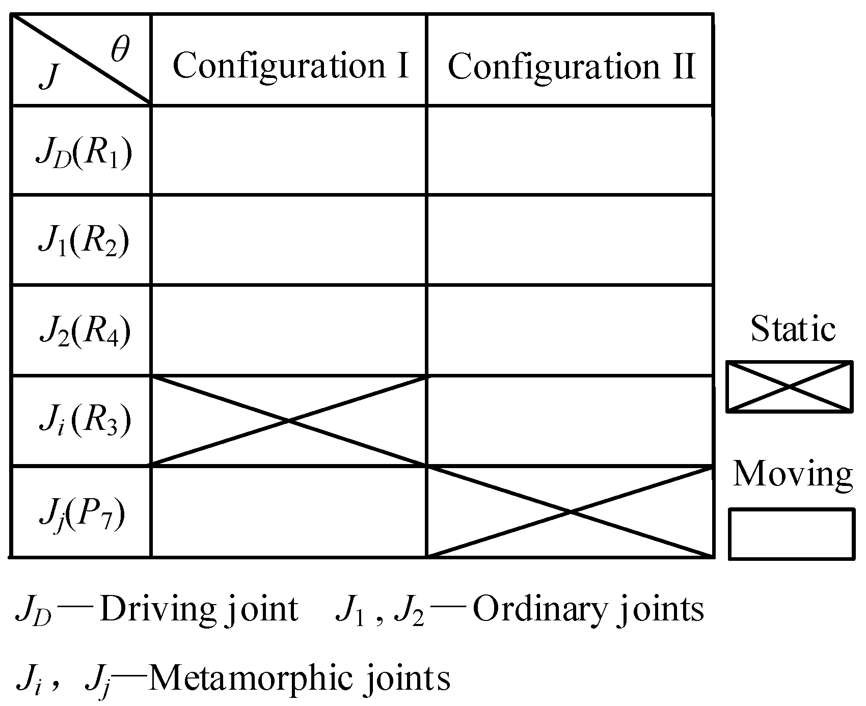
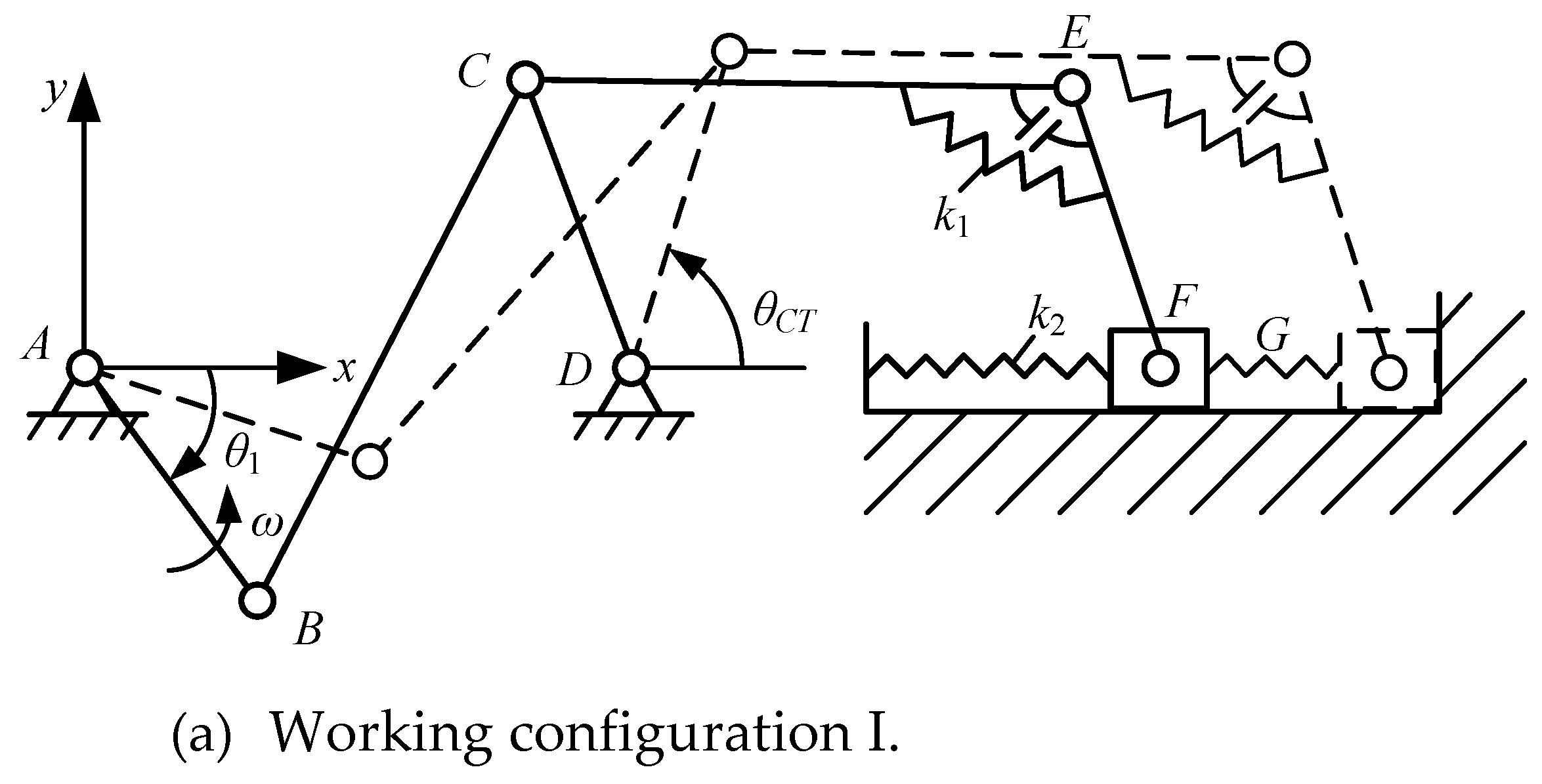
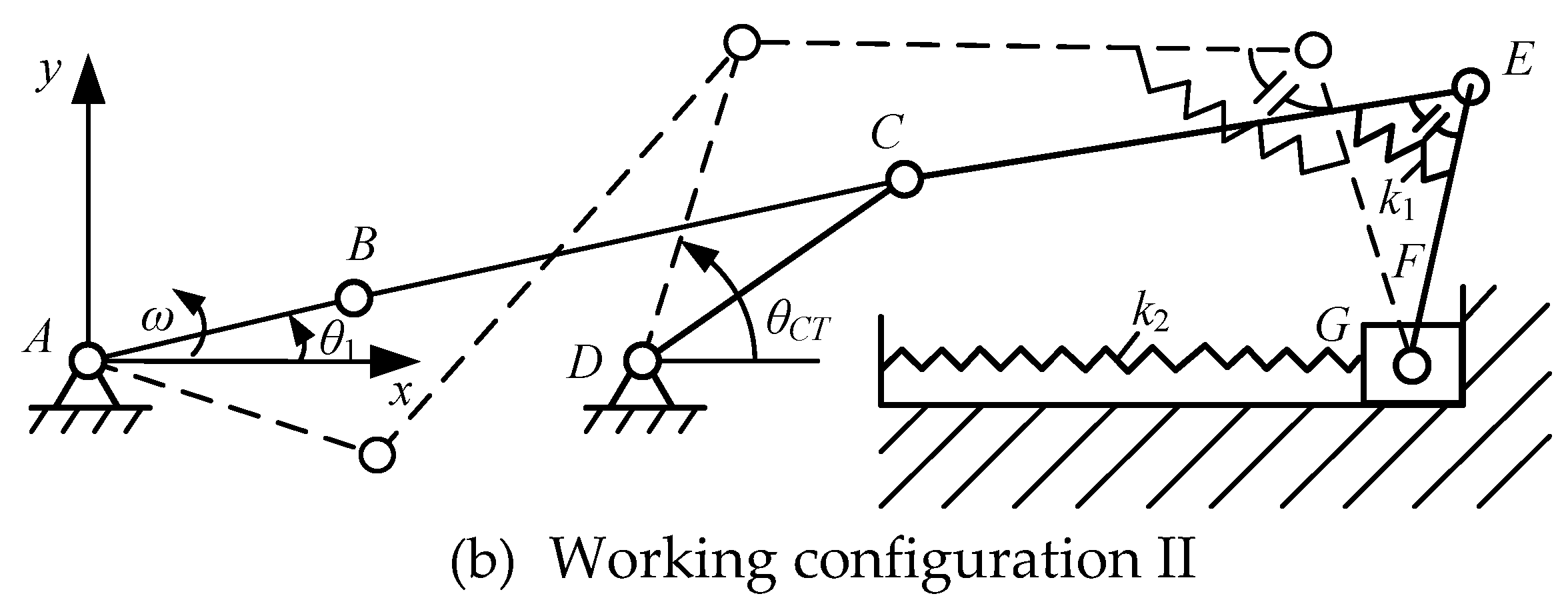
A general metamorphic working process of the constrained metamorphic mechanism is as following: by transforming the moving/static kinematic status of metamorphic joints based on geometric constraints and/or force constraints provided by the specific structures of the links and joints, the multi-DOF source metamorphic mechanism is degenerated into a single-DOF metamorphic mechanism to form the corresponding working stages and keep the working configuration of the mechanism for completing the desired operational task. Then, by releasing the constrained metamorphic joint and constraining other metamorphic joints, the working configuration is transformed and another working stage is formed. Another operational task is accomplished by keeping the working configuration. The working sequences of required working stages are controlled by constraining different metamorphic joint in the sequences. To obtain all the working configurations of metamorphic mechanism, all the metamorphic kinematic joints should be constrained alternately according to the required working stages and working sequences. Figure 1 is a 2-DOF constrained metamorphic mechanism with a single driver, and Figure 2 is the metamorphic cyclogram of the mechanism which describes the change of kinematic status of kinematic joints with different configurations. As can be seen from Figure 1 and Figure 2, the constrained metamorphic mechanism in Figure 1 realizes two working configurations/topological structures of crank-slider mechanism and crank-rocker mechanism by using the kinematic status transformations of metamorphic joints R3 with combined constraints of spring force and geometric constraints and P7 with geometric constraints as shown in Figure 2 (R represents revolute joint and P represents prismatic joint), and then completes the corresponding operational tasks in their respective working configurations.

2.2. Structure Composition Principle of Constrained Metamorphic Mechanisms

According to the structure composition theory of traditional mechanisms [36], any planar mechanisms can be formed by means of adding several elements of the Assur groups (AGs) to the driver link and the frame and/or the former element of the AGs and the frame [37,38]. The class II Assur group are widely applied in the planar mechanisms, which are divided into five different elements. If an additional binary link and a revolute joint or prismatic joint are added into any element of the five class II AG, The DoF of the new element in the augmented groups is one instead of zero in the class II AG, and the augmented groups are named the class II Augmented Assur groups (AAGs) [7], which have nine different forms as shown in Figure 3.
In order to obtain a n-DOF constrained metamorphic mechanism operated by a single actuator, a convenient way is to make n−1 metamorphic joints static to eliminate (n−1)-DOF during every working stage. According to the idea, a structure composition principle of the n-DOF source mechanism based on the augmented Assur groups can be described as follow.
n-DOF source mechanism = (1-DOF driver) + (n − 1) × (1-DOF group) +
x (0-DOF group)
As shown in Eq. (1), x represents an arbitrary integer which is equal to or greater than zero. Based on 1-DOF augmented Assur groups summarized in Figure 3, n−1 of these 1-DOF AAGs and any 0-DOF AGs are connected to the 1-DOF driving link, frame, or ahead AAGs/AGs in sequence, which compose one of the n-DOF source mechanisms shown in Eq. (1). Therefore, the 2-DOF constrained metamorphic mechanism as shown in Figure 1 can be regarded as a 1-DOF augmented Assur group (RRRP shown in Figure 3(d)) connected to the driving link and the frame in sequence.
For an n-DOF source mechanism, according to the structure composition principle described in Eq. (1) and Figure 1, n metamorphic joints must be arranged into it to obtain n working configurations. For the n metamorphic joints of the n-DOF source mechanism in the case of one driving link, only one metamorphic joint keeps moving in each working stage while the others remain static. Therefore, in order to realize all working configurations, every metamorphic joint must be constrained in sequence according to the required working stages according to Figure 2. Obviously, the kinematic status of the metamorphic joint depends on the driving force/torque and constraint force/torque acted on it.

3. Modularized Force Analysis of Constrained Metamorphic Mechanisms and Structural Design of Metamorphic Revolute Joints

According to structure composition principle of constrained metamorphic mechanisms based on augmented Assur groups, taking the driving link, AGs and AAGs as the basic units, the mathematical relationships between the kinematic or force analysis of each unit are deduced. In the paper, kinematic and force analysis of AAGs can be completed on the basis of the general kinematic and force analysis approach of the class II AGs.
Since every metamorphic joint must be constrained in sequence according to the required working stages, take one AAG as an example, one of the metamorphic joints can be constrained in the corresponding configuration of the metamorphic process, and the AAG can degenerate into the corresponding equivalent AG. Therefore, the kinematic and force analysis of the AAG can be carried out in different working configurations, and which are equal to the analyses of the corresponding equivalent Assur group in each working configuration. Since the kinematic analysis method of the augmented Assur group [39] is nearly the same as that of the corresponding Assur group, the paper builds the calculation model of force analysis of the augmented Assur group containing metamorphic joints based on the general force analysis of the Assur group. Because modularized force analysis of the nine elements of augmented Assur groups is similar to each other, the AAG RRRP included in the metamorphic mechanism shown in Figure 1 is taken as an example to illustrate the procedure of analysis.
In different working configurations, the equivalent Assur group of the AAG RRRP is shown in Figure 4, where the revolute joint 2 and the prismatic joint 4 are metamorphic joints. In the working configuration I, link 1 and link 2 are annexed into a united one because metamorphic revolute joint 2 is constrained to keep static, and metamorphic prismatic joint 4 moves simultaneously, so the AAG RRRP degenerates into the RRP group. In the working configuration II, the metamorphic prismatic joint 4 is constrained to transform from moving to static, the metamorphic revolute joint 2 changes from static to moving, so the AAG RRRP degenerates into the RRR group. The derivation process of modularized force analysis of the AAG RRRP is given as follows.

3.1. Modularized Force Analysis of AGGs

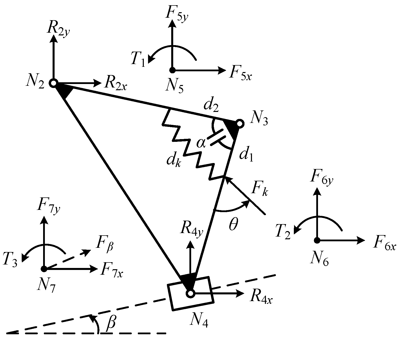
In the working configuration I, the AAG RRRP degenerates into the Assur group RRP. The force analysis of the corresponding equivalent Assur group RRP is shown in Figure 5, where points N5, N6 and N7 are the centroids of the links N2N3, N3N4 and the slider respectively, and Fβ is the component of the external force acting on the slide along the moving direction. Supposing that the external forces F5, F6, F7 and torques T1, T2 , T3 acted on the links N2N3, N3N4 and the slider respectively are known, the reaction force of each revolute joint and the driving torque and constraint torque of the metamorphic revolute joint are solved.
Modularized force analysis procedures are as follows:
cos α = l 23 2 + l 34 2 l 24 2 2 l 23 l 34 = d 1 2 + d 2 2 d k 2 2 d 1 d 2
d k = d 1 2 + d 2 2 d 1 d 2 ( l 23 2 + l 34 2 l 24 2 ) l 23 l 34
F k = k ( a d k )
cos θ = d k 2 + d 1 2 d 2 2 2 d k d 1
θ = arccos [ 2 d 1 2 d 1 d 2 ( l 23 2 + l 34 2 l 24 2 ) l 23 l 34 2 d 1 2 + d 2 2 d 1 d 2 ( l 23 2 + l 34 2 l 24 2 ) l 23 l 34 d 1 ]
T k = F k d 1 sin θ
{ R 2 x = ( A 1 sin β + B 1 P 24 x ) P 24 x cos β + P 24 y sin β R 2 y = ( A 1 cos β + B 1 P 24 y ) P 24 x cos β + P 24 y sin β A 1 = ( T 54 + T 64 + T 1 + T 2 ) B 1 = ( F 5 x + F 6 x + F 7 x ) cos β ( F 5 y + F 6 y + F 7 y ) sin β
{ R 4 x = ( R 2 x + F 5 x + F 6 x ) R 4 y = ( R 2 y + F 5 y + F 6 y )
F β = F 7 x cos β + F 7 y sin β
In the above equations, k denotes the spring stiffness, a denotes the original length of the spring, Pijx and Pijy denote the distance in x and y directions respectively, Rix and Riy denote the reaction forces of joint i in the x and y directions respectively, Fix and Fiy denote the forces acting on point i in x and y directions respectively, Tij denotes the torque of the force acting on point i to point j, Ti denotes the torque acting on point i, and Tk denotes the torque of spring force to point N3.
Supposing that the counterclockwise direction is positive, T53 and T63 denote the torque of the gravities of the two links N2N3 and N3N4 to point N3 respectively, Δ T denotes the driving torque of the metamorphic revolute joint:
{ T 23 = P 23 x R 2 y P 23 y R 2 x T 43 = P 43 x R 4 y P 43 y R 4 x T 53 = P 53 x m 23 g T 63 = P 63 x m 43 g
Δ T = T 23 T 43 + T 53 T 63
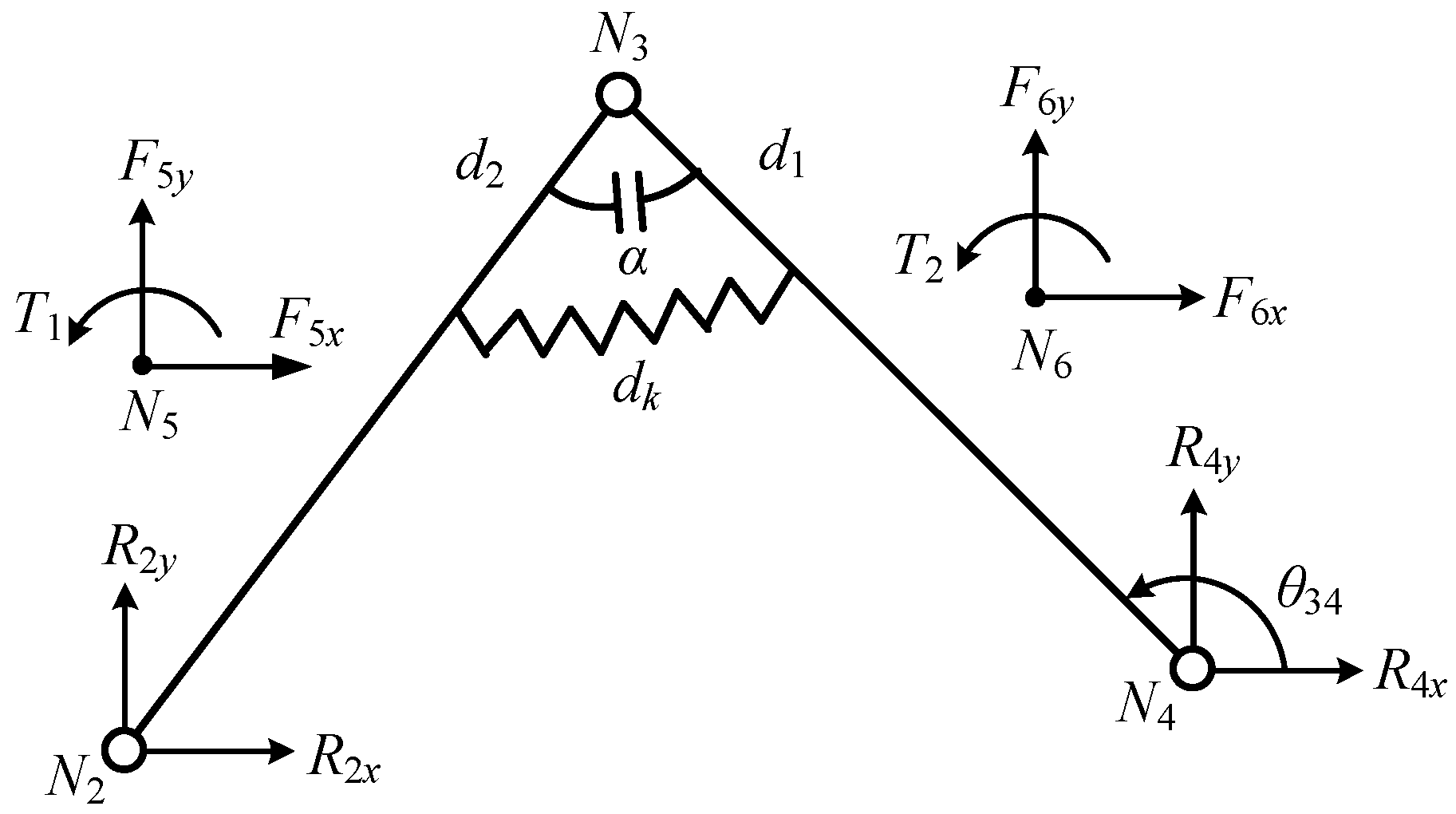
In the working configuration II, the AAG RRRP degenerates into the RRR group. The force analysis of the corresponding equivalent Assur group RRR is shown in Figure 6, where points N5 and N6 are the centroids of the links N2N3 and N3N4 respectively. Given forces F5, F6 and torques T1, T2 act on the links N2N3 and N3N4 respectively. Solve the reaction force of each revolute joint and the driving torque and constraint torque of the metamorphic revolute joint. According to the above conditions, the reaction force of each revolute joint and the driving torque and constraint torque of the metamorphic revolute joint are solved.
Modularized force analysis procedures are as follows:
{ R 4 x = ( A 2 P 43 x B 2 P 42 x ) P 43 x P 42 y P 43 y P 42 x R 4 y = ( A 2 P 43 y B 2 P 42 x ) P 43 x P 42 y P 43 y P 42 x A 2 = ( T 51 + T 61 + T 1 + T 2 ) B 2 = ( T 63 + T 2 + T k )
{ R 2 x = ( R 4 x + F 5 x + F 6 x ) R 2 y = ( R 4 y + F 5 y + F 6 y )
{ R 3 x = ( R 4 x + F 6 x + F k x ) R 3 y = ( R 4 y + F 6 y + F k y ) F k x = F k cos ( θ 34 + θ π ) F k y = F k sin ( θ 34 + θ π )
In the above equations, Fkx and Fky denote the components of the spring force in x and y directions respectively. The calculation method of the variables dk, θ, Fk, Tk, Δ T and the meaning of the other variables can refer to the force analysis in the working configuration I above.

3.2. Structure Design of Metamorphic Revolute Joint according to Constraint Parameters Calculated in Modularized Force Analysis

When the metamorphic revolute joint keeps static in a working configuration, the angle of its two links must be constrained, neither increasing nor decreasing. The common way to keep static is to use spring force constraints and/or geometric constraints in the structure design of metamorphic joints. In previous studies, metamorphic joints are often drawn in kinematic diagrams without structure design. For practical application, a simple and practical structure of the metamorphic revolute joint is designed in the paper as shown in Figure 7(a), and the physical prototype is shown in Figure 7(c).
The link (1), the end cover (3) and the component (6) are connected as a united one as shown in Figure 7(b). The link (2) and the component (4) are connected as a united one by bolts. The balls at both ends of the component (6) can move along the grooves which are located on the internal surface of the component (4), so that the two links (1) and (2) can rotate relative to each other. As shown in Figure 7(a), the pin (5) serves as an actual geometric constraint, and the angle of the metamorphic revolute joint can’t increase after the component (6) contacts the pin (5). The spring is compressed with a preload and installs on the links. When the driving torque of the metamorphic revolute joint is large enough to overcome the force of compressed spring, link (2) rotates clockwise relative to link (1) due to the release of both geometrical constraint and spring force constraint.
At the limiting position, geometric constraints of the metamorphic revolute joints theoretically provide infinite constrained force to ensure that the angle can’t increase. At the same time, if the metamorphic revolute joint plans to keep static in a working configuration, the constraint torque provided by the spring force from preload should be greater than the maximum value of driving torque during the entire process of configuration keeping to limit the reduction of the angle between link (1) and (2), that is as follow:
F k Δ T d 1 sin θ
Fk is the spring force from preload, d1 and θ are the corresponding structural dimensions as shown in Figure 5. Furthermore, we can design the structural parameters of spring by using the range of spring preload calculated by Eq. (16).

4. Probabilistic Evaluation Model for the Configuration Transformation Ability of Constrained Metamorphic Mechanisms

4.1. Evaluation of Configuration Transformation Ability Based on Equivalent Resistance Gradient Model

In order to enable the constrained metamorphic mechanism to accurately complete the configuration transforming and realize the desired movements, the types and constraint architectures of metamorphic joints should be determined. Moreover, the constraint forces of the corresponding metamorphic joints should be calculated. Therefore, the equivalent resistance gradient model is established in Ref. [8]. First, a dimensionless coefficient f e ( θ i ) is defined:
f e m ( θ i ) = | F c ( θ i ) F min | = | T c ( θ i ) T min |
f e s ( θ i ) = | F c ( θ i ) F max | = | T c ( θ i ) T max |
f e m ( θ i ) is the equivalent resistance coefficient of moving metamorphic joint in the working stages, f e s ( θ i ) is the equivalent resistance coefficient of static metamorphic joint in the working stages. Fmin and Tmin are the minimum driving force and torque acted on moving metamorphic joint in the corresponding working stages. Fmax and Tmax are the maximum driving force and torque acted on static metamorphic joint in the corresponding working stages.
The moving sequences of metamorphic joints should be proportional to the equivalent resistant forces coefficient according to the law of minimum resistance of kinematics. Therefore, the equivalent resistance gradient of the metamorphic joints in the working stages of constrained metamorphic process should be as follow:
f e s ( θ i ) 1  和  f e m ( θ i ) 1
Taking the constrained metamorphic mechanism shown in Figure 1 as an example, the force analysis method of the RRRP augmented Assur group can be referred to in Section 3.1. According to Eqs. (17)-(19), the equivalent resistance coefficients of metamorphic joints R3 and P7 must meet the following conditions in the two configurations:
In the working configuration I, the metamorphic revolute joint R3 should always keep static and the metamorphic prismatic joint P7 should always keep moving to ensure the desired working sequence. The driving torque of joint R3 is provided by Δ T in the Eq. (12), and the constraint torque is provided by the spring force constraint and geometric constraint together. When Δ T < 0 , the angle of the metamorphic revolute joint R3 tends to increase, but keeps unchanged due to geometric constraint. When Δ T > 0 , the angle of joint R3 tends to decrease and the spring is compressed. In order to make joint R3 still keep static during the working configuration I, the constraint torque provided by the spring should be always greater than the driving torque:
f e 3 = F k d 1 sin θ Δ T 1
The beginning of the working configuration II is regarded as the moment of configuration transforming. At the moment, the metamorphic prismatic joint P7 begins to switch from moving to static because of geometric constraint, and the metamorphic revolute joint R3 begins to change from static to moving. Since the geometric constraint force is theoretically infinite, it is obvious that the probability of the metamorphic prismatic joint P7 to finish the configuration transformation is nearly 100%. In order to complete the switch from static to moving of metamorphic revolute joint R3 accurately at the moment of configuration transforming, the driving torque at the moment should be greater than the constraint torque of the spring force:
f e 3 ' = F k d 1 sin θ Δ T < 1
In the working configuration II, the metamorphic prismatic joint P7 should always keep static and the metamorphic revolute joint R3 should always keep moving to ensure the desired working sequence. Since the slider is under geometric constraints, the constraint force is theoretically infinite, so the slider can never move to the right. At the same time, in order to ensure that the slider can not move to the left, the component of the reaction force on the slider along the moving direction should be always to the right and greater than the leftward component of the external force along the moving direction of the slider:
f e 7 = R 4 x cos β + R 4 y sin β | F β | 1
The calculation formulas of R4x and R4y are shown in Eq. (13), Fβ is the component of the external force on the slider along the moving direction as shown in Figure 5, as shown in Eq. (10), and β is the angle between the moving direction and the horizontal axis.

4.2. Random analysis of Configuration Transformation of Constrained Metamorphic Mechanisms

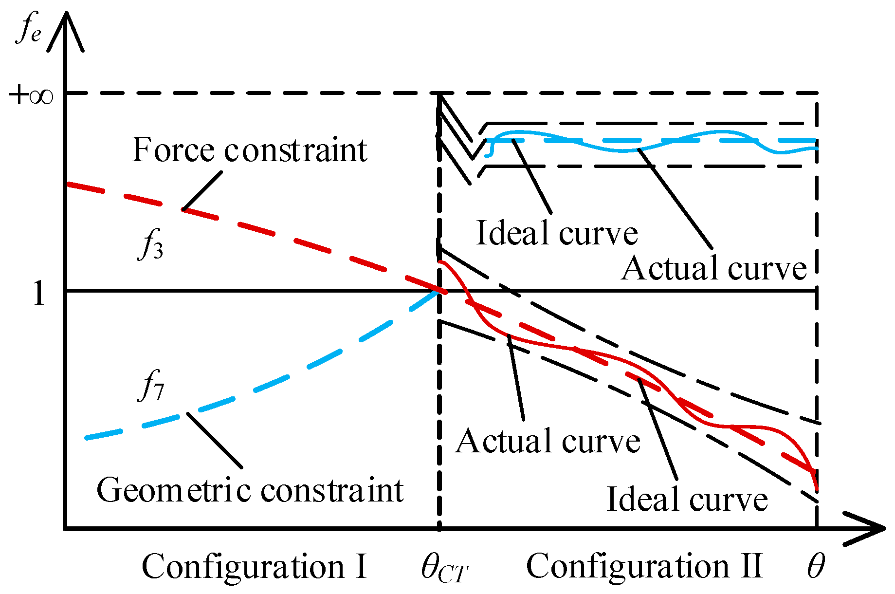
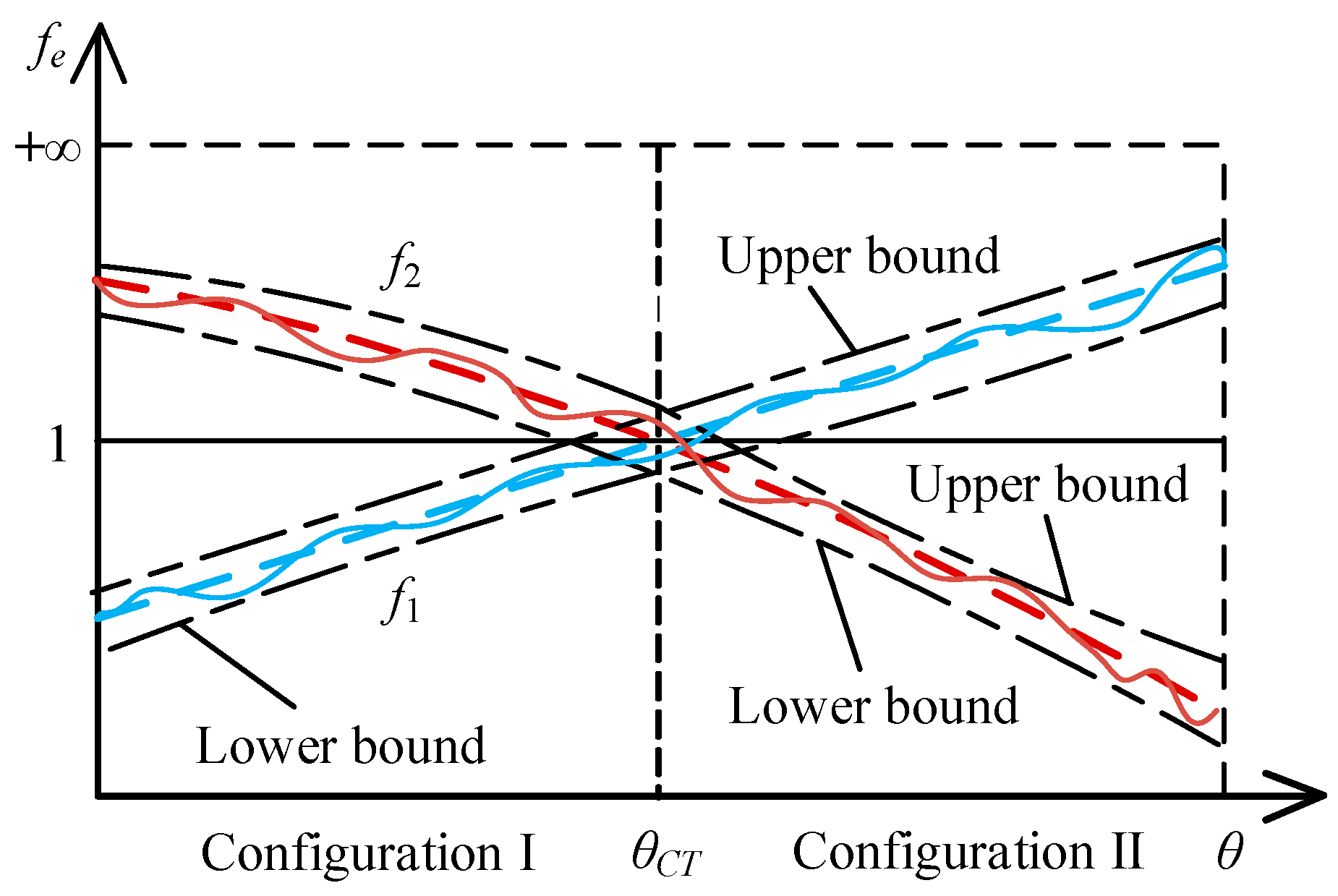
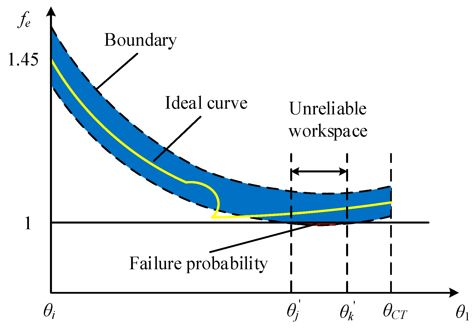
In practical application, there are a lot of uncertain factors, such as the uncertainties of link dimensions, clearances of joints and fit errors caused by manufacturing tolerances, masses and moment of inertia, spring stiffness, size and installation errors in metamorphic joints with spring force constraints, the driving errors of actuators, time-varying performance degradation typically represented by the increase of clearances of joints caused by wear et al. The factors can lead to the fact that the driving force and constrained force of any metamorphic joints in metamorphic mechanisms produced according to the same blueprint are not determined values, but random variables with some certain distributions. For the reason above, the actual equivalent resistance coefficients of the metamorphic joints are also random variables. Figure 8 shows the ideal equivalent resistance coefficient curves of the metamorphic joints R3 and P7 of the mechanism shown in Figure 1 and two of the actual curves randomly selected when errors are considered in configuration II. From the Figure 8, It can be seen that the actual equivalent resistance coefficients f3 and f7 fluctuate randomly in their envelope of confidence region. According to the equivalent resistance gradient model, the equivalent resistance coefficient f e = 1 is the boundary value between moving and static of the metamorphic joints. When it is near to the moment of configuration transformation, the equivalent resistance coefficient of metamorphic joint of force constrained is closer to 1 (Figure 8). Therefore, the fluctuation of its value is more likely to cause the failure of the kinematic status transformation of metamorphic joints, and then result in the failure of configuration transforming of constrained metamorphic mechanisms. Obviously, the analysis above also confirms the conclusion that the failure of configuration transformation is the most likely failure model of constrained metamorphic mechanism from the perspective of force analysis. Figure 9 shows the equivalent resistance coefficient curves of two metamorphic joints with spring force constraints. Due to the random fluctuation of the two equivalent resistance coefficients at the moment θCT, the probability of successful configuration transforming of constrained metamorphic mechanisms with the spring force constraints is usually lower than that of the mechanism with a geometric constraint and a spring force constraint shown in Figure 8. Obviously, compared with the deterministic model, it is more practical engineering significance that how to define and solve the probability of successful configuration transforming.

4.3. Reliability Evaluation Model of Configuration Transformation Ability

Given the randomness of the driving force F and the resistance Fc of a metamorphic joint k, when the kinematic status of the metamorphic joint changes from static to moving at the moment of configuration transformation, the reliability of kinematic status transformation is as follows:
R k = P ( f e < 1 ) = P ( F > F c ) = - f s ( x s ) [ - x s f 1 ( x 1 ) d x 1 ] d x s
When the metamorphic joint switches from moving to static at the moment of configuration transformation, the reliability is as follow:
R k = P ( f e > 1 ) = P ( F < F c ) = - f s ( x s ) [ x s f 1 ( x 1 ) d x 1 ] d x s
f s ( x s ) is the probability density function of the driving force, and f 1 ( x 1 ) is the probability density function of the resistance force.
Obviously, the configuration transformation of the metamorphic mechanism is mainly realized by switching the motion state of metamorphic joints. Therefore, the probability of the successful transformation moment of the constrained metamorphic mechanism with n working configurations at a single configuration transforming is defined as the product of the probabilities Rk of the successful kinematic status transformations of n metamorphic joints. The joints participate in configuration transformation of constrained metamorphic mechanisms:
R c = Π i = 1 n R k i = P ( f e 1 ( θ C T ) < 1 ) Π i = 2 n P ( f e i ( θ C T ) > 1 )
θCT is the position angle of driving link at the moment of configuration transformation.
According to the equivalent resistance gradient curves shown in Figure 8 and Figure 9, the equivalent resistance coefficient is close to 1 at the adjacent moments of the configuration transforming. At the moment, the fluctuation of equivalent resistance coefficient is more likely to cause the undesired working sequence. Therefore, it is necessary to give the interval reliability calculation model of the configuration transforming.
Planar metamorphic joints are divided into metamorphic revolute joints and metamorphic prismatic joints, and both of them exit in augmented Assur group RRRP as shown in Figure 3. Therefore, taking the constrained metamorphic mechanism (Figure 1) with the RRRP augmented Assur group as an example, the interval reliability calculation model of the configuration transforming is established , which can provide reference to analyze the configuration transforming reliability of constrained metamorphic mechanisms containing other augmented Assur groups. Moreover, the force analysis method of RRRP augmented Assurgroup can refer to Section 3.1. Some factors need to be considered, such as the uncertainties in the link dimensions, masses, angular velocity and angular displacement of driving link, spring stiffness, installation position of spring and constrained angular of geometric constraint. Meanwhile, it is assumed that all the uncertainty parameters are random variables, and each of them is expressed by an independent and normal, i.e., Gaussian distribution.
As described in Section 4.1, whether the mechanism shown in Figure 1 can work well in the working configuration I is mainly determined by whether the metamorphic revolute joint R3 can keep static all the time.
Take Eqs. (8), (9), (11) into Eq (12) respectively to calculate the driving torque of metamorphic revolute joint R3:
Δ T 1   = T 23 T 43 + T 53 T 63 = P 23 x R 2 y P 23 y R 2 x P 43 x R 4 y + P 43 y R 4 x + P 53 x m 23 g P 63 x m 34 g = f ( l 12 , l 23 , l 34 , α , m 23 , m 34 , m s l i d e r , ω 1 , θ 1 )
Bring Eqs. (4), (6) into Eq (7) respectively to calculate the resistance torque of metamorphic revolute joint R3:
T k = F k d 1 sin θ = k ( a d k ) d 1 sin θ = f ( k , d 1 , d 2 , α )
Therefore, the limit state function of the ability to keep static of the metamorphic revolute joint R3 in the working configuration I is expressed as follow:
Z 1 = T k Δ T 1
At the moment of configuration transforming, the metamorphic prismatic joint P7 begins to switch from moving to static, and the metamorphic revolute joint R3 changes from static to moving. Since the geometric constraint force is theoretically infinite, the probability of joint P7 to complete the configuration transformation is regarded nearly to 1. Therefore, whether the mechanism shown in Figure 1 can complete configuration transformation at the
moment is mainly determined by whether joint R3 can switch form static to moving accurately.
Take Eqs. (11), (13), (14) into Eq (12) respectively to obtain the driving torque of joint R3 at the moment of configuration transformation:
Δ T C T = T 23 T 43 + T 53 T 63 = P 23 x R 2 y P 23 y R 2 x P 43 x R 4 y + P 43 y R 4 x + P 53 x m 23 g P 63 x m 34 g = f ( l 12 , l 23 , l 34 , k , d 1 , d 2 , α , m 23 , m 34 , ω 1 , θ 1 )
The spring is not compressed at the moment of configuration transformation. Consequently, the consistent torque of joint R3 keep constant as Eq. (27). Therefore, the limit state function of the kinematic status transformation ability of joint R3 at the moment of configuration transformation is expressed as Eq. (30) similarly:
Z C T = Δ T C T T k
In order to ensure the desired working sequence in the working configuration II, joint P7 should always keep static. To keep joint P7 static, the slider requires sufficient driving force. In other words, the resultant force of the reaction force and the external force along the guide path is always to the right.
The component of the reaction force on the slider along the moving direction is as follow:
R β = R 4 x cos β + R 4 y sin β = f ( l 12 , l 23 , l 34 , k , d 1 , d 2 , m 23 , m 34 , ω 1 , θ 1 )
The calculation formula of R4x and R4y is shown in Eq. (13).
The component along the moving direction of the external force Fβ acted on the slider is shown in Eq. (10).
In most cases, the direction of the reaction force on the slider is to the right and the direction of the external force is to the left. Therefore, the limit state function of the ability to keep static of joint P7 in the working configuration II can be expressed as follow:
Z 2 = R β F β
By applying the method of First Order Second Moment, the first-order Taylor expressions of the limit state function of the above three working stages are expanded, and the error models of the limit state function are established. Taking the moment of configuration transforming as an example, the mean μ T 1 and variance σ T 1 2 are calculated respectively:
μ Z C T = f ( μ l 12 , μ l 23 , μ l 34 , μ k , μ d 1 , μ d 2 , μ α , μ m 23 , μ m 34 , μ ω 1 , μ θ 1 )
σ Z C T 2 = ( f l 12 ) 2 σ l 12 2 + ( f l 23 ) 2 σ l 23 2 + ( f l 34 ) 2 σ l 34 2 + ( f α ) 2 σ k 2 + ( f m 23 ) 2 σ d 1 2 + ( f m 34 ) 2 σ d 2 2 + ( f α ) 2 σ α 2 + ( f m 23 ) 2 σ m 23 2 + ( f m 34 ) 2 σ m 34 2 + ( f ω 1 ) 2 σ ω 1 2 + ( f θ 1 ) 2 σ θ 1 2
Since the limit state functions of the three working stages of the constrained metamorphic mechanism (Figure 1) are known, and both the driving torque and the resistance torque accord with normal distribution. By applying the stress strength interference model [33], the reliability of configuration transforming/keeping ability of constrained metamorphic mechanisms is as follow:
R = P ( Z > 0 ) = 0 f ( Z ) d Z = 0 1 2 π σ Z exp [ 1 2 ( Z μ Z σ Z ) 2 ] d Z
Eq. (36) is obtained by converting Eq. (35) into standard normal distribution and sets z = Z μ Z σ Z
R = z 0 1 2 π exp [ 1 2 z 2 ] d z = 1 Φ ( z 0 ) = Φ ( β )
z 0 = μ Z σ Z ; β = μ Z σ Z
f ( Z ) is the limit state function whose mathematical expressions are Eqs. (28), (30) and (32) correspond to configuration I, configuration II and the moment of configuration transforming. Take the configuration transforming moment for example, the actual expression of the limit state function f ( Z C T ) could be solved by Eqs. (27), (29) and (30). Moreover, the partial derivative f x i for each input parameter xi (i=1, 2, 3, …, n) can be solved. Therefore, μ Z and σ Z could be obtained. Due to page limitations, we won’t go into details about the actual expression of f ( Z C T ) , μ Z and σ Z .
The constrained metamorphic mechanism is more likely to produce undesired working sequence at the adjacent moment of configuration transforming. Therefore, in the working configuration I and II of the equivalent resistance gradient curve, a and b adjacent moments of configuration transformation whose equivalent resistance coefficients close to 1 are respectively selected to calculate the reliability of the corresponding moments. Referring to the reliability calculation of the series system, multiply the reliabilities of (a+b) adjacent moments with the reliability Rc of the successful configuration transformation at the moment of configuration transforming. The interval evaluation method of reliability Rj for a single configuration transforming of the constrained metamorphic mechanism with two working configurations is as follow:
R j = Π i = 1 a R 1 i R c Π i = 1 b R 2 i
R1i is the reliability of the ith adjacent moment near configuration transforming in the working configuration I, and R2i is the reliability of the ith adjacent moment near configuration transforming in the working configuration II. Generally, the metamorphic mechanism with n working configurations needs to complete n-1 configuration transformations, so the global reliability of successful configuration transforming during all the metamorphic process of the constrained metamorphic mechanism with n working configurations is as follow:
R n = Π j = 1 n 1 R j
Rj is the reliability of a single configuration transforming, n is the number of working configurations.

5. Reliability Optimization Design Method Oriented to the Stability of Configuration Transformation

Reliability optimization design is an important part of reliability design, which means that under certain constraints, the best design scheme is given in accordance with the corresponding objective requirements. The general approach is to establish a mathematical model of design variables, objective functions and constraints for engineering problems, and then use intelligent optimization algorithms to calculate the optimal results. The general mathematical optimization model can be described as follow [41]:
{ min f ( d , X , Y ) s . t . Pr { g i ( d , X , Y ) 0 } [ R i ] i = 1 , 2 , n g d l < d < d u μ X l < μ X < μ X u
f ( d , X , Y ) is the objective function; d is the deterministic design variable; X is the random design variable vector, which is controlled by the designer during the design process; Y is the uncertainty design parameter, which is not controlled by the designer during the design process; Pr{•} is the probability of no failure; g i ( d , X , Y ) is the performance function related to the failure mode; ng is the number of performance functions; d l and d u are the lower and upper limits of d, μ X is the mean value of random design variable X, μ X l and μ X u are the lower and upper limits of μ X .

5.1. Determination of Optimization Design Parameters Based on Reliability Sensitivity Analysis

The discreteness of random variables of each structural parameter has different influence on the reliability of the configuration transformation of the metamorphic mechanism. If the variation of some structural parameter tolerance has a great influence on the reliability, it should be strictly controlled. Otherwise, the restrictions on them can be relaxed to reduce processing costs. Therefore, before the reliability optimization design of the configuration transformation ability of the metamorphic mechanism is carried out, the variance sensitivity of each structural parameter needs to be determined. Moreover, the random parameters whose tolerance values need to be strictly controlled should be determined, and the tolerance values should be selected as the optimization design variables.
The variance sensitivity [42] of the configuration transformation reliability of the constrained metamorphic mechanism to the structural parameter vector X = [ x 1 , x 2 , , x n ] T is as follow:
R V a r ( X ) = R β β σ Z σ Z V a r ( X )
It can be seen from Eqs. (35) and (36):
R β = φ ( β ) , β σ Z = μ Z σ Z 2 , σ Z V a r ( X ) = 1 2 σ z [ z ¯ X z ¯ X ]
Z is the limit state function. At the moment of working configuration I, configuration transformation and working configuration II, its expressions are Eqs. (28), (30) and (32). φ ( · ) is the probability density function of the standard normal distribution. V a r ( X ) represents the variance of the structural parameter vector. The symbol represents the Kronecker product, which is defined as ( A ) p × q ( B ) s × t = ( a i j B ) p s × q t .
Due to the inconsistency of units among the structural parameters that affect the reliability of the configuration transformation of the metamorphic mechanism, the reliability sensitivity of different parameters cannot be compared. Therefore, it is necessary to conduct dimensionless processing for reliability sensitivity [43]. After the dimensionless processing, the reliability to each variance sensitivity of structural parameters is as follow:
s x i = R V a r ( X ) σ x i 2 R
In order to analyze better the influence of the tolerance of each parameter on reliability, the variance sensitivity value is normalized to obtain the variance sensitivity coefficient S x i of each parameter:
S x i = | s x i s x i |
According to the calculation result of variance sensitivity coefficient of each parameter, tolerance of the parameter with higher sensitivity is taken as the optimization design variable.

5.2. Objective Function

The objective of optimization design is usually the lowest cost, lightest weight and highest stiffness. The objective function of the paper adopts a tolerance-cost model which can be constructed in many ways, such as exponential model, power exponential model, linear model and composite model. The commonly used power exponential model is selected by the paper, and the objective function established is as follows:
cos t ( x ) = i = 1 n k i ( c i ) α i
αi is the processing cost characteristic index [44] formulated according to the mechanical manufacturing process theory, generally αi = 0.7~1(αi = 0.7 is used in the paper). ki is the cost weight coefficient of the tolerance items of each parameter, and it is generally impossible to give an exact value in the optimization design stage. In the paper, combined with the analysis results of variance sensitivity, the variance sensitivity coefficient of each parameter is used as its cost weighting coefficient; n represents the number of optimization design variables.
Due to the different dimensions of each parameter in the optimization design, there are a large order of magnitude difference between each parameter. Therefore, the optimization result can be affected. In order to deal with the dimensionless calculation of the relative cost and optimize the variation coefficient ci of each parameter by the optimization model in the paper, cost(x) is a dimensionless parameter.

5.3. Constraint Condition

(1)Reliability constraints
The objective of the optimization design in the paper is to make the constrained metamorphic mechanism meet the given reliability index requirements of configuration transformation. The constraint condition is as follows:
R n [ R n ]
[Rn] is the allowable value of the preset reliability of configuration transformation.
(2)Single tolerance boundary condition
In the constraint conditions, the ranges of the coefficients of variation ci are respectively constrained. The constraint condition is as follows:
c i [ c i ]
[ci] (i = 1,2,…n) is the allowable value of the coefficient of variation of the corresponding parameter.

5.4. Reliability Optimization Design Based on Improved Genetic Algorithm

With the development of optimization theory and computer technology, many new optimization algorithms have been produced and widely used. In the paper, genetic algorithm is used for optimization design.
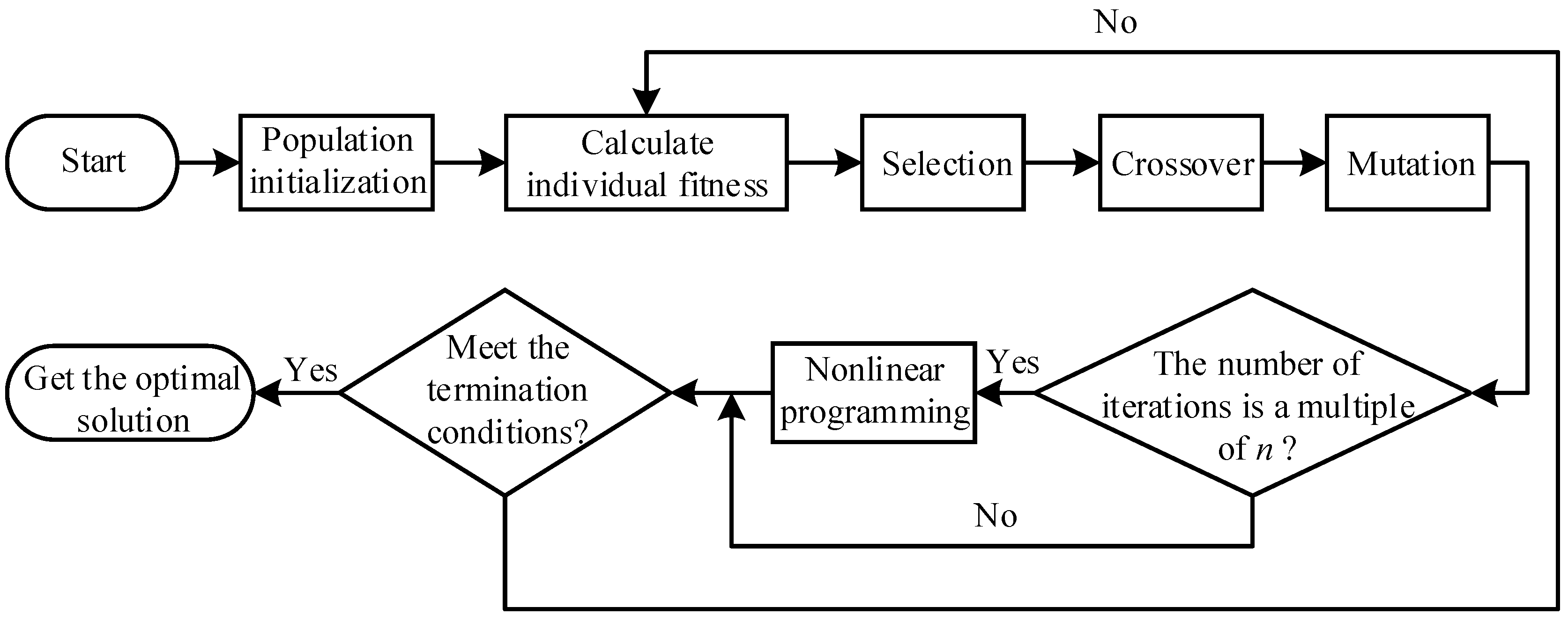
Genetic algorithm has defects such as poor local search ability and sometimes it can only get the suboptimal solution of the problem, not the optimal solution. Therefore, on the basis of using genetic algorithm for global solution scheme, the nonlinear programming algorithm is used for local solution scheme to obtain the global optimal solution of the problem. The flowchart of the improved genetic algorithm is shown in Figure 10.
The steps of the improved genetic algorithm are described in detail as follows:
(1) Population initialization.
The paper adopts the real number coding method, and each chromosome is a real number vector.
(2) Individual fitness.
The fitness function is the standard to evaluate the quality of individuals in a population. It is generally obtained by transforming the objective function. In the paper, the objective function of the optimization model is taken as the fitness function.
(3) Selection.
Selection is based on the sorting results of individuals according to fitness values to eliminate poor individuals, and retain excellent individuals to pass on to the next generation. The paper uses the roulette wheel selection, the probability of individual selection pi is as follow:
p i = f i j = 1 N f j
fi is the individual fitness value; N is the total number of individuals in the population.
(4) Crossover.
Crossover is to simulate the sexual reproduction process of natural organisms. It exchange some genes between two jointed chromosomes according to the crossover probability to form two new individuals. Since individuals are encoded by real numbers, the real number crossover method is used in the paper to simulate the uniform crossover of binary representation. The crossover operation method of the kth chromosome ak and the lth chromosome al at position j is as follow:
{ a k j = a k j ( 1 b ) + a l j b a l j = a l j ( 1 b ) + a k j b
b is a random number in the interval [0,1].
(5) Mutation.
Mutation refers to the replacement of certain gene values in the individual code string with other gene values according to the mutation probability to form a new individual. The paper uses Gaussian mutation operator, which means to replacing the original gene value with a random number conforming to the normal distribution of mean μ and variance σ2 during mutation operation. Assuming that there are 12 random numbers r i ( i = 1 , 2 , , 12 ) uniformly distributed in the range of [0,1], a random number conforming to the normal distribution N ( μ , σ 2 ) can be obtained by the following equation:
Q = μ + σ ( i = 1 12 r i 6 )
When Gaussian mutation operation is performed from X = x 1 x 2 x k x l to X = x 1 x 2 x k ' x l , the value range of gene value at mutation point x k ' is [ U min k , U max k ] , and assume as follow:
{ μ = U max k + U min k 2 σ = U max k + U min k 6
The new gene value x k ' can be determined by the following equation:
x k ' = U max k + U min k 2 + U m ax k + U min k 6 ( i = 1 12 r i 6 )
(6) Nonlinear programming.
Matlab optimization toolbox contains the fmincon function that can be directly called to solve nonlinear programming problems. The function starts from an estimated value to search the minimum value of the nonlinear multivariate function under the constraint condition.

6. Calculation Example of the Paper Folding Metamorphic Mechanism

6.1. Type Synthesis of the Paper Folding Mechanism

The folding process of a cardboard are shown in Figure 11. There are two steps: the first step, from Fig. (a) to Fig. (b), cardboard 1 and cardboard 2 keep relatively static and they are folded into 90° along the crease between 2 and 3. In the second step, from Fig. (b) to Fig. (c), cardboard 2 and cardboard 3 keep relatively static and they are folded into 90° along the crease between 1 and 2.
To the first step of folding paper in the horizontal direction , it could be completed by using a crank-slider mechanism. To the second step in the vertical direction, it could be completed by using a crank-rocker mechanism. Based on the structural design of the metamorphic revolute joint in Section 3.2, the kinematic diagram of a 2-DOF constrained metamorphic mechanism with two working configurations which could perform the whole folding process is shown in Figure 12. The constrained metamorphic mechanism is divided into three parts: the driving link, RRR Assur group and RRRP augmented Assur group. The RRRP group could switch between the crank-slider mechanism and the crank-rocker mechanism. The ahead RRR group reduces the maximum compression of the spring in the metamorphic revolute joint E. The other spring connected to the slider makes the speed and acceleration change relatively stable during the movement of the slider, and weakens the shock and vibration [45].
The structural parameters and tolerances produced in manufacturing process of the paper folding mechanism are shown in Table 1, and the variation ranges of some kinematic parameters are shown in Table 2. In the table, k1, k2, a, b are the stiffness and original length of spring 1 and spring 2, d1 and d2 are the distances between the installation positions of spring 1 on link EF and link CE and the point E as shown in Figure 5,. Moreover, α is the geometric constraint angle of the metamorphic revolute joint E (the maximum angle of ∠CEF), and Δθ1 is the input angle error of the driving link. Finally, It is assumed that all the parameters in Table 1 follow with normal distribution, and the value of mean μi and standard deviation σi of each parameter follow the “3σ” principle.

6.2. Reliability Calculation of the Configuration Transformation Ability of the Paper Folding Mechanism

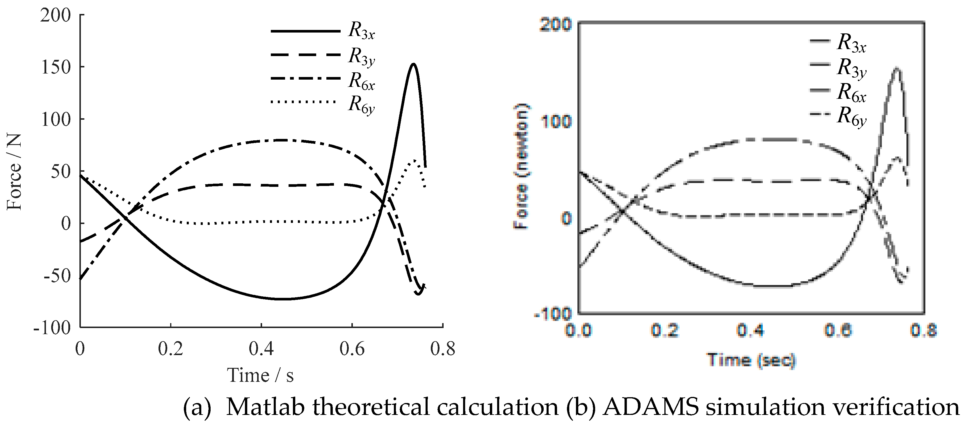
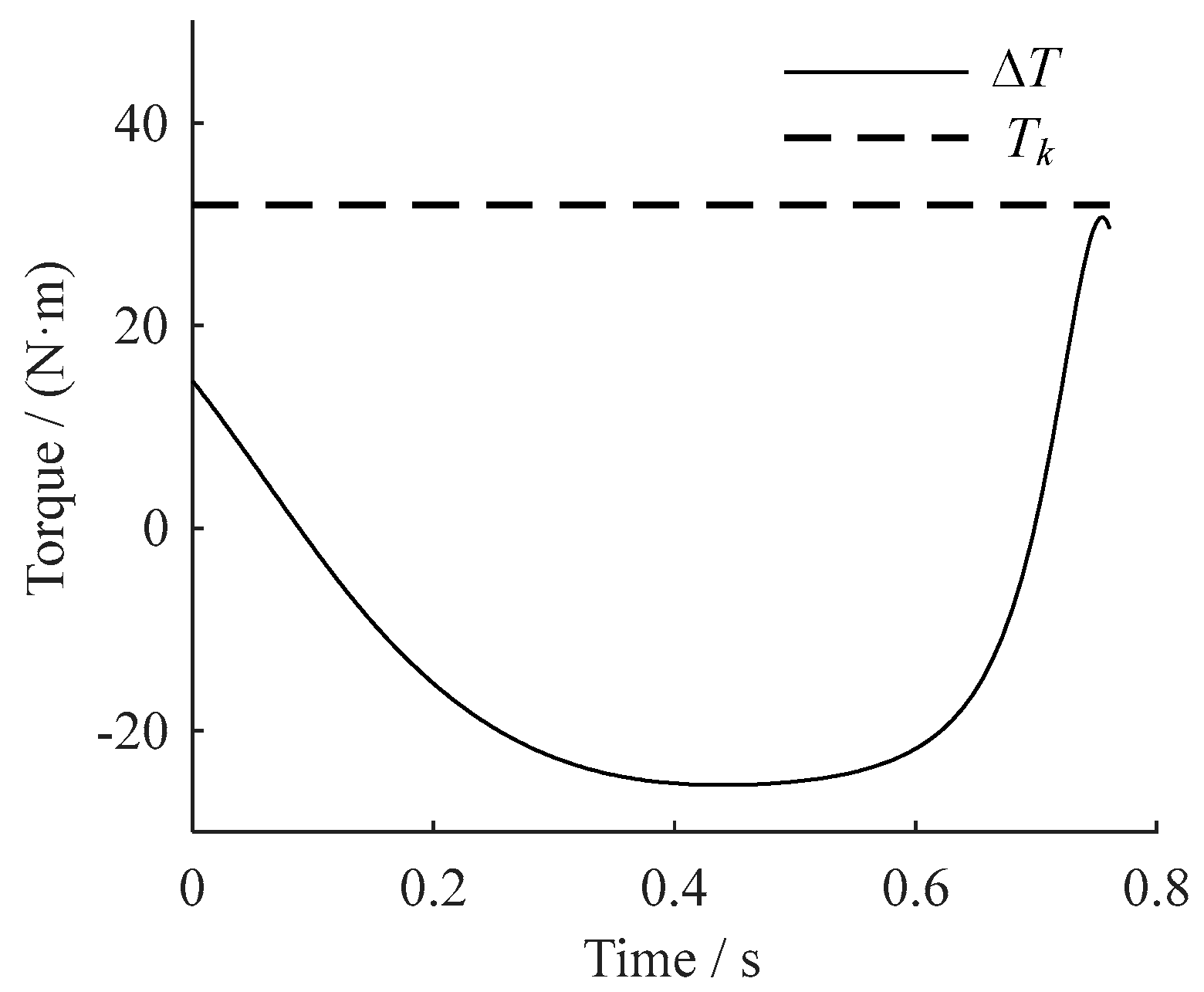
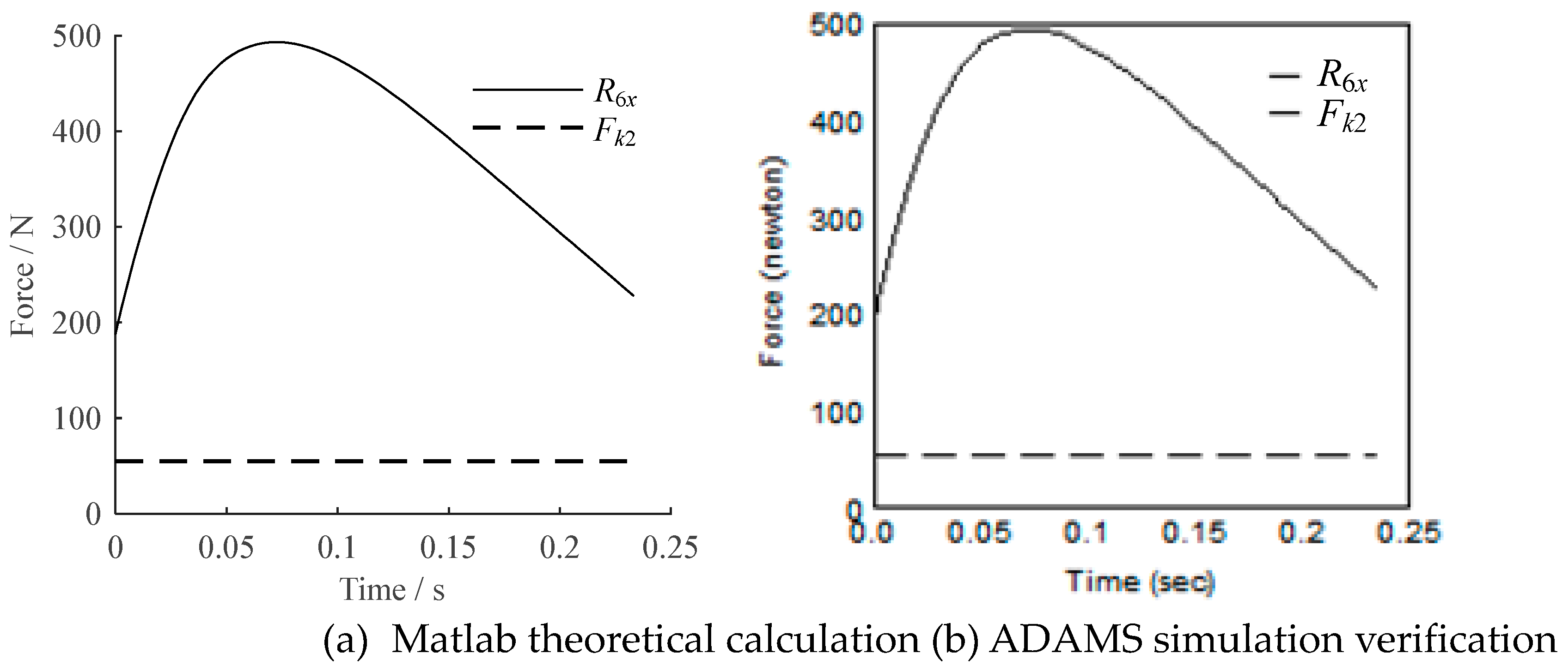
Based on the theoretical calculation model, the kinematic and force analysis of the paper folding mechanism are calculated by MATLAB, and some results are verified by a simulation software package (ADAMS). The comparisons between the results of two calculation methods are shown in Figure 13, Figure 14 and Figure 15. It can be seen from Figure 13 that the Matlab calculation of some key mechanical performance parameters in the working configuration I is the same as the ADAMS simulation results, which verifies the correctness of the mathematical model of the kinematic and force analysis of the paper folding mechanism. As can be seen from Figure 14, in the whole working configuration I, the driving torque of the metamorphic joint E is less than the constrained torque provided by the spring. Therefore, the metamorphic joint E is always in a constrained state, and the components CE and EF always remain relatively static. From Figure 15, the calculation results of some key mechanical performance parameters in the working configuration II are the same by the two methods. In addition, in the whole working configuration II, due to the reaction force on the slider along the horizontal direction is always to the right and greater than the spring force in the left direction, the driving force on the slider, the reaction force along the horizontal component and the spring force is always to the right. The slider is always constrained due to geometric constraint.
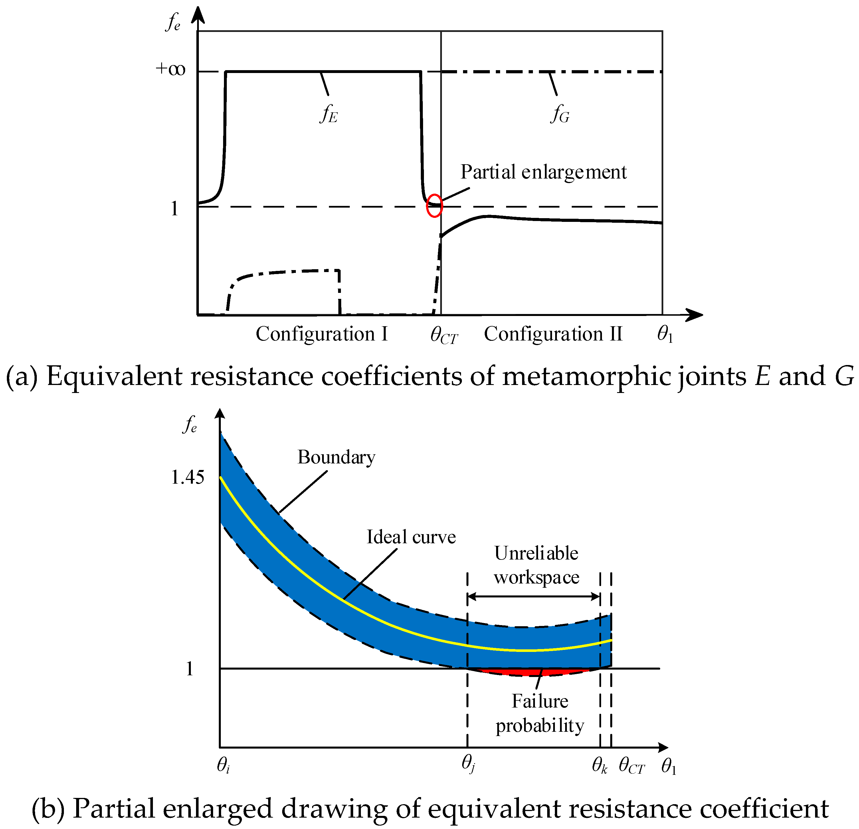
The equivalent resistance coefficients fE and fG of metamorphic joints E and G are shown in Figure 16(a), and a partial enlarged drawing of fE near the configuration transforming moment in the working configuration I is shown in Figure 16(b). Because of the uncertainty of each parameter in Table 1, the kinematic status transformation of metamorphic revolute joint RE is likely to be advanced or delayed, which can lead to undesired working sequence. During the working configuration II, the equivalent resistance coefficient fG of joint PG is positive infinity. However, the reaction force to the right and the spring force to the left are almost similar to each other at the adjacent moment of the configuration transforming according to the force analysis. Therefore, due to the fluctuation of each parameter in Table 1 at these moments which may make the slider have a tendency to move to the left and lead to unexpected working sequence of the mechanism, it is necessary to verify their values again.
Based on the probabilistic evaluation model of configuration transforming ability described in Section 4.3, the reliabilities at the moment of configuration transforming and the adjacent moments in the working configuration I and II are respectively calculated. Then, the interval reliability of the configuration transforming ability is obtained by multiplying them. When calculating the reliability of the adjacent moment, the reliability is calculated by taking an adjacent moment every 1° from the adjacent moment to the moment far away from the configuration transformation until the value of the reliability is 1. The results of reliability theory calculation and Monte Carlo simulation (MCS) are shown in Table 3 during the working configuration I, the moment of the configuration transforming, and the working configuration II.
According to Eq. (38), the interval reliability of configuration transforming ability of the paper folding mechanism is as follow:
R g = R 11 R 12 R 16 R c R 21 = 0.9804

6.3. The Optimization Design of Reliability for Configuration Transformation of the Paper Folding Mechanism

The sensitivity calculation model includes the position angle parameter of the driving link. According to the reliability calculation result of the paper folding mechanism, the reliability is the lowest when the position angle of the driving link is -18°. The moment is taken as an example to calculate the variance sensitivity coefficient of each structural parameter. The parameters of the paper folding mechanism are taken into Eqs. (40)-(42), and the calculation results are shown in Table 4.
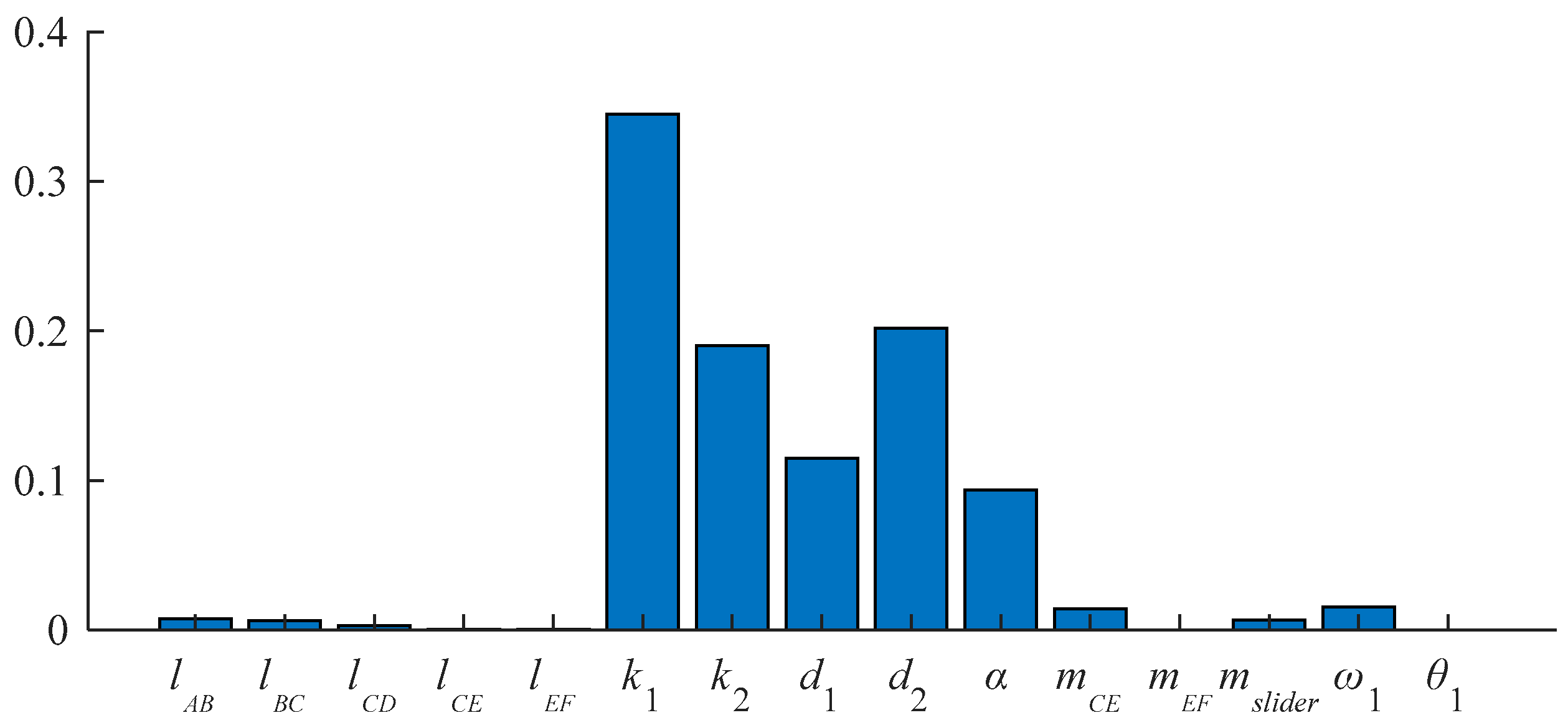
In order to more intuitively reflect the size relationship of variance sensitivity coefficient of each parameter, the histogram of variance sensitivity coefficient is drawn, as shown in Figure 17.
As can be seen from Figure 17, the variances of the five parameters k1, k2, d1, d2, and α have a greater impact on the reliability, and the variance of other parameters has a negligible impact on the reliability. In the reliability optimization design, the tolerances of these 5 parameters are taken as design variables, and the tolerances of other parameters are taken as given values, so that the paper folding mechanism can meet the reliability requirements under the condition of considering economy.
The optimization model of the paper folding mechanism is as follow:
{ cos t ( x ) = i = 1 5 k i ( c i ) 0.7 s . t . R n 0.9995 0.005 c 1 0.01 0.01 c 2 0.02 0.003 c 3 0.007 0.003 c 4 0.006 0.007 c 5 0.014
ki and ci are the cost weight coefficient and variation coefficient of optimization design variables respectively. Since the processing cost increases exponentially with the increase of the reliability requirement of the configuration transformation, the reliability requirement is given as 0.9995, so that the processing cost is controlled as much as possible on the premise of ensuring that the paper folding mechanism has high reliability of repeated operations.
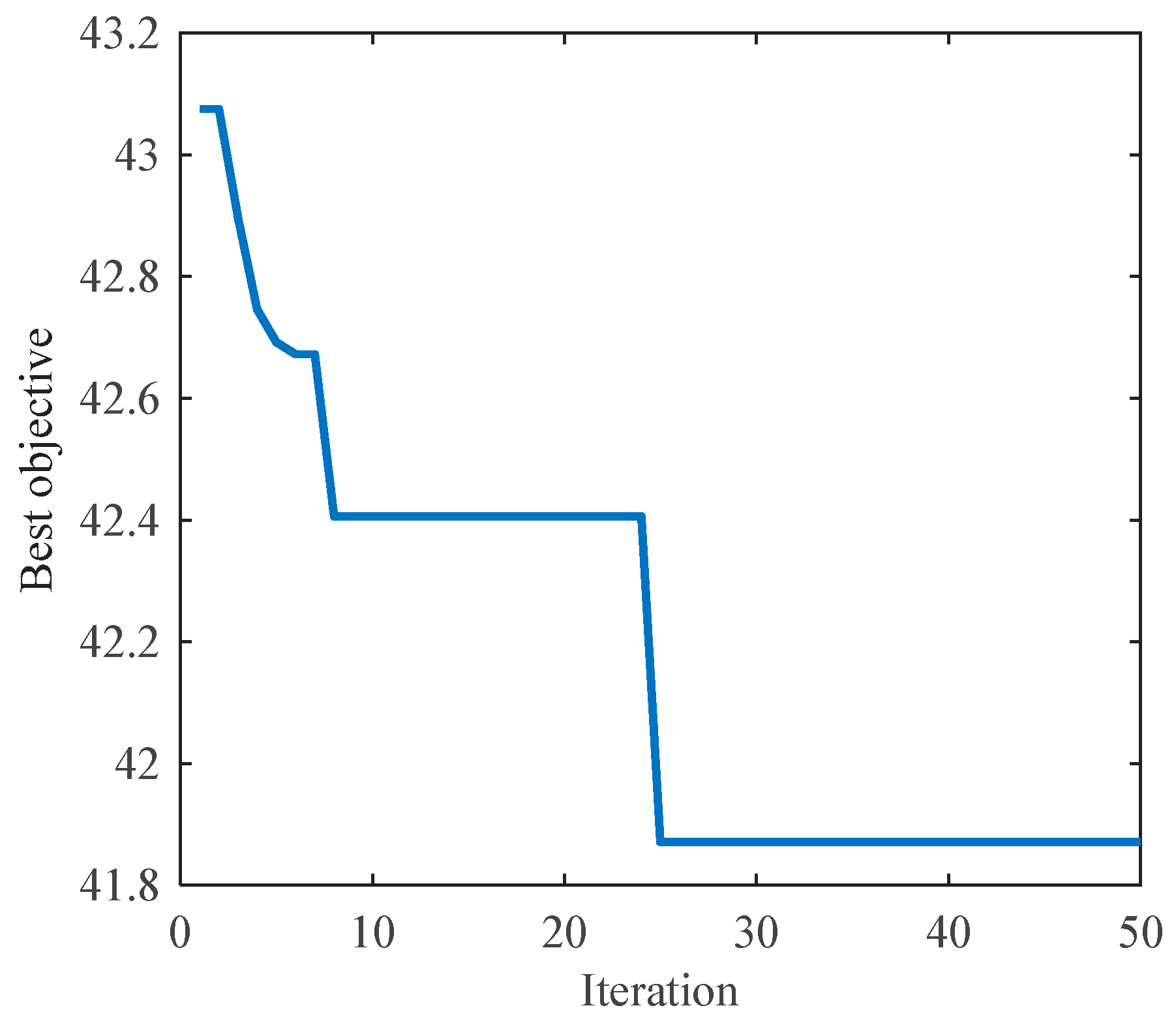
In the improved genetic algorithm, the population size is 100, the number of chromosomes is 5, and the number of iterations is 50. The program is programmed with MATLAB to find the optimal solution of tolerance distribution of each parameter of the paper folding mechanism by using the optimization model. The convergence of the best objective during the optimization process is shown in Figure 18, and the partial enlarged drawing of the optimized equivalent resistance gradient curve of the paper folding mechanism at the adjacent moments of the configuration transforming in the working configuration I is shown in Figure 19.
The optimization results show that when the iteration reaches 25 times, the optimal fitness value which is the relative cost value obtained by the weight is 41.8704. The tolerances of the 5 parameters after optimization are as follow: T k 1 = 0.348 N / m , T k 2 = 0.0303 N / m , T d 1 = 2.58 mm , T d 2 = 2.736 mm and T α = 1.01 . From the comparison of the partial enlarged drawing of the equivalent resistance coefficient before and after the optimization of the paper folding mechanism (Figure 16(b) and Figure 19), it can be seen that after optimization, the fluctuation range of the equivalent resistance coefficient at any time is reduced, the unreliable workspace is reduced, and the failure probability of mechanism configuration transformation is reduced (the area of the shaded part in Figure 19 is smaller than that in Figure 16(b)). As shown in Table 5, three discrete points with low reliability at configuration transforming moment are selected to compare the changes of equivalent resistance coefficient before and after optimization. Meanwhile, the optimization effect can also be seen in Table 5. The tolerance values of the optimization parameters are taken into the reliability calculation formula of the configuration transformation of the metamorphic mechanism, and the reliability of the configuration transformation ability of the paper folding mechanism is increased from 0.9804 to 0.9995. Therefore, through the reliability optimization design of the paper folding mechanism, the optimal allocation scheme of each parameter tolerance that meets the given reliability and economic requirements is obtained.

7. Conclusions

After reviewing structure composition principle of the constrained metamorphic mechanism based on the augmented Assur group, the modularized force analysis methods are proposed by taking the driving link, the Assur group and the augmented Assur group containing metamorphic joints as basic units. Based on the definition of the equivalent resistance coefficients of metamorphic joints, the evaluation model of the configuration transforming ability under deterministic conditions is established. Considering the randomness of input errors in the deterministic model, a generalized probabilistic evaluation model for describing the configuration transforming ability of the constrained metamorphic mechanism is established by using the theory of reliability.
Based on the reliability calculation model of the configuration transformation of the constrained metamorphic mechanism, the reliability sensitivity of internal and external parameters of the system is analyzed, the structural parameter tolerances with high sensitivity are selected as the design variable. Moreover, a reliability optimization model is established with the tolerance cost model as the objective function and the given reliability of the configuration transformation of the metamorphic mechanism and the tolerance range of each structural parameter as the constraints, so that the optimization scheme satisfies the requirements of reliability and economy at the same time.
(3) Taking the paper folding metamorphic mechanism as an example, the feasibility and effectiveness of the reliability optimization design method are verified. Then, the reliability calculation and reliability optimization design of configuration transformation ability of the paper folding mechanism are completed. The reliability calculation results show that the reliability at the configuration transforming moment is R=1, and the interval reliability of configuration transforming is R=0.9804. The optimization results show that after redistributing the tolerances of key parameters, the fluctuation range of the equivalent resistance coefficient of the paper folding mechanism is reduced, and the interval reliability of the configuration transformation is increased from R=0.9804 to R=0.9995. The optimization results satisfies the given reliability requirements and reduces the cost.

Acknowledgments

The work is financially supported by the National Natural Science Foundation of China (Grant No. 51575091), Open Project of Key Laboratory of Lifting Equipment’s Safety Technology for State Market Regulation (Grant No. 2023KF002) and the Fundamental Research Funds for the Central Universities (Grant No. N2203010).

References

  1. Dai, J. S., and Jones, J. R., 1999, “Mobility in Metamorphic Mechanisms of Foldable/Erectable Kinds,” Journal of Mechanical Design, 121(3), 375-382. [CrossRef]
  2. Jin, G. G., Zhang, Q. X., Dai, J. S., and Li, D.L., 2003 “Dynamic modeling of metamorphic mechanism,” Chinese Journal of Mechanical Engineering, 16(1), 94-99.
  3. Dai, J. S., Ding, X. L., and Zou, H. J., 2005, “Fundamentals and categorization of metamorphic mechanism,” Chinese Journal of Mechanical Engineering, (06), 7-12.
  4. Guo, Z. H., Ma, L. Z., and Yang, Q. Z., 2005, “Topological type analysis of the variable freedom mechanism based on the metamorphic principle,” China Mechanical Engineering, 016(001), 3-5+9.
  5. Lan, Z. H., and Du, R., 2008, “Representation of Topological Changes in Metamorphic Mechanisms With Matrices of the Same Dimension,” Journal of Mechanical Design, 130(7), 074501-1-4. [CrossRef]
  6. Li, S. J., and Dai, J. S., 2012, “Structure synthesis of single—driven metamorphic mechanisms based on the augmented Assur groups,” Journal of Mechanisms and Robotics, 4(3), 031004-1-8. [CrossRef]
  7. Li, S. J., and Dai, J. S., 2012, “Advances in reconfigurable mechanisms and robotics Ⅰ,” Tianjin, Springer Press, 53-62.
  8. Kanner, O., and Dollar, A., 2013, “Kinematic Design of an Underactuated Robot Leg for Passive Terrain Adaptability and Stability,” Journal of Mechanisms and Robotics, 5(3), 031006-1-9. [CrossRef]
  9. Coppola, G., Zhang, D., Liu, K. F., and Gao, Z., 2013, “Design of Parallel Mechanisms for Flexible Manufacturing With Reconfigurable Dynamics,” Journal of mechanical design, 135(7), 071011-1-10. [CrossRef]
  10. Wang, R. G., Chen, H. Q., Li, Y. X., Zou, Q. M., and Zheng, A. P., 2014, “Nonlinear dynamic model and simulation of a novel controllable metamorphic palletizing robot mechanism,” Proc. 2014 IFToMM Asian Conference on Mechanism and Machine Science, DYMl-4.
  11. Yang, Q., Wang, H. G., Li, S. J., and Dai, J. S., 2014, “Type synthesis of constrained metamorphic mechanisms with structural forms of the metamorphic joints,” Journal of Mechanical Engineering, 50(013), 1-8.
  12. Li, S. J., Wang, H. G., and Yang, Q., 2015, “Constraint Force Analysis of Metamorphic Joints Based on the Augmented Assur Groups,” Chinese Journal of Mechanical Engineering, 28(04), 747-755. [CrossRef]
  13. Wang, Q. C., Quan, Q. Q., Deng, Z. Q., and Hou, H. Y., 2016, “An Underactuated Robotic Arm Based on Differential Gears for Capturing Moving Targets: Analysis and Design,” Journal of Mechanisms and Robotics, 8(4), 041012-1-13. [CrossRef]
  14. Aimedee, F., Gogu, G., Dai, J. S., Bouzgarrou, C., and Bouton, N., “Systematization of morphing in reconfigurable mechanisms,” Mechanism and machine theory, 96, 215-224. [CrossRef]
  15. Yan, H. S., and Kuo, C. H., 2006, ‘Topological Representations and Characteristics of Variable Kinematic Joints,” Journal of Mechanical Design, 128(2), 384-391. [CrossRef]
  16. Yan, H. S., and Kang C. H., 2009, “Configuration synthesis of mechanisms with variable topologies,” Mechanism and Machine Theory, 44(5), 896-911.
  17. Gan, D. M., and Dai J. S., 2013, “Geometry constraint and branch motion evolution of 3-PUP parallel mechanisms with bifurcated motion,” Mechanism and Machine Theory, 61, 168-183.
  18. Zhang, K. T., Dai, J. S., and Fang, Y. F., 2013, “Geometric constraint and mobility variation of two 3SvPSv metamorphic parallel mechanisms,” Journal of Mechanical Design, 135(1), 011001-1-8. [CrossRef]
  19. Zlatanov, D. S., Bonev, I., and Gosselin, C., 2002, “Constraint singularities as configuration space singularities,” Advances in Robot Kinematics: Theory and Applications, 183-192.
  20. Gan, D. M., Dai, J. S., Dias, J., and Seneviratne, L., 2013, “Unified kinematics and singularity analysis of a metamorphic parallel mechanism with bifurcated motion,” Journal of Mechanisms and Robotics, 5(3), 031004-1-11. [CrossRef]
  21. Tian, H. B., Ma, H. W., and Ma, K., 2018, “Method for configuration synthesis of metamorphic mechanisms based on functional analyses,” Mechanism and Machine Theory, 123 (6), 27–39. [CrossRef]
  22. Qiao, S. L., Guo, H. W, Liu, R. Q., and Deng, Z. Q., 2019, “Self-adaptive grasp process and equilibrium configuration analysis of a 3-DOF UACT robotic finger,” Mechanism and Machine Theory, 133, 250-266. [CrossRef]
  23. Song, Y. Y., Chang, B. Y., Jin, G. G., Wei, Z., Li, B., and Zhu, Y. J., “Research on Dynamics Modeling and Simulation of Constrained Metamorphic Mechanisms,” Iranian Journal of Science and Technology, Transactions of Mechanical Engineering, 45(2), 321-336. [CrossRef]
  24. Yang, Q., Hao, G. B., Li, S. J., Wang, H. G., and Li, H. Y., 2020, “Practical Structural Design Approach of Multicon guration Planar Single-Loop Metamorphic Mechanism with a Single Actuator,” Chinese Journal of Mechanical Engineering, 33(05), 29-43.
  25. Liu, S. L., Wang, X. D., Kong, J. Y., Zeng, T., and Tang, W., 2021, “Kinematic Reliability Analysis of Planar Metamorphic Mechanism with Multi-source Uncertainties,” Journal of Mechanical Engineering, 57(17), 64-75.
  26. Liao, P., and Lu, J. S., 1999, “A Calculating Metod of Circle Error Using Genetic Algorithms,” Journal of Nanjing University of Aeronautics & Astronautics, 31(4), 393-397.
  27. Pan, F. W., 2006, “Accuracy synthesis of new typed 6 DOF parallel robot based on self-adaptive genetic algorithm,” Journal of Machine Design, 26(8), 28-31.
  28. Pan, F. W., Lu, J. H., and He L. L., 2009, “Analysis of Kinematics of a Novel 6-DOF Parallel Platform Based on Genetic Algorithm,” Machine Tool & Hydraulics, 37(1), 37-40.
  29. Chen, X. L., and Sun, X. Y., 2012, “Dexterity analysis of a 4-ups-rps parallel mechanism,” International Journal of Advanced Robotic Systems, 144(9), 1-8. [CrossRef]
  30. Chen X. L., Jiang, D. Y., Chen, L. L, and Wang, Q., 2016, “Kinematics Performance Analysis and Optimal Design of Redundant Actuation Parallel Mechanism,” Transactions of the Chinese Society for Agricultural Machinery, 47(6), 340-347.
  31. Ni, Y. B., Shao, C. Y., Zhang, B., and Guo, W., X., 2016, “Error modeling and tolerance design of a parallel manipulator with full-circle rotation,” Advances in Mechanical Engineering, 8(5), 1687814016649300. [CrossRef]
  32. Xiong, Y., 2017, “Optimal Design of Double-stage Wheel Hub Reducer System based on Fuzzy Theory,” Journal of Mechanical Transmission, 41(07), 180-187.
  33. Kang, X., and Dai, J. S., 2020, “Theoretical Difficulties and Research Progresses of Mechanism Reconfiguration in Mechanisms——Evolution Connotation, Furcation Principle, Design Synthesis and Application of Metamorphic Mechanisms,” China Mechanical Engineering, 31 (01), 57-71.
  34. Yu, J. J., Liu, K., and Kong X. W., 2020, “State of the Art of Multi-mode Mechanisms,” Journal of Mechanical Engineering, 56(19), 14-27.
  35. Wang, R. G., Chen, and H. Q., 2021, “Analysis and Optimization on Kinematic Reliability of Metamorphic Mechanisms with Multiple Failure Modes,” Journal of Mechanical Engineering, 57(11), 184-194.
  36. Li, S. J., 1995, “A Method of Disassembling Assur-Groups for IDENTIFYING and Modelling by Computer,” Journal of Northeastern University, (2): 198-201.
  37. Huang, P., and Ding H. F., 2019, “Structural synthesis of Assur groups with up to 12 links and creation of their classified databases,” Mechanism and Machine Theory, 145(C): 103668.
  38. Simionescu, P. A., 2019, “Kinematics of the RRR, RRT (Passive) and RRRR, RRRT (Active) Linkage-Mechanism Building Blocks with Applications and Reporting of New Findings,” Journal of Mechanisms and Robotics, 11(6), 1-24. [CrossRef]
  39. Xie, L. Y., 2014, “Issues and Commentary on Mechanical Reliability Theories, Methods and Models,” Journal of Mechanical Engineering, 50(14), 27-35.
  40. Shan, S., and Wang, G. G., 2008, “Reliable design space and complete single-loop reliability-based design optimization,” Reliability Engineering & System Safety, 93(8), 1218-1230. [CrossRef]
  41. Zhang, Y. M., Huang, X. Z., He X. D., and Song X. Q., 2008, “Reliable sensitivity design for kinematics accuracy of planar linkage mechanism,” Journal of Engineering Design, 2008(01), 25-28.
  42. Zhang, Y. M., Zhu, L. S., Tang, L., and Lu, H., 2011, “Dynamical Stress Reliability and Sensitivity Analysis of Nonlinear Rotor System with Rigid-flexible Structure,” Journal of Mechanical Engineering, 047(002), 159-165.
  43. Yan, Z., and Guo R. L., 2013, “Precision optimization design of plane mechanism with gap,” Machinery, 51(10), 42-44.
  44. Li, X. P., Mao X., Gao J. Z., and Wang B. B., 2017, “Impact Analysis of the Parameters Variation on the Dynamic Performance of the Constraints Metamorphic Mechanism,” Mechanical design & manufacturing, 2017(12), 90-93.
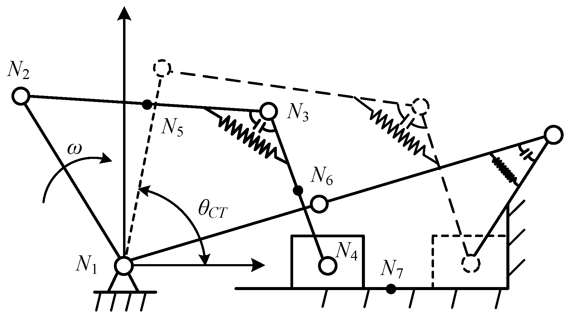
Figure 1. 2-DOF constrained metamorphic mechanism.
Preprints 110076 g001
Figure 2. Metamorphic cyclogram of the 2-DOF constrained metamorphic mechanism.
Preprints 110076 g002
Figure 3. Nine structural forms of class II augmented Assur group.
Preprints 110076 g003aPreprints 110076 g003b
Figure 4. Metamorphic process of RRRP group.
Preprints 110076 g004
Figure 5. Force diagram of RRP group degraded by RRRP group.
Preprints 110076 g005
Figure 6. Force diagram of RRR group degraded by RRRP group.
Preprints 110076 g006
Figure 7. Structure of metamorphic revolute joint.
Preprints 110076 g007
Figure 8. Actual equivalent resistance coefficients of working configuration II .
Preprints 110076 g008
Figure 9. Actual equivalent resistance coefficients of working configuration I and II.
Preprints 110076 g009
Figure 10. Improved genetic algorithm flowchart.
Preprints 110076 g010
Figure 11. The folding process of a cardboard.
Preprints 110076 g011
Figure 12. Working-stage of the paper folding metamorphic mechanism.
Preprints 110076 g012aPreprints 110076 g012b
Figure 13. The reaction force of the revolute joint C and the revolute joint F in the working configuration I.
Preprints 110076 g013
Figure 14. The driving torque ΔT and constrained torque Tk of the metamorphic revolute joint E in the working configuration I.
Preprints 110076 g014
Figure 15. The reaction force R6x and spring force Fk2 of the slider in the working configuration II.
Preprints 110076 g015
Figure 16. Equivalent resistance coefficients of the paper folding mechanism.
Preprints 110076 g016
Figure 17. Variance sensitivity coefficient of each parameter of paper folding mechanism.
Preprints 110076 g017
Figure 18. Convergence of the best objective.
Preprints 110076 g018
Figure 19. Partial enlarged drawing of equivalent resistance gradient curve after optimization.
Preprints 110076 g019
Table 1. Structural parameters and tolerances of the paper folding mechanism.
Parameter Value Parameter Value Parameter Value
lAB/mm 180±0.125 lBC/mm 360±0.18 lCD/mm 240±0.145
lCE/mm 360±0.18 lEF/mm 210±0.145 lAD/mm 315
maxlAF/mm 870 mAB/kg N~(1,0.007) mBC/kg N~(1.5,0.01)
mCD/kg N~(1,0.007) mCE/kg N~(1.5,0.01) mEF/kg N~(2,0.013)
mslider/kg N~(1,0.007) JAB/(kg·m2) 0.0027 JBC/(kg·m2) 0.0162
JCD/(kg·m2) 0.0048 JCE/(kg·m2) 0.0162 JEF/(kg·m2) 0.00735
a/mm 250 k1/(N/mm) N~(10,0.1) d1/mm N~(100,0.667)
d2/mm N~(120,0.667) b/mm 76 k2/(N/mm) N~(0.5,0.01)
ω1/(rad/s) N~(2π,0.01) α N~(120.3,0.167) Δθ1 N~(0,0.067)
Table 2. The variation ranges of some kinematic parameters of the paper folding mechanism.
Configuration I Configuration II
Type of mechanism Crank slider Crank rocker
Driving link angle -290.2°~-15.2° -15.2°~69.8°
Angle of joint E Static(120.3°) 120.3°~72.5°
Position of slider 598.5mm~870mm Static(870mm)
Angle of rocker Static(115.9°) 115.9°~88.8°
Table 3. The results of reliability theory calculation and Monte Carlo simulation.
Configuration Angle μZ σZ β Reliability MCS
Conf. I -21° 2.5817 0.5194 4.9705 1 1
Conf. I -20° 1.7918 0.5256 3.4088 0.9997 0.9996
Conf. I -19° 1.3314 0.5337 2.4947 0.9937 0.9633
Conf. I -18° 1.2474 0.5440 2.2930 0.9891 0.9886
Conf. I -17° 1.5846 0.5570 2.8449 0.9978 0.9981
Conf. I -16° 2.3832 0.5729 4.1599 1 1
Transformation moment -15.2° 42.1336 1.0606 39.7262 1 1
Conf. II -15° 132.4779 3.8848 34.1016 1 1
Table 4. Variance sensitivity coefficient of each structural parameter of paper folding mechanism.
Parameter Sensitivity coefficient Parameter Sensitivity coefficient Parameter Sensitivity coefficient
lAB 0.0075 lBC 0.0065 lCD 0.0030
lCE 0.0003 lEF 0.0003 k1 0.3449
k2 0.1904 d1 0.1149 d2 0.2019
α 0.0937 mCE 0.0142 mEF 0.0001
mslider 0.0067 ω1 0.0155 θ1 0.0002
Table 5. Comparison of equivalent resistance coefficient before and after optimization.
Moment Equivalent resistance coefficient fe Before optimization After optimization
-17° Mean value 1.0522 1.0522
Fluctuation range 14.27% 9.64%
Failure probability 0.21% 0
-18° Mean value 1.0406 1.0406
Fluctuation range 13.84% 9.41%
Failure probability 1.09% 0.03%
-19° Mean value 1.0435 1.0435
Fluctuation range 13.53% 9.30%
Failure probability 0.63% 0.01%
Disclaimer/Publisher’s Note: The statements, opinions and data contained in all publications are solely those of the individual author(s) and contributor(s) and not of MDPI and/or the editor(s). MDPI and/or the editor(s) disclaim responsibility for any injury to people or property resulting from any ideas, methods, instructions or products referred to in the content.
Copyright: This open access article is published under a Creative Commons CC BY 4.0 license, which permit the free download, distribution, and reuse, provided that the author and preprint are cited in any reuse.
Prerpints.org logo

Preprints.org is a free preprint server supported by MDPI in Basel, Switzerland.

Subscribe

© 2024 MDPI (Basel, Switzerland) unless otherwise stated