Preprint
Article

Planar Rectangular Microstrip Antenna for Partial Discharge Detection: Experimental Validation on Oil-Filled Transformer Tank

Altmetrics

Downloads

142

Views

65

Comments

0

A peer-reviewed article of this preprint also exists.

Submitted:

25 June 2024

Posted:

26 June 2024

You are already at the latest version

Alerts
Abstract
A Partial discharge (PD) occurrence in high-voltage (HV) and medium-voltage (MV) power assets is a warning sign of insulation system degradation or defective manufacturing/assembly, that may cause catastrophic damage and eventually lead to the breakdown of the power equipment. Ultra-high frequency (UHF) PD measurement technology has extensively been used to monitor the insulation health of the HV or MV equipment due to its high immunity against ambient noise and conducted disturbances. This paper presents experimental validation of a new design of a UHF planar rectangular microstrip antenna that can be used for PD monitoring of HV and/or MV power equipment, such as power transformers. The designed planar rectangular microstrip antenna has a compact size of 80mmx70mmx1.6mm. Laboratory experiments were performed to validate the antenna sensitivity to PD activity caused by insulation defects created inside an oil-filled transformer tank model. PD measurement results confirm that the proposed rectangular microstrip antenna has high sensitivity and high signal-to-noise ratio (SNR), thanks to its capability to suppress external noise disturbances, especially during online PD monitoring. Thus, the proposed UHF antenna seems to be a promising and alternative PD sensor that can be employed in UHF PD monitoring systems of HV or MV power equipment.
Keywords: 
Subject: Engineering  -   Electrical and Electronic Engineering

1. Introduction

High Voltage (HV) and medium voltage (MV) power apparatuses, such as power transformers, play a fundamental role in electrical power system network. During its operation, a power transformer, like any other HV or MV equipment, may experience various stresses such as electrical, mechanical stress, thermal and even environmental stresses, which may result in short or long-term insulation degradation, depending on the extent of stress [1,2]. Quality and conditions of an insulation system, such as oil-paper insulation in power transformers, directly determines power system reliability and availability. Any defect, such as void in solid insulation (paper or pressboard) or gas-filled bubbles in oil, may potentially induce PD activity, which in turn, if not detected at an early stage, may lead to degradation of the entire power transformer insulation system and, eventually, to breakdown (sometimes catastrophic) of a power transformer [3].
PD can be detected using off-line or on-line detection modes. In the literature, on-line PD monitoring has been gaining much attention from many researchers due to the fact that the equipment under test does not need to be switched off when conducting PD measurements, which in turn, would result into power outages for the utility customers, as well as power system disturbances due to subsequent switching on and off operations [4,5]. In addition, on-line PD monitoring is effectively related to transformer real operating conditions, thus being sensitive to temperature, oil flow, mechanical stress.
The conventional PD measurement technique is referred to as electrical method, and described in IEC60270, [6]. The electrical method uses electromagnetic sensors, as capacitors or high-frequency current transformers (HFCT) to capture PD pulses from the object under test. Bandwidth is generally limited to tens of MHz; thus, it is suitable to detect PD that propagated through conductive/inductive paths.
UHF method is, on the contrary, sensitive to irradiated signals, that propagate through dielectric windows present in most electrical and electronic equipment. Ax an example, it has been applied for online/onsite PD monitoring on HV and MV power transformers, switchgears, circuit breakers, rotating machines, taking profit of its strong immunity against ambient noises due to, e.g., electromagnetic interferences from telecommunication and corona discharges [7,8,9]. Therefore, for some applications UHF technology may exhibit high signal-to-noise ratio (SNR) compared to other technologies, such as electrical and acoustic methods. In addition, UHF PD measurements have been exploited for PD source localization, either as a standalone method or combined with acoustic method [10].
UHF sensors (antennas) play a key role in UHF PD detection, being used to capture electromagnetic irradiated waves generated by PD activity. UHF antennas used for PD detection are divided into two categories: internal antennas (built-in antennas) and external antennas [11,12], based on their location on an electrical apparatus. Internal antennas are generally installed via oil-drain valves, while external antennas can be mounted on the transformer tank wall via dielectric windows [13,14]. For the case of gas-insulated switchgears (GIS), the built-in antennas are mounted on the grounded metallic wall of the GIS, while external antennas can be installed across the end-spacer and dielectric windows. For internal use, planar antennas are preferrable compared to monopole antennas, due to smaller dimensions and safety distance (clearance). In addition, planar antennas can be easily mounted on the dielectric windows [7].
Many studies about the design and application of UHF antennas for PD detection on various power system assets have been presented in literature over the past years. For example, A. A. Zahed, et al. designed a fourth order Hilbert fractal antennas that was used to detect PD generated by artificial insulation defect on oil-filled metal tank [15]. In another study conducted by Y. R. Yadam et al., a planar ultra-wideband Archimedean spiral antenna was designed for partial discharge detection, applying a prototype of this antenna to detect PD in air-insulated test cell [16]. Y. Qi et al. proposed an ultra-wideband UHF metal-mountable antenna for partial discharge detection, showing good effectiveness in detecting PD due to surface discharge of contaminated polymeric insulator, [17]. An ultra-wide band circular microstrip antenna was devised for PD monitoring on high voltage air-insulated system (AIS) and oil-insulated system (OIS) [18]. Recently, Azam et al. implemented a planar rectangular microstrip antenna for PD detection in an open substation [19]. A planar elliptical monopole antenna was proposed to detect PD on oil-filled tank in [20]. A bio-inspired printed monopole antenna was applied for PD detection on oil-filled test cell [21]. A UHF microstrip circular antenna was designed for PD detection in power transformers, using a prototype was applied to detect PD on oil-filled test cell [22]. In [23], a bow-tie antenna was successfully implemented as UHF sensor for PD detection in air insulation. Fakhru Rozi, et al. designed various types of loop antennas for PD detection in air-insulated system [24]. Yang et al. developed an UWB printed antenna for UHF PD detection in high voltage switchgears, showing good sensitivity performance when applied both in laboratory and onsite [25].
The research described in this paper focuses on application of a planar rectangular microstrip antenna for PD detection in an oil-filled transformer tank model. This antenna has previously been designed, simulated and optimized, as described in [26]. This antenna has ultra-wide bandwidth of 1.24GHz, in the operating frequency range of 1.37GHz-2.61GHz, below -10dB, VSWR less than 2 and high gain and directivity greater than 2dB within the entire working frequency band. Its fabrication methods, measurements by vector network analyzer, and PD measurement results to validate its performance in detecting PD signals were, however, dealt with in generic applications in [26].
This paper presents antenna characterization and performance focusing on PD monitoring on oil-immersed power transformers. The prototype of this antenna is used to detect UHF PD signals emitted by an artificial PD source active in an oil-filled transformer tank model. Sections II and III deal with design, fabrication, and characterization of the antenna. Section IV presents experimental results of measurements on suitable test objects able to generate corona and surface PD, enclosed in a transformer tank, comparing the sensitivity of the proposed antenna with another type of antenna (loop) and a conventional HFCT sensor connected to transformer ground lead.

2. Design and Fabrication of the Antenna

2.1. Design of Planar Rectangular Microstrip Antenna

The type of UHF sensor used to detect PD activity in oil-filled transformer tank is called planar rectangular microstrip antenna. This antenna consists of a rectangular radiating element (patch) lying on one side of the dielectric substrate and a partial ground plane on the other side of the dielectric substrate, with a compact size of 80mm x 70mm x 1.6mm, see Figure 1. The microstrip feedline, whose impedance is 50Ω, was used to connect the radiating to the ground plane. The radiating patch, feedline and the ground plane are all made of annealed copper, 0.035 mm thick. Antenna was fabricated on printed circuit board (PCB), using FR-4 (epoxy) substrate 12 mm thick, whose relative dielectric constant= 4.4 and dielectric loss (tan δ) = 0.02 [25]. Ansys HFSS 15.0 software was used for design, simulation and optimization of the proposed antenna. To improve ultra-wideband characteristics, dimensions of the U-shaped slot created in the radiating patch were varied (in length and width). In addition, impedance matching was optimized evaluating the effect of the feedline width on the antenna frequency response.
Figure 1 depicts the geometrical view and design parameters for the optimized rectangular microstrip antenna with parameters specification as follows: length of substrate (L) = 80mm, width of substrate (W) =70mm, rectangular patch length (Lp) = 40mm, rectangular patch width (Wp) = 42.5mm, length of the ground plane (Lg) = 22.5mm, width of ground plane (Wg) = 70mm, feedline width (Wf)=4.5mm, slot length (Ls) = 35mm and slot width (Ws) = 22mm. Details on simulation and optimization of this antenna can be found in [25].

2.2. Fabrication of Rectangular Microstrip Antenna

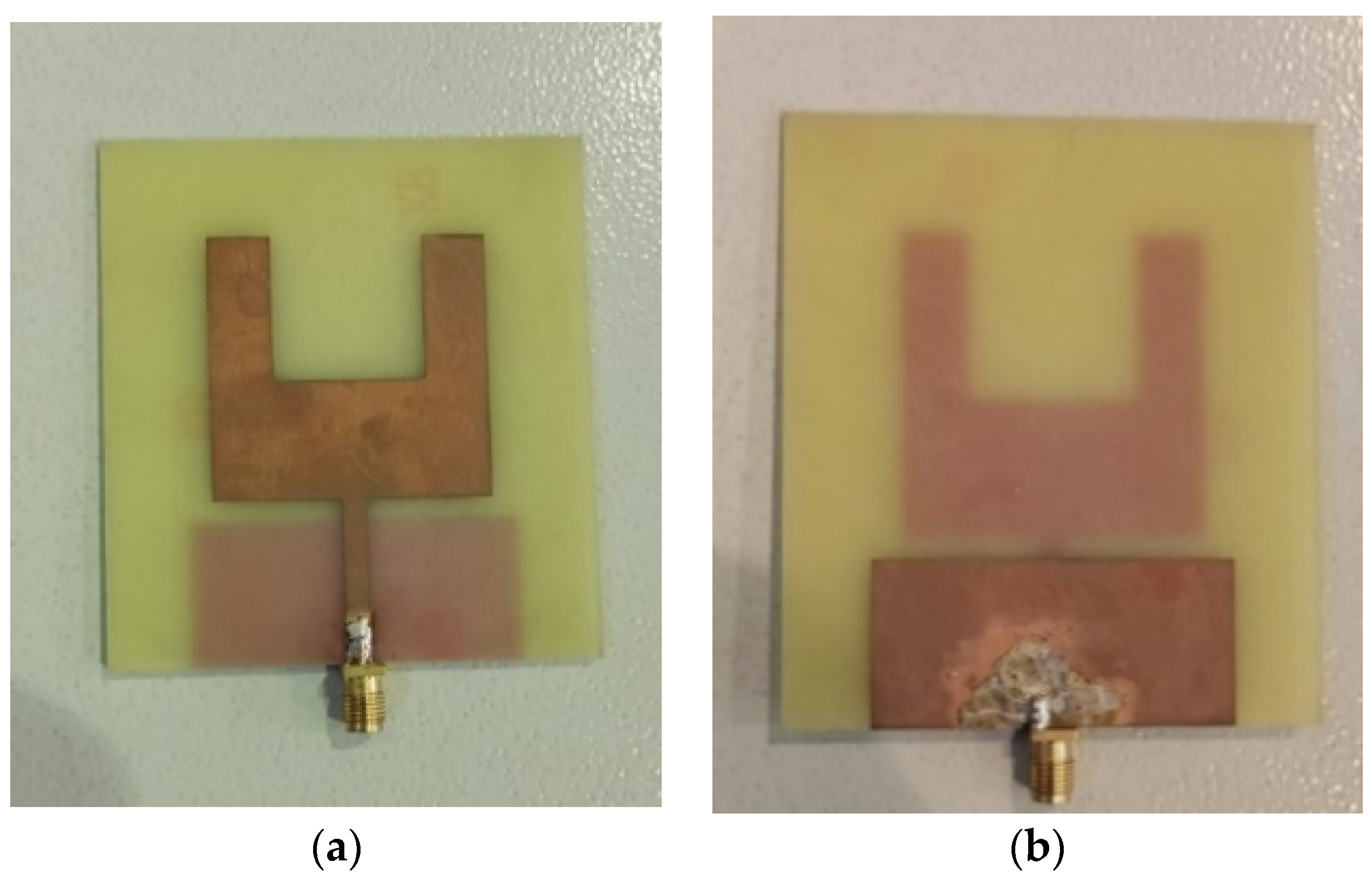
Figure 2 displays the prototype of the proposed rectangular microstrip antenna. For impedance matching purpose, the (SubMiniature version A) SMA connector, whose impedance is 50Ω, was welded on the microstrip feedline as a port that links the antenna to the coaxial cable [19].

2.3. Simulation and Measurement Results

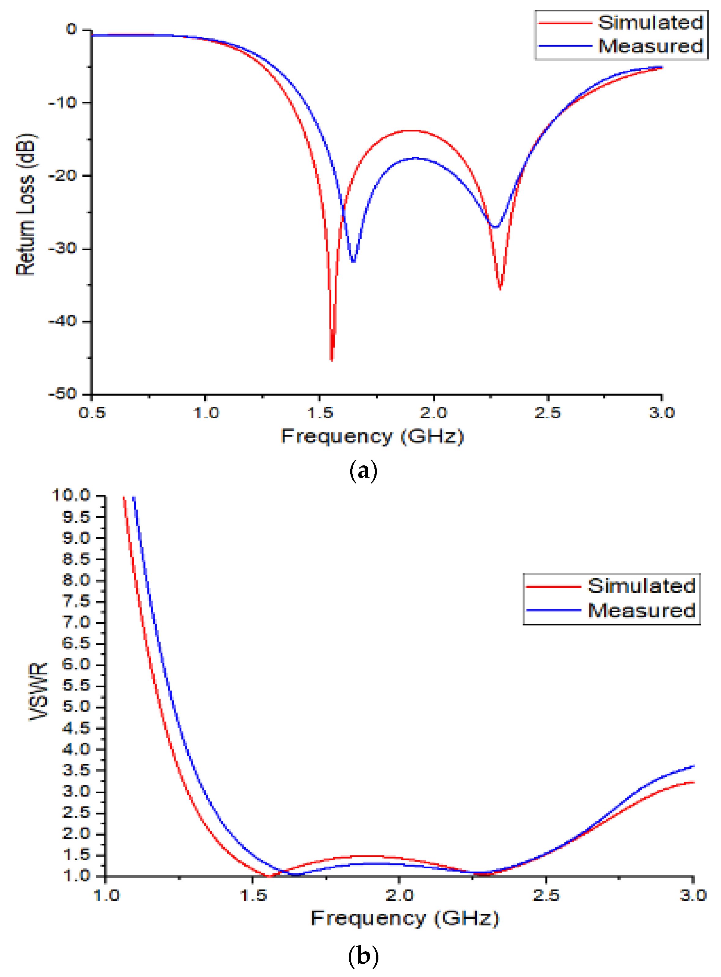
After fabricating the prototype of the proposed rectangular microstrip antenna, the next phase of this research was to measure the antenna basic characteristic parameters, namely return loss (S11), resonant frequency and voltage standing wave ratio (VSWR), as well as its bandwidth. A vector network analyzer (VNA) was used to conduct these measurements. Figure 3a,b illustrate the comparison between simulated and measured return loss and the voltage standing wave ratio, VSWR, of the proposed antenna, respectively. It can be seen that the simulation and measurement results are in a good agreement, except for a slight shift in frequency that could have been caused by fabrication errors or measurement errors. Table 1 summarizes the comparison results between simulation and measurements. Based on simulation results, as depicted in Figure 3a, the designed planar rectangular microstrip antenna has an operating frequency band from 1.37GHz to 2.61GHz, under -10dB, covering an overall impedance bandwidth of 1240MHz.
The simulation results also indicate that the designed rectangular antenna has two resonance frequencies of 1.55GHz and 2.23GHz with corresponding return loss values of -48dB and -37dB, respectively. On contrary, based on measurement results, the designed planar rectangular microstrip antenna has an operating frequency band from 1.439GHz to 2.593GHz, under -10dB, covering an overall impedance bandwidth of 1154MHz. The measurement results also indicate that the designed planar rectangular microstrip antenna has two resonance frequencies of 1.64GHz and 2.26GHz with corresponding return loss values of -31.6dB and -26.8dB, respectively. As regards the VSWR, simulation results indicate that the designed antenna has two VSWR values, i.e., 1.01 at a resonant frequency of 1.55GHz, and 1.03 at a resonant frequency of 2.3GHz. It is observed that the overall VSWR value for the proposed antenna is less than 2 within the entire working frequency range of 1.37GHz-2.61GHz.
Measurement results obtained by the vector network analyzer show that the designed planar rectangular microstrip antenna has two VSWR values, i.e., 1.0, at resonant frequency of 1.63GHz and 1.09 at a resonant frequency of 2.26GHz. It is also evident that the overall VSWR value for the proposed planar rectangular microstrip antenna is less than 2 within the entire working frequency range of 1.439GHz-2.593GHz.

3. Experimental Validation

To validate the sensitivity of the designed planar rectangular microstrip antenna for PD detection in oil-filled transformers, laboratory experiments were carried out by using a transformer tank model (metal box) filled with mineral oil. This transformer model has a dimension of 500mmx500mmx5mm and it is equipped with a dielectric window whose dimension is 10cm x 10cm. The dielectric window was realized by creating a square opening in the center of the tank wall, covered by mica glass that has allows easy propagation of electromagnetic waves induced by PD activity inside the metal tank.

3.1. Artificial PD Defects

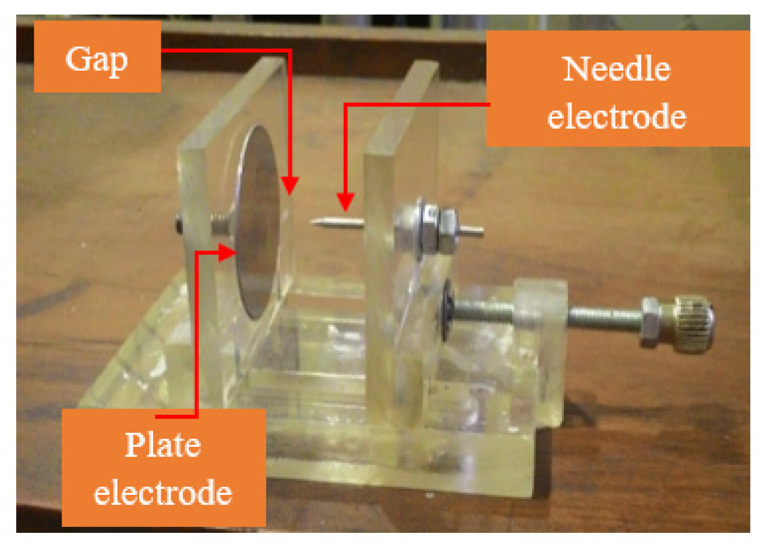
Two types of test objects able to create different types of PD, namely corona and surface discharges, were enclosed in the transformer tank, see Figure 4 and Figure 5. Corona was generated by a needle-plate electrode configuration able to generate corona discharge in oil, Figure 4.
The needle (connected to HV) has a length of 5cm and a diameter of 2mm, with curvature radius of 10μm and curvature angle of 30o, while the plate electrode (connected to the grounded tank wall) has15 mm radius. The needle tip and plate electrode are separated by a gap distance of 1cm.
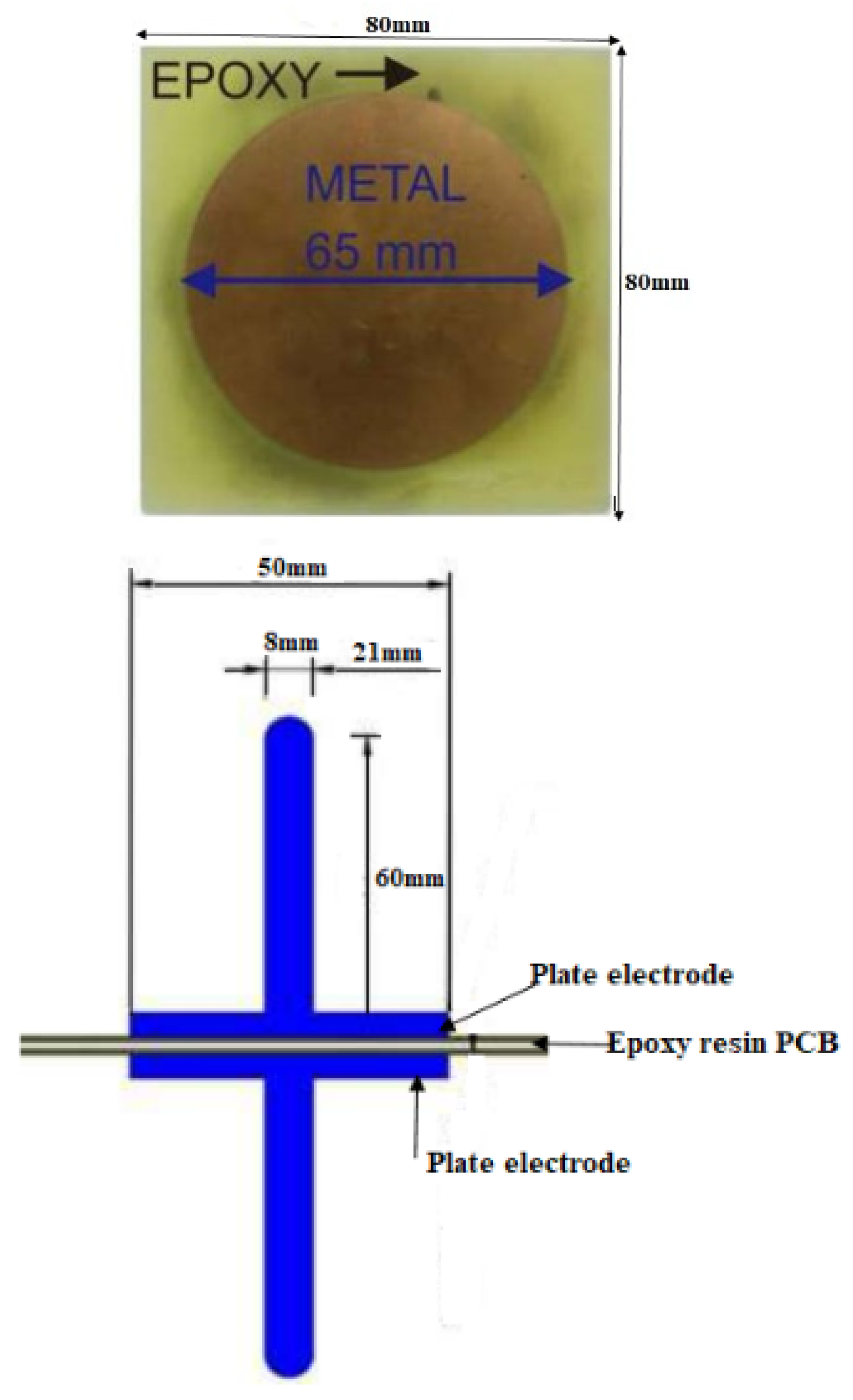
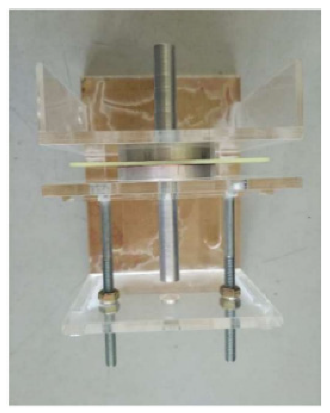
An epoxy resin specimen (whose dimensions is 80mm x 80mm x 1.6mm) was fixed between the two cylindrical plate electrodes to generate surface discharge in oil. A copper foil of 80 mm diameter and 0.035mm thickness was used to partially cover the surface of epoxy resin, in order to generate a highly-divergent field at the triple point consisting of the interface among copper foil border, oil and epoxy specimen surface. Epoxy resin and copper foil specimen were fixed between two cylindrical steel plates electrodes 65mm in diameter and 5 mm thick, one of those connected to the high voltage and the other to the grounded tank wall.

3.2. PD Measurement Set-Up

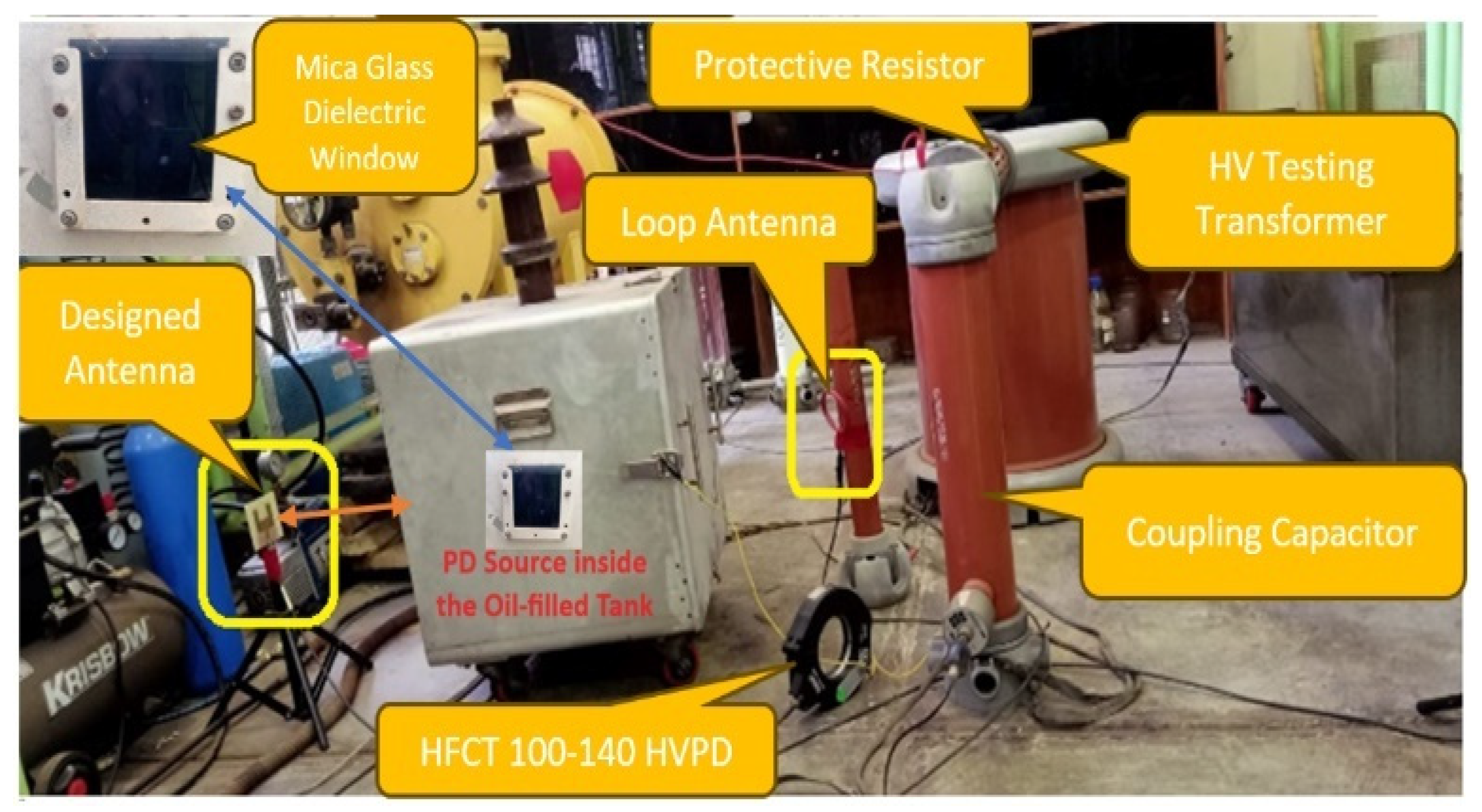
Figure 6 depicts the experimental set-up for PD measurements on the oil-filled transformer tank model using the proposed planar rectangular microstrip antenna. The PD measurement circuit used in the experiment consists of a 100kV-5kVA high voltage testing transformer, a 6100-Ohm protective resistor, a 100pF coupling capacitor, a 40nF voltage divider capacitor, 0-220VAC voltage regulator, designed UHF planar antenna, commercial high-frequency current transformer, HFCT sensor (connected between tank and ground, bandwidth 10 kHz-20 MHz), PD-source test object (needle-plate electrode and plate-plate electrode), digital storage oscilloscope (DSO) and coaxial cables connecting the PD sensors to the oscilloscope.
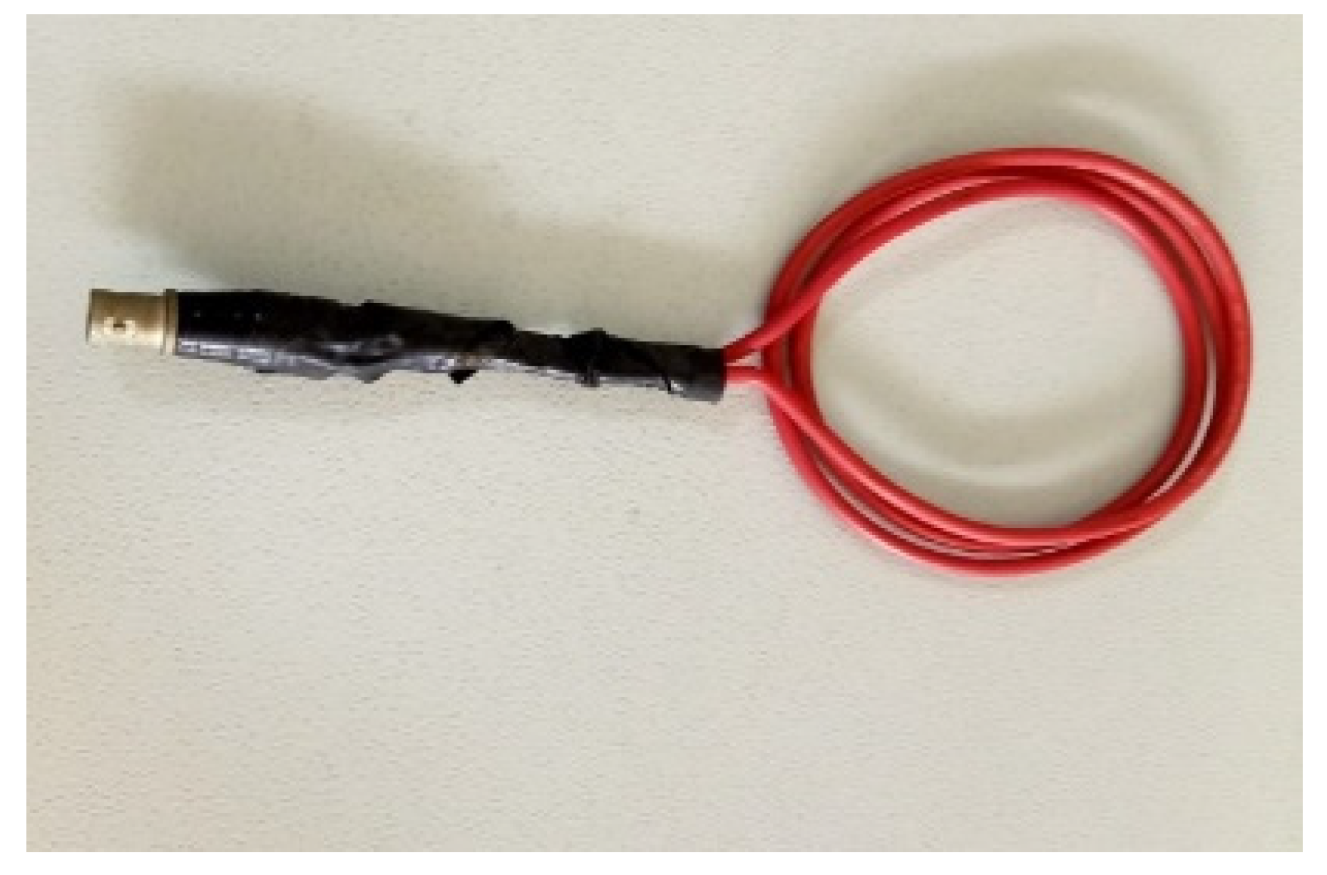
The PD measurement circuit used in the experiment consists of a 100kV-5kVA high voltage testing transformer, a 6100-Ohm protective resistor, a 100pF coupling capacitor, a 40nF voltage divider capacitor, 0-220VAC voltage regulator, designed UHF planar antenna, commercial high-frequency current transformer, HFCT sensor (connected between tank and ground, bandwidth 10 kHz-20 MHz), PD-source test object (needle-plate electrode and plate-plate electrode), digital storage oscilloscope (DSO) and coaxial cables connecting the PD sensors to the oscilloscope. A personal computer connected to the DSO was used to store PD measurement data. A further sensor was used for comparison with the proposed one, is a loop antenna having a diameter of 80 mm and 3 turns, see Figure 7.

4. PD Measurement and Results Discussion

4.1. Breakdown Voltage Measurement

To optimize the test voltages and for the sake of safety of operators and used instrumentation, the breakdown voltage (BDV) was measured before choosing the test voltage values to be applied for both surface and corona discharge measurements. Supply voltage was increased in step of 1kV/s until the breakdown occurred. The BDV test was repeated five times to obtain the average BDV value, which was found to be 22kV for the surface discharge cell and 18 kV for the corona discharge test objects submerged in transformer oil(mineral oil). Thus, the test voltage levels for PD measurements were chosen to be 10kV, 12kV, 14kV and 16kV for both surface and corona discharges tests.

4.2. Ambient Noise Measurement

Since the ambient noise in laboratory environment can affect PD detection sensitivity, before starting PD measurement experiments, the level of background noise was measured beforehand. In this scenario, 20 data samples for background noise measurement were collected, where the average noise values detected by the planar rectangular microstrip antenna, loop antenna and HFCT sensor were found to be 8.8mV, 9.6mV and 8.2mV, respectively, which established the oscilloscope trigger level for PD acquisition. A wavelet-transform software package was used during data processing to filter out the high-level noise exceeding the oscilloscope trigger level, such as transient noise caused by switching operations [27].

4.3. Surface and Corona Discharge Inception Voltage Measurements

To verify the antenna sensitivity capability in detecting electromagnetic waves induced by PD activity inside the oil-filled metal tank, the partial discharge inception voltage (PDIV) was measured by gradually increasing the applied voltage until PD pulse activity steadily appears on the oscilloscope. For the case of surface discharges on the PCB substrate, the mean surface partial discharge inception voltage (SPDIV) in transformer oil was measured to be 9.5kV, 9.7kV and 10kV for the proposed planar rectangular microstrip antenna, loop antenna and HFCT sensor, respectively. On the other hand, in the case of corona, the mean corona discharge inception voltage (CDIV) in transformer oil was 7.4kV, 7.6kV and 7.9kV for the proposed planar rectangular microstrip antenna, loop antenna and HFCT sensor, respectively. It is thus confirmed that the designed planar rectangular microstrip antenna was able to detect surface discharge and corona discharge signals at slightly lower applied voltage compared to the loop antenna and HFCT sensor, thus indicating better PD detection sensitivity for the proposed planar rectangular microstrip antenna. For both SPDIV and CDIV measurements, the proposed planar rectangular microstrip antenna and loop antenna were positioned at 50cm from the oil tank.

4.4. PD Waveforms and Frequency Spectra

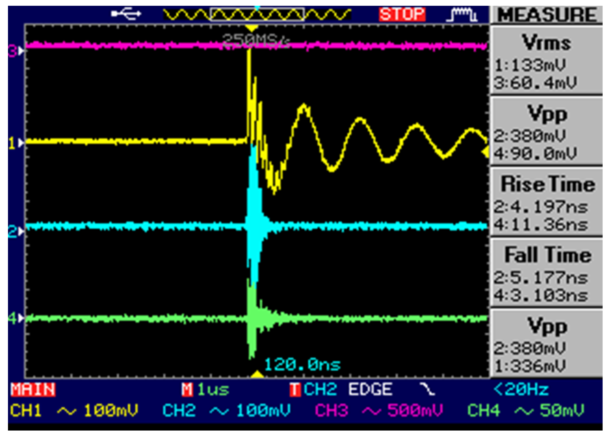
Figure 8 shows the oscilloscope screenshot for typical surface PD waveforms detected at 10kV simultaneously by the commercial HFCT (yellow color), proposed planar rectangular antenna (light blue color) and loop antenna (green color). These sensors are connected to different channels on the digital oscilloscope. The planar rectangular microstrip antenna, connected to channel 2, detected PD signals with peak-to-peak (Vpp) magnitude= 380mV, while for the loop antenna, connected to channel 4, detected PD signals whose magnitude Vpp= 90mV and for the HFCT, connected to channel 1, detected PD signals whose magnitude Vpp= 336mV. Thus, based on these PD waveforms measurement results, it is seen that the proposed planar rectangular antenna records PD signals with higher magnitude compared to those detected by the loop antenna and the HFCT sensor.
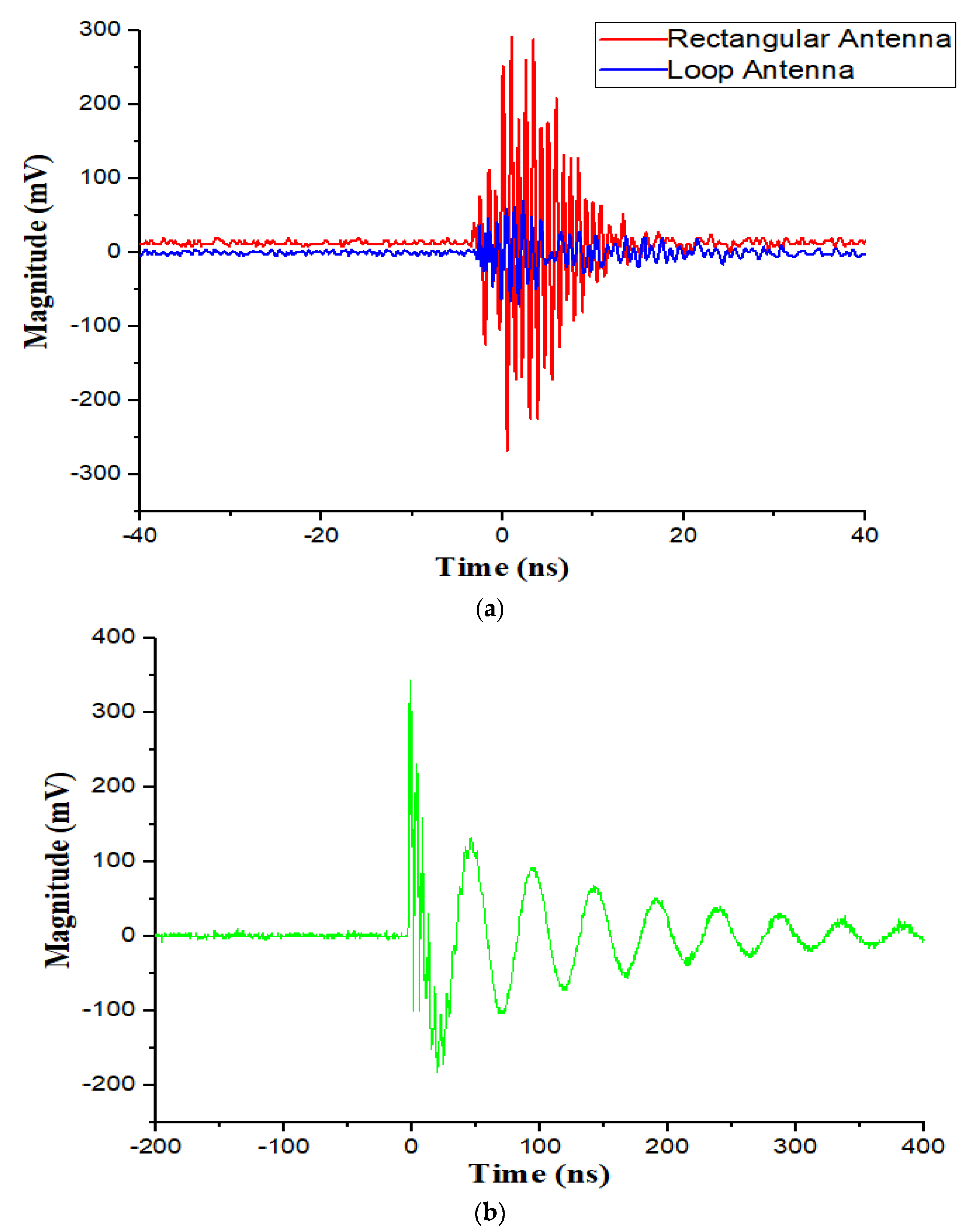
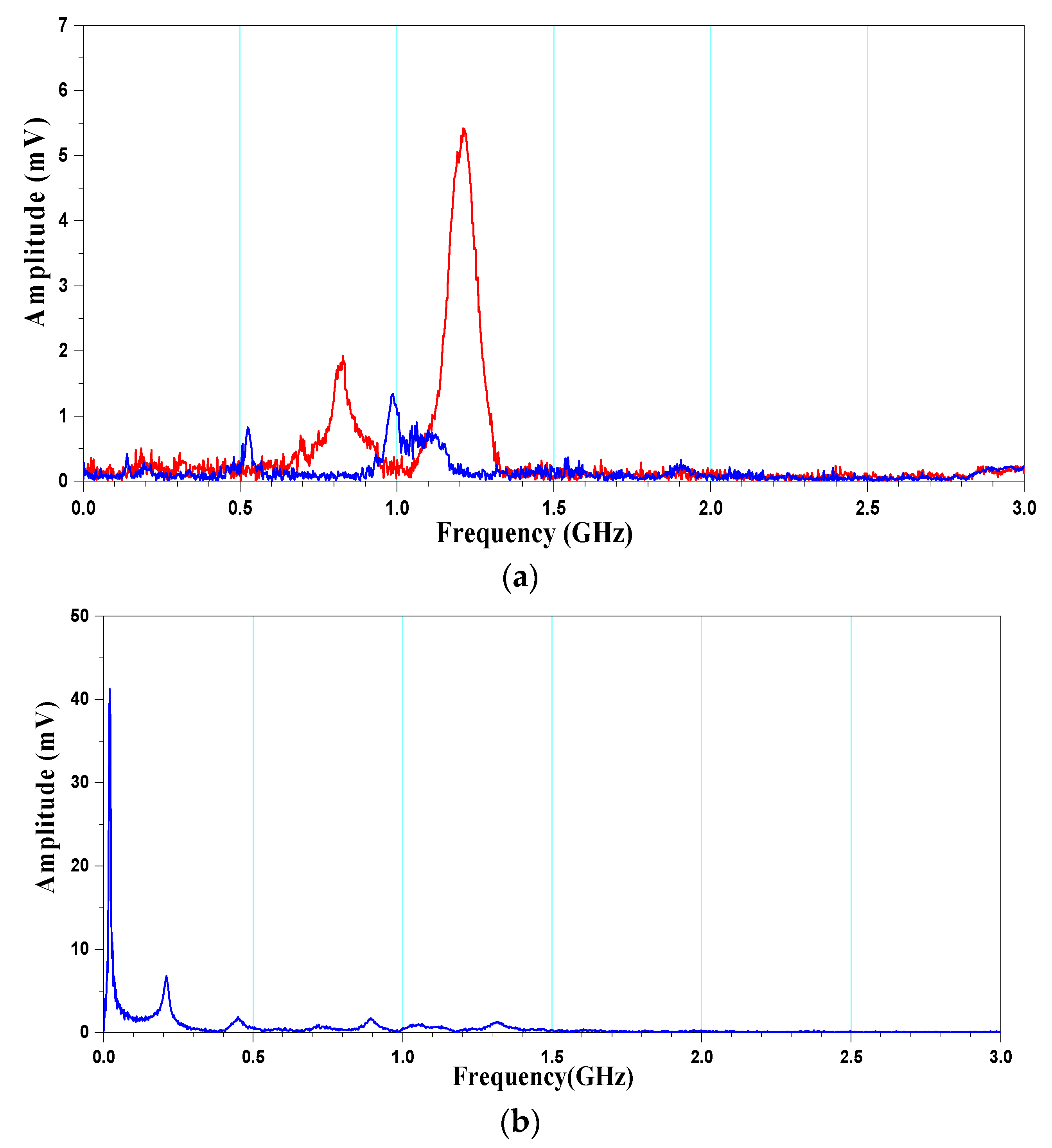
Figure 9 shows examples of the processed waveform for surface PD detected at 16 kV by the designed planar rectangular antenna simultaneously with the loop antenna (a) and HFCT (b). Both antennas captured the PD-induced signals when they were positioned at distance of 50 cm from the transformer tank wall containing PD source. Frequency spectra of surface PD signals detected by the proposed planar rectangular microstrip antenna, loop antenna and the HFCT sensor are shown in Figure 10. It can be seen that the frequency component of surface PD signals detected by both antennas ranges from 0.1GHz to 1.5GHz, with the dominant frequency at 1.2GHz and 1.0 GHz for rectangular antenna and a loop antenna, respectively. Conversely, the dominant frequency for surface PD detected by HFCT sensor is around 19MHz.
Therefore, the proposed planar rectangular antenna can likely detect PD signals with higher magnitude than for loop antenna, both in time and frequency domain. Table 2 summarizes these findings, referring to surface PD signals and various test voltage levels. It is seen that amplitude of PD signals increases with voltage and that the proposed rectangular microstrip antenna has higher sensitivity than the loop antenna and HFCT sensors. It noteworthy that during all these experiments both antennas were placed at 50cm in parallel to the oil-filled transformer tank model.

4.5. PRPS and PRPD Patterns for Corona Discharge in Oil Insulation

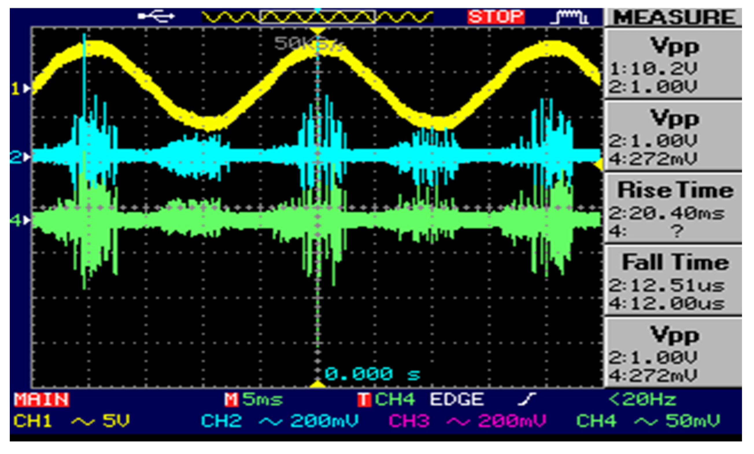
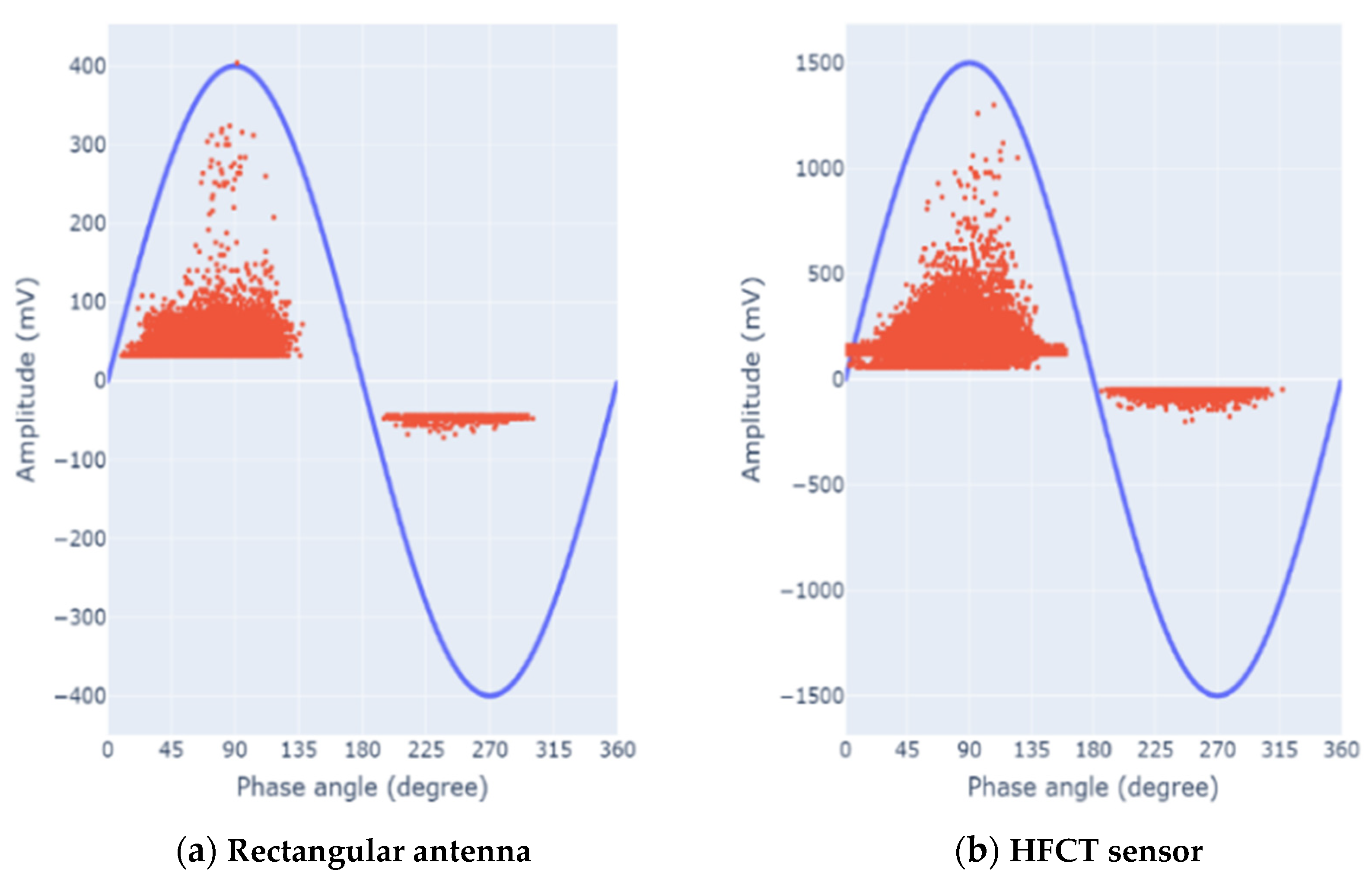
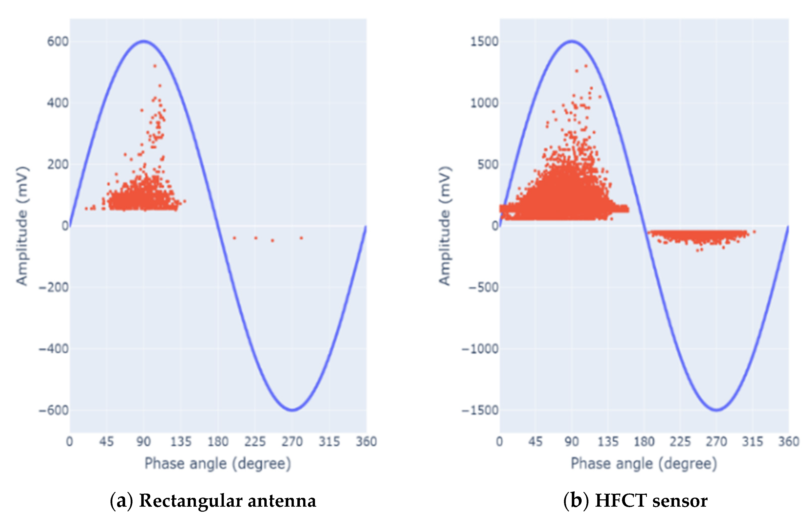
Figure 11 depicts a typical phase resolved pulse sequence (PRPS) of corona discharges detected by the designed rectangular microstrip antenna over consecutive 5 cycles of the AC voltage, in comparison with the PRPS obtained from commercial HFCT sensor, at test voltage of 12kV, when the antenna was positioned at a distance of 50cm from the tank wall. As expected for corona discharge, it can be seen that the PD pulses are concentrated around the peak of applied AC voltage, around 900 and 2700 in positive and negative half-cycle, respectively. It is noteworthy that PD pulses are larger in positive than in negative half cycles.
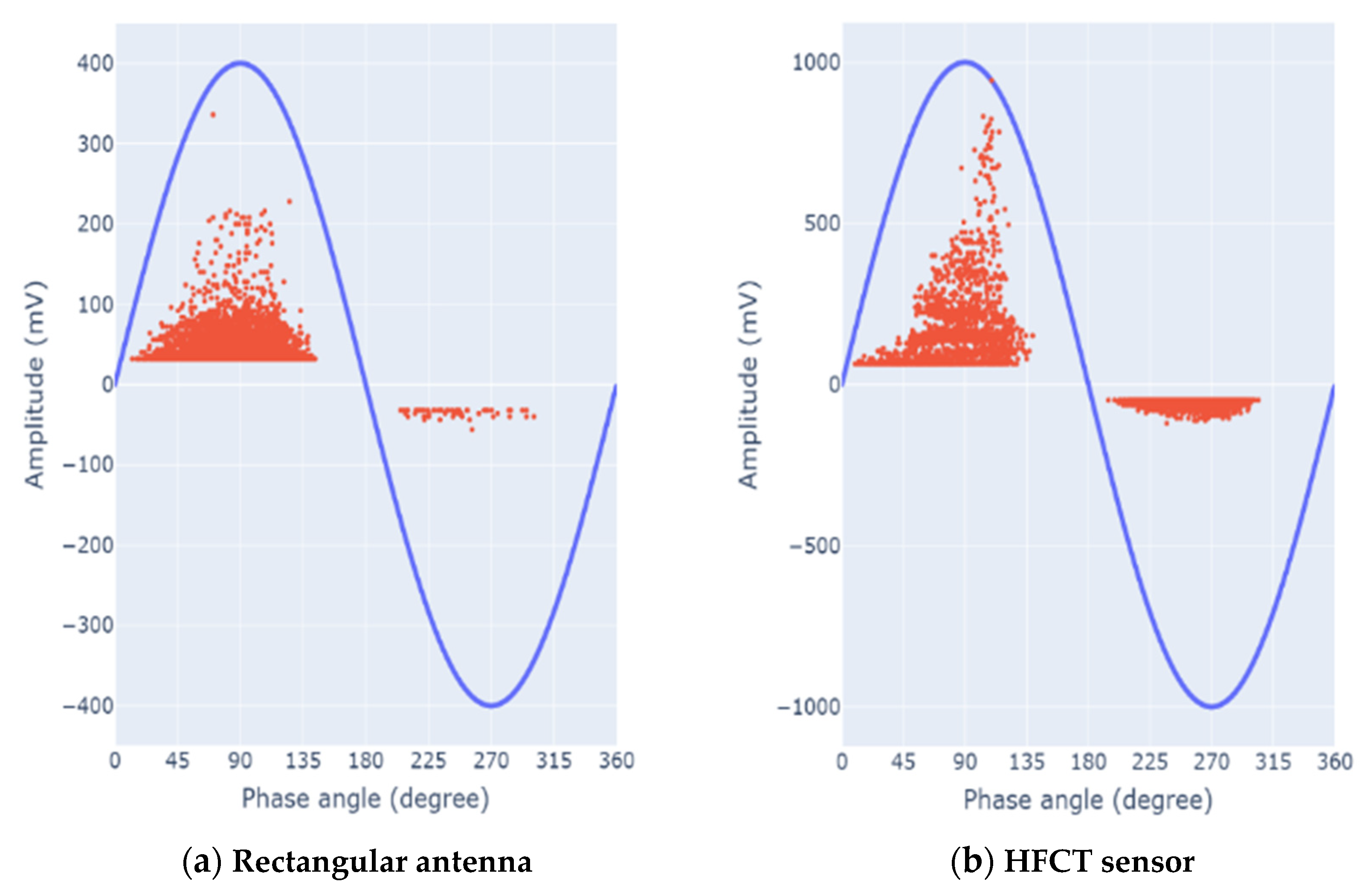
Figure 12, Figure 13 and Figure 14 display typical phase resolved partial discharge (PRPD) patterns detected by the designed rectangular microstrip antenna and the commercial HFCT sensor, at various applied voltages. As expected, it is seen that the rectangular antenna provides PRPD patterns similar to those obtained by the HFCT sensor. PD pulses confirm to have higher repetition rate and magnitude in positive than in negative half-cycle, and they are concentrated at phase angles around 900 and 2700 of the AC applied voltage [28,29]. It is worth mention that by increasing the applied voltage, PD repetition rate and amplitude detected by all sensors also increase.
In conclusion, the PRPS and PRPD patterns results presented in Figure 11, Figure 12, Figure 13 and Figure 14 for the designed rectangular microstrip antenna and the commercial HFCT sensor indicated that both sensors can provide the same analysis and diagnostic signature, so that experts in PD diagnostic and analysis could easily identify these patterns to come from corona discharge [30,31,32,33].

4. Conclusions

This paper investigates the performance of a novel and cost effective planar rectangular microstrip antenna that can be used for partial discharge monitoring on high voltage (HV) and medium voltage (MV) power assets. The proposed rectangular antenna has a compact size (80mm x 70mm x 1.6mm) and it can be fabricated on a common PCB FR-4, readily available at the market. It has low return loss, voltage standing wave ratio, wide bandwidth, and high gain, enabling high-sensitivity PD acquisition.
To validate the sensitivity performance of the proposed planar rectangular microstrip antenna in detecting PD pulses emitted by two types of insulation defects, namely corona discharge and surface discharges in oil insulation, the commercial HFCT sensor was used as a comparison PD sensor. Comparing its performance with other sensors, namely a loop antenna and a commercial HFCT, through surface and corona discharge measurements generated in artificial defects inside an oil-filled transformer tank, it is shown that the proposed antenna has a high sensitivity and signal-to-noise ratio (SNR) in detecting both surface and corona PDs.
In addition, based on the PRPD patterns results, it was seen that the proposed planar rectangular microstrip antenna can identify the type of insulation defects in the same manner as the commercial HFCT sensor, which can assist in PD source localization.
It can be concluded that the proposed planar rectangular microstrip antenna could be a simple, cheap, compact, and effective suitable candidate sensor for PD detection and monitoring of HV and/or MV power system components, when irradiated PD signals can be available through internal or external sensor location.

Author Contributions

Writing, J.P.U., S. and U.K.; laboratory tests, J.P.U., S. and U.K.; methodolog, J.P.U., U.K. and G.C.M.; writing—review and editing, G.C.M. and S.; supervision, S. and G.C.M.; conceptualization, U.K, S. and G.M.C. All authors have read and agreed to the published version of the manuscript.

Funding

This research received no external funding.

Data Availability Statement

The data presented in this study are available on request from the corresponding author.

Acknowledgments

This research was supported by Institut Teknologi Bandung.

Conflicts of Interest

The authors declare no conflict of interest.

References

  1. Naderiallaf, H.; Seri, P.; Montanari, G.C. Designing a HVDC Insulation System to Endure Electrical and Thermal Stresses Under Operation. Part I: Partial Discharge Magnitude and Repetition Rate During Transients and in DC Steady State. IEEE Access 2021, 9, 35730–35739. [Google Scholar] [CrossRef]
  2. Dai, X.; Hao, J.; Montanari, G.C.; Jian, Z.; Liao, R.; Zheng, X. Influence of thermal ageing on high-field polarization characteristics and conductivity behavior of submarine polymeric cables insulation. High Voltage 2023, 8, 138–148. [Google Scholar] [CrossRef]
  3. Besharatifard, H.; Hasanzadeh, S.; HeydarianForushani, E.; Alhelou, H.H.; Siano, P. Detection and Analysis of Partial Discharges in Oil-Immersed Power Transformers Using Low-Cost Acoustic Sensors. Appl. Sci. 2022, 12, 3010. [Google Scholar] [CrossRef]
  4. Santosh Kumar, A.; Gupta, R.P.; Udayakumar, K.; Venkatasam, A. Online Partial Discharge Detection and Location Techniques for Condition Monitoring of Power Transformers: A Review. In Proceedings of the 2008 International Conference on Condition Monitoring and Diagnosis, Beijing, China, 21–24 April 2008. [Google Scholar]
  5. Sikorski, W.; Walczak, K.; Gil, W.; Szymczak, C. On-Line Partial Discharge Monitoring System for Power Transformers Based on the Simultaneous Detection of High Frequency, Ultra-High Frequency, and Acoustic Emission Signals. Energies 2020, 13, 327. [Google Scholar] [CrossRef]
  6. Gulski, E.; Wojciech, K.; Ariaans, T.H.P.; Behrmann, G.; Jongen, R.; Garnacho, F.; Kornhuber, S.; Ohtsuka, S.; Petzold, F.; Sánchez-Urán, M.A.; Siodła, K.; Tenbohlen, S. Guidelines for partial discharge detection using conventional (IEC 60270) and unconventional methods (2016).
  7. Azam, S.M.K.; Othman, M.; Illias, H.A.; Abdul Latef, T.; Tariqul Islam, M.; Fadzil Ain, M. Ultra-high frequency printable antennas for partial discharge diagnostics in high voltage equipment. Alexandria Engineering Journal 2023, 64, 709–729. [Google Scholar] [CrossRef]
  8. Tenbohlen, S.; Beura, C.P.; Sikorski, W.; Albarracín Sánchez, R.; de Castro, B.A.; Beltle, M.; Fehlmann, P.; Judd, M.; Werner, F.; Siegel, M. Frequency Range of UHF PD Measurements in Power Transformers. Energies 2023, 16, 1395. [Google Scholar] [CrossRef]
  9. Xavier, G.V.R.; de Oliveira, A.C.; Silva, A.D.C.; Nobrega, L.A.M.M.; da Costa, E.G.; Serres, A.J.R. Application of Time Difference of Arrival Methods in the Localization of Partial Discharge Sources Detected Using Bio-Inspired UHF Sensors. IEEE Sensors Journal 2021, 21, 1947–1956. [Google Scholar] [CrossRef]
  10. Coenen, S.; Tenbohlen, S. Location of PD Sources in Power Transformers by UHF and Acoustic Measurements. IEEE Trans. Dielectr. Electr. Insul. 2012, 19, 1934–1940. [Google Scholar] [CrossRef]
  11. Zhang, S.; Zhang, G.; Lu, C.; Tian, H.; Liu, J.; Zhang, X. Flexible Planar Monopole Built-in GIS PD Sensor Based on Meandering Technology. Sensors 2022, 22, 4134. [Google Scholar] [CrossRef] [PubMed]
  12. Zhang, H.; Zhang, G.; Zhang, X.; Tian, H.; Lu, C.; Liu, J.; Zhang, Y. PD Flexible Built-In High-Sensitivity Elliptical Monopole Antenna Sensor. Sensors 2022, 22, 4982. [Google Scholar] [CrossRef]
  13. Judd, M.D.; Farish, O.; Pearson, J.S.; Hampton, B.F. Dielectric windows for UHF partial discharge detection. IEEE Trans. Dielectr. Electr. Insul. 2001, 8, 953–958. [Google Scholar] [CrossRef]
  14. Judd, M.D.; Yang, L.; Hunter, I.B.B. Partial discharge monitoring of power transformers using UHF sensors. Part I: sensors and signal interpretation. IEEE Electr Insul Magaz. 2005, 21, 5–14. [Google Scholar] [CrossRef]
  15. Zahed, A.A.; El-Hag, A.H.; Qaddoumi, N.; Hussein, R.; Shaban, K.B. Comparison of different fourth order Hilbert fractal antennas for partial discharge measurement. IEEE Trans. Dielectr. Electr. Insul. 2017, 24, 175–182. [Google Scholar] [CrossRef]
  16. Yadam, Y.R.; Sarathi, R.; Arunachalam, K. Planar Ultrawideband Circularly Polarized Cosine Slot Archimedean Spiral Antenna for Partial Discharge Detection. IEEE Access 2022, 10, 35701–35711. [Google Scholar] [CrossRef]
  17. Qi, Y.; Yang, F.; Gao, B.; Ran, J.; Wang, S.; Shen, W.; Ammad, J. Design of Ultra-Wide Band Metal-Mountable Antenna for UHF Partial Discharge Detection. IEEE Access 2019, 7, 60163–60170. [Google Scholar] [CrossRef]
  18. Uwiringiyimana, J.P.; Khayam, U.; Suwarno; Montanari, G.C. Comparative Analysis of Partial Discharge Detection Features Using a UHF Antenna and Conventional HFCT Sensor. IEEE Access 2022, 10, 107214–107226. [Google Scholar] [CrossRef]
  19. Azam, S.M.K.; Othman, M.; Hazlee, A.I.; Tarik, A.L.; Wan, N.L.M.; Daniar, F.; Hossain Zakir, A.K.M.; Mohd, F.A. Planar Sensor for Noise Cancellation During Partial Discharge Detection in Open Substation. IEEE Sensors Journal 2023, 23, 15552–15562. [Google Scholar] [CrossRef]
  20. Chai, H.; Phung, B.T.; Zhang, D. Development of UHF Sensors for Partial Discharge Detection in Power Transformer. In Proceedings of the 2018 International Conference on Condition Monitoring and Diagnosis, Perth, WA, Australia; 2018; pp. 1–5. [Google Scholar]
  21. Nobrega, L.A.M.M.; Xavier, G.V.R.; Aquino, M.V.D.; Serres, A.J.R.; Albuquerque, C.C.R.; Costa, E.G. Design and development of a bio-inspired UHF sensor for partial discharge detection in power transformers. Sensors 2019, 19, 653. [Google Scholar] [CrossRef]
  22. Xavier, G.V.R.; da Costa, E.G.; Serres, A.J.R.; Nobrega, L.A.M.M.; Oliveira, A.C.; Sousa, H.F.S. Design and application of a circular printed monopole antenna in partial discharge detection. IEEE Sensors Journal 2019, 19, 3718–3725. [Google Scholar] [CrossRef]
  23. Uwiringiyimana, J.P.; Khayam, U. Design and application of double layer bowtie antenna and single layer bowtie antenna as UHF sensors for partial discharge detection. IOP Conf. Ser.: Mater. Sci. Eng. 2020; 850, 012036. [Google Scholar] [CrossRef]
  24. Rozi, F.; Khayam, U. Development of Loop Antennas for Partial Discharge Detection. Int. Journ Electr. Eng.and Inform. 2015, 7, 29–41. [Google Scholar] [CrossRef]
  25. Yang, F.; Peng, C.; Yang, Q.; Luo, H.; Ullah, I.; Yang, Y. An UWB Printed Antenna for Partial Discharge UHF Detection in High Voltage Switchgears. Progress In Electromagnetics Research C 2016, 69, 105–114. [Google Scholar] [CrossRef]
  26. Uwiringiyimana, J.P.; Suwarno; Khayam, U. Design of a Rectangular Microstrip Patch Antenna as UHF Sensor for Partial Discharge Detection on Power Transformer. In Proceedings of the 2021 3rd International Conference on High Voltage Engineering and Power Systems (ICHVEPS), Bandung, Indonesia, Bandung, Indonesia, 5–6 October 2021; pp. 563–568.
  27. Zhang, H.; Blackburn, T.R.; Phung, B.T.; Sen, D. A novel wavelet transform technique for on-line partial discharge measurements. 2. On-site noise rejection application. IEEE Trans. Dielectr. Electr. Insul. 2007, 14, 15–22. [Google Scholar] [CrossRef]
  28. Suwarno, D. A Model and Computer Simulation of Partial Discharges in High Voltage Liquid Insulation. In Proceedings of the 2010 Fourth Asia International Conference on Mathematical/Analytical Modelling and Computer Simulation, Kota Kinabalu, Malaysia, 26–28 May 2010; pp. 444–449. [Google Scholar]
  29. Swati, K.; Yadav, K.S.; Sarathi, R.; Vinu, R.; Danikas, M.G. Understanding Corona discharge activity in titania nanoparticles dispersed in transformer oil under AC and DC voltages. IEEE Trans. Dielectr. Electr. Insul. 2017, 24, 2325–2336. [Google Scholar] [CrossRef]
  30. Sun, J.; Li, X.; Zhu, L.; Ji, S.; Cui, Y. Partial discharge of needle-plane defect in oil-paper insulation under AC and DC combined voltages: Developing processes and characteristics. Energies 2017, 10, 1759. [Google Scholar] [CrossRef]
  31. Rodrigo Mor, A.; Castro Heredia, L.; Harmsen, D.; Muñoz, F. A new design of a test platform for testing multiple partial discharge sources. Int. J. Electr. Power Energy Syst. 2018, 94, 374–384. [Google Scholar] [CrossRef]
  32. Zhang, C.; Dong, M.; Ren, M.; Huang, W.; Zhou, J.; Gao, X.; Albarracín, R. Partial discharge monitoring on metal-enclosed switchgear with distributed non-contact sensors. Sensors 2018, 18, 551. [Google Scholar] [CrossRef]
  33. Kang, A.; Tian, M.; Li, C.; Song, J.; Suraci, S.V.; Li, W.; Lin, L.; Lei, Z.; Fabiani, D. Development and pattern identification of end-winding discharge under effect of relative humidity and temperature for HV motors. High Voltage 2020, 5, 434–443. [Google Scholar] [CrossRef]
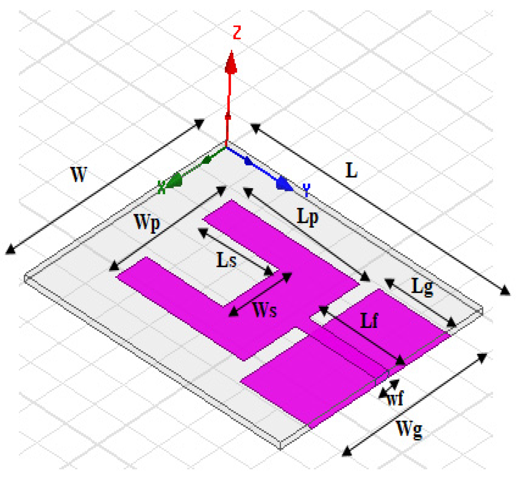
Figure 1. Geometrical view of the proposed planar rectangular microstrip antenna.
Preprints 110360 g001
Figure 2. Fabricated planar rectangular microstrip antenna: (a) Front view showing radiating patch, (b) back view showing the ground plane.
Preprints 110360 g002
Figure 3. Simulated and measured (a) return loss and (b) VSWR for the proposed planar rectangular microstrip antenna.
Preprints 110360 g003
Figure 4. Needle-plate electrode model for corona discharge generation.
Preprints 110360 g004
Figure 5. Plate-plate electrode model with epoxy resin PCB insulator for surface discharge generation.
Preprints 110360 g005aPreprints 110360 g005b
Figure 6. Experimental set-up for PD detection on oil-filled transformer tank model by using the designed rectangular microstrip antenna and loop antenna simultaneously with a HFCT sensor.
Preprints 110360 g006
Figure 7. Loop antenna sensor.
Preprints 110360 g007
Figure 8. Oscilloscope screenshot for typical surface PD signals waveforms detected by the planar rectangular microstrip antenna (light blue color), a loop antenna (green color), and a HFCT sensor (yellow color), with both antennas positioned at 50cm in parallel to the tank wall, at the applied voltage of 10kV.
Preprints 110360 g008
Figure 9. Processed waveforms for surface PD signals detected by (a) planar rectangular microstrip antenna (red color) and a loop antenna (blue color), and (b) HFCT sensor (green color), when both antennas were positioned at 50cm in parallel to the tank wall, at the applied voltage of 16kV.
Preprints 110360 g009
Figure 10. Frequency spectrum of surface PD signals detected by (a) planar rectangular microstrip antenna (red color) and loop antenna (blue color) placed at a distance of 50cm parallel to the tank wall (b) Frequency spectrum of surface PD detected by HFCT; applied voltage was 16kV.
Preprints 110360 g010
Figure 11. Typical PRPS for corona discharge detected on oil-filled transformer tank by using the designed planar rectangular microstrip antenna (green color trace with a Vpp=272mV) and HFCT sensor (light blue color trace with a Vpp=1V) at 12kV.Reference AC applied voltage is indicated in yellow color trace.
Preprints 110360 g011
Figure 12. PRPD patterns for corona discharge detected on oil-filled transformer tank model by the designed planar rectangular microstrip antenna and the commercial HFCT sensor at 12kV.
Preprints 110360 g012
Figure 13. PRPD patterns for corona discharge detected on oil-filled transformer tank model by the designed planar rectangular microstrip antenna and the commercial HFCT sensor at 14kV.
Preprints 110360 g013
Figure 14. PRPD patterns for corona discharge detected on oil-filled transformer tank model by the designed planar rectangular microstrip antenna and the commercial HFCT sensor at 16kV.
Preprints 110360 g014
Table 1. Comparison between simulation and measurement results for the proposed planar rectangular microstrip antenna.
Antenna characteristic parameters Simulation results Measurement results
Return loss, RL1 (dB) -48 -31.6
Return Loss, RL2 (dB) -37 -26.8
Fresonance 1 (GHz) 1.55 1.63
Fresonance2 (GHz) 2.3 2.26
Total Bandwidth 1.37GHz-2.61GHz胡瑾(1.24GHz) 1.44GHz-2.59GHz胡瑾(1.15GHz)
VSWR1 1.01 1.06
VSWR2 1.03 1.09
Table 2. Comparison between surface PD signal amplitudes detected by the proposed rectangular microstrip antenna, loop antenna and HFCT sensor at various applied test voltages.
Antenna and HFCT Sensor Position Applied Voltage
Voltage level
10kV 12kV 14kV 16kV
Surface PD signal amplitude (peak-to-peak voltage) detected by rectangular antenna placed at 50cm from the tank wall 380mV 404mV 488mV 560mV
Surface PD signal amplitude (peak-to-peak voltage) detected by loop antenna placed at 50cm from the tank wall 90mV 94mV 116mV 140mV
Surface PD signal amplitude (Peak-to-peak Voltage) detected by the commercial HFCT sensor clamped across ground wire 336mV 376mV 484mV 528mV
Disclaimer/Publisher’s Note: The statements, opinions and data contained in all publications are solely those of the individual author(s) and contributor(s) and not of MDPI and/or the editor(s). MDPI and/or the editor(s) disclaim responsibility for any injury to people or property resulting from any ideas, methods, instructions or products referred to in the content.
Copyright: This open access article is published under a Creative Commons CC BY 4.0 license, which permit the free download, distribution, and reuse, provided that the author and preprint are cited in any reuse.
Prerpints.org logo

Preprints.org is a free preprint server supported by MDPI in Basel, Switzerland.

Subscribe

© 2024 MDPI (Basel, Switzerland) unless otherwise stated