1. Introduction
Rocks play an increasingly critical role in construction, particularly in environments subjected to high loading rates and confining pressures. They serve as structural elements or aggregates in ceramic and cementitious matrices. Understanding their physical and mechanical properties is essential. Demand for stone aggregates near urban centers accelerates quarry exploitation near city peripheries. However, the lack of systematic experimentation and analysis of rock components often leads to suboptimal material use, depleting nearby quarry reserves prematurely.
Key indicators of stone quality include density (ρ), uniaxial compressive strength (UCS), and modulus of elasticity (Ed). Utilizing these parameters in deformation and displacement models helps identify optimal materials and quarry locations for efficient rock utilization based on strength characteristics. The mechanical and elastic properties of intact rock significantly influence engineering design across various sectors, from tunnels and dams to slope stability and historical building preservation [
1]. Despite the crucial role of rock properties, direct testing remains cumbersome, expensive, and time-consuming due to the requirement for high-quality core samples [
2,
3].
Rocks are characterized through physical and mechanical tests which allow for the estimation of their behavior under engineering requirements. Consequently, specific research studies estimate various parameters in rocks such as uniaxial compressive strength, static and dynamic modulus of elasticity. Additionally, some studies employ methods like finite element analysis to estimate rock behavior. For example, disconnected vesicles in extensive basalt flows significantly affects properties such as compressive strength, modulus of elasticity, Poisson’s ratio, and sonic velocities [
4].
Predictive models estimate rock parameters using data such as UCS, elasticity (E), and deformation modulus [
5,
6,
7]. These models employ artificial neural networks for predicting deformation modulus [
8]. Mechanical tests on various volcanic rocks have evaluated the relationships between chemical and mineralogical composition, microstructure, texture, and physico-mechanical properties [
9]. Numerical analyses through the finite element method have been conducted to examine different adhesives, including cyanoacrylate, polyester, epoxy-based adhesive, and Portland cement paste [
10]. Others have investigated the relationship between dynamic and static parameters using different methods for various rocks, finding that, the difference between dynamic and static elastic moduli can be attributed to microcracks and pores in the rocks [
11,
12,
13]
The coupled discrete element-finite difference method (DEM-FDM) offers a numerical framework for analyzing the load-deformation behavior of soft soils stabilized by columns [
14]. DEM estimated the elastic properties of damaged rocks [
15], while the T-matrix model has shown potential for determining effective stone moduli using the full-wave sonic (FWS) tool [
16]. Nondestructive methods have characterized stress-induced damage progression in three rock types by capturing their nonlinear elastodynamic responses [
17] and material’s behavior [
18]. Finite element methods (FEM) are used in conjunction with the software (Abaqus
®) to obtain rock parameters [
19].
Alternatively, a laboratory compression test on granite was replicated using the grain-based discrete and finite element method (FDEM). The study focused on the solid-fragile fracture process, the damage behavior resulting from initiation and cracking, propagation before maximum failure, and the dependence on intrinsic factors such as rock type, grain size, distribution, mineralogy and rock texture [
20]. Recently, the main features and capability of the field test-enriched finite element method to effectively simulate rock failure processes with different effects have been studied [
21]. Similarly, a field test enriched finite element method has been proposed to simulate crack propagation and coalescence of brittle rocks under mixed-mode loading [
22].
While existing studies provide detailed mechanical and physical property analyses, graphical representation of horizontal and vertical rock deformations remains underexplored. This study proposes a finite element method (FEM) model to visualize rock sample deformations under load, facilitating comparative analysis among quarries supplying construction materials in the city of Morelia, Michoacán, Mexico. Such detailed quarry characterization enables precise material specifications tailored for construction needs.
2. Methodology
The methodology proposed in this research, based FEM, requires critical parameters obtained from laboratory tests. These include ultrasonic pulse velocity (UPV), UCS, and density, which is an intrinsic property of the stone. In general, the proposed methodology allows for the determination of horizontal and vertical displacements of the stones, using essential laboratory test data for the proposed model.
2.1. Sampling
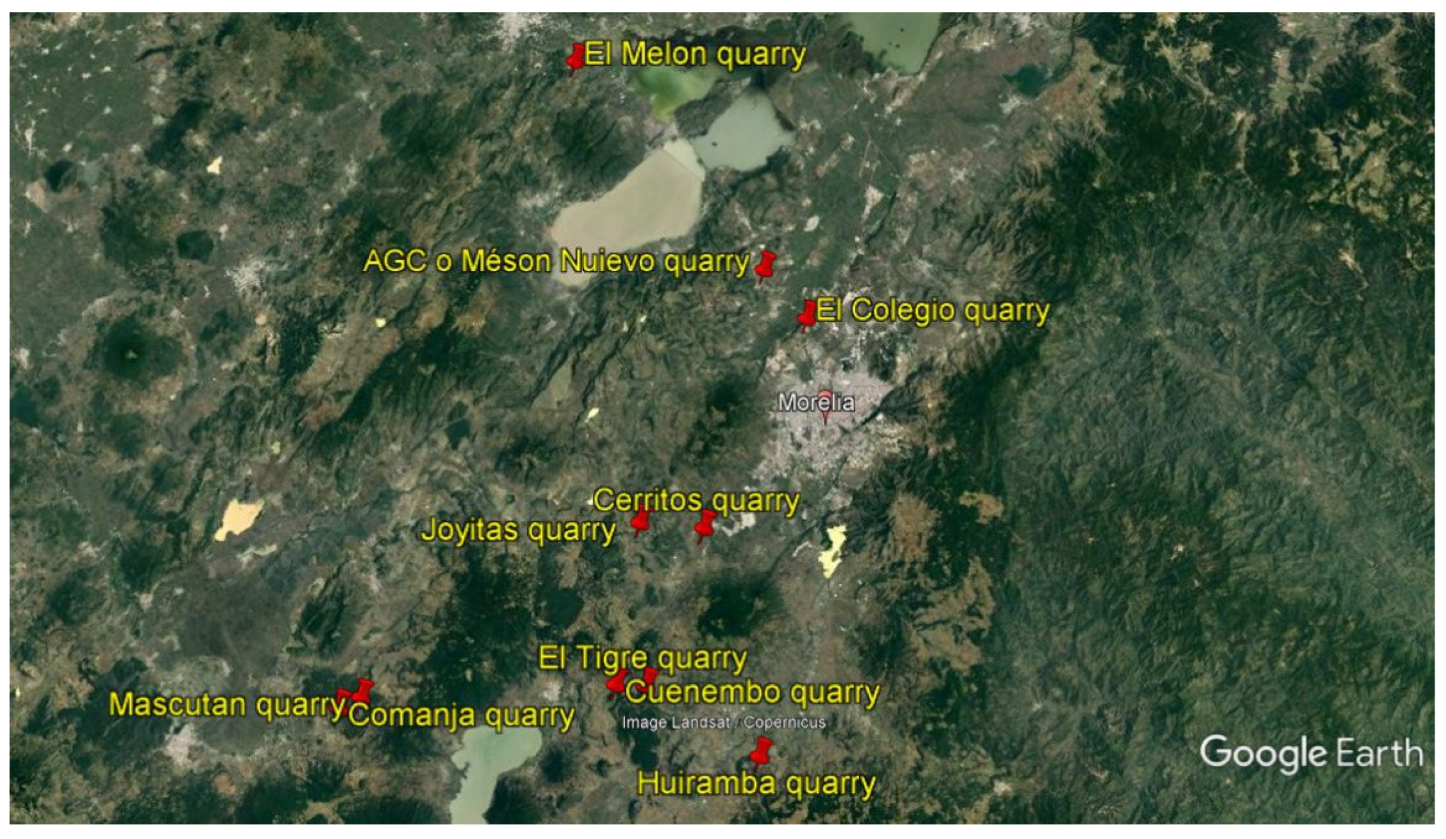
The characterized samples were obtained from 10 quarries of stone material located in the surroundings of Morelia (
Figure 1). The names of the material quarries stones, sample codes and stone types are given in
Table 1.
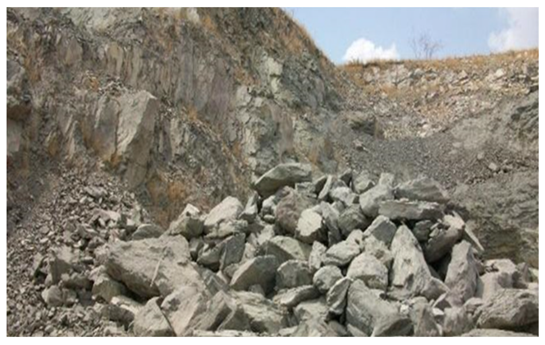
An image of the El Colegio quarry showing the stones used for crushing is shown in
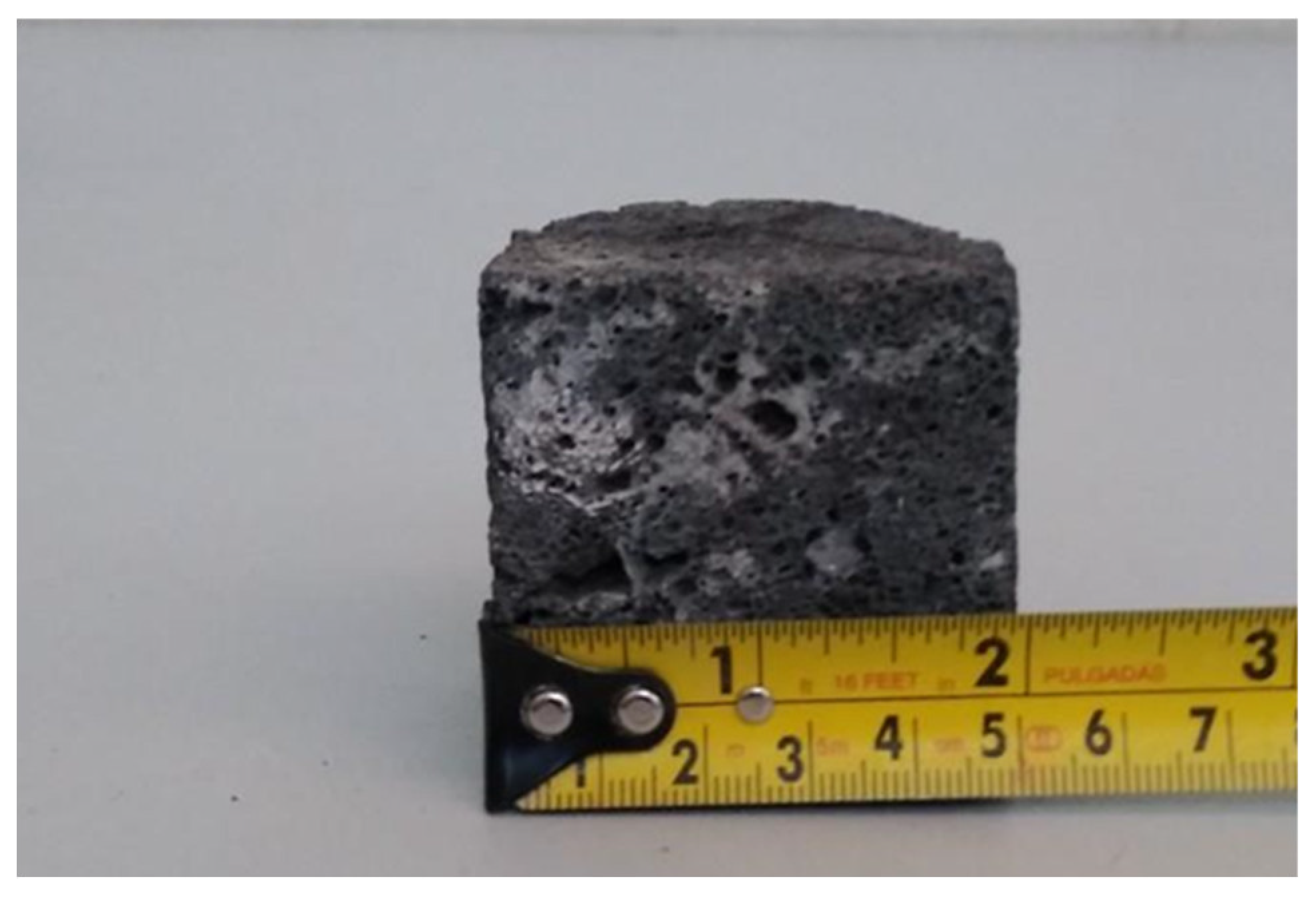
Figure 2. Samples were obtained and 11 cubes (5 x 5 x 5 cm) were cut from each quarry (
Figure 3). The cubes were used for characterization (UPV and UCS); the data obtained were used for modelling.
2.2. Characterization
Characterizations were conducted determine the structural properties of the samples. X-ray fluorescence was performed using ANDREAH equipment. SEM was performed using JEOL equipment (model JSM-6400), which has a Bruker X-ray microanalyzer, energy dispersive spectrum (EDS) and the S150A SPUTTER COATER metallizer. The X-ray diffraction was performed by means of a SIEMENS diffractometer, model D5000 X-ray diffractometers, 30 kV, 20 mA at 1.5406 Angstrom wavelength tube.
To determine the physical-mechanical properties, density (ρ) was obtained using a pycnometer, for which the sample was tagged, saturated in water for 24 hours and dried superficially before measuremen[
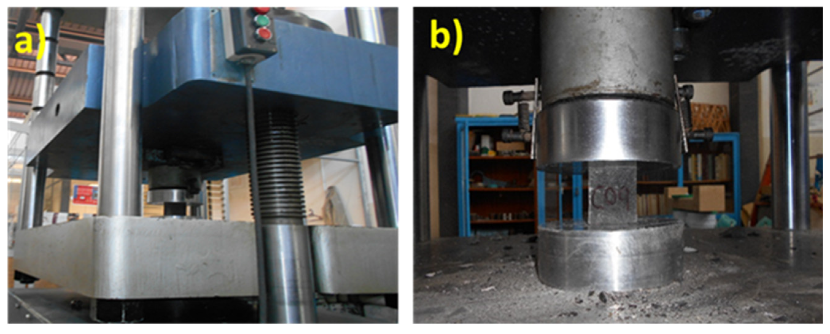
23]. UCS was assessed using the Forney universal testing machine on cubic samples (5 x 5 x 5 cm) evaluated using Equation 1.
where UCS is the uniaxial compressive strength (kgf/cm2), P is the maximum applied load (kgf) and A is the cross-sectional area (cm2). The Forney testing machine is shown in
Figure 4a and the cubic specimen is shown in
Figure 4b [
24,
25].
2.3. Determination of the Ultrasonic Pulse Velocity
In rock mechanics, ultrasonic pulse wave velocity tests are becoming increasingly common due to their non-destructive nature, speed, high precision, and low cost [
26].
The dynamic modulus of elasticity was determined by means of ultrasonic pulse velocity using the equipment (model 58E0049/B brand CONTROLS); with a frequency scale from 24 to 150kHz.
Based on ASTM D2845-08, the dynamic modulus of elasticity [
27] can be determined by means of equation 2.
Where Ed is dynamic modulus of elasticity (kg/cm2), ρ is density (kg/m3), Vs is secondary wave velocity (m/s) and Vp is primary wave velocity (m/s), based on the work of González De Vallejo and Ferrer [
28] for this type of rocks (basalt and andesite), Vs≈2/3Vp and ν≈0.25.
2.4. Modeling
For the development of this model, an almost linear behavior with local isotropy was taken, for which the governing constitutive equation was proposed (Equation 3). Transverse isotropy indicates that at each point in the rock, there is an axis of rotational symmetry. The rock exhibits isotropic properties in the plane perpendicular to this axis, known as the plane of transverse isotropy [
29]. Some researchers have studied the influence of igneous rock on seismic images, based on the wave equation that originates from Hooke’s law and Newton’s second law for isotropic, ideally elastic, heterogeneous [
30]. Additionally, other researchers have studied rock masses according to the characteristic of elastic wave propagation in the medium and the application of the elastic wave method in rock mass engineering considering a quasi-isotropic crack mass [
31]. In this research the study is performed on the rock matrix therefore it is justified to consider it isotropic as in the aforementioned researches. To estimate the horizontal and vertical displacements based on a four-node element, equations (4), (5) and (6) were used based on the references Kattan (2008), as a generalization of the rectangular four-node element [
32]. Thus, the governing constitutive equation will be given by (Equation 3).
Where σ is the stress matrix, D is the material property matrix and ϵ is the deformation matrix. For plane stresses, D takes the simple form:
Where E is the modulus of elasticity and ν is Poisson’s ratio. For the basalt and andesite samples, for ν an average value of 0.25 was taken based on reference [
28]. The isoparametric element stiffness matrix for a bilinear quadrilateral element with sides can then be written as
Where U is the vector of global nodal displacements, K is the matrix of global stiffnesses and F is the vector of global nodal forces.
To obtain the matrix K, the stiffness matrices of each element (k1, k2, k3,...kn) are assembled using Equation 6.
Where t is the thickness of the material, D is the matrix of the material properties, J is the Jacobian matrix corresponding to the transformation between the physical and computational spaces. Bi (B1, B2, B3, B4) are calculated using the bilinear quadrilateral element with natural coordinates of the following Equation [
32].
The following equation is used to obtain Bi (B1, B2, B3 and B4):
Where a, b, c, and d are calculated by the following equations
The following equation is used to calculate Ni (N1, N2, N3 and N4):
To obtain the Jacobian matrix J the following equation is used.
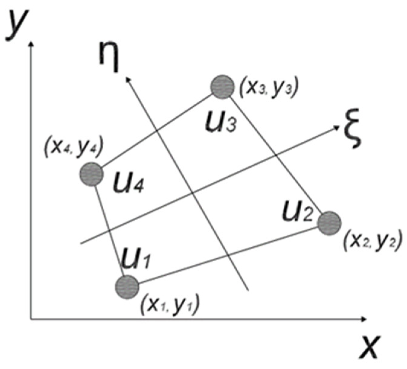
The coordinates were obtained from the bilinear element in the physical coordinate (
Figure 5).
3. Results and Discussion
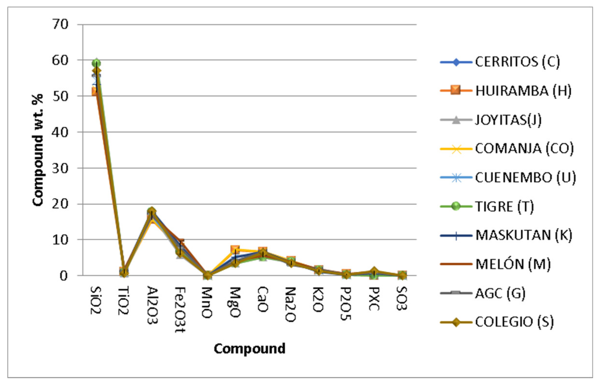
The results from the X-ray fluorescence characterization performed on all of the samples from the proposed quarries can be seen in
Figure 6. The predominant compound in all samples was SiO
2 (between 50 and 60 %) followed by Al2O
3 (20 %). All the samples present a similarity in the percentages of the compounds, no differences of compounds were observed among the materials. The importance of the above geochemical data allows the chemical classification of rocks and the understanding of the geological process using different types of diagrams. Conventionally, geochemical data used for these purposes are divided into major and trace elements. Major elements are those elements that predominate in any rock such as Si, Ti, Al, Fe, Mn, Mg, Ca, Na and K [
33,
34]. With the development of new techniques that allowed the determination of trace and ultra-trace elements, it became essential to determine the chemical composition of rocks over a wide range of concentrations (wt. % to μg g-1) [
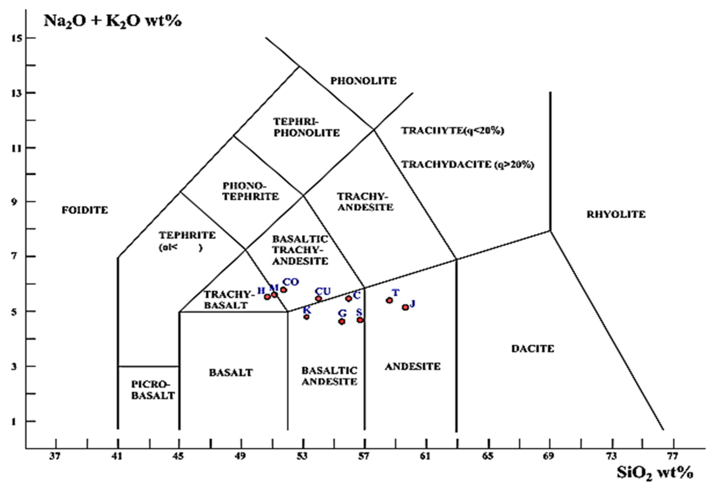
33]. In this research work, the Total Alkali-Silica (TAS) diagram (
Figure 7) was used which consists in classifying according to their ratio between SiO
2 wt. % content and the sum of NaO
2 wt. % and KO
2 wt. %.
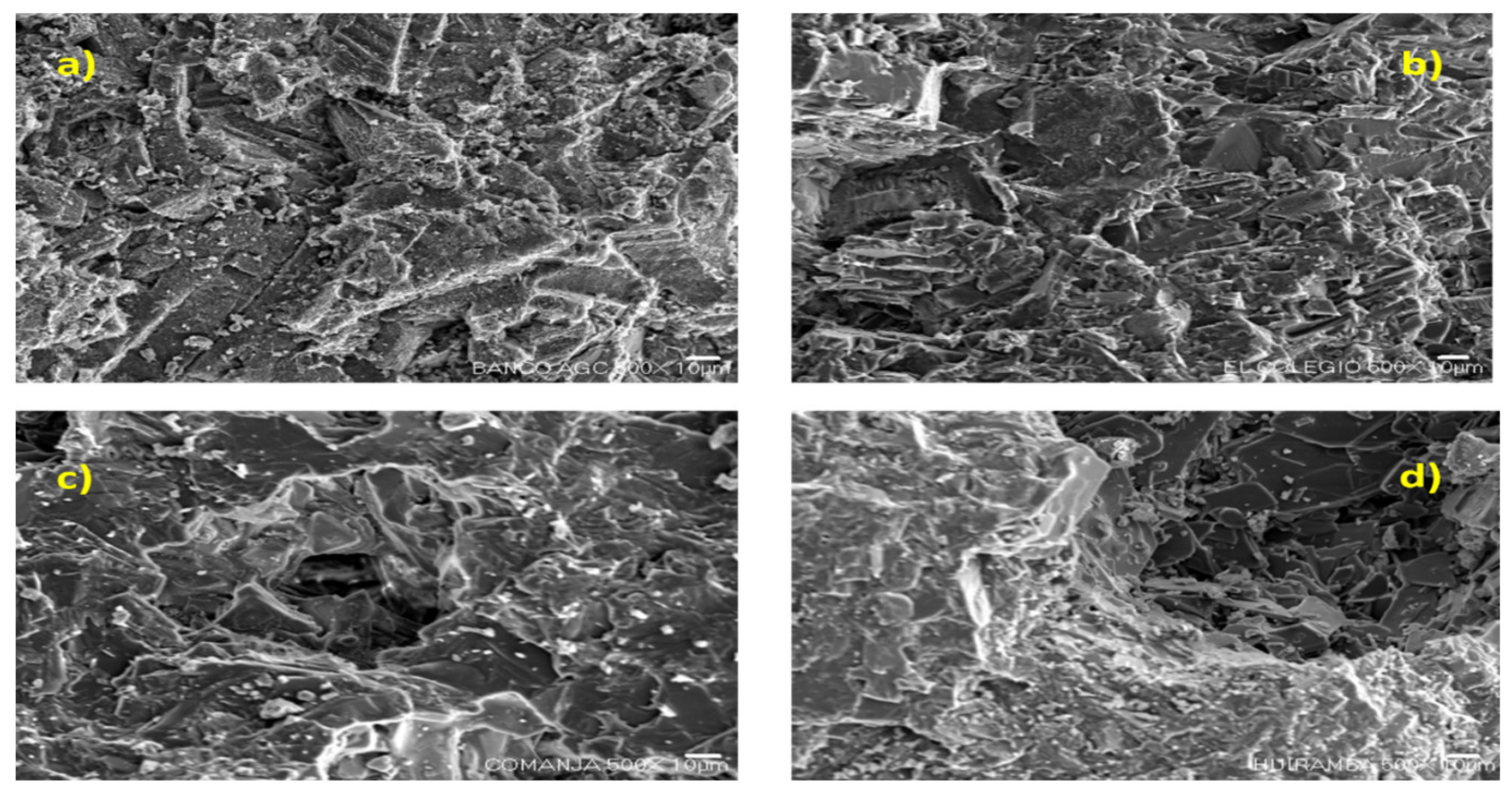
Figure 8 (a-d) shows SEM images of the AGC, El Colegio, Comanja and Huiramba quarries. The samples showed a surface composed of different shapes such as grains or slabs and the morphology observed in the four images is similar, the morphology between crushed and volcanic samples is very similar. In the four images a different change in relief is observed, presenting hollows in most cases, this could be interpreted as the porosity of the material.
The physical and mechanical properties were estimated as proposed in the experimental section, the values of density, uniaxial compressive strength and modulus of elasticity are showed in
Table 2. The samples with higher densities present higher uniaxial compressive strength (G and S), coming from volcanic material quarries. Samples G and S present the highest values of
UCS (110.10 MPa) and density (2567.00 kg/m3) respectively. Volcanic quarries H, C, K, M, CO, T, CU and J showed the lowest values in
UCS, density and primary waves (
Vp) compared to samples from crushed stone quarries, due to the fact that the uncrushed samples are weaker and more abrasive.
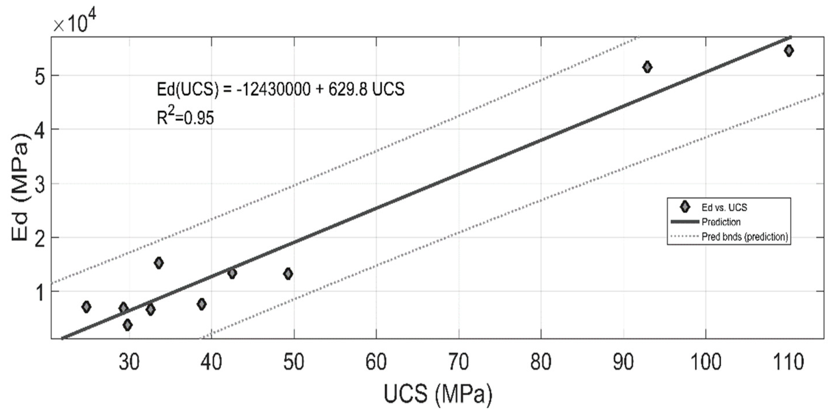
Figure 9 shows the linear correlation between UCS and Ed for the specimens analyzed in this study; the correlation coefficient was R2 = 0.95, which implies an excellent correlation [
37,
38]. Some previous research works have validated this correlation between uniaxial compressive strength and dynamic modulus of elasticity [
39,
40], the above data confirms the use of Equations 4 to 6 for an isotropic material.
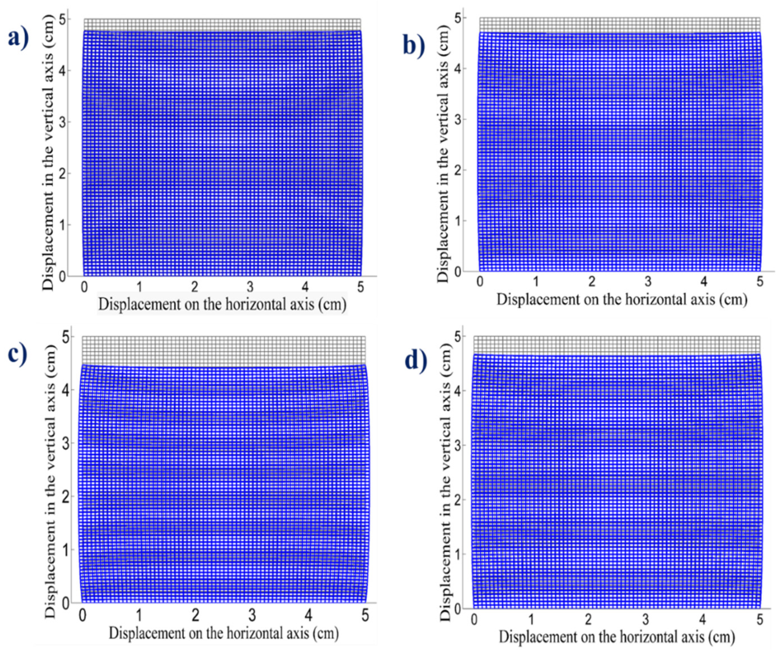
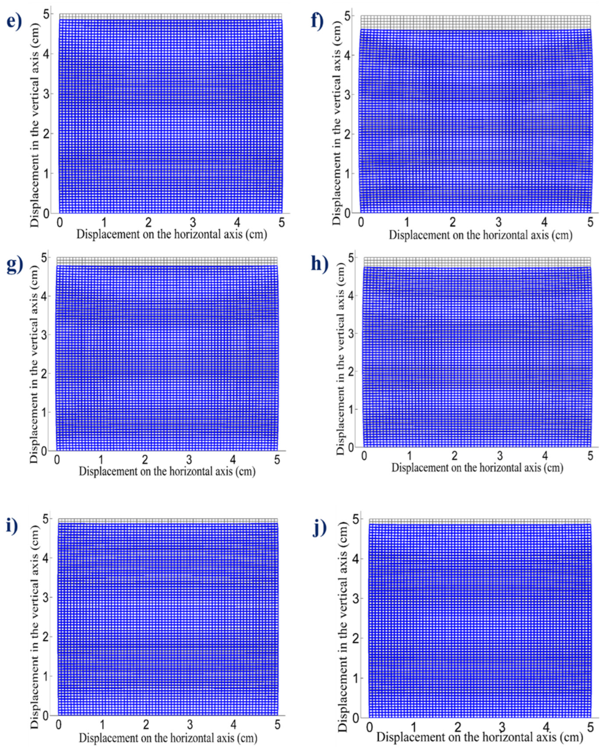
With the values of maximum applied load and dynamic modulus of elasticity, equations were discretized and coded in MATLAB using 5041 nodes per mesh to model the deformations and displacements. The application of the load at the top was considered, producing a value of uniaxial compressive strength, horizontal and vertical displacements. The values of the displacements obtained were amplified 15 times to appreciate the deformation in the images, which are shown in
Figure 10. The value of the dynamic modulus of elasticity obtained allowed classifying the rock and estimating its mechanical behavior.
Figure 10 a-j shows the 5cm x 5cm meshes that represent the profile of each cubic sample and the deformations are observed once the maximum load is applied, the above is obtained by the proposed FEM methodology, the effect of the maximum load on the sample is observed by superimposing the mesh without deformation (gray) and the deformed mesh of each sample (blue). Samples e, i and j in
Figure 10 presents the smallest deformations, while sample c presents the largest deformation when the load is applied. The deformations match with the values obtained from the physical and mechanical properties obtained with the characterizations (
Table 2).
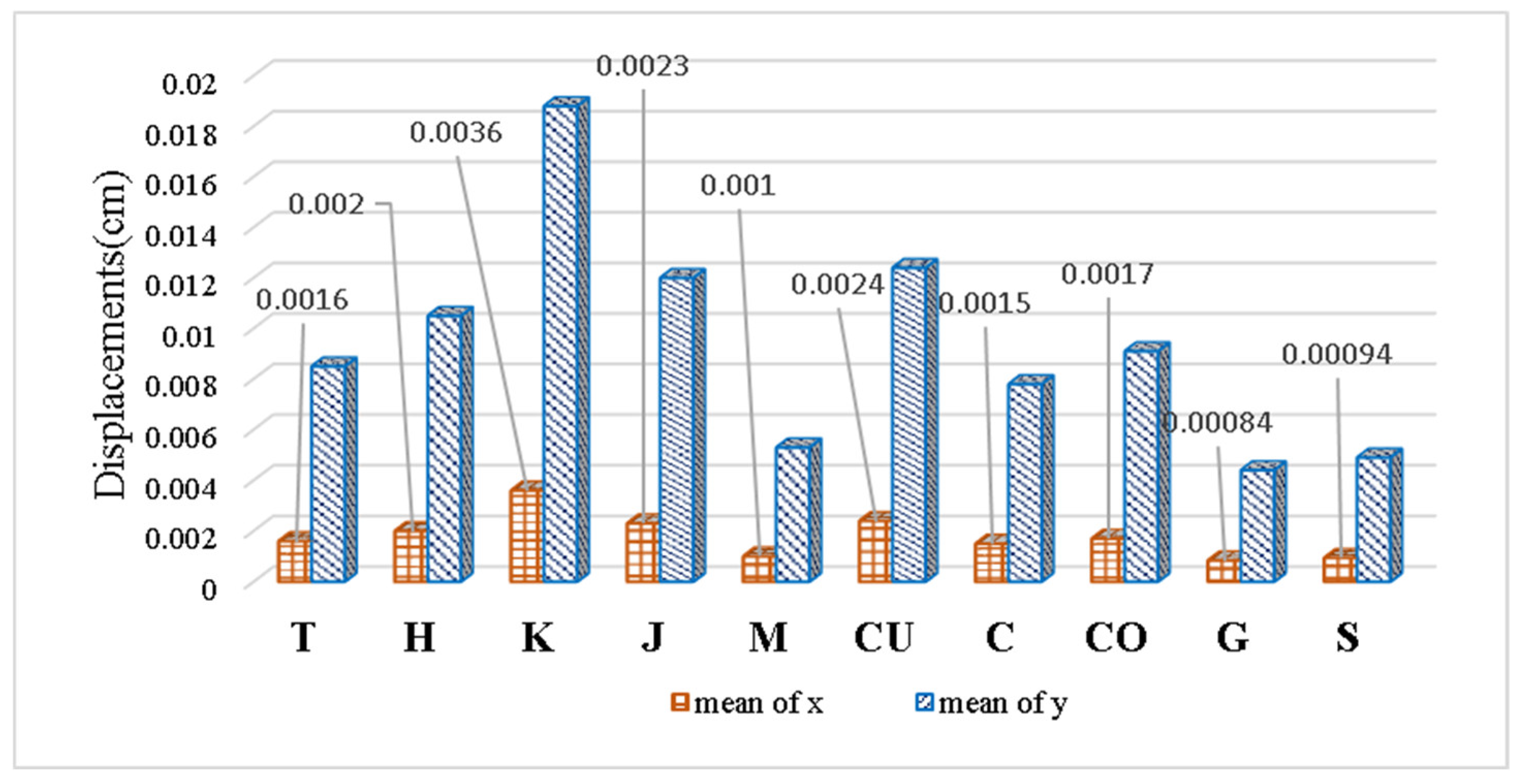
A comparison of the values of the mean displacements (x ̅ and y ̅) of each stone quarry is observed in
Figure 11. The values in shear stress displacement obtained are equal to less than 0.02 cm similar to those obtained by Vasconcelos and Lourenço 2009 [
41] and Pinho et al. 2021 [
42].
The results obtained are especially important because these quarries provide all the raw materials for the construction of civil infrastructure. The raw materials (volcanic and crushed) were analyzed, the results showed that the samples of crushed materials present better mechanical and physical properties, such as density and uniaxial compressive strength. In addition, the modulus of elasticity is higher compared to the volcanic samples.
Tests performed on different quarries, such as X-ray fluorescence (
Figure 6) indicate that the samples come from similar flows, the elements and chemical composition are similar, the SiO
2 values are between 50 and 60% for all quarries.
5. Conclusions
Different samples of stone quarry used for construction near the capital of Morelia, Michoacán, were analyzed. Physical and mechanical tests were performed and the values of density, modulus of elasticity and uniaxial compressive strength were compared. Results from model showed a clear difference between the crushed and volcanic quarry samples (crushed samples Ed 53035.1 MPa on average compared to volcanic samples Ed 9284.31 MPa on average). The samples from the crushed quarries showed lower average deformations and displacements (0.004 cm for the crushed samples and 0.018 cm for the volcanic samples). The sample with the best properties for construction activity corresponds to the El Colegio quarry.
The mathematical model proposed in this work can be applied to comprehend the deformations of the stones used in other regions and to determine the stone quarries with the best properties for construction use. The application of this methodology could aid decision makers by identifying the unexploited quarries that comply the construction requirements and so stopping the overexploitation of actual working quarries.
Author Contributions
Conceptualization, E. Alonso-Guzman; Investigation, H. Chavez-García; Visualization, W. Martinez-Molina and M. Arreola-Sanchez; Writing – original draft, M. Navarrete-Seras, J. Borrego-Perez and A. Cervantes-Servin; Writing – review & editing, J. Borrego-Perez and A. Cervantes-Servin. All authors have read and agreed to the published version of the manuscript.
Funding
The authors would like to acknowledge sponsorship from CIC Projects at the Universidad Michoacana de San Nicolas de Hidalgo, UMSNH; Secretaría de Educación Pública, SEP, Programa Prodep; Consejo Nacional de Ciencia y Tecnología, the CONAHCYT with the Border Science Group Project CF-2023-G-985, with the Pronace 321260; with the IXM-2313, with 315660 and 315680 Proposals and Programa Estancias Posdoctorales por México (J. A. Borrego Pérez CVU:460429); and Programa de Becas de Movilidad Académica entre Instituciones Asociadas a la Asociación Universitaria Iberoamericana de Posgrado ; the ICTI, Institute of Science and Technology of the State of Michoacán with ICTI,Project ICTI-PICIR23-0142 , and the Ing Luis Silva Ruelas Laboratory of the Faculty of Civil Engineering, UMSNH.
Informed Consent Statement
Not applicable.
Data Availability Statement
Data are contained within the article.
Conflicts of Interest
The authors declare no conflict of interest.
References
- W. Yao and K. Xia, “Dynamic notched semi-circle bend (NSCB) method for measuring fracture properties of rocks: Fundamentals and applications,” J. Rock Mech. Geotech. Eng. 2019. [CrossRef]
- F. I. Shalabi, E. J. Cording, and O. H. Al-Hattamleh, “Estimation of rock engineering properties using hardness tests,” Eng. Geol., vol. 90, no. 3, pp. 138–147, 2007,. [CrossRef]
- Ocak, “Estimating the modulus of elasticity of the rock material from compressive strength and unit weight,” J. South. African Inst. Min. Metall., vol. 108, no. 10, pp. 621–626, 2008.
- A. Al-Harthi, R. M. Al-Amri, and W. M. Shehata, “The porosity and engineering properties of vesicular basalt in Saudi Arabia,” Eng. Geol., vol. 54, no. 3, pp. 313–320, 1999. [CrossRef]
- S. Aboutaleb, M. Behnia, R. Bagherpour, and B. Bluekian, “Using non-destructive tests for estimating uniaxial compressive strength and static Young’s modulus of carbonate rocks via some modeling techniques,” Bull. Eng. Geol. Environ., vol. 77, no. 4, pp. 1717–1728, Nov. 2018. [CrossRef]
- E. Aladejare, V. O. Akeju, and Y. Wang, “Data-driven characterization of the correlation between uniaxial compressive strength and Youngs’ modulus of rock without regression models,” Transp. Geotech., vol. 32, p. 100680, Jan. 2022. [CrossRef]
- Z. Fang, J. Qajar, K. Safari, S. Hosseini, M. Khajehzadeh, and M. L. Nehdi, “Application of Non-Destructive Test Results to Estimate Rock Mechanical Characteristics—A Case Study,” Minerals, vol. 13, no. 4, p. 472, Mar. 2023. [CrossRef]
- Haghnejad, K. Ahangari, and A. Noorzad, “Investigation on Various Relations Between Uniaxial Compressive Strength, Elasticity and Deformation Modulus of Asmari Formation in Iran,” Arab J Sci Eng, vol. 39, pp. 2677–2682, 2014. [CrossRef]
- Pola, G. B. Crosta, N. Fusi, and R. Castellanza, “General characterization of the mechanical behaviour of different volcanic rocks with respect to alteration,” Eng. Geol., vol. 169, pp. 1–13, 2014. [CrossRef]
- E. Komurlu, F. Cihangir, A. Kesimal, and S. Demir, “Effect of Adhesive Type on the Measurement of Modulus of Elasticity Using Electrical Resistance Strain Gauges,” Arab. J. Sci. Eng., vol. 41, no. 2, pp. 433–441, Feb. 2016. [CrossRef]
- Azimian and R. Ajalloeian, “Empirical correlation of physical and mechanical properties of marly rocks with P wave velocity,” Arab. J. Geosci., vol. 8, no. 4, pp. 2069–2079, Apr. 2015. [CrossRef]
- S. Shen, Y. Gao, and L. Jia, “A Comparison of the Relationship between Dynamic and Static Rock Mechanical Parameters,” Appl. Sci., vol. 14, no. 11, p. 4487, May 2024. [CrossRef]
- S. M. Davarpanah, P. Ván, and B. Vásárhelyi, “Investigation of the relationship between dynamic and static deformation moduli of rocks,” Geomech. Geophys. Geo-Energy Geo-Resources, vol. 6, no. 1, p. 29, Mar. 2020. [CrossRef]
- Indraratna, N. T. Ngo, C. Rujikiatkamjorn, and S. W. Sloan, “Coupled discrete element–finite difference method for analysing the load-deformation behaviour of a single stone column in soft soil,” Comput. Geotech., vol. 63, pp. 267–278, Jan. 2015. [CrossRef]
- S. Abe, “Comparison of discrete element simulations to theoretical predictions of the elastic moduli of damaged rocks,” Int. J. Rock Mech. Min. Sci., vol. 88, pp. 265–272, 2016. [CrossRef]
- F. Chalupa, J. Vilhelm, M. Petruzálek, and Z. Bukovská, “Application of T-matrix model for static moduli approximation from dynamic moduli determined by sonic well logging,” Int. J. Rock Mech. Min. Sci., vol. 112, pp. 81–289, 2018, [Online]. Available:. [CrossRef]
- Shirole, G. Walton, L. Ostrovsky, H. Masoumi, and A. Hedayat, “Non-linear ultrasonic monitoring of damage progression in disparate rocks,” Int. J. Rock Mech. Min. Sci., vol. 111, pp. 33–44, 2018. [CrossRef]
- M. Coli, A. L. Ciuffreda, and T. Donigaglia, “Technical Analysis of the Masonry of the Bargello’ Palace, Florence (Italy),” Appl. Sci., vol. 12, no. 5, p. 2615, Mar. 2022. [CrossRef]
- P. Zoccali et al., “Analysis of natural stone block pavements in urban shared areas,” Case Stud. Constr. Mater., vol. 8, pp. 498–506, Jun. 2018. [CrossRef]
- X. F. Li, H. B. Li, L. W. Liu, Y. Q. Liu, M. H. Ju, and J. Zhao, “Investigating the crack initiation and propagation mechanism in brittle rocks using grain-based finite-discrete element method,” Int. J. Rock Mech. Min. Sci., vol. 127, p. 104219, Mar. 2020. [CrossRef]
- L.-F. Wang and X.-P. Zhou, “A field-enriched finite element method for simulating the failure process of rocks with different defects,” Comput. Struct., vol. 250, p. 106539, Jul. 2021. [CrossRef]
- X. Zhou, Z. Jia, and L. Wang, “A field-enriched finite element method for brittle fracture in rocks subjected to mixed mode loading,” Eng. Anal. Bound. Elem., vol. 129, pp. 105–124, Aug. 2021. [CrossRef]
- S. D18.12, Standard Test Method for Laboratory Method for Density, Relative Density (Specific Gravity), and Absorption of Coarse Aggregate ASTM C127-04. American Society for Testing Materials (ASTM), 2015.
- S. D18.12, Standard Test Method for Unconfined Compressive Strength of Intact Rock Core Specimens (ASTM D2938-95(2002)). American Society for Testing Materials (ASTM), 2002.
- L. Navarro, W. L. Navarro, W. Martínez, and A. Espinoza, ANÁLISIS DE MATERIALES, Manual de Análisis de Materiales, Resistencia de Materiales. 2011.
- Chawre, “Correlations between ultrasonic pulse wave velocities and rock properties of quartz-mica schist,” J. Rock Mech. Geotech. Eng., vol. 10, no. 3, pp. 594–602, Jun. 2018,. [CrossRef]
- S. D18.12, Standard Test Method for Laboratory Determination of Pulse Velocities and Ultrasonic Elastic Constants of Rock (ASTM D2845-08). American Society for Testing Materials (ASTM), 2008.
- L.-I. González-De-Vallejo and M. Ferrer, Geological Engineering. CRC Press/Balkema, 2011.
- M. Hakala, H. Kuula, and J. A. Hudson, “Estimating the transversely isotropic elastic intact rock properties for in situ stress measurement data reduction: A case study of the Olkiluoto mica gneiss, Finland,” Int. J. Rock Mech. Min. Sci., vol. 44, no. 1, pp. 14–46, Jan. 2007. [CrossRef]
- Sun et al., “Influences of Permian igneous rock on seismic imaging of underlying strata in the Hanilcatam area, Tarim Basin, China,” J. Nat. Gas Geosci., vol. 4, no. 1, pp. 71–77, Feb. 2019. [CrossRef]
- H. Wang, J. Jia, X. Li, X. Xian, and G. Hu, “Cranny density parameters and porosity measured by elastic wave method in quasi-isotropic cranny rock masses,” J. Cent. South Univ. Technol., vol. 13, no. 5, pp. 598–602, Oct. 2006. [CrossRef]
- P. I. Kattan, “The Plane Truss Element,” in MATLAB Guide to Finite Elements: An Interactive Approach, Berlin, Heidelberg: Springer Berlin Heidelberg, 2008, pp. 61–89. [CrossRef]
- H. R. Rollinson, Using Geochemical Data. Routledge, 2014. [CrossRef]
- M. C. Geisenblosen, P. Oyhantçabal, and M. Pistón, “Determination of major elements in igneous rocks using microwave plasma atomic emission spectrometry (MP-AES),” MethodsX, vol. 9, p. 101793, 2022. [CrossRef]
- R. W. Le Maitre, “A proposal by the IUGS Subcommission on the Systematics of Igneous Rocks for a chemical classification of volcanic rocks based on the total alkali silica (TAS) diagram,” Aust. J. Earth Sci., vol. 31, no. 2, pp. 243–255, Jun. 1984. [CrossRef]
- M. J. L. BAS, R. W. L. MAITRE, A. STRECKEISEN, and B. ZANETTIN, “A Chemical Classification of Volcanic Rocks Based on the Total Alkali-Silica Diagram,” J. Petrol., vol. 27, no. 3, pp. 745–750, Jun. 1986. [CrossRef]
- Figeroa Montaño, H. U. Ramírez Sánchez, and J. Alcalá Gutiérrez, Introducción a la metodología experimental., Primera. EARSON EDUCACIÓN., 2014.
- Silva, J. de Brito, and P. L. Gaspar, Methodologies for Service Life Prediction of Buildings With a Focus on Façade Claddings. Springer, Cham, 2016. [CrossRef]
- J. Majstorović, M. Gligorić, S. Lutovac, M. Negovanović, and L. Crnogorac, “Correlation of uniaxial compressive strength with the dynamic elastic modulus, P - wave velocity and S - wave velocity of different rock types,” Podzemn. Rad., no. 34, pp. 11–25, 2019. [CrossRef]
- R. Najibi, M. Ghafoori, G. R. Lashkaripour, and M. R. Asef, “Empirical relations between strength and static and dynamic elastic properties of Asmari and Sarvak limestones, two main oil reservoirs in Iran,” J. Pet. Sci. Eng., vol. 126, pp. 78–82, Feb. 2015. [CrossRef]
- G. Vasconcelos and P. B. Lourenço, “Experimental characterization of stone masonry in shear and compression,” Constr. Build. Mater., vol. 23, no. 11, pp. 3337–3345, Nov. 2009. [CrossRef]
- F. F. S. Pinho, R. J. G. Serra, A. F. L. Saraiva, and V. J. G. Lúcio, “Performance of single and double flat jacks in stone masonry lab tests,” J. Build. Eng., vol. 42, p. 102465, Oct. 2021. [CrossRef]
Figure 1.
Location of stone quarries in the surroundings of Morelia, Michoacán, Mexico (Google Earth, 2023).
Figure 1.
Location of stone quarries in the surroundings of Morelia, Michoacán, Mexico (Google Earth, 2023).
Figure 2.
El Colegio stone quarry, Morelia, Michoacán, Mexico.
Figure 2.
El Colegio stone quarry, Morelia, Michoacán, Mexico.
Figure 3.
Sample rock cube 5 x 5 x 5 cm.
Figure 3.
Sample rock cube 5 x 5 x 5 cm.
Figure 4.
a) Forney universal testing machine and b) Specimen.
Figure 4.
a) Forney universal testing machine and b) Specimen.
Figure 5.
Bilinear element in physical coordinate.
Figure 5.
Bilinear element in physical coordinate.
Figure 6.
X-ray fluorescence.
Figure 6.
X-ray fluorescence.
Figure 7.
TAS diagram (Total Alkali-Silica) [
35,
36].
Figure 7.
TAS diagram (Total Alkali-Silica) [
35,
36].
Figure 8.
SEM images of (a) AGC, (b) El Colegio, (c) Comanja, and (d) Huiramba quarries (500X 10µm).
Figure 8.
SEM images of (a) AGC, (b) El Colegio, (c) Comanja, and (d) Huiramba quarries (500X 10µm).
Figure 9.
Correlation between UCS and Ed.
Figure 9.
Correlation between UCS and Ed.
Figure 10.
Deformation of stone samples from different material quarries: (a) ) Tigre (T) is andesite, (b) Huiramba (H) is trachybasalt, (c) Mascutan (K) is basaltic andesite, (d) Joyitas (J) is andesite, (e) Melon (M) is trachybasalt, (f) Cuenembo (CU) is basaltic trachyandesite, g) Cerritos (C) is basaltic andesite, h) Comanja (CO) is basaltic trachyandesite, i) Colegio (S) is basaltic andesite and j) AGC (G) is basaltic andesite.
Figure 11.
Displacements x ̅ and y ̅.
Figure 11.
Displacements x ̅ and y ̅.
Table 1.
Name of the stones, symbology and type of stone analyzed.
Table 1.
Name of the stones, symbology and type of stone analyzed.
| Quarry number |
Quarry name |
Symbology |
Stone name (Total Alkali–Silica) |
| 1 |
AGC o Mesón Nuevo |
G |
Basaltic andesite |
| 2 |
El Colegio |
S |
Basaltic andesite |
| 3 |
Huiramba |
H |
Trachybasalt |
| 4 |
Cerritos |
C |
Basaltic andesite |
| 5 |
Mascutan |
K |
Basaltic andesite |
| 6 |
El Melon |
M |
Trachybasalt |
| 7 |
Comanja |
CO |
Basaltic trachyandesite |
| 8 |
El Tigre |
T |
Andesite |
| 9 |
Cuenembo |
CU |
Basaltic trachyandesite |
| 10 |
Joyitas |
J |
Andesite |
Table 2.
Density, uniaxial compressive strength, primary wave velocity and dynamic modulus of elasticity (of UPV).
Table 2.
Density, uniaxial compressive strength, primary wave velocity and dynamic modulus of elasticity (of UPV).
| Samples |
|
|
Vp (m/s) |
(MPa) |
| T |
1356.00 |
24.80 |
1458.44 |
7195.40 |
| H |
1597.00 |
29.30 |
1397.56 |
6902.80 |
| K |
1427.00 |
29.80 |
888.44 |
3817.50 |
| J |
1474.00 |
32.60 |
1130.67 |
6679.40 |
| M |
1704.00 |
33.60 |
1932.22 |
15283.50 |
| CU |
1680.00 |
38.80 |
1091.33 |
7692.10 |
| C |
1439.00 |
42.50 |
2005.78 |
13434.50 |
| CO |
1638.00 |
49.30 |
1782.22 |
13269.30 |
| G |
2567.00 |
92.90 |
2968.89 |
51494.80 |
| S |
2472.00 |
110.10 |
3117.11 |
54575.30 |
|
Disclaimer/Publisher’s Note: The statements, opinions and data contained in all publications are solely those of the individual author(s) and contributor(s) and not of MDPI and/or the editor(s). MDPI and/or the editor(s) disclaim responsibility for any injury to people or property resulting from any ideas, methods, instructions or products referred to in the content. |
© 2024 by the authors. Licensee MDPI, Basel, Switzerland. This article is an open access article distributed under the terms and conditions of the Creative Commons Attribution (CC BY) license (http://creativecommons.org/licenses/by/4.0/).
