1. Introduction
Energy harvesting is becoming and emerging topic specially in the recent decades due to Global energy challenges and sustainability objectives. Energy harvesting is called on any methodology that capture energy from a currently operation system and convert it into electricity to provide energy to operate elements in the system such as sensors. Energy can be harvested from vibrations, light, radio frequency, magnetic and thermoelectric [
1].
Energy harvesting from spinning objects became of a main concern as it can be applied in various applications such as automotive, wind turbines, aerospace, etc. The centrifugal forces generated from the rotation itself can be invested to self-fit the natural frequency of harvester with the driving frequency [
1]. Induction system or piezoelectric material are being used in the harvester design. For induction, different structures are developed for the magnets and coils to have optimum energy harvested out of the system. While for piezoelectric materials, both piezoelectric structure and the strain methodology can be varied to optimize the harvested energy. The strain methodology for piezoelectric material varies from compress the material itself or vibrating a piezoelectric beam to generate electricity from its strain. Gu & Livermore [
1] monitored the change in the natural frequency of a cantilever beam installed on a spinning fan across the rising rotating/spinning driving frequency. They concluded a curve fitting between the mentioned two frequencies which can build-on to have a passive energy harvesting mechanism.
Lee et al. [
2] proposed a harvester that can extract electrical energy out of spinning objects, by utilizing a structure containing a metallic movable arm and magnet. This arm has a tip mass which will be pointed to this fixed magnet on the rim due to the magnetic attraction. When the rotation speed exceeds a certain speed, the arm will move suddenly with high-speed generating high energy. This harvester can be used on any spinning object specially sensors that are installed on the spinning object to measure anything, no need for outside power source or brushes to transfer this power, even it supports the sustainability idea.
Roundy and Tola [
3] proposed a harvester of a freely movable ball in a slot where a piezoelectric beam was installed in the way of this ball. So, when the car wheel completes a one rotation, the ball will change its position from one side in the slot to the other due to gravity and on its way hitting the piezoelectric beam and generate electric pulse. Wang et al. [
10], used the induction electricity generation to design an energy harvester from rotating wheels using permanent magnet as a mass with two springs and two coils which was designed to be installed to a car wheel rim. Due to the rotation with the rim, the proof mass will move due to gravity and form induction with a fixed coil like the generator idea. However, this developed system is only applicable for low speeds only to allow the gravity to play its role.
Windmills has another way to harvest energy not only from winds but also from the blade rotation using an induction mechanism to harvest energy [
5]. The harvested energy is used to supply power to a crack sensor installed on the blades itself. The proposed harvester consists of a tube with a permanent magnet free to move inside due to gravity and a fixed coil in the middle. Due to rotation, the gravity will affect the movable magnet and make it move across the fixed coil generating electricity. Different units from this harvester can be used in same windmill to maximize harvested energy. Yi-Chung Shu et al [
6] developed a theoretical framework with an experimental review for investigating a spinning harvester that uses piezoelectric energy to the standard interface circuit for AC-DC conversion. The harvester composed of a piezoelectric cantilever beam fixed on a stationary base with a magnet attached to its tip. The Energy was harvested by vibrating the beam induced by rotary magnetic plucking under non-contact. A theoretical model was developed for magnetic coupling and rotary plucking as the nature of frequency up-conversion is realized by the Fourier analysis of following up driving force.
A spinning-type energy harvester has been designed and developed to harvest energy resulting from rotary motion system in Narolia et al [
7]. It depends on converting kinetic rotation energy into electrical energy through a piezoelectric material that deformed by magnetic force. The research proposed a d33 harvesting mode with radial direction piezo material. Two models had been developed of mathematical and finite element to estimate the harvested energy. Experimental work had been conducted to verify results. The harvester average output power was 14.48 nW generated in regards of a magnetic force of 0.3126 N and spinning speed of 2100 r/min.
In this research, a new energy harvesting mechanism from spinning objects using vibrations was proposed. The proposed mechanism aims to increase the efficiency of harvested energy through an active fitting methodology where the vibrating element is at resonance condition. This can be achieved by actively customizing the vibrating element beam length to manipulate its natural frequency according to the spinning frequency.
2. Materials and Methods
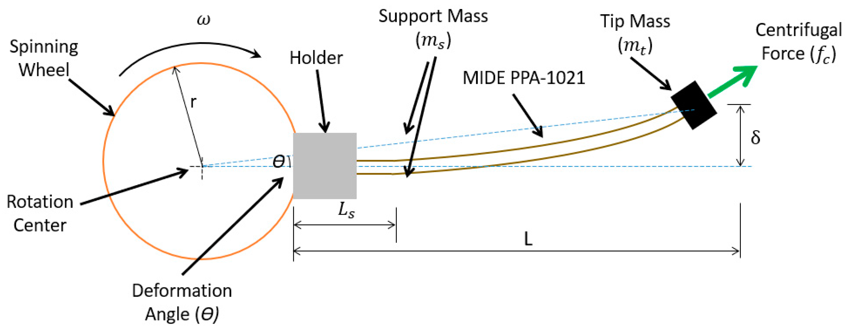
The proposed harvester is shown in
Figure 1. The design depends on investing the centrifugal force generated from the spinning to stiff the cantilever of the harvesting element and increase its natural frequency. Self-fitting for the natural frequency of the harvester to follow the current driving frequency instantly. This cantilever stiffness due to centrifugal force will tend to reach the optimum required fitting with the driving frequency at all speeds.
The new derived methodology was to amend the length of the cantilever/harvester manually/active. This amendment in the length of harvester will lead directly to a change in its natural frequency. By increasing the length harvester, its natural frequency will be decreased and vice versa. The support of cantilever is made movable to freely can change its length as shown in
Figure 1 and
Figure 2.
Table 1.
Detailed internal structure for MIDE PPA-1021.
Table 1.
Detailed internal structure for MIDE PPA-1021.
| Layer Material |
Thickness (mils) |
Thickness (mm) |
| FR4 |
3 |
0,08 |
| Copper |
1,4 |
0,03 |
| PZT 5H |
10,0 |
0,25 |
| Copper |
1,4 |
0,03 |
| FR4 |
14,0 |
0,36 |
| Total |
29,0 |
0,74 |
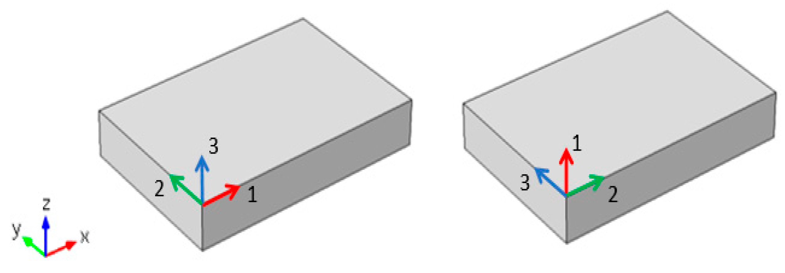
A model has been built using COMSOL Multiphysics Version 5.1 under finite element to simulate the proposed harvester and to test its results. The proposed harvester was modelled in details simulate its behavior, polarization on COMSOL Multiphysics software were defined in a certain crystal coordinate system that is defined by 3-axes 1, 2, and 3. and, material’s poling direction is considered to be the 3rd axis as shown in
Figure 3.
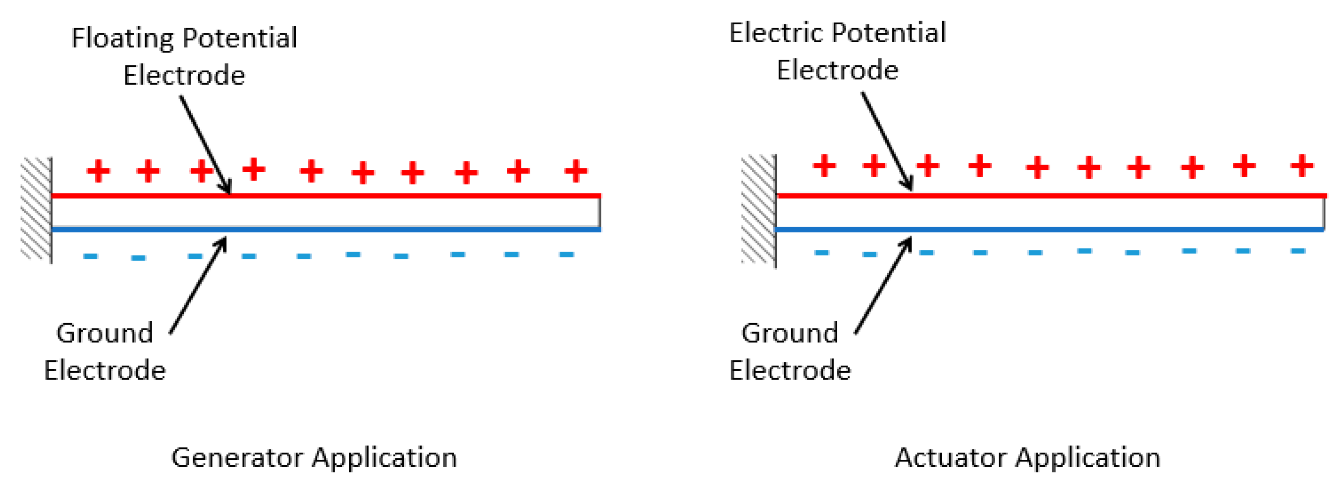
Electrodes in any piezoelectric material has a critical important rule in any piezoelectric material as when any piezoelectric material was subjected to a certain amount of mechanical strain, electrodes play the rule of collecting all the generated charges along the material. Electrodes assign from the application of the piezoelectric material, generator, or actuator,
Figure 4.
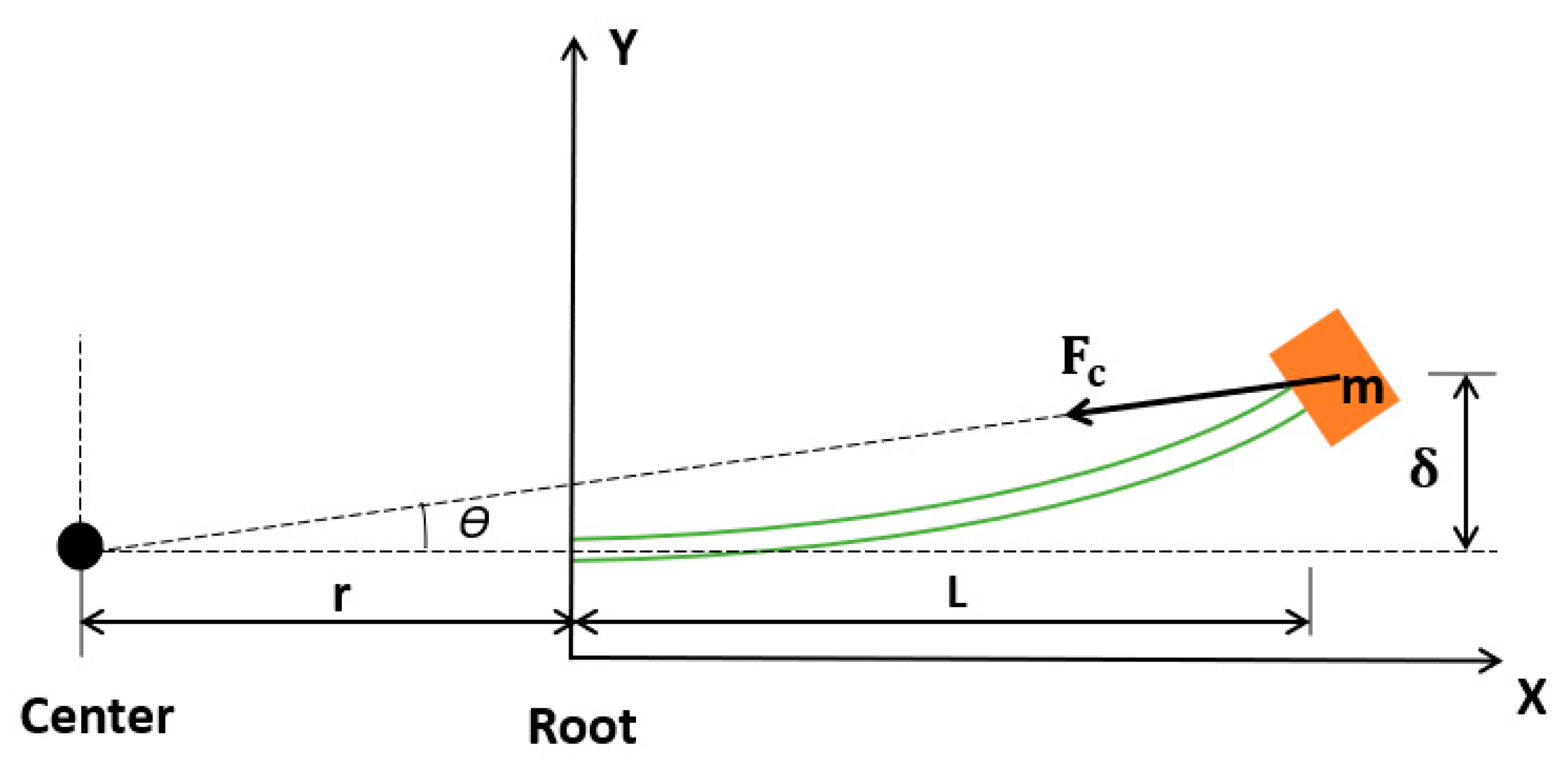
According to the proposed harvester design, system is subjected to different forces that controls its behavior such as centrifugal forces, and gravity effect on beam due to rotation,
Figure 5.
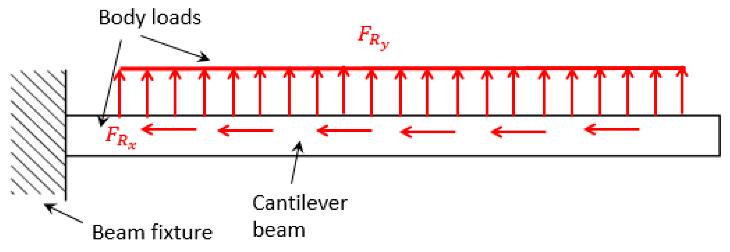
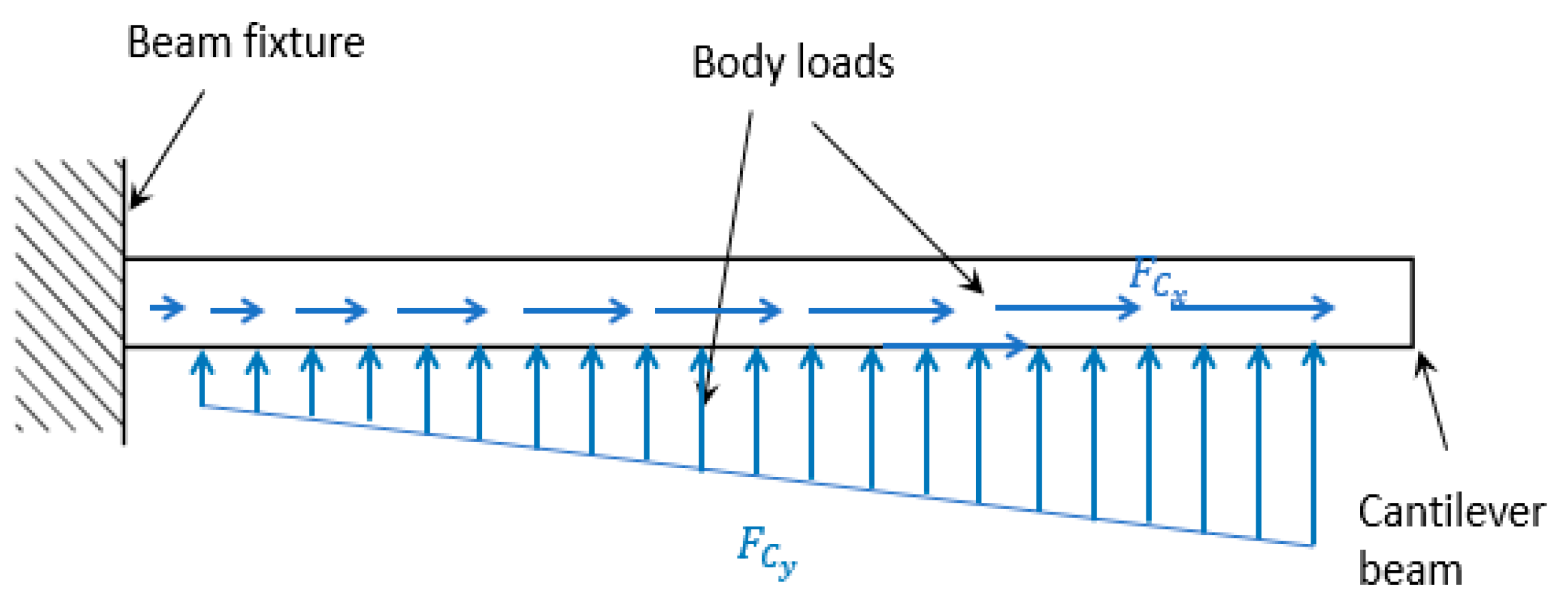
Away from actual rotation for beam on software, two body loads,
Figure 6, were added to beam to simulate the same gravity effect due to rotation, Eq. (1) and (2).
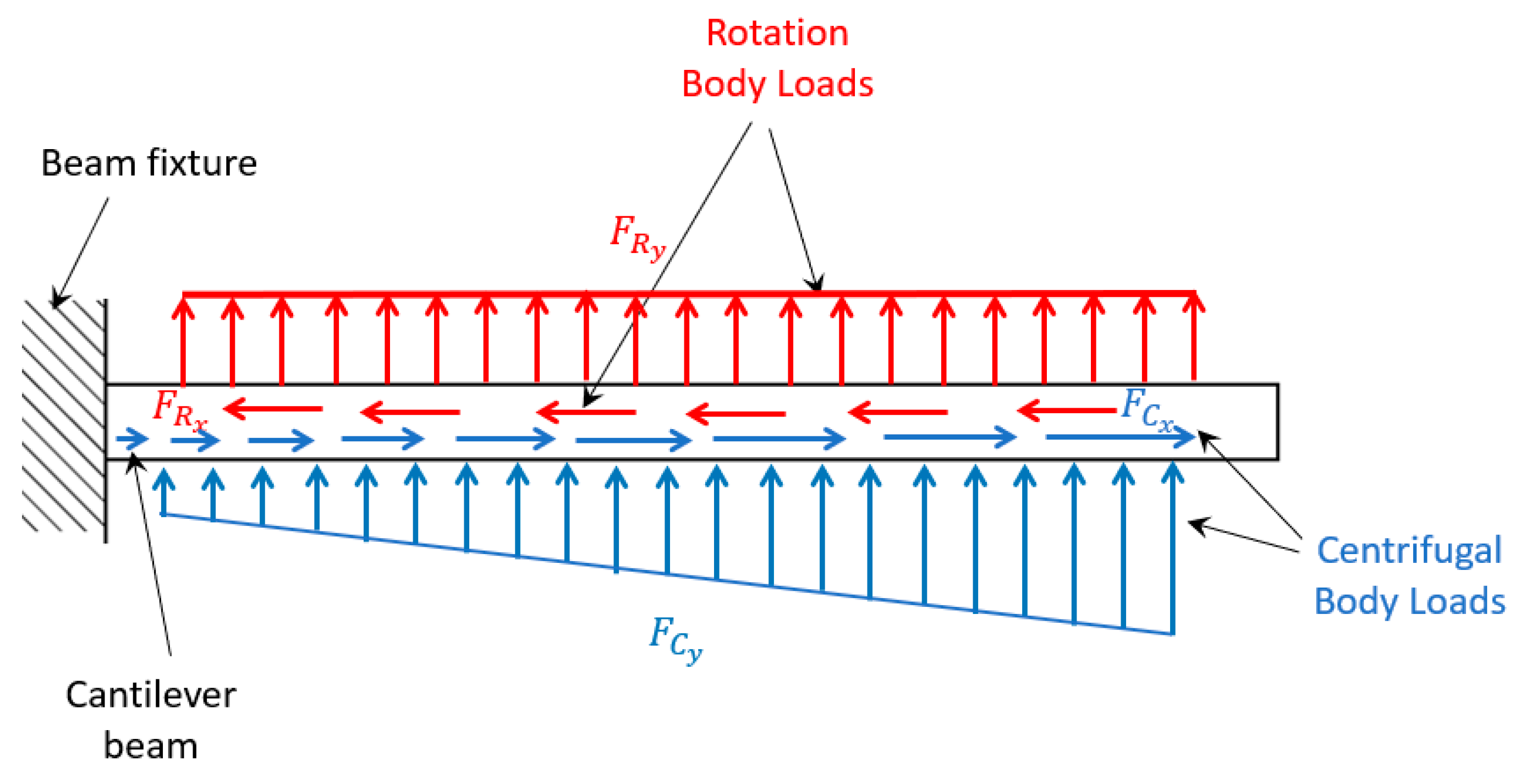
To simulate the effect of centrifugal forces on beam, two mechanical body loads were applied,
Figure 7, and expressed in Eq. (3) and (4).
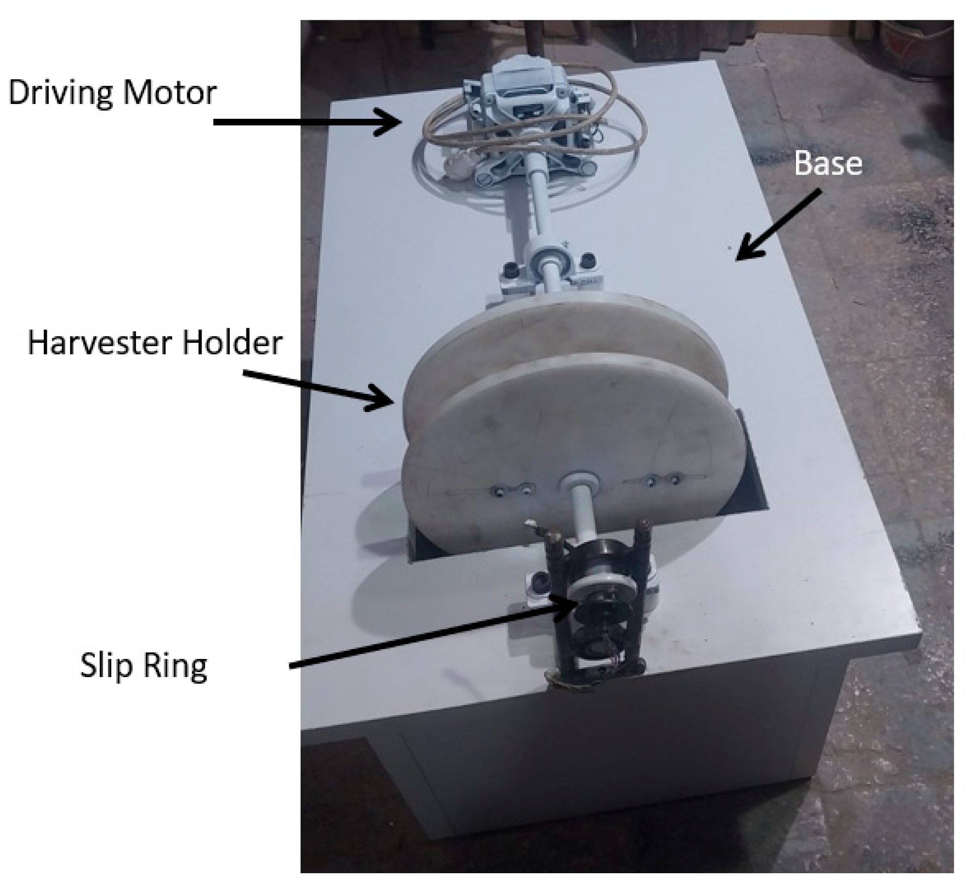
Experimental setup was held as shown in
Figure 8 consisting of an electric motor to drive the system, and slip ring to transfer the harvested electric voltage difference. The electric motor is controlled by a driver to test the system under different rotation speeds. The piezoelectric is installed into the harvester holder.
3. Numerical Model Benchmarking
To check the proposed numerical finite element model using COMSOL Multiphysics software V5.1, benchmarking steps had been conducted to previously published work [
1,
9,
10]. The proposed harvester is subjected to different parameters during spinning like gravity and centrifugal force due to the spinning at different speeds (0-200Hz). Each of these sides had to be modelled and verified individually.
An experimental and numerical model was proposed by Gu et al [
1] to study the generated centrifugal force effect from a spinning speed on natural frequency of the beam. The generated centrifugal force gives a pulling effect on the cantilever beam that gives more stiffness to it leading its natural frequency to increase. The studied model is shown in
Figure 9, experimental and numerical models were implemented under the properties shown in
Table 2. The study measured and plotted the changes in natural frequency of beam verses the driving rotational speed. The relation between the following, produced centrifugal forces (
fc), rotating radius (
r), beam length (
l) and driving frequency (
ωd) is expressed in Eq. (5).
A clear mathematical model was conducted by Park and Moon [
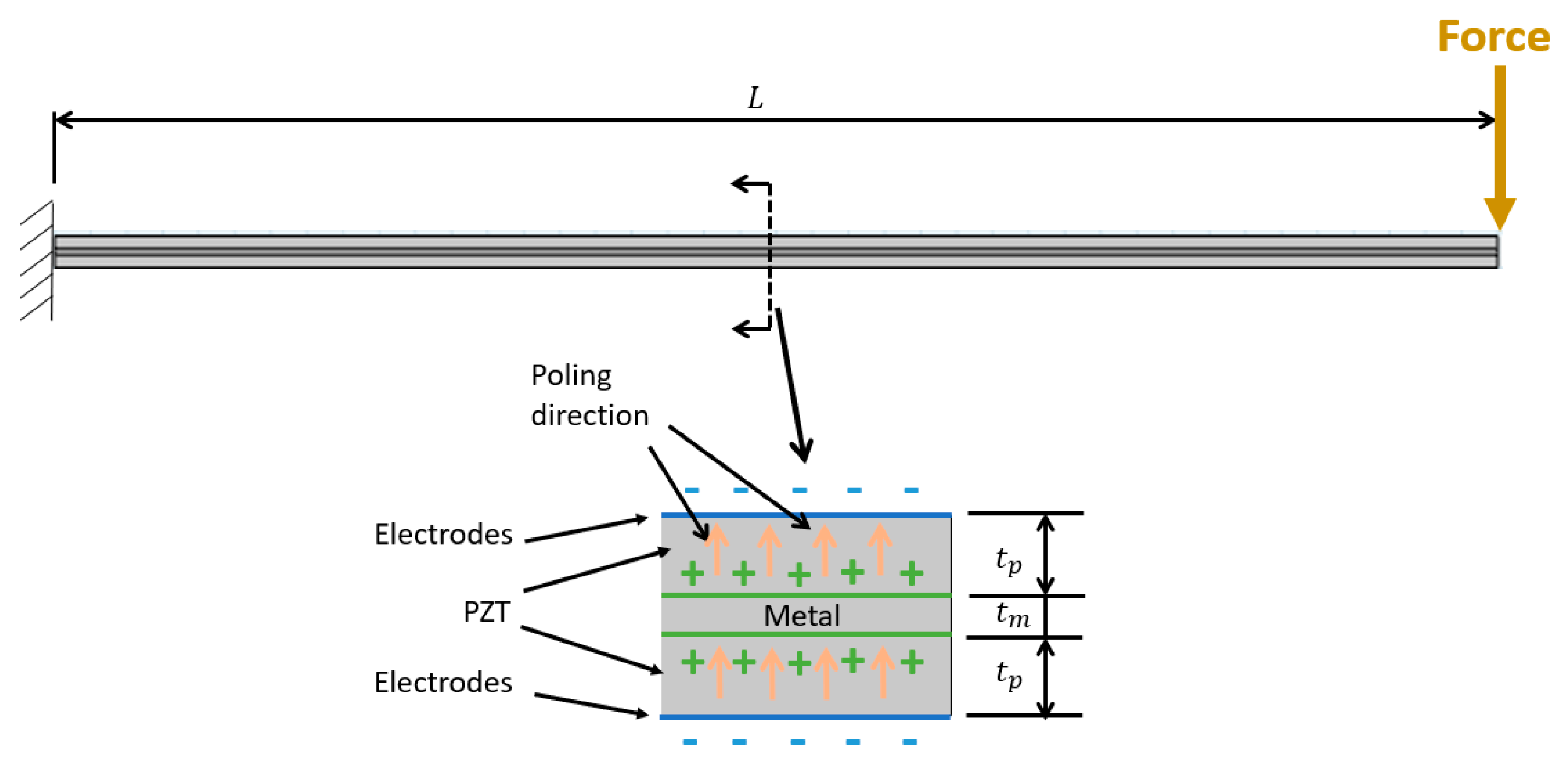
9] for different piezoelectric material compositions such as unimorph, bimorph, and triple-layer bender. Each of these cases was studied under applied a tip force N and voltage difference V. To benchmark the finite element model using COMSOL Multiphysics, the triple-layer bender case was chosen because of its simple construction to the used piezoelectric beam of multiple layer bender. The internal structure of beam is shown in
Figure 5 of length (
, piezoelectric material thickness (
, and metal thickness (
.
A mathematical model was conducted by Wang & Cross [
10] for a triple-layer bender composition of metallic beam surrounded as a sandwich by two piezoelectric material slices. This composition was affected by various loads such as an electric field on triple layer bender, an electric voltage and an external moment on triple layer bender, an electric voltage and an external tip force on triple layer bender, and an electric voltage and an external load on triple layer bender. The triple-layer bender subjected to an electric voltage and an external tip force was chosen to benchmark it with the COMSOL Multiphysics model because of its similarity to this work and to triple-layer structure developed by Park & Moon [
9]. The internal structure of the beam is shown in
Figure 10 with length (
, piezoelectric material length (
, and metal length (
. piezoelectric material thickness
, and metal thickness
.
Regarding to [
9] and [
10] studied mathematical model as Eq. (6) showed a general representing behavior relation for the triple-layer bender subjected by tip force (
P) and voltage difference (
V) along its electrodes. As long as the structure has one metallic layer surrounded by two piezoelectric layers so, the possible available electric connections are two.
The two proposed models for [
9] and [
10] were studied using different amounts of tip forces and voltage differences with parameters,
Table 3.
4. Research Numerical Model
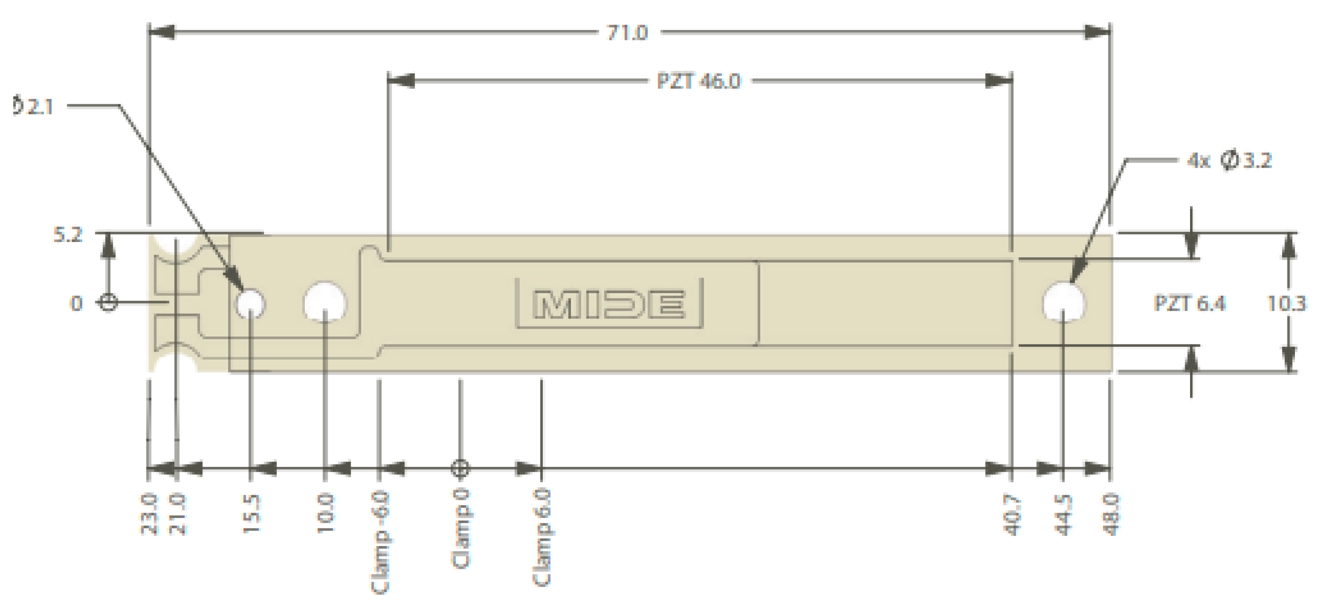
Based on the previous COMOSL Multiphysics benchmarking models, a numerical model had been conducted to simulate the harvester’s performance, the MIDE PPA-1021 piezoelectric beam was drawn on the software by its internal construction mentioned in the datasheet shown in
Figure 2. The model was not only conducted mechanically but also it was conducted electrically which gives the software the ability to estimate the electricity that we can get through the subjected beam deformation due to vibration. Each design parameter (centrifugal force, rotation frequency and piezoelectric material) was simulated individually to form the whole system, such as, the rotation was simulated as a body load that varies from 0 to 200 Hz with respect to the instant gravity effect to avoid the actual rotation for the system to be able to measure the tip deformation/vibration, simulation of the centrifugal force effect was conducted using a boundary load which amplitude related to the current rotation speed, electricity harvested was also simulated on COMSOL Multiphysics V5.1 by identifying the ground line and the floating potential side which helps the electrons to transfer and generate electricity in relation to the proper strain direction.
5. Results
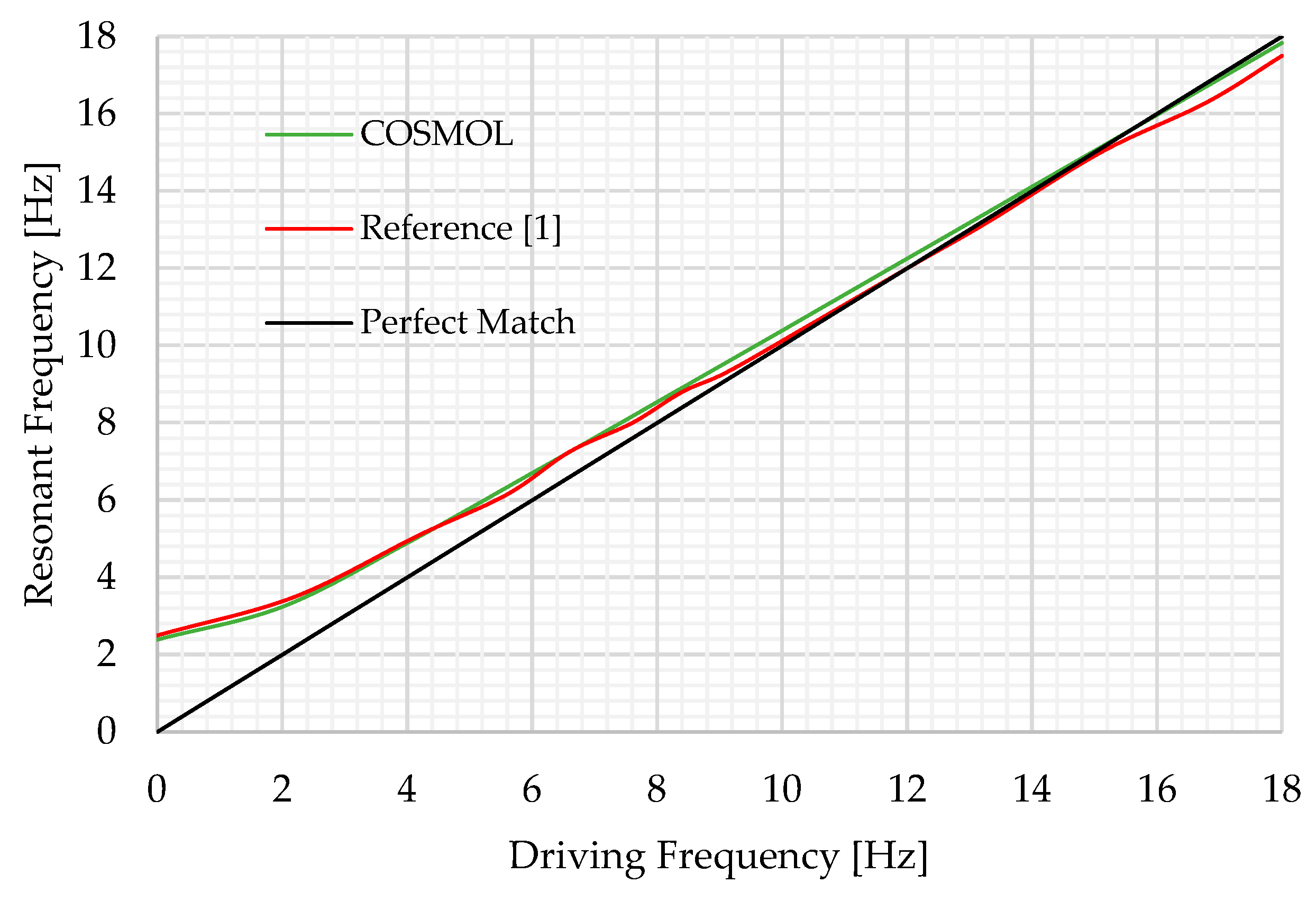
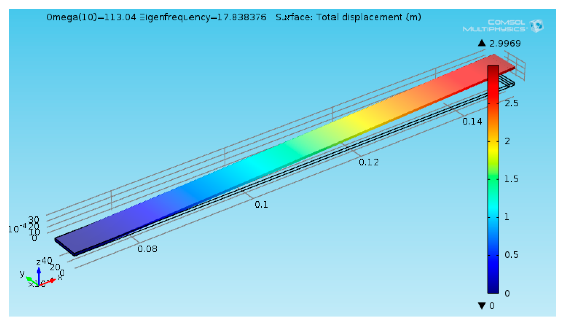
Figure 11 illustrates a plot of the natural frequency versus driving frequencies ranging (0 - 18) Hz with the perfect match optimum line. To benchmark the developed COMSOL Multiphysics V5.1, the same beam design was conducted on it as shown in
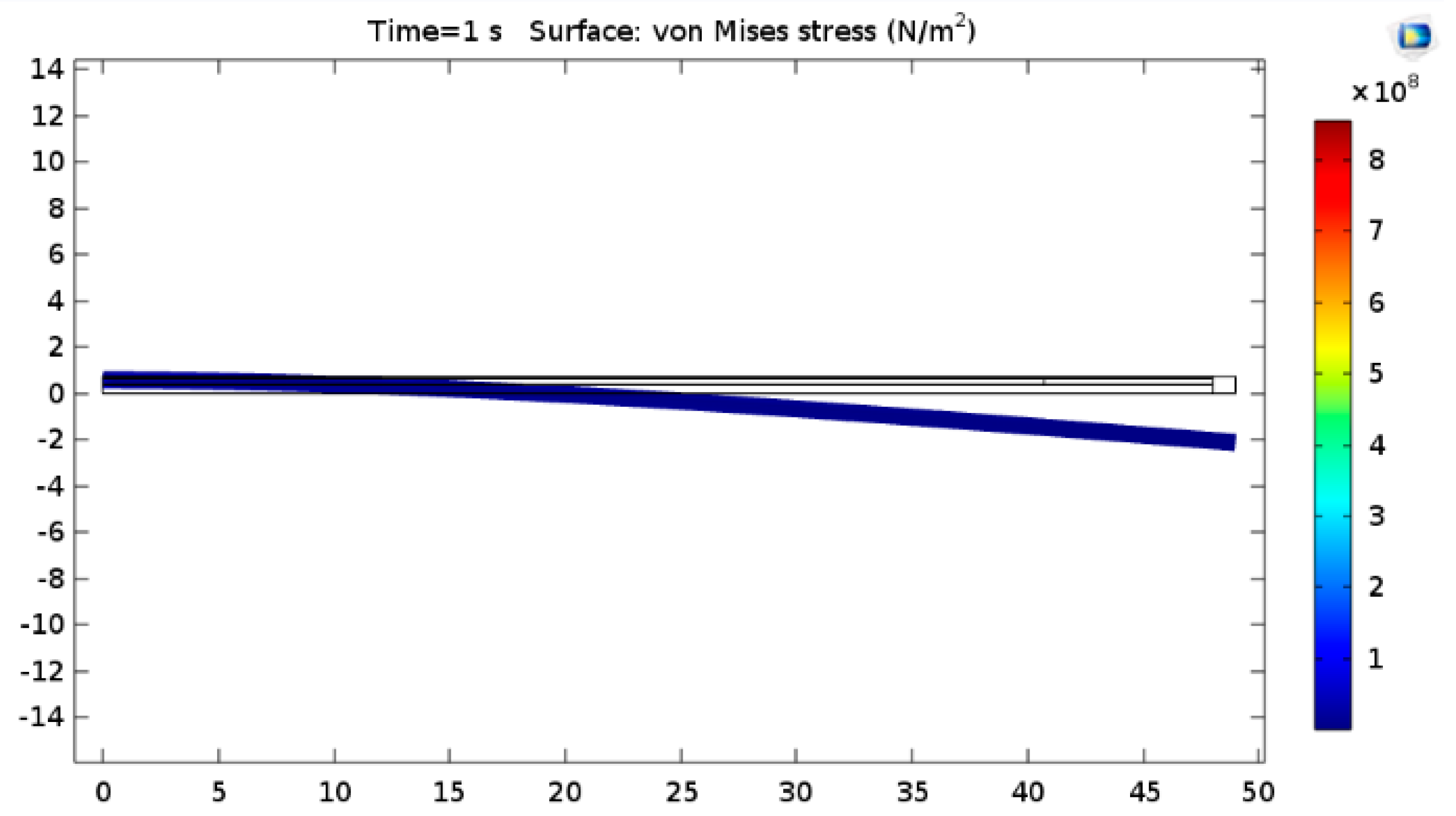
Figure 12 under same parameters and driving frequency ranges. The comparison between all three results were implemented on figure 11.
Results of the proposed numerical model benchmarking with [
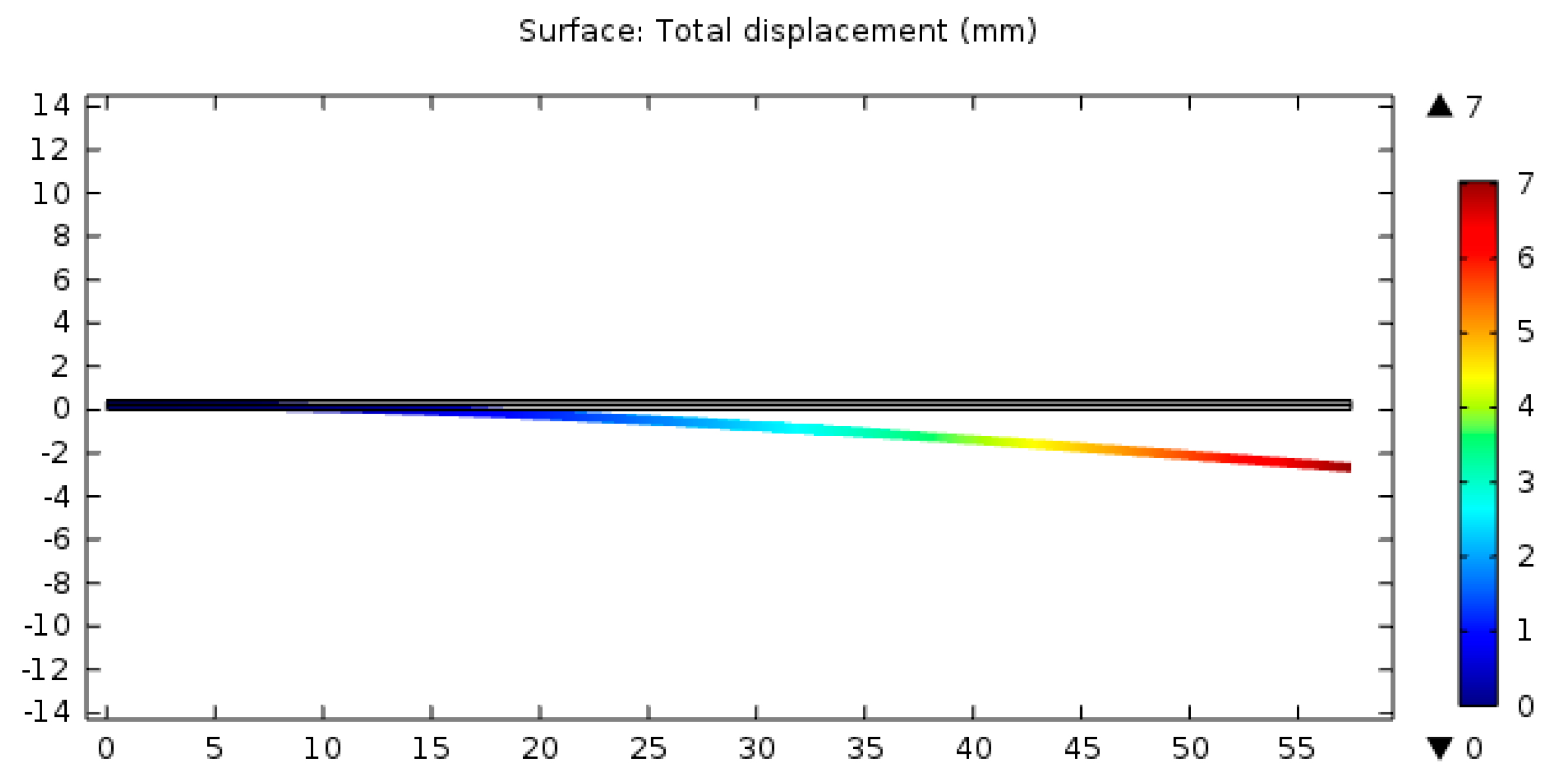
9] measured the tip deformation happened for each case and compared it to paper numerical results using COMSOL Multiphysics as shown in
Figure 13 and
Table 2. The comparison showed a variation of 4% from the propsed numerical model and the both two analytical solutions, and this is can be justified as a two-dimensional (2D) COMSOL Multiphysics model.
Table 4.
Results comparison between Park & Moon [
9], Wang & Cross [
10] and paper numerical model (COMSOL Multiphysics) at different tip forces and applied voltages.
Table 4.
Results comparison between Park & Moon [
9], Wang & Cross [
10] and paper numerical model (COMSOL Multiphysics) at different tip forces and applied voltages.
| Inputs |
Outputs |
| Tip Force, N |
Parallel connection Voltage Difference, V |
Numerical Tip Deformation, mm |
Park & Moon Tip Deformation, mm |
Wang & Cross Tip Deformation, mm |
| 0 |
0 |
0 |
0 |
0 |
| 1 |
0 |
7.023 |
7.79 |
7.79 |
| 10 |
0 |
70.23 |
77.96 |
77.96 |
| 0 |
1 |
0.019 |
0.016 |
0.016 |
| 0 |
10 |
0.19 |
0.16 |
0.16 |
| 10 |
10 |
70 |
77.8 |
77.8 |
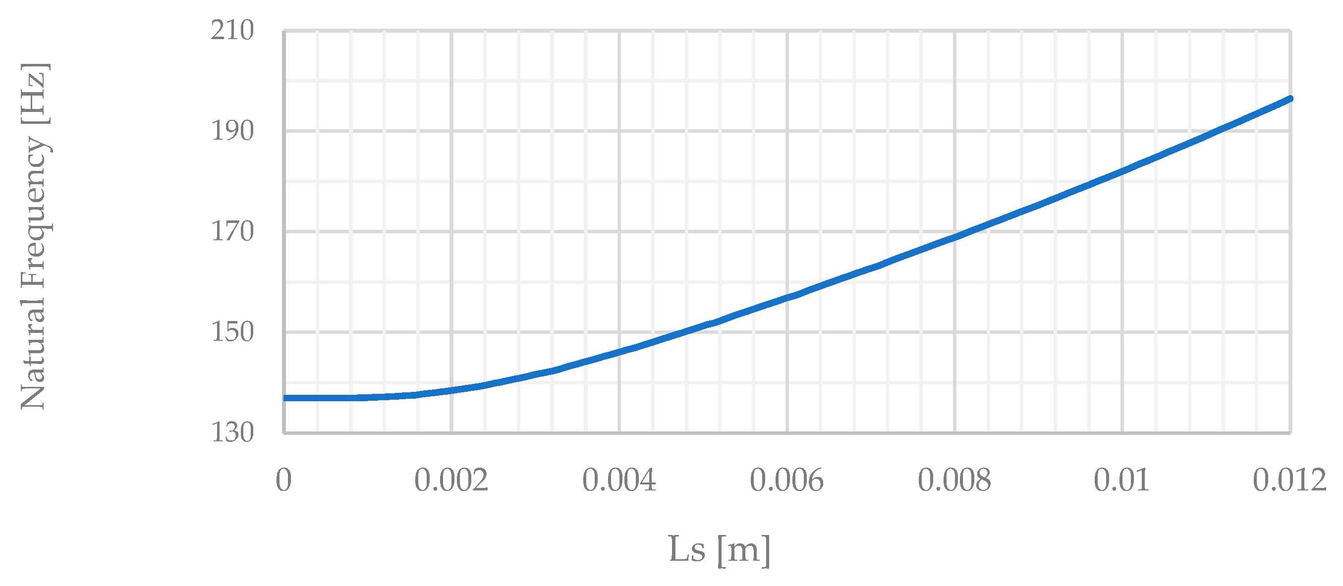
According to the generated COMSOL Multiphysics model, we ran the model 100 times between the manufacturer clamps spots mentioned from -6 mm till +6 mm of total 12 mm, at each point from the 100 points we measured the new natural frequency of the harvester (MIDE - PPA-1021), Figure 16 shows the relation between support position from root (ls) and natural frequency of the beam.
Figure 14.
(a) Relation from COMSOL Multiphysics model between support position from root (
ls) and natural frequency of beam, (b) Numerical model simulation, live video [
11].
Figure 14.
(a) Relation from COMSOL Multiphysics model between support position from root (
ls) and natural frequency of beam, (b) Numerical model simulation, live video [
11].
In order to automate actively the fitting/equating natural frequency of the beam (fn) with the current driving frequency (ω), a stepper motor with a small microcontroller system were developed to automatically measure and input the current driving frequency (ω) and substitute in equation (3) to calculate the required ls, the stepper motion will move the movable support to this required ls to get the new required natural frequency of the beam (fn) to fulfil resonance.
6. Conclusion
As a conclusion for this study, rotational objects have high energy harvesting characteristics due to the centrifugal forces generated naturally with rotation, of course the centrifugal forces increase with increasing the rotation/driving speed, this centrifugal forces effects the harvester’s stiffness and its natural frequency but not with the same ratio with no proper fitting to keep vibrating at resonance, it was managed to get the required fitting between harvester’s driving frequency and its natural frequency to fulfil the maximum possible energy harvesting by allowing the harvester to vibrate at its resonance at all the study’s speed range. The fitting was made actively by changing the length of the MIDE beam to fit the current driving frequency and this methodology managed to compensate the un-complete self-fitting phenomena due to the centrifugal force generated from the rotation.
Reaching maximum possible harvested energy is possible by using the proper optimization methodology, off course we can’t constrain the spinning system to rotation at certain speed but we can do whether active or passive system that can help the harvester’s natural fits the current driving rotational frequency, which will lead to resonance vibration at different speeds.
Author Contributions
Conceptualization, Mohammed Hedaya and Mohamed Elhadidi.; methodology, Mohammed Hedaya and Mohamed Elhadidi; software, Mohamed Elhadidi; validation, Mohammed Heday and Taher Elyazied; formal analysis, Mohamed Elhadidi; investigation, Mohamed Elhadidi; resources, Mohammed Hedaya and Mahmoud Z. Ibrahim; data curation, Mohammed Hedaya and Mohamed Elhadidi; writing—original draft preparation, Mohamed Elhadidi; writing—review and editing, Mohammed Heday, Taher Elyazied and Mahmoud Z. Ibrahim; visualization, Mohamed Elhadidi; supervision, Mohammed Heday, Taher Elyazied and Mahmoud Z. Ibrahim; project administration, Mohammed Hedaya; funding acquisition, Mahmoud Z. Ibrahim. All authors have read and agreed to the published version of the manuscript.
Funding
This research work was partially funded by Matching Grant, University of Malay: grant number MG015-2023A.
Data Availability Statement
The data presented in this study are available on request from the corresponding author due to privacy and confidential issues.
Acknowledgments
The authors would like to acknowledge Faculty of Engineering, Ain Shams University for providing facilities and technical support.
Conflicts of Interest
The authors declare no conflicts of interest. The funders had no role in the design of the study; in the collection, analyses, or interpretation of data; in the writing of the manuscript; or in the decision to publish the results.
References
- Gu, L., & Livermore, C. (2010). Passive self-tuning energy harvester for extracting energy from rotational motion. Applied Physics Letters, 97(8). [CrossRef]
- Lee, K., Lim, B. J., Kim, S. H. (2012). Energy Harvesting by Rotation of Wheel for Tire Monitoring System, IEEE.
- Roundy, S. J., and Tola, J. (2013). “An Energy Harvester for Rotating Environments Using Offset Pendulum Dynamics, IEEE.
- Wang, Y., Chen, C., Lin, C., and Yu, J. (2015). A Nonlinear Suspended Energy Harvester for a Tire Pressure Monitoring System, Micromachines, 312-327.
- Joyce, Bryan Steven. (2011). Development of an Electromagnetic Energy Harvester for Monitoring Wind Turbine Blades. master of science thesis for the faculty of the Virginia Polytechnic Institute and State University.
- Y. C. Shuz, W. C. Wang and Y. P. Chang. (2018). Electrically rectified piezoelectric energy harvesting induced by rotary magnetic plucking. Institute of Applied Mechanics, National Taiwan University, Taipei 106, Taiwan, R.O.C.
- T. Narolia, V. K. Gupta and IA Parinov, Erturk, A. and Lin, J. (2020). Design and experimental study of rotary-type energy harvester. Journal of Intelligent Material Systems and Structures 1-10.
- Hailing Fu, Xutao Mei, Daniil Yurchenko, Shengxi Zhou, Stephanos Theodossiades, Kimihiko Nakano, and Eric M. Yeatman. (2021). Rotational energy harvesting for self-powered sensing. Joule 5, 1074–1118, May 19, 2021 1075.
- Park, J., Moon and W. (2005). Constitutive relations for piezoelectric benders under various boundary conditions. Sensors and Actuators, A 117 159–167.
- Wang, Q. and Cross, L. E. (1999). Constitutive Equations of Symmetrical Triple Layer Piezoelectric Benders. ieee transactions on ultrasonics, ferroelectrics, and frequency control, vol. 46, no. 6.
- Hailing Fu and Xutao Mei (2021). Rotational energy harvesting for self-powered sensing. Joule 5, 1074–1118, May 19, 2021.
- Zhonghua Z., Junling C., Yaqi W., Shuyun W., Xinyue K., Hongyan T., Junwu K. (2022). A rotational energy harvester utilizing an asymmetrically deformed piezoelectric transducer subjected only to unidirectional compressive stress. Elsevier Ltd. 2352-4847.
- https://digidigitalmarketing.my.canva.site/daf-znqfh.
|
Disclaimer/Publisher’s Note: The statements, opinions and data contained in all publications are solely those of the individual author(s) and contributor(s) and not of MDPI and/or the editor(s). MDPI and/or the editor(s) disclaim responsibility for any injury to people or property resulting from any ideas, methods, instructions or products referred to in the content. |
© 2024 by the authors. Licensee MDPI, Basel, Switzerland. This article is an open access article distributed under the terms and conditions of the Creative Commons Attribution (CC BY) license (http://creativecommons.org/licenses/by/4.0/).
