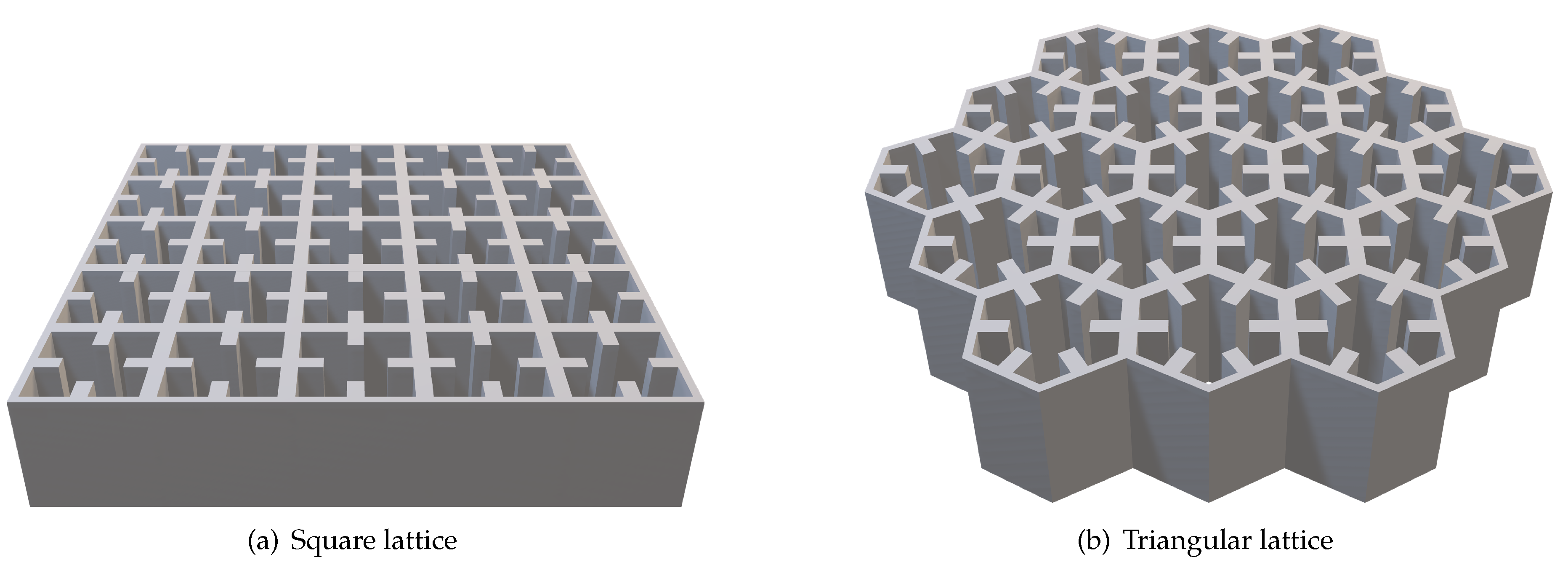
4.1. Quadridge Radiating Elements
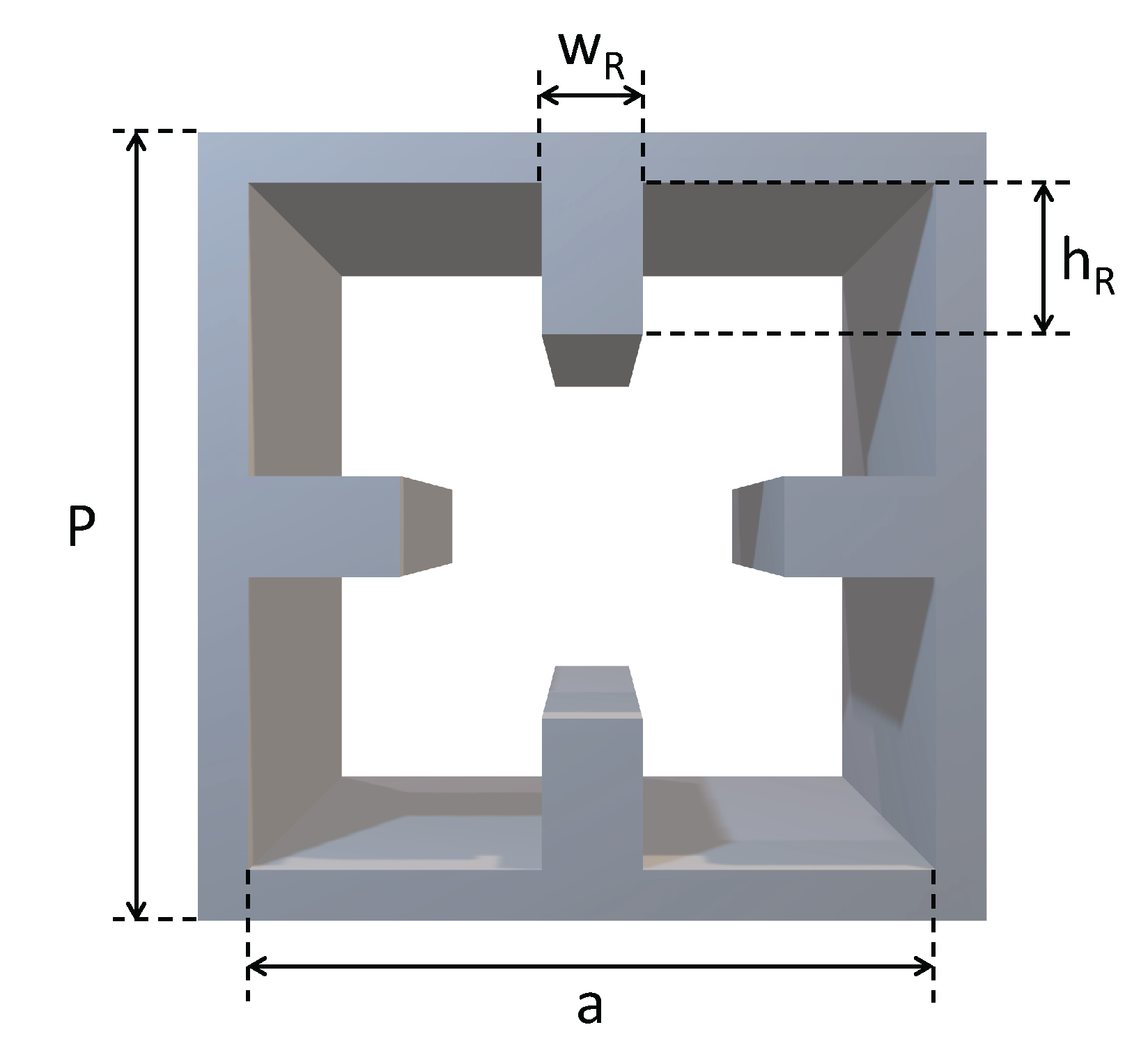
The ARC of the open-ended quadridge waveguide reported in
Section 3.1, whose parameters are summarized in
Table 1, is reported in
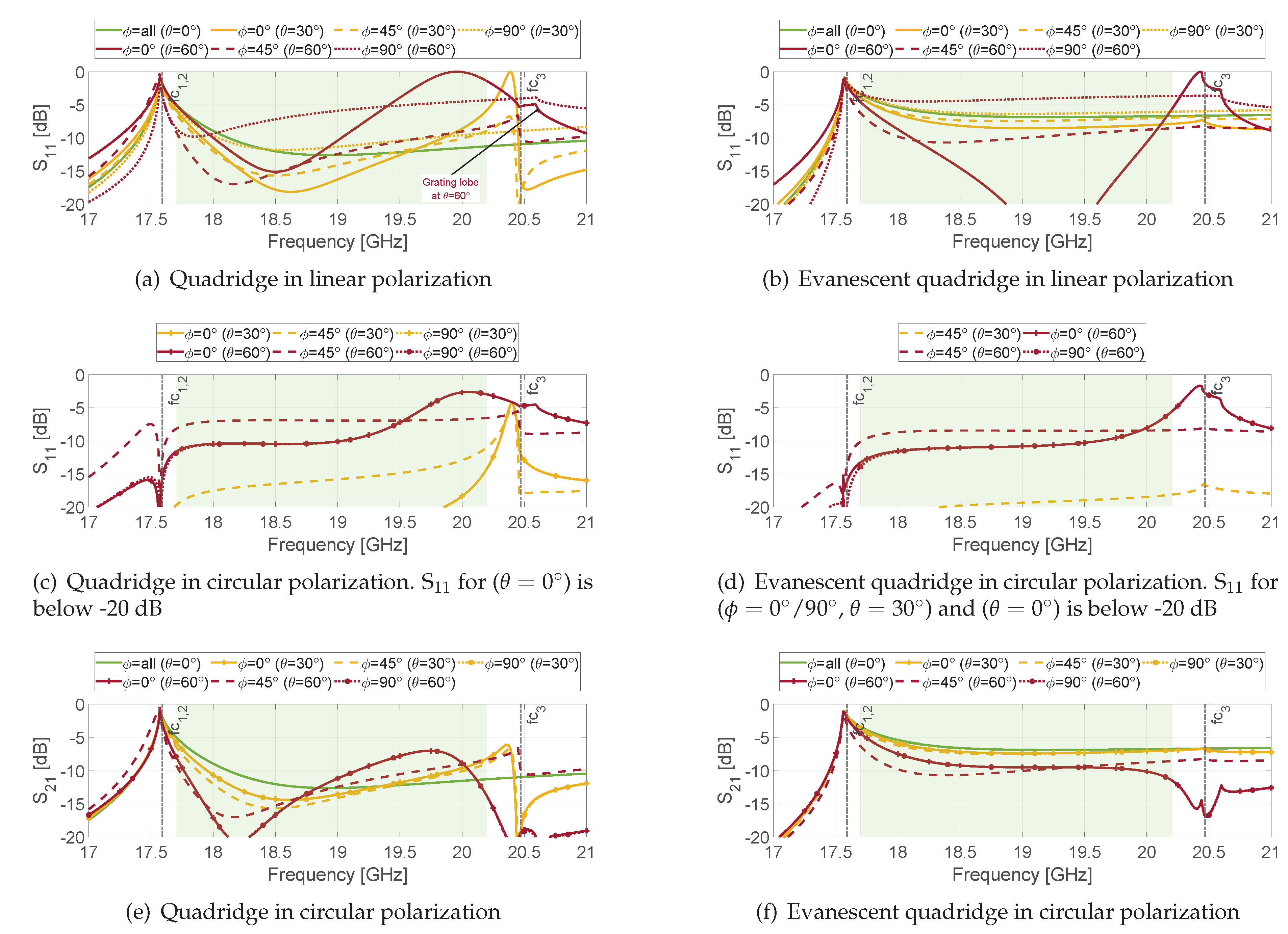
Figure 7(a) for linear polarization. The solid, dashed and dotted lines refer to the E- (
), D- (
) and the H-plane (
), respectively. The line colours identify the scanning angles. The vertical black dash-dotted lines indicate the cut-off frequencies of the waveguide, and the green box highlights the operative bandwidth. The ARC for only one of the two fundamental degenerate modes is shown due to the 90
rotational symmetry along the propagation axis.
It can be seen that the open-ended quadridge waveguide does not provide satisfactory matching level even at broadside (green solid line). This is related to the proximity of the lower cut-off frequency (vertical black dash-dotted line). In addition, when scanning up to 60 in the E-plane (red solid line), a scan blindness is observed at 20 GHz i.e. the signal is completed reflected at this frequency, reducing the bandwidth even further. The other principal plane (dotted red line) instead shows reflection level of about -5 dB in the overall band.
Two sharp features on the S
curves are visible above the upper limit of the frequency band. The first one, located at 20.47 GHz (vertical black dash-dotted line), is due to the higher-order mode of the waveguide. It is related to the waveguide geometry, therefore it is independent of the scan angle. However, it does not appear at
(dotted line) because of the symmetry of the structure i.e the fundamental mode is not coupled to the third one along such a plane (H-plane). The second sharp feature is at 20.61 GHz (black arrow), this is instead due to the appearance of the grating lobes at this frequency (see Equation (
1)).
Concerning the coupling in linear polarization, it is only significant in the D-plane where it reaches -6.5 dB when the scan angle goes up to 60. These curves are not shown for brevity. However, their effect is included in the circular polarization behaviour discussed hereafter.
As far as the ARC in circular polarization is concerned, this scan blindness decreases by almost 3 dB (red solid line in
Figure 7(c)) because, as stated above, only one of the two linear components is completely reflected. The results shown in circular polarization have been calculated taking into account an ideal polarizer (the parameters simulated in linear polarization have been combined according to Equations (2) and (3)).
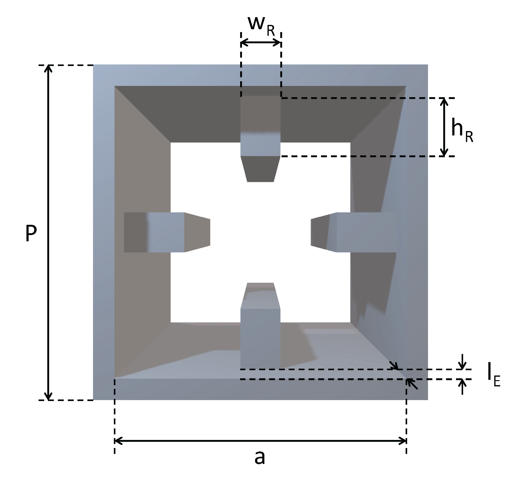
To overcome this scan blindness, a square waveguide section can be placed between the end of the ridges and the aperture (see
Figure 8). Its effect on the E-plane response is shown in
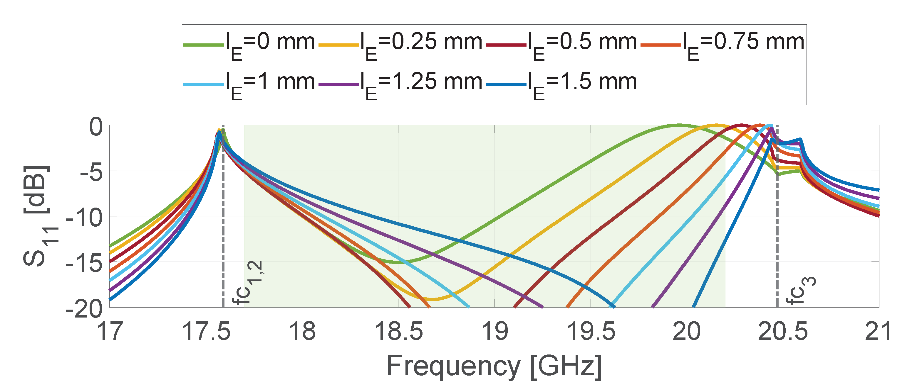
Figure 9 as a function of the length
. The same phenomenon, also called spurious resonance, has been studied in [
5] considering circular polarization. Here, the impact is even more apparent in linear polarization (
Figure 9), where the scan blindness is shifted to higher frequencies and then out of the band increasing the length
. An optimal value of
, 1 mm, has been chosen to achieve the same reflection coefficient value at the two ends of the band (around -5 dB).
The whole phenomenon of the scan blindness reduction is complex because it involves multimodal interaction between the end of the ridges and the aperture. In the quadridge-to-free space discontinuity (
Figure 3), the higher-order mode of the quadridge is strongly excited on the aperture because its cut-off frequency
GHz is close to the upper limit of the frequency band. On the contrary, when the square waveguide section is added (
Figure 8), both fundamental degenerate (TE
, TE
) and higher-order modes (TE
, TM
) are excited at the end of the ridges. However, the TE
and TM
are significantly attenuated (4.3 dB/mm at 20.2 GHz) because their cut-off frequency (31.1 GHz) is far from the operative bandwidth. In this way, the contribution of such higher-order modes to radiation is reduced with respect to the abrupt quadridge-free space interface. It should be mentioned that the TE
is also below cut-off (about 22 GHz). Nevertheless, as shown in
Figure 7(b), such slightly evanescent mode (1.6 dB/mm) does not prevent radiation. However, the overall ARC is higher (at broadside and 30
) with respect to the quadridge element (see
Figure 7(a)). The S
levels are quite acceptable in circular polarization (see
Figure 7(d)) because (due to the polarizer) such reflection coefficient basically depends on the difference between ARCs for the two linear polarizations which is related to the difference response in the two orthogonal planes (see Equation (
2)).
A further increment in will result in a lower and flatter S in circular polarization, but the S will increase in proximity of the lower end of the bandwidth. For this reason, mm can be considered as an optimum value also for circular polarization.
As far as circular polarization is concerned, the evanescent quadridge provides an improvement of about 2-3 dB and overall bandwidth enlargement (
Figure 7(d)) with respect to the nominal one (
Figure 7(c)). The coupling S
shows values equals to -5 dB at the lower end of the band due to the proximity of the cut-off frequency in both designs (
Figure 7(e,f)). The impact of the increased ARC of the evanescent quadridge at low scanning angles is visible on S
(about -6 dB) through all the band.
In conclusion, the quadridge with evanescent section, which does not show the blindness at the expense of a higher reflection coefficient in linear polarization (and higher S in circular), can be suitable for single-pol DRAs, where the port of the unexcited polarization is closed on a matched load (with reduction of the overall efficiency).
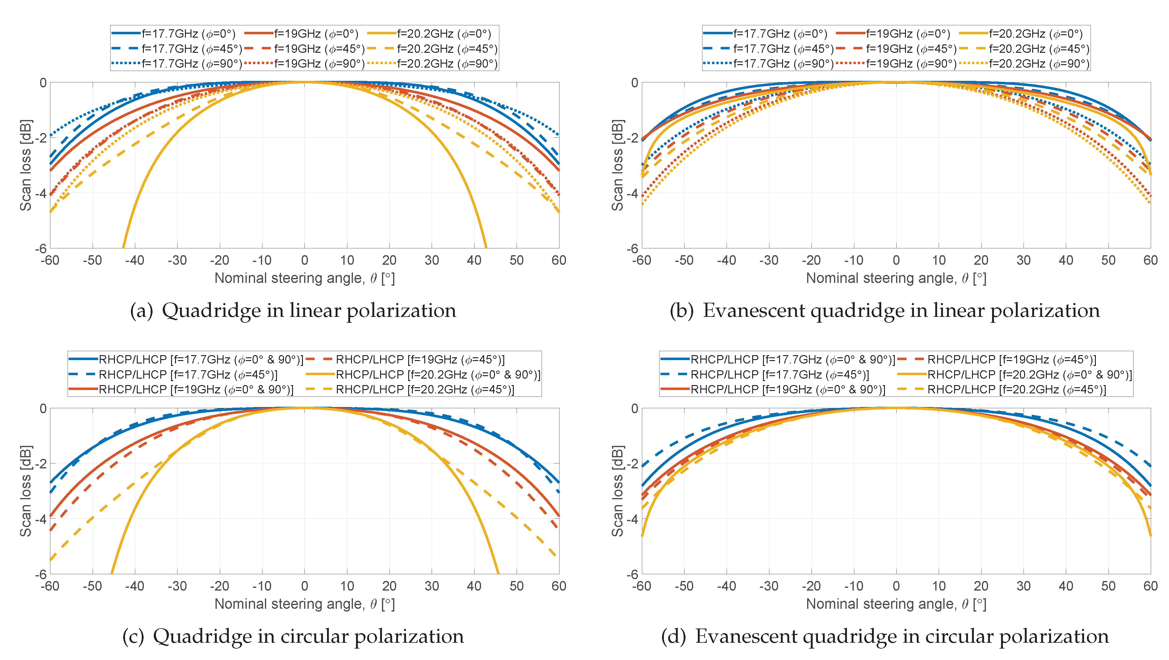
Figure 10 shows the scan loss at the band limits and center frequency when scanning from
to
for both quadridge designs in both linear and circular polarization. The circular polarization data have been computed according to Equations (4) and (6) as a function of the radiated field in linear polarization.
From
Figure 10(a), a maximum difference of 2 dB is observed between planes at 17.7 GHz (blue lines) and 19 GHz (red lines). At 20.2 GHz (yellow lines) the scan loss drops more than 6 dB due to the scan blindness discussed above. The same consideration applies for circular polarization (
Figure 10(c)). When the evanescent section is added (
Figure 10(b)), the drop due to scan blindness at the upper frequency of the band disappears, obtaining values between -2 and -4 dB for all the planes and frequencies. Similar values are visible in circular polarization.
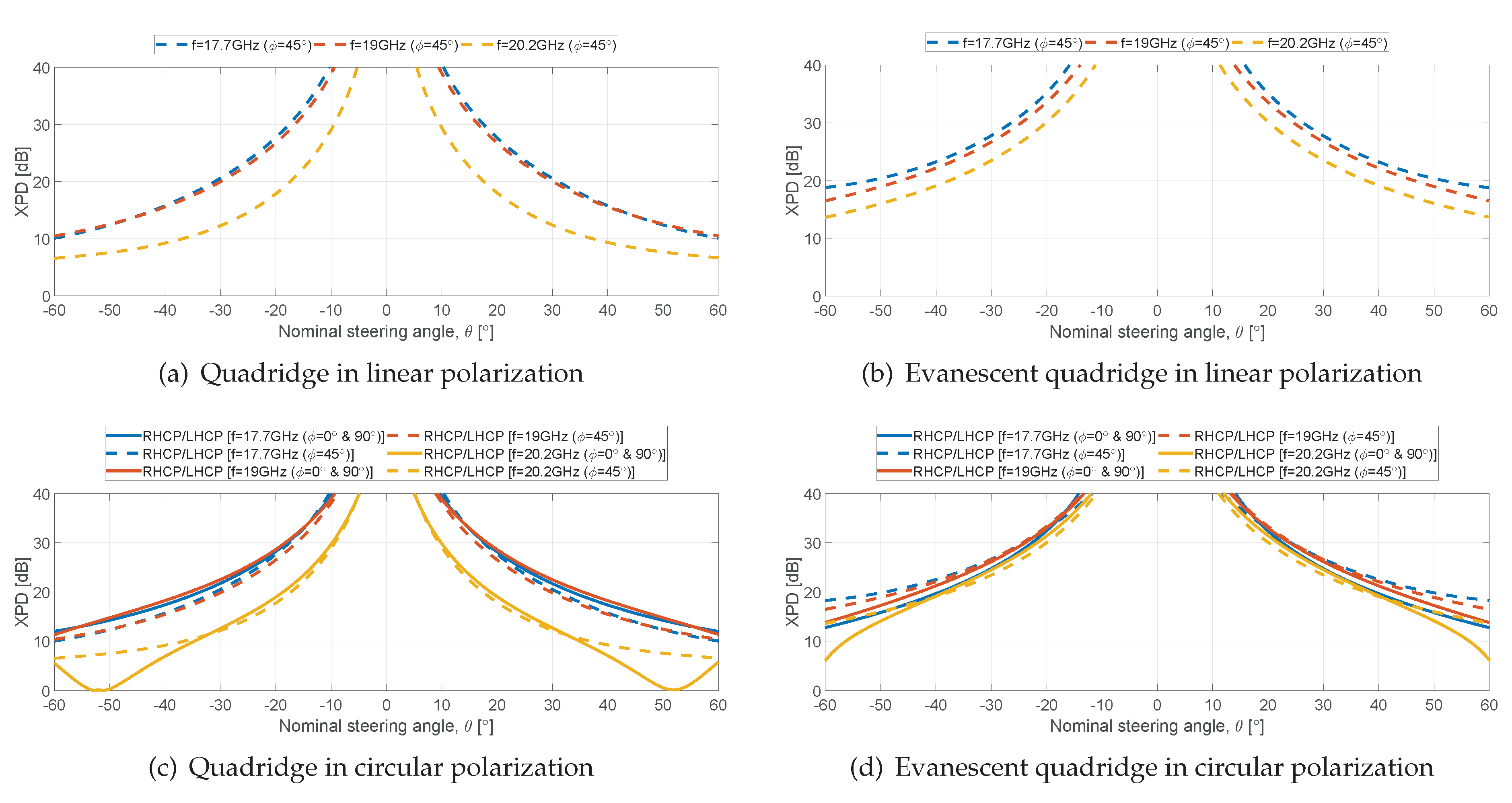
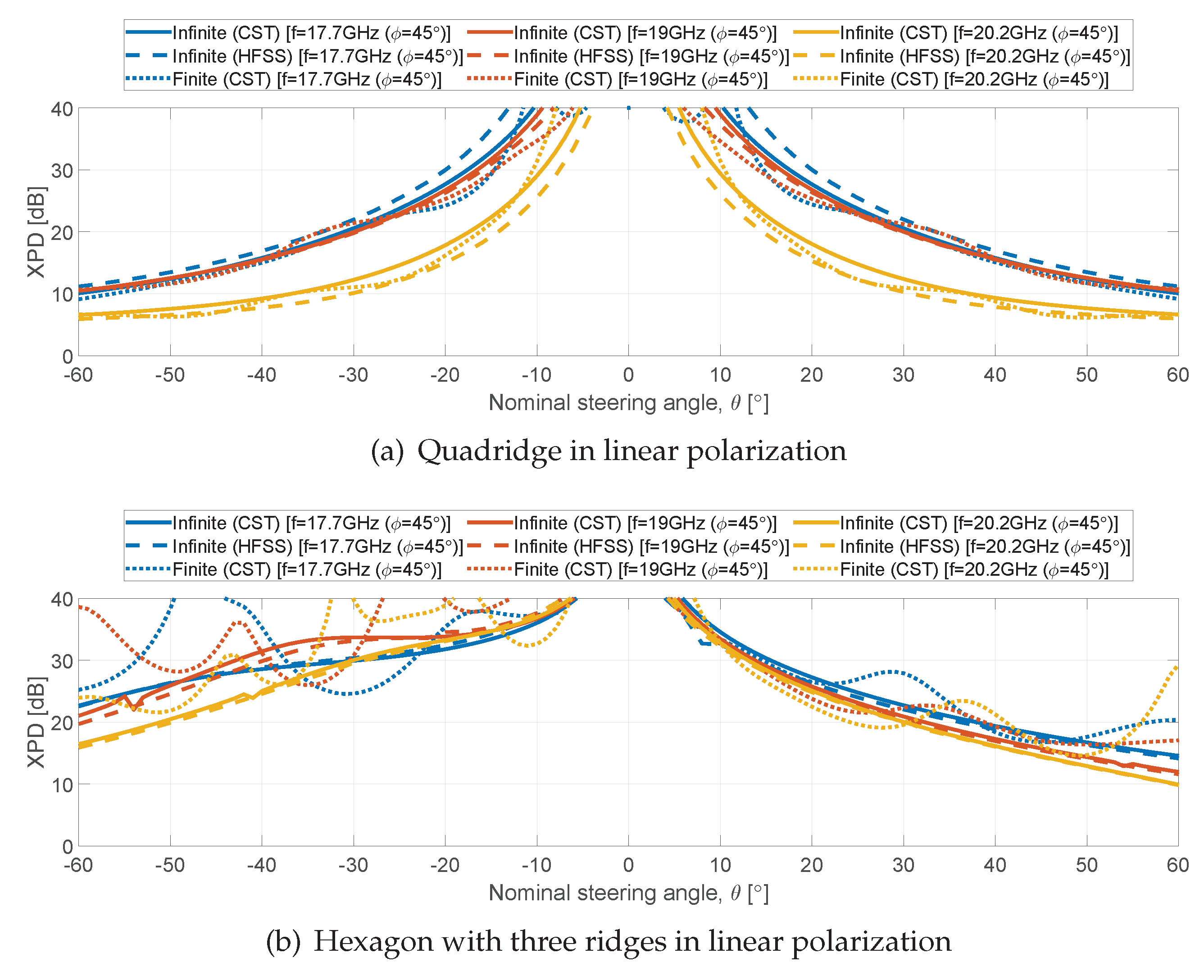
The XPD performance in D-plane (Ludwig 3) is shown in
Figure 11. The E- and H-planes are not reported due to the two-fold symmetry (the simulated values are above 40 dB). Circular polarization data have been computed as the ratio between the Equations (4) and (5), and Equations (6) and (7). The quadridge in linear polarization (
Figure 11(a)) provides values around 10 dB at 17.7 and 19 GHz, and a value of about 7 dB at the upper frequency. The presence of the blindness is clearly visible in circular polarization (
Figure 11(c)), where XPD approaches 0 dB. This happens because one of the two linear components is completely reflected and hence the radiated field is linearly polarized. The values at the scan limits improve for the evanescent quadridge, being higher than 14 dB for the three frequencies in linear polarization (
Figure 11(b)). In terms of circular polarization (
Figure 11(d)), there is a decrease at 20.2 GHz in the planes
. This is due to the different radiation patterns for the two principal polarizations at high scan angles, as it can be seen comparing solid and dotted lines in
Figure 10(b) (see Equations (4)–(7)).
4.2. Hexagonal Ridged Radiating Elements
Differently from the quadridge, where the optimum value (OV) of the ridge dimensions was selected on the basis on the cut-off analysis only, the hexagonal structures allow a larger range of parameters (see
Section 3.2). For this reason, full-wave analyses have been carried out to determine the OVs for the three and six ridges configurations.
Figure 12 shows the contour plots of ARC averaged on scan range as a function of the ridge parameters. For both configurations, where the optimal region is apparent, the selected OVs are shown in
Table 2. The manufacturing constraint of 1 mm for the ridge width has been also considered. The optimum values for the hexagon with three ridges (
Figure 12(a)) are 1 mm and 1.75 mm for width and height, respectively. The resultant cut-off frequencies are 17.4 GHz and 30.7 GHz for the fundamental and higher-order modes. In the case of six ridges (
Figure 12(b)), optimum values are 1 mm and 1.7 mm for width and height, respectively. In this case, cut-off frequencies are 17.4 GHz and 21.7 GHz for the fundamental and higher-order modes.
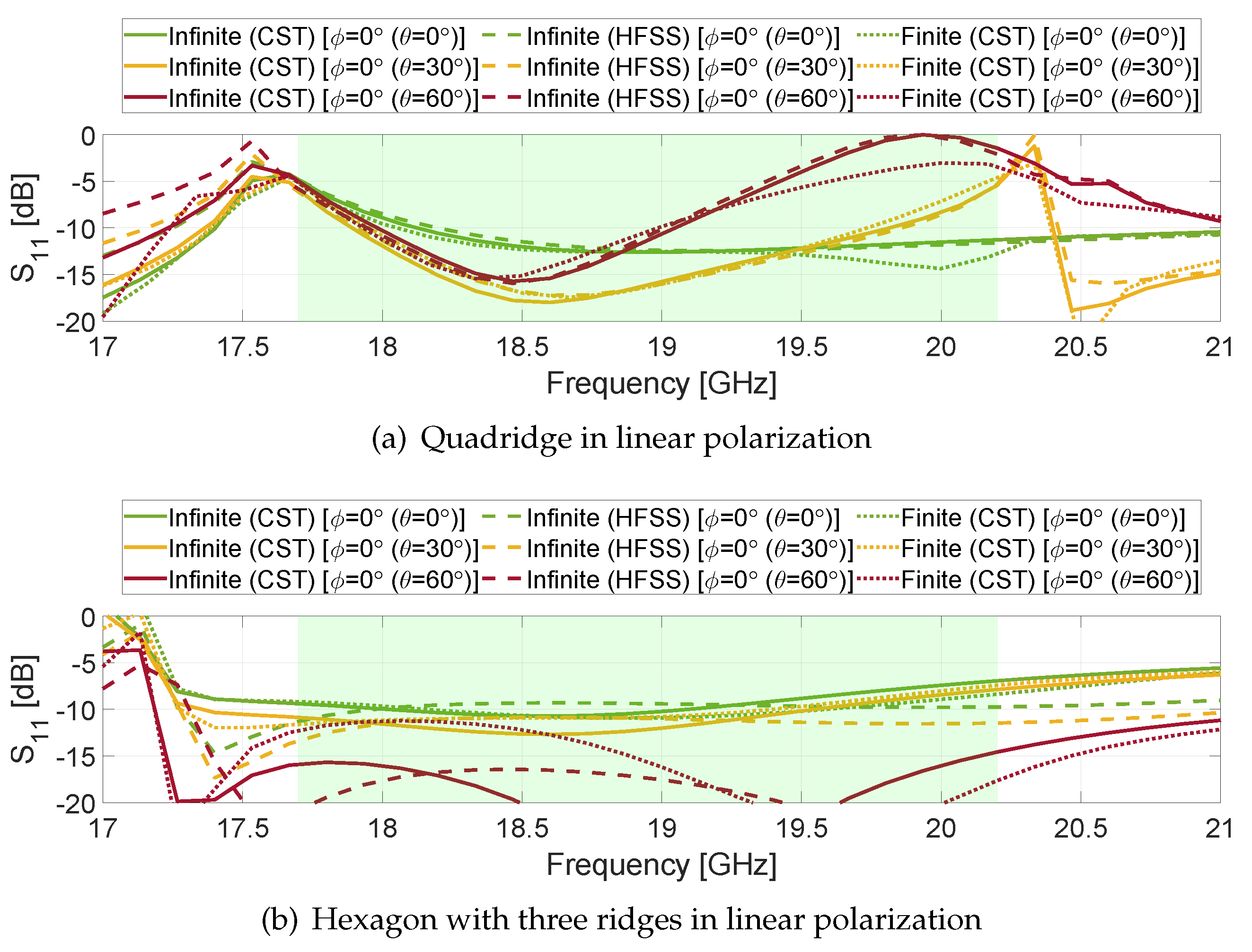
The S-Parameters of both hexagonal designs in the E-, D- and H-planes at different scan angles are reported in
Figure 13(a,b). No scan blindness is visible due to the high cut-off frequency of the third mode. The worst value is around -4 dB in the H-plane when scanning to the 60
limit (dotted red line). For smaller scan angles (green and yellow lines), the six-ridges solution provides an improvement of about 2 dB in E- and D-planes above 18.5 GHz. Scattering parameters for the other fundamental mode (S
, i.e. other polarization) are similar to S
, therefore they are not reported for brevity. S
in linear polarization (not shown) is in the order of -10 dB and its effect is accounted in the circular polarization data.
As far as the circular polarization is concerned, both hexagonal designs (
Figure 13(c,d)) have similar behaviour. The three-ridges solution has a flatter behaviour due to the higher cut-off frequency of the third mode. The overall levels are similar to the evanescent quadridge one
Figure 7(d). The coupling in circular polarization for the hexagon with three ridges is shown in
Figure 13(e). The values are below of -10 dB for scanning angles up to 30
for each principal plane. A value of about -5 dB is obtained at the scanning angle limit for
(dotted red line). Comparing
Figure 13(c,d), it can be observed that the six-ridges solution exhibits worse performance at the upper frequency limit of the band (i.e. some bandwidth reduction). Again, this is due to lower cut-off frequency of the higher-order mode (21.7 GHz) with respect to the three-ridges counterpart (30.7 GHz). Similar values are obtained for the coupling in circular polarization of the six ridges configuration (
Figure 13(f)). In this case, there is less variations between planes. The worst value is obtained at 60
for
(dotted red line), being -5 dB at higher frequencies.
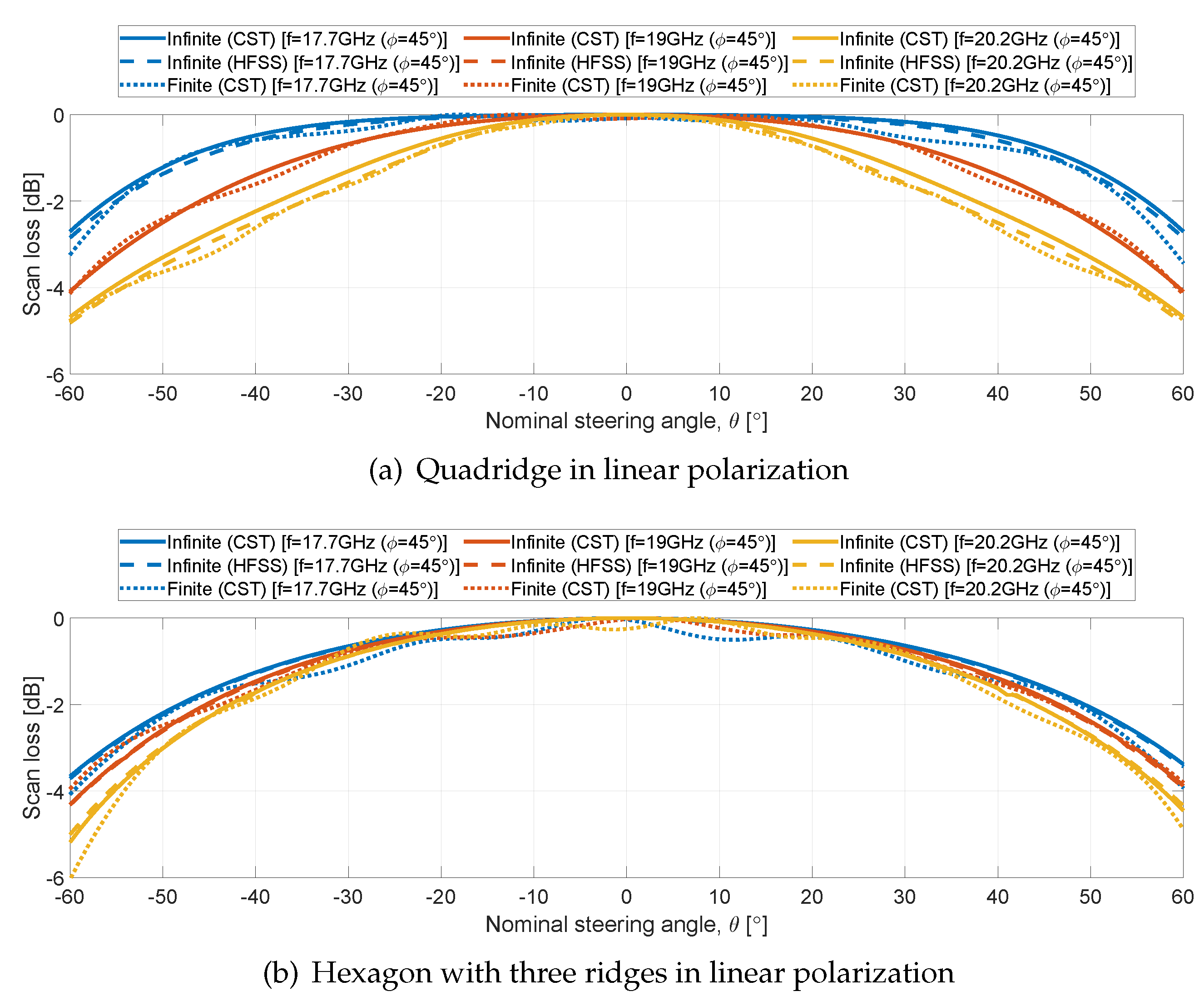
Concerning the scan loss,
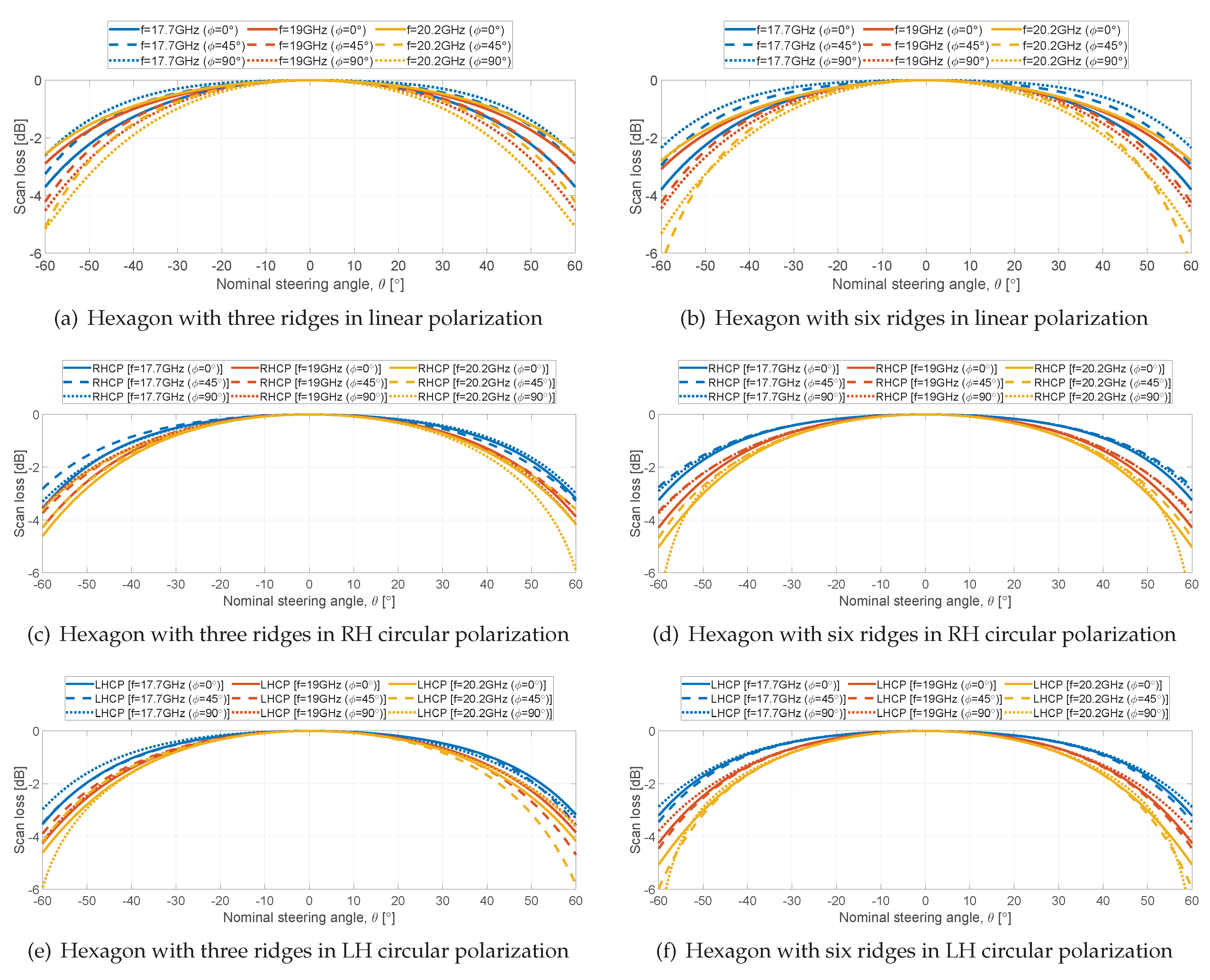
Figure 14 shows the results of both hexagonal designs within the scan range of -60
to 60
in both linear and circular polarization. In terms of linear polarization, both hexagonal apertures (
Figure 14(a,b)) show a decay between 2.5 and 3.5 dB at
in the E-plane for the three considered frequencies (solid lines). These values increase up to 5 dB for the hexagonal aperture with three ridges and up to 6 dB for the hexagonal aperture with six ridges, in both D- and H-planes (dashed and dotted lines).
Differently from the quadridge structure, the hexagonal waveguide apertures do not have 90
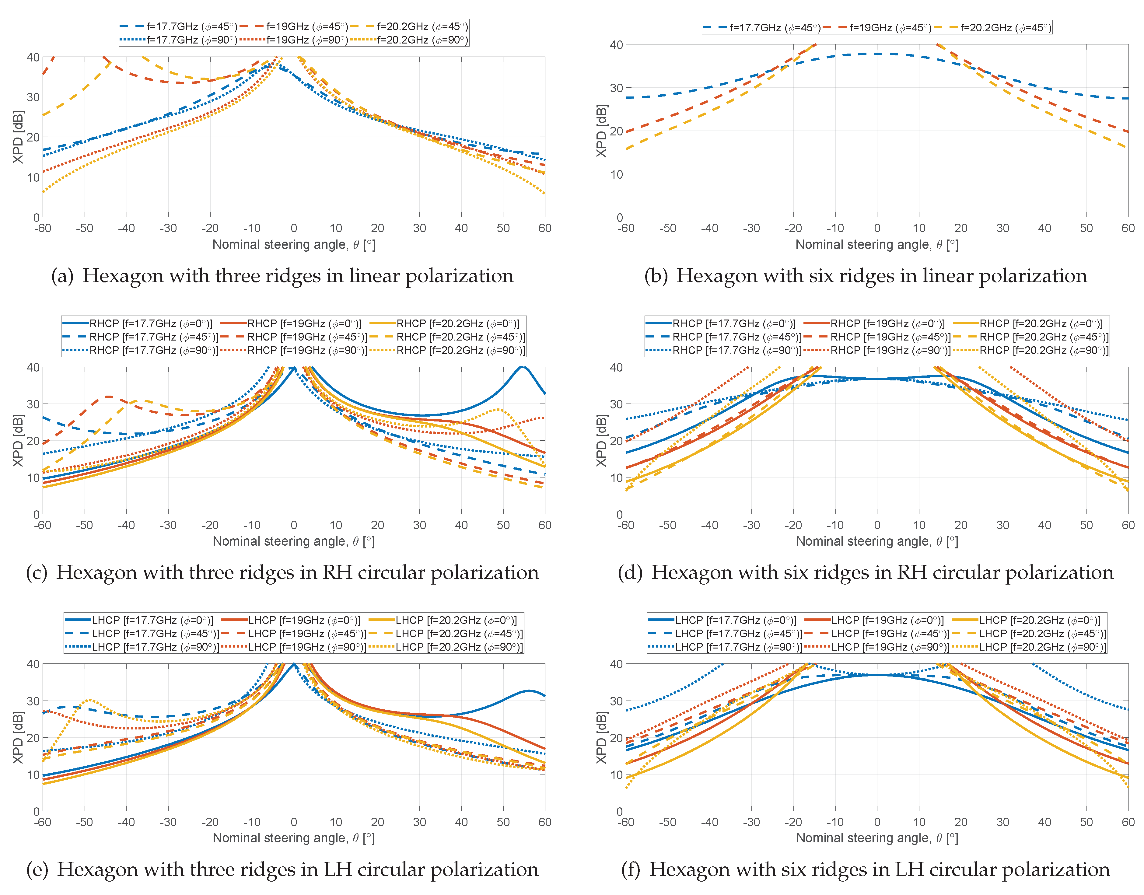
rotational symmetry. Therefore, a full set of scan loss and XPD data is provided for both left hand (LH) and right hand (RH) circular polarization. For both solutions, the scan loss ranges from 3 to 6 dB (
Figure 14(c,e)). Minor differences are visible between the two circular polarizations.
The XPD is reported in
Figure 15. The curves for the three-ridged aperture are not symmetrical along the scan range (fig:XPD-lineal-hexagon-threeridges,fig:XPD-circular-hexagon-threeridges1,fig:XPD-circular-hexagon-threeridges2) due to the one-fold symmetry of the geometry. Symmetrical curves are instead observed for the six ridges solution thanks its two-fold symmetry. XPD values ranging from 8 to 10 dB are observed at the scan limits. As already discussed for the quadridge, these values are related to the different behaviour of the structure for the two principal polarizations along the scan planes. It should be noted that the complete scan loss and polarization analyses reported in fig:scanloss-hexagon,fig:XPD-hexagon are required to appreciate the performance variation along the various planes for both polarizations and asses the worst cases.
4.3. Performance Comparison
The performance of the proposed designs is listed in
Table 3. The scan angle of 50
is also reported to provide direct comparison to the literature data. All the data refer to circular polarization.
Reference [
5] reports an EQA with a matching section providing acceptable reflection and coupling up to
within a bandwidth of 4.5%. The worst case XPD level is only 8 dB.
For the radiated elements presented in this work, no matching section is included. In this way, the reported data show the intrinsic performance of such radiating apertures (open-ended waveguides) i.e. the performance that can be achieved with minimum complexity. The reported data can be used as a reference for the future design of more complex elements including matching discontinuities.
The quadridge without evanescent section has been reported for completeness. However, it is apparent that the scan blindness impairs the overall performance in terms of both reflection (-4 dB) and XPD (0 dB) for high scan angles.
The evanescent quadridge instead provides good performance in terms of matching (-11 dB), scan loss (2 dB) and XPD (14 dB) within 13.2% bandwidth up to 50
scan angle. The coupling S
is -3 dB at the lower limit of the band. Such level is actually -8 dB above 18.5 GHz (see
Figure 7(f)).
The hexagon with three ridges reports an improvement on the coupling S (-6 dB) with respect to the evanescent quadridge up to 50 scan angle. Moreover, acceptable values have been obtained for scan loss (3 dB) and XPD (11 dB).
The hexagon with six ridges shows the best performance in terms of coupling S (-8 dB). The XPD (12 dB), scan loss (3 dB) and matching S (-10 dB) are comparable to the three ridges. The quadridge provides better performance in terms of XPD.
The performance for scan angles of 60 is not satisfactory for all the elements. The coupling is above -10 dB even at 50 scan angles. From these considerations, we can conclude that such elements can be suitable for single polarized DRAs (which, to the best of the author’s knowledge are the currently adopted configuration nowadays in LEO satellites) operating up to 50 scan angles, when the unexcited port is closed on a matched load. This will reduce the element radiation efficiency. However, it will provide a smooth frequency response (without spurious resonances/spikes).
