1. Introduction
With the intensive and saturated development and utilization of surface space, underground space is the key field of urban development in the future [
1]. The construction method of tunnel full face road header is one of the efficient mining methods that meet the requirements of intelligence and mechanization [
2]. It mainly uses the face disk hob to roll rock. When the uniaxial compressive strength of rock is large, the rock hardness is close to the Indentation hardness of the metal at the edge of the hob, and the hob is severely worn and invalid, the economic and time costs of hob maintenance limit the construction efficiency of tunneling machines [
3], so how to effectively reduce the wear of hobs is the focus of scholars’ attention. Water jet technology has been widely used in the development of underground space resources and energy due to its flexible transmission and non-contact rock breaking characteristics [
4,
5,
6,
7]. At the same time, water jet technology can effectively couple mechanical tools for joint rock breaking [
8]. Liu et al. used experimental and simulation methods to reveal the parameter influence law and damage mechanism of water jet combined with mechanical cutting tools for crushing concrete [
9,
10]. Wang et al. proposed an ultra-high pressure water jet groove cutting method to release stress in response to the problem of increased rock strength under high ground stress [
11]. Luo et al. revealed through experiments the influence of water jet pre-cutting on the rock breaking mechanism of the rolling cutter [
12], Li et al. analyzed the influence of water jet cutting trajectory on the rock breaking effect [
13], Jiang et al. studied the influence of confining pressure and water jet cutting on the rock breaking results of the cutter [
14], Cheng et al. studied the influence of water jet cutting depth and spacing on the rock breaking specific energy and effect [
15], Liu et al. analyzed the influence of water jet on the cutting force of the cutting tooth through finite element simulation [
16].
From the above, it can be seen that water jet pre crushing can effectively improve the rock breaking efficiency of cutting tools, and ultra-high pressure water jet [
17] and abrasive water jet can effectively damage hard rock. However, the maintenance of ultra-high pressure water jet is difficult and bulky, and the high-speed cutting ability of abrasive water jet is insufficient, and an additional abrasive transport system needs to be added. In response to these shortcomings, Lu et al. proposed a pressurized pulse water jet rock breaking technology [
18,
19], which uses the water hammer impact wave of the pulse jet to damage hard rock. Initial experiments have shown that it can effectively break hard rocks such as granite [
20,
21,
22]. The boost chamber is the jet energy output chamber, and the output pressure of the boost chamber determines the ability level of the jet to break rocks. The nozzle diameter provides a payload for the establishment of the boost chamber pressure [
23,
24], and the nozzle affects the development and evolution of the subsequent jet flow field [
25,
26,
27,
28]. However, the influence of nozzle diameter on the pressure characteristics of the pressurized chamber is not yet clear. In response to the above issues, the authors analyzed the trend of the influence of nozzle diameter, a key factor, on the pressure characteristics of the pressurized pulse water jet pressurized chamber through theoretical derivation and experimental research, providing a research basis for the subsequent use and development of pressurized pulse water jet crushing of hard rock.
2. Pressure Boosting Theory of a Pressurized Pulse Water Jet Generator
2.1. Equations of Motion of Generator
In order to achieve ultra-high pressure pulse output of low-pressure driving fluid in engineering sites, the author’s team proposes to use fluid pressurization technology and hydraulic self-commutation to achieve self-commutation and periodic pressurization of the fluid, thereby achieving pressure doubling and intermittent injection of the fluid, which is a pressurized pulse water jet generation device. Conversion of low pressure and large flow continuous fluid to high pressure (ultra-high pressure) and small flow pulsed fluid through a pressurized pulsed water jet generator.
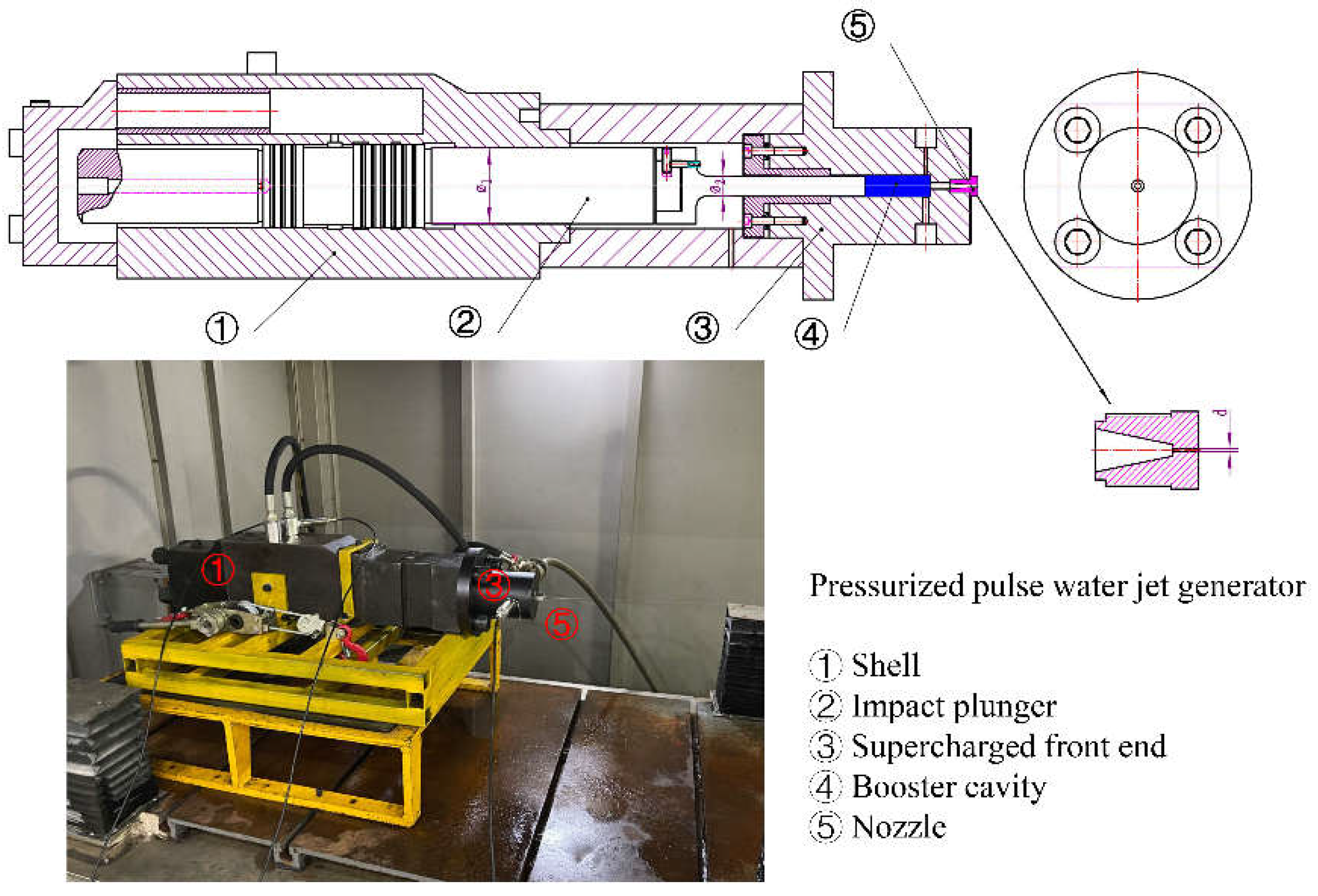
The structure and physical diagram of the pressurized pulse water jet generator device are shown in
Figure 1. The generator mainly includes a shell, an impact plunger, a boost front end, a boost chamber, and a nozzle. The equivalent diameter of the rear end of the impact plunger is
φ1, mm; The equivalent diameter of the front end is
φ2, mm; The nozzle diameter is
d, mm.
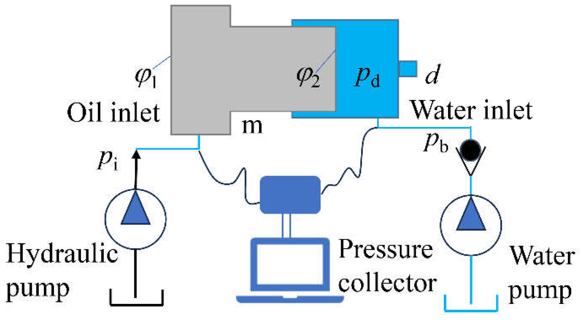
Further simplify the pressurized pulse water jet generator shown in
Figure 1 and obtain a simplified schematic diagram of the pressurized pulse water jet generator, as shown in
Figure 2.
From
Figure 2, it can be seen that the squeezing plunger moves forward to squeeze the fluid in the boosting chamber. The fluid is pressurized and sprayed through the nozzle, and the squeezing plunger moves backward. The fluid replenishes water to the boosting chamber and assists in pushing the plunger backward.
When squeezing the plunger forward, there are:
In the formula, pi is the inlet oil pressure, MPa; pd is the pressure of the booster chamber after boosting, MPa; f is the frictional resistance of the plunger, N; m is the total mass of water in the plunger and booster chamber, kg; B is viscous drag coefficient; v is the movement speed of the extrusion plunger, m/s.
When the squeezing plunger moves smoothly, the frictional resistance of the plunger, the viscous resistance of the fluid, and the acceleration of the plunger are ignored. When the diameter of the nozzle is small enough, there are:
Define the theoretical boost ratio
br: the ratio of the fluid pressure in the boost chamber to the inlet oil pressure of the generating device, during the process of the impact plunger squeezing the fluid in the boost chamber, then
2.2. Critical Nozzle Model
As can be seen from the above, the function of the pressurized pulse water jet generator is to transmit hydraulic power and convert and control the speed and form of movement of the plunger. Set the input hydraulic power to
Ni, the input fluid power to
Nb, and the output booster chamber fluid power to
Nd, then the energy conversion efficiency
η of the booster pulse water jet generator is:
For a pressurized pulse water jet generator, the hydraulic power is proportional to the product of the pressure and flow rate of the working fluid, namely:
In the formula, K is the proportional constant; Qi is the input flow rate of the hydraulic pump, L/min; Qb is the input flow rate of the water pump, L/min; pb is the input pressure of the water pump, MPa; Qd is the output flow rate of the booster chamber, L/min.
The simultaneous equations (5), (6), (7), and (8) have:
If the energy loss during the energy conversion process of the pressurized pulse water jet generator is ignored, and the input energy of the water pump is much smaller than that of the hydraulic pump, it can be obtained from equation (9):
When the nozzle flow channel is a circular tube structure, then:
In the formula, v is the jet velocity, m/s; p1 is the static pressure inside the nozzle, MPa; p2 is the external static pressure of the nozzle, MPa; ρ is the water density, kg/m3; d1 is the inner diameter of the nozzle, mm; d2 is the outer diameter of the nozzle, mm.
In equation (12), v is the cross-sectional fluid velocity, m/s; A is the cross-sectional area, m2.
By taking
ρ=998 kg/m
3 and combining equations (11) and (12), it can be obtained that:
Then, equations (4), (10), and (13) can be used to obtain:
In equation (14), dc is the critical diameter of the nozzle under the conditions of theoretical flow rate and theoretical boost ratio in the boost chamber, mm; pm is the peak pressure that can be achieved under the theoretical boost ratio conditions of the boost chamber, MPa. The critical diameter of the nozzle under different boost chamber peak pressure conditions can be obtained through equation (14) above.
3. Experimentation
3.1. Experimental System
As shown in
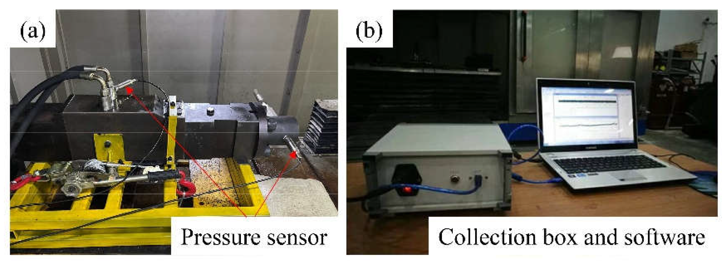
Figure 3, a pressure acquisition system is built on the basis of a pressurized pulse water jet generator. The pressure collection system mainly consists of three parts, including the power supply part, the pressurized pulse water jet generator, and the pressure collection device.
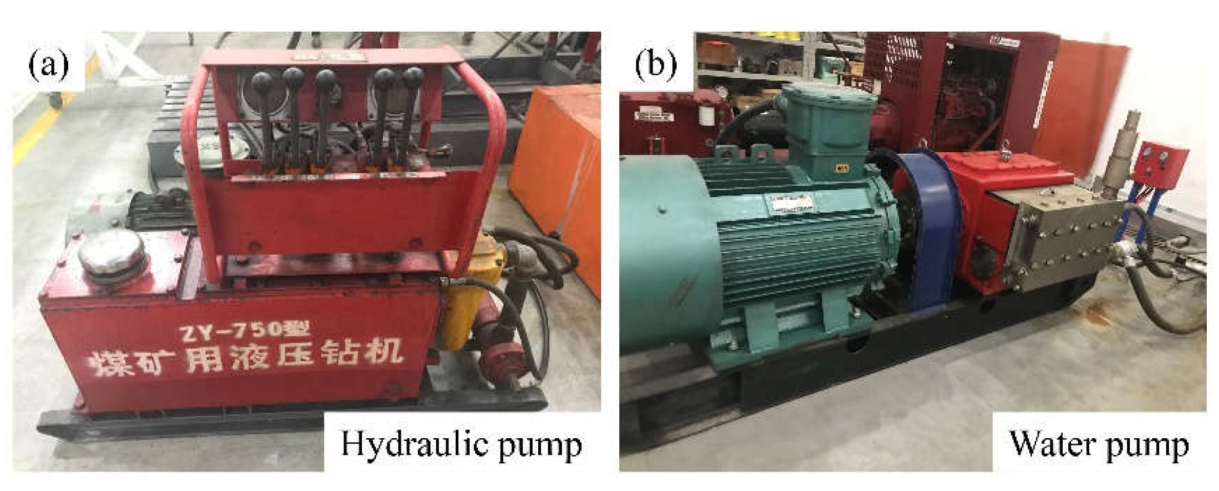
The power supply mainly includes hydraulic supply and water supply. The hydraulic oil pump is responsible for providing hydraulic power source for the impact plunger and reversing slide valve, with a rated pressure of 25 MPa and a rated flow rate of 40 L/min. The water pump supplements the fluid in the booster chamber with a rated pressure of 56 MPa and a rated flow rate of 200 L/min. The physical diagram of the power source is shown in
Figure 4.
The data acquisition system mainly consists of pressure sensors, signal acquisition boxes, and acquisition software, responsible for collecting inlet and outlet oil pressure and boost chamber pressure. The sampling frequency is 100 Hz, the range is 250 MPa, and the sampling error is ± 0.1%.
The pressurized pulse water jet generator mainly includes a boosting unit and a reversing unit, as shown in
Figure 1. The equivalent diameter of the rear end of the impact plunger of this prototype is φ1=53 mm; The equivalent diameter of the front end is φ2=22 mm, and the theoretical boost ratio is br=5.8.
3.2. Selection Basis for Main Control Parameters
The driving pressure is set to 0-15 MPa. Due to the theoretical and practical scenario of the pressurized pulse water jet generator being rock fragmentation in deep space, considering the safety of underground space operations and the rated capacity of the on-site hydraulic pump station, the low-pressure drive of the pressurized pulse water jet generator is selected.
The initial pressure setting range is 0-15 MPa. This is because the theoretical design of the pressurized pulse water jet generator is an integrated fluid route of driving and boosting, which means that the only fluid power source supplies fluid to the driving unit and boosting unit respectively. Therefore, the selection range of initial pressure is synchronized with the driving pressure.
The nozzle diameter setting range is 0.3 mm, 0.5 mm, 0.8 mm, and 1.0 mm. When pi=14 MPa, pm is about 80 MPa. By substituting the theoretical boost ratio br=5.8 and Qi=40 L/min into equation (14), dc=0.6mm can be obtained. That is, under fixed driving parameters in this experiment, the theoretical critical diameter of the nozzle is 0.6mm. In order to comprehensively analyze the influence of nozzle diameter on pressure pulsation characteristics, 0.3 mm and 0.5 mm were selected for the inner nozzle of the critical diameter, and 0.8mm and 1.0mm were selected for the outer nozzle of the critical diameter.
3.3. Experimental Scheme
Conduct experiments with fixed driving pressure and initial pressure in the boost chamber, with nozzle diameter as the independent variable and fluid pressure characteristics in the boost chamber as the dependent variable. The experimental plan is shown in
Table 1 below.
Experimental process:
① Install and fix a pressurized pulse water jet generator, and install pressure sensors at the oil inlet, return port, and boost chamber respectively;
② Start the water pump, adjust the pressure of the water pump to the set inlet pressure, and maintain stability;
③ Start the oil pump and adjust the pressure of the oil pump to the set inlet pressure. At this point, the pressurized pulse water jet generator begins to operate, and the plunger periodically compresses the fluid in the pressurized chamber, causing periodic changes in the fluid pressure in the pressurized chamber;
④ Conduct experiments in the order shown in
Table 1 and collect pressure data of the booster chamber under different nozzle diameters.
3.4. Error Analysis
To ensure the effectiveness of pressure collection, after the sensor collects stable pressure, three consecutive pressure data segments are selected for average post pressure analysis.
4. Results and Discussion
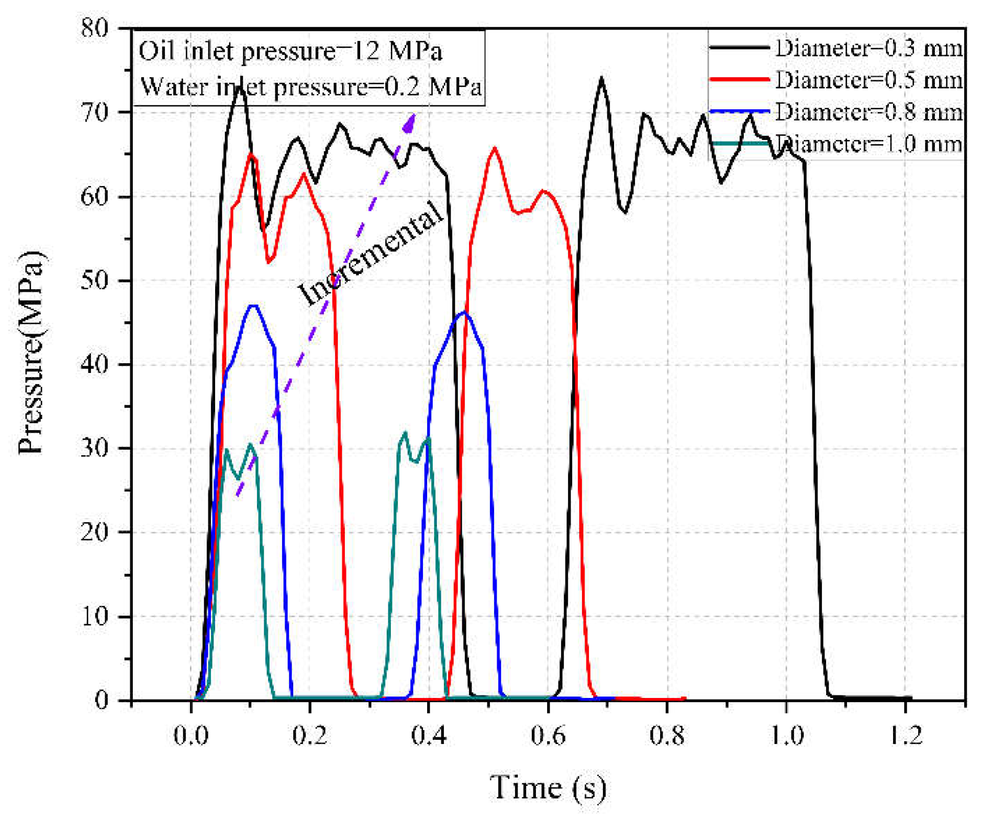
Collect pressure data for different nozzle diameters under different operating conditions when the inlet pressure is 12MPa and the inlet pressure is 0.2MPa, as shown in
Figure 7.
From
Figure 7, it can be seen that when the nozzle diameter is less than the critical pressure, as the nozzle diameter increases, the peak pressure change in the booster chamber is relatively weak, and the duration of a single cycle tends to decrease. When the nozzle diameter is greater than the critical pressure, as the nozzle diameter increases, the peak pressure of the boost chamber sharply decreases, and the duration of a single cycle rapidly decreases.
4.1. Characteristics of Pressure Pulsation in the Booster Chamber
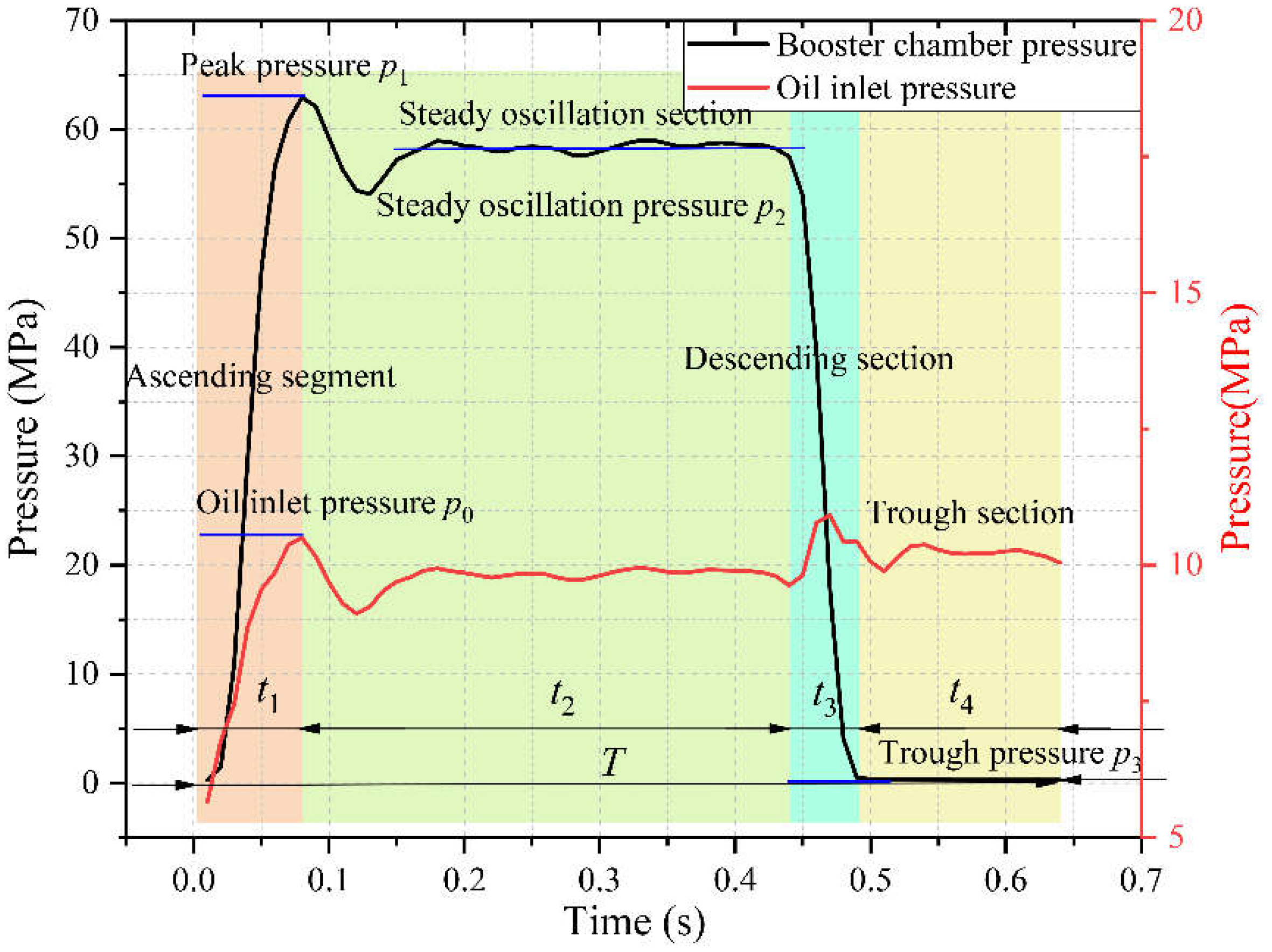
To further reveal the influence mechanism of driving parameters and nozzle parameters on the fluid characteristics of the booster chamber, the fluid pressure in the booster chamber is divided into domain values according to specific pressure nodes in the stroke and return stages, and the transient response performance indicators of pressure pulsation characteristics are clarified. Taking the operating conditions of an inlet pressure of 12 MPa, an inlet pressure of 0.2 MPa, and a nozzle diameter of 0.3 mm as an example for analysis, as shown in
Figure 8:
During the plunger stroke stage, the boost chamber pressure can be divided into an ascending section, a steady oscillation section, and a descending section. During the rising stage, the inlet oil pressure first decreases and then increases, and the pressure in the booster chamber continuously increases. After reaching the peak pressure, the pressure in the chamber begins to decrease and enters the steady oscillation stage. There is a small oscillation in the pressure of the boost chamber in the steady oscillation section, and the inlet pressure tends to stabilize. After a period of time, it enters the descending section. The pressure of the booster chamber in the descending section sharply decreases until the initial inlet pressure of the booster chamber and the inlet oil pressure remain stable.
In the rising section: The inlet oil pressure continues to inject, pushing the compression column to slide due to static friction. At this time, the inlet oil continues to maintain static load due to inertia and viscosity. As the plunger suddenly moves, the load rapidly decreases, and the inlet oil pressure decreases. As the oil continues to push the plunger to slide, the inlet oil pressure rapidly increases. The sudden impact of the squeezing plunger causes the volume of the fluid in the booster chamber to compress, causing pressure to rise, and generating a water hammer wave to propagate within the fluid, resulting in a sharp increase in initial pressure. At this point, the pressure in the booster chamber reaches the peak pressure p1, corresponding to the maximum driving pressure. The peak pressure p0 is defined as the driving pressure at this time, and the time required for the rising stage is t1.
In the steady oscillation section: the piston is squeezed into a stage of uniform motion, and the inlet pressure remains stable. The water hammer waves and reflected waves generated during the rising stage propagate and reflect in the boosting chamber, causing small oscillations of the chamber pressure. The average value of the small oscillation pressure in the boosting chamber is defined as the stable oscillation pressure p2, and the node that distinguishes between the stable oscillation section and the rising section is the peak point of the boosting chamber pressure, which belongs to the rising section before the peak point, After the peak point, it belongs to the stable oscillation section. The duration of the steady oscillation period is t2.
In the descending section: As the phase of the reversing spool valve changes, the inlet oil gradually suppresses the forward movement of the impact piston, causing a decrease in piston movement speed and a decrease in boost chamber pressure. When the reversing spool valve is completely out of phase, it enters the return stage. The difference between the descending section and the stable oscillation section is that the pressure in the boosting chamber begins to decrease, and the inlet pressure suddenly increases. At this point, the driving oil acts on the small area end to overcome the oil resistance at the large area end and reverse push the plunger back. Therefore, the inlet pressure suddenly increases, which is the distinguishing point between the stable oscillation section and the descending section. Descending period time is t3.
Return stage: In the return stage, the pressure in the booster chamber is the same as the water supply pressure. At this point, the pressure drops to the lowest point and remains stable during the return stage. The return pressure is defined as the trough pressure p3. The distinguishing point between the return stage and the descent stage is when the pressure in the boost chamber drops to the lowest point and remains stable until the next compression stroke begins, and the pressure then increases sharply. The duration of the trough period is t4.
The total duration of a single cycle is
T, where:
4.2. The Influence of Nozzle Diameter on Pressure Amplitude
Extracting the fluid pressure amplitude of the boosting chamber in
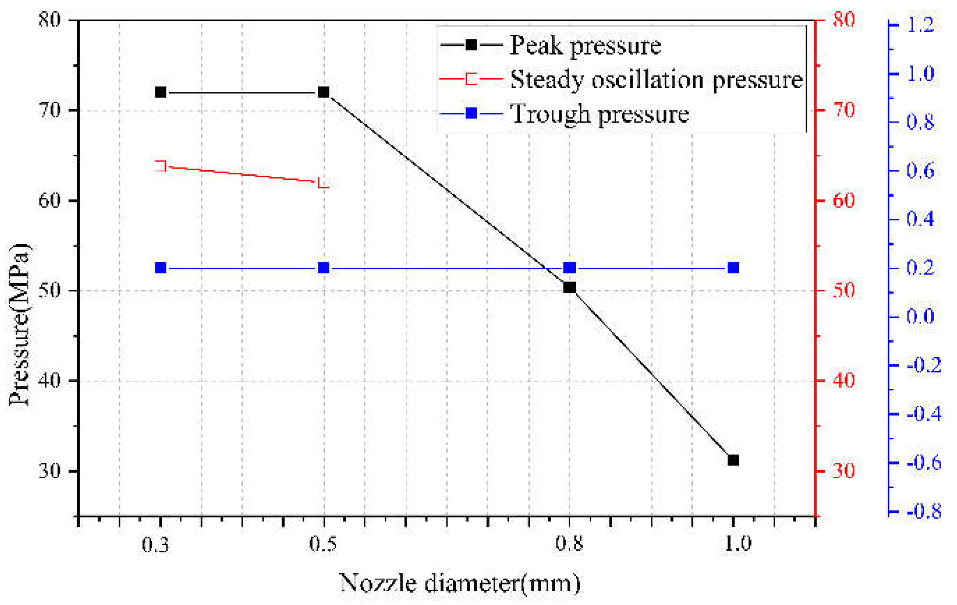
Figure 7, the influence of nozzle outlet diameter on the pressure amplitude during the boosting process can be obtained, as shown in
Figure 9.
①Peak pressure. As the diameter d of the nozzle outlet increases, the peak pressure in the boost chamber gradually decreases. When the movement speed of the piston is fixed, the diameter of the nozzle affects the peak pressure of the boost chamber. As the diameter of the nozzle increases, the peak pressure of the boost chamber gradually decreases. As the diameter of the nozzle increases, the overflow effect of the nozzle cannot be ignored. As the diameter of the nozzle increases, the compression per unit volume continuously decreases, and thus the pressure level gradually decreases.
②Steady oscillation section pressure. As the diameter of the nozzle outlet increases, the steady oscillation pressure gradually decreases, and under current operating conditions, when the nozzle diameter is 0.8 mm or 1.0 mm, the steady oscillation section disappears, that is, there is no steady oscillation pressure. As the diameter of the nozzle increases, the compression per unit volume decreases, and the pressure during the steady oscillation stage decreases accordingly.
③Trough pressure. As the diameter of the nozzle outlet increases, there is no significant change in the trough pressure of the pressurized chamber fluid. The trough pressure of the boost chamber depends on the inlet pressure during the return stage, which is the initial pressure of the boost chamber and is independent of the nozzle diameter.
4.3. The Influence of Nozzle Diameter on Pressure Cycle
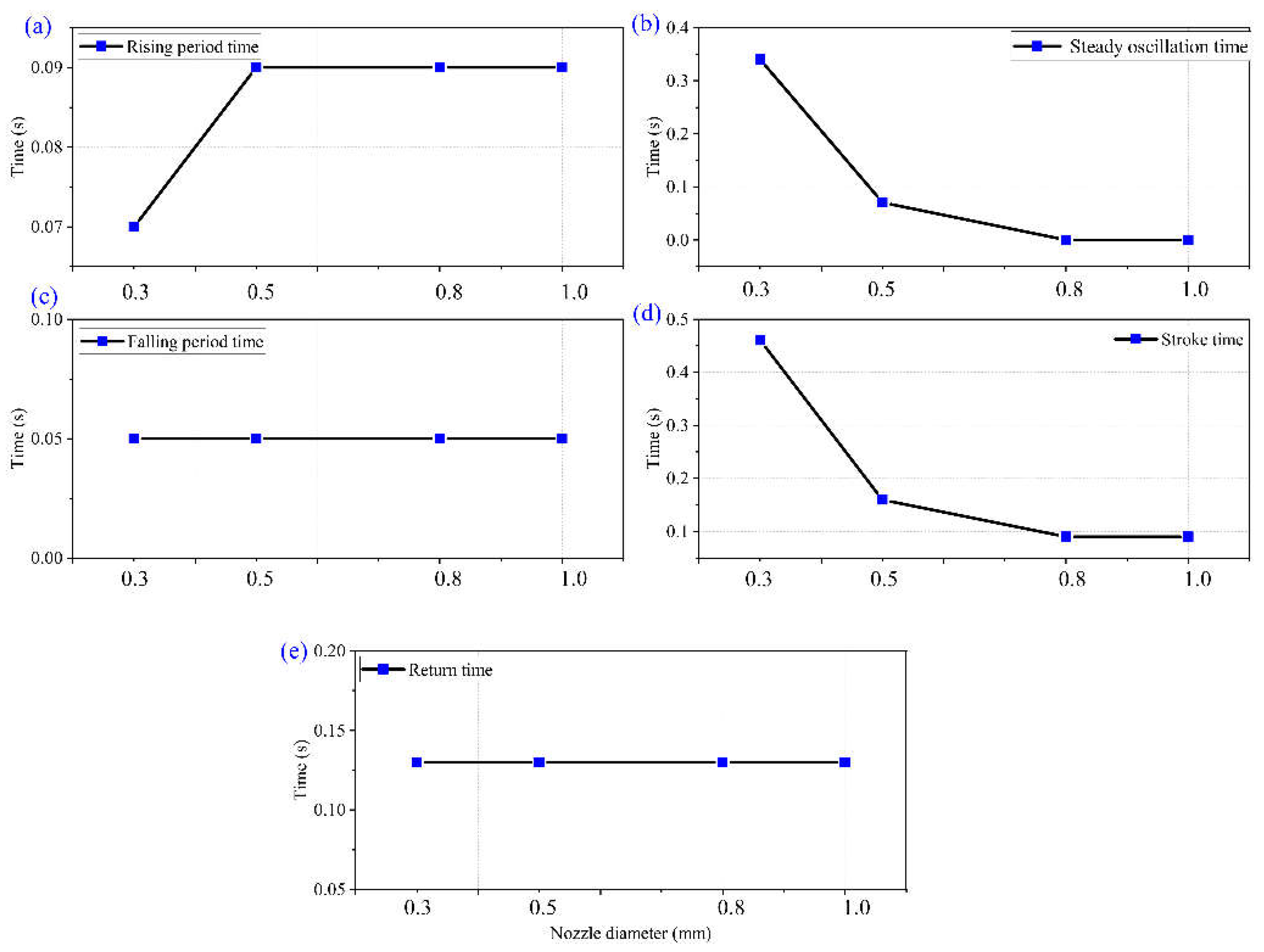
Extracting the fluid pressure cycle of the boosting chamber in
Figure 7, the influence of nozzle outlet diameter on the duration of a single cycle during the boosting process can be obtained, as shown in
Figure 10 and
Figure 11.
① Climb time. As shown in
Figure 10 (a), as the nozzle outlet diameter increases, there is no significant change in the time it takes for the fluid pressure in the booster chamber to climb to the peak pressure. As mentioned above, the climbing time depends on the propagation speed of the water hammer wave, so there is no significant change in the climbing time of the peak pressure.
② The duration of the steady oscillation phase. As the diameter of the nozzle outlet increases, the duration of the steady oscillation section continuously decreases. When the nozzle diameter increases to 0.8 mm and 1.0 mm, the duration of the steady oscillation section decreases to 0 s, meaning that the steady oscillation section disappears. As the nozzle diameter further increases, the overflow effect of the nozzle on the pressurization process cannot be ignored. The movement speed of the squeezing plunger further increases, and the stroke time decreases. On the premise of maintaining the climbing time, the duration of the steady oscillation stage gradually decreases.
③ Fall time. As the diameter of the nozzle outlet increases, there is no significant change in the time required for the descending section.
④ Stroke time. With the increase of nozzle outlet diameter, the time consumed in the stroke stage of extrusion plunger decreases and tends to be flat.
⑤ Return time. With the increase of nozzle outlet diameter, the return time of extrusion plunger has no significant change. In the return stage, the movement of the squeezing piston is mainly completed by the combined action of the driving pressure and the initial pressure of the boosting chamber, independent of the nozzle diameter.
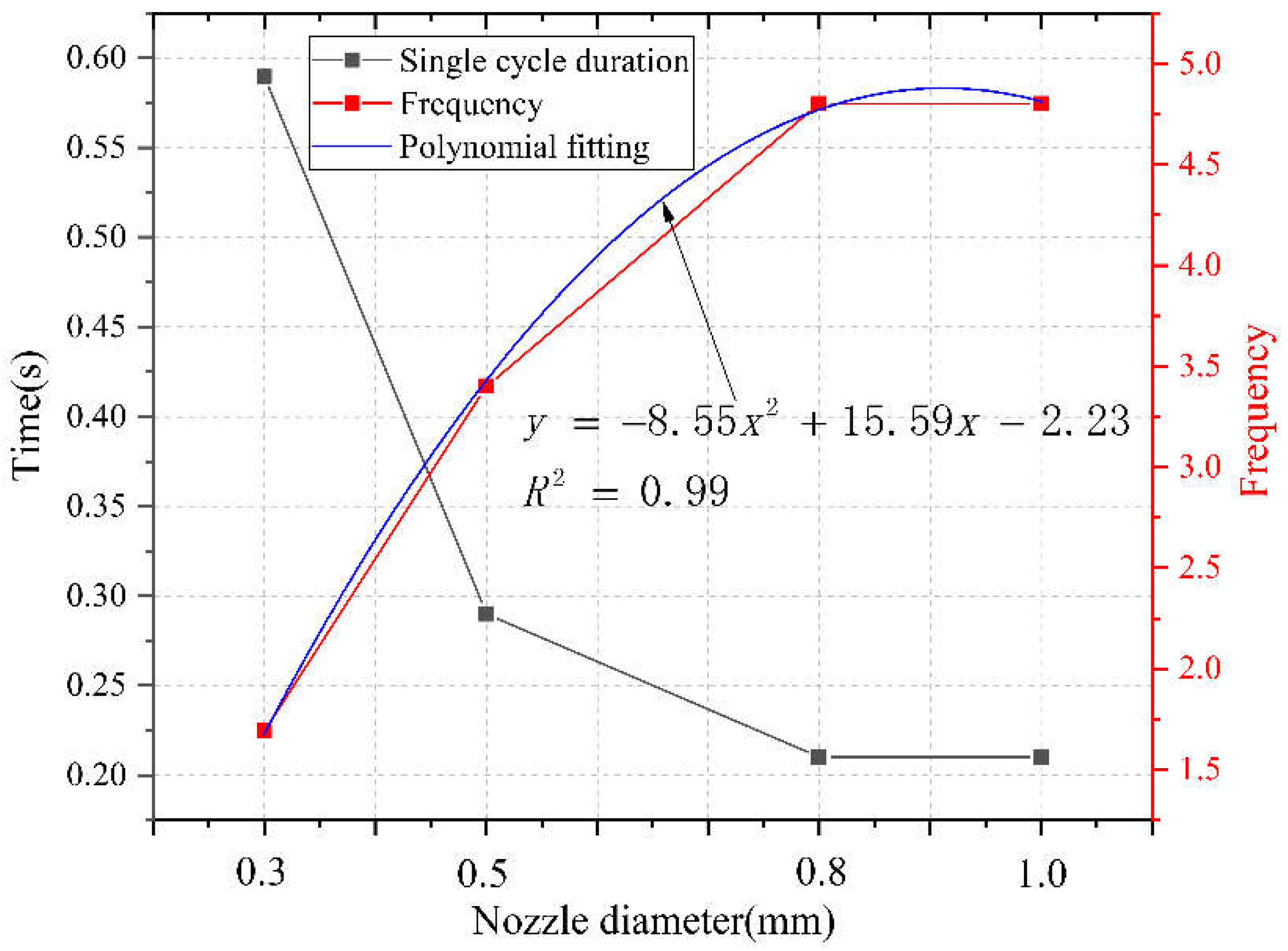
⑥ Duration and frequency of a single cycle. From
Figure 11, it can be seen that as the diameter of the nozzle outlet increases, the duration of a single cycle in the supercharging chamber continuously decreases, the impact frequency continuously increases, and tends to be gentle. The corresponding relationship between the nozzle diameter and the duration of a single cycle under current operating conditions can be obtained through polynomial fitting, as shown in Equation (16):
Based on the analysis results of
Figure 10, it can be seen that when the nozzle diameter increases from 0.3 mm to 1.0 mm, the duration of a single cycle decreases from 0.59 s to 0.21 s. Among them, the stroke stage time decreases from 0.46 s to 0.08 s, accounting for 100% of the single cycle reduction time. That is to say, the increase in nozzle diameter has a full impact on the turbocharging process during the stroke stage, specifically in the steady oscillation stage. Meanwhile, the impact frequency increased from 1.69 to 4.8.
4.4. The Influence of Nozzle Diameter on Boost Ratio
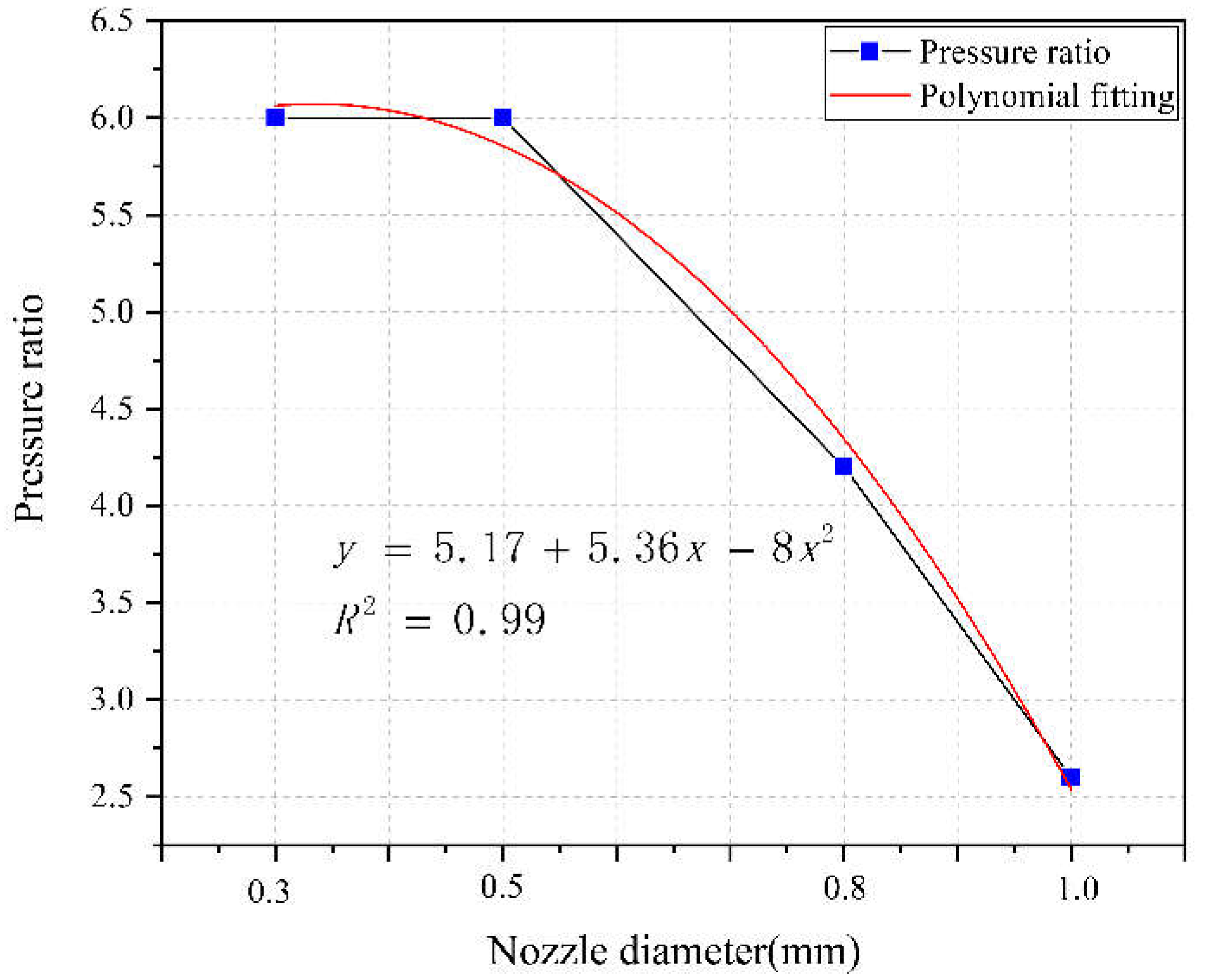
Extracting the fluid pressure cycle of the boost chamber in
Figure 7, the influence of nozzle outlet diameter on the boost ratio during the boost process can be obtained, as shown in
Figure 12.
From
Figure 3.19, it can be seen that as the diameter of the nozzle outlet decreases, the pressurization ratio during the impact stage of the extrusion plunger continues to decrease. By polynomial fitting, the corresponding relationship between the nozzle diameter and the pressurization ratio under current operating conditions can be obtained, which is:
As the diameter of the nozzle increases, the boost ratio between the boost chamber and the driving pressure further decreases. This is because the increase in nozzle diameter increases the flow rate of pressurized fluid overflowing from the nozzle. The actual unit volume compression of fluid by a variable cross-section plunger cannot be directly proportional to the stroke of the variable cross-section plunger. When the driving pressure is 12 MPa and the initial pressure of the boost chamber is 0.2 MPa, the boost ratio gradually decreases as the nozzle diameter increases, and a multiple fitting relationship is shown in equation (17).
Based on the above analysis, it can be concluded that under the same driving pressure and initial pressure conditions, the size of the nozzle diameter determines the pressure pulsation amplitude and pulsation period of the fluid in the pressurized chamber. That is, the nozzle diameter modulates both the amplitude and frequency of the fluid pressure pulsation characteristics. Therefore, the establishment of fluid pressure during the extrusion process requires the adaptation of the corresponding diameter nozzle, which is the critical nozzle diameter. Therefore, the pressurization process of the pressurized pulse water jet generator is dependent on the nozzle.
5. Conclusions
(1) A critical nozzle diameter equation for a pressurized pulse water jet generator has been established. There exists a critical nozzle diameter, and the specific size of the diameter depends on the theoretical boost ratio, inlet oil flow rate, and inlet oil pressure. The inlet oil flow rate is directly proportional to the critical nozzle diameter, the theoretical boost ratio is inversely proportional to the critical nozzle diameter, and the inlet oil pressure is inversely proportional to the critical nozzle diameter.
(2) When the nozzle diameter is greater than the critical diameter, as the nozzle diameter increases, the pressure in the booster chamber tends to change towards a “short and narrow” trend. As the nozzle diameter increases, the peak pressure of the boost chamber decreases, the duration of a single cycle continuously decreases, and the frequency increases.
(3) When the nozzle diameter is less than the critical diameter, as the nozzle diameter increases, the peak pressure in the booster chamber tends to decrease, but the reduction amplitude is weak. The duration of a single cycle gradually decreases and the frequency increases. The nozzle is not involved in the device pressurization process, but provides a load for the establishment of pressurization chamber pressure, which is dependent on the nozzle diameter.
Author Contributions
Conceptualization, Y.Z., S.M.; methodology, Y.Z. and S.M.; validation, Y.Z. and S.M.; formal analysis, Y.Z.; investigation, Y.Z. and S.M.; resources, S.M. and Y.Z.; data curation, Y.Z.; writing—original draft preparation, Y.Z.; writing—review and editing, Y.Z., S.M.; visualization, Y.Z.; supervision, Y.Z.; project administration, Y.Z.; funding acquisition, S.M. All authors have read and agreed to the published version of the manuscript.
Funding
This research was funded by 2023 Wuhu Science and Technology Plan Project (2023yf111), 2024 Anhui Provincial Department of Education College Young and Middle aged Teacher Training Action Project (YQYB2023087), 2024 Henan Province Science and Technology Research Projects (242102220062).
Data Availability Statement
Data presented in this study are available in the article.
Acknowledgments
We are very grateful to Dr. Yuanfei Ling of Chongqing University for his experiment.
Conflicts of Interest
The authors declare no conflict of interest.
References
- LIU Quan-sheng,HUANG Xing ,SHI Kai ,LIU Xue-wei, Utilization of full face roadway boring machine in coal mines deeper than 1 000 km and the key rock mechanics problems, Journal OF China Coal Society,2012,37 (12):2006-2013.
- YUAN Liang, ZHANG Pingsong. Research progress and thinking on integrated tunneling and detection technology of rock roadway with TBM[J]. Coal Geology & Exploration, 2023, 51(1): 21−32.
- ZHANG Ningchuan. Analysis of wear shape of disc-cutter edge of TBM/shield and optimization measures [J]. Tunnel Construction, 2021, 41 (4) : 657.
- Y. Lu, Y. Zhang, J. Tang, Q. Yao, Switching mechanism and optimisation research on a pressure-attitude adaptive adjusting coal seam water jet slotter, International Journal of Mining Science and Technology, 32 (2022) 1167-1179. [CrossRef]
- T. Zhang, X. Wang, J. Hu, J. Ye, Y. Wu, X. Wen, Experimental study on erosion characteristics of salt rock by water jet under low pressure, Journal of Energy Storage, 55 (2022). [CrossRef]
- S. Cao, Z. Ge, Z. Zhou, F. Gao, W. Liu, Y. Lu, Fracturing mechanism and pore size distributions of rock subjected to water jets under in-situ stress: Breakage characteristics investigation, Journal of Petroleum Science and Engineering, 213 (2022). [CrossRef]
- Z.-q. Yang, C. Liu, D.-w. Wang, High-pressure water jet for rock burst prevention of roadway ribs in strong mine pressure mines: a case study, Arabian Journal of Geosciences, 15 (2022). [CrossRef]
- J.-l. Zhang, F.-w. Yang, Z.-g. Cao, Y.-m. Xia, Y.-c. Li, In situ experimental study on TBM excavation with high-pressure water-jet-assisted rock breaking, Journal of Central South University, 29 (2023) 4066-4077. [CrossRef]
- J. Liu, B. Zhu, R. Liu, J. Ling, W. Long, X. Zhang, Study on parameter analysis and damage mechanism of water jet combined with mechanical cutter head breaking concrete, Journal of Building Engineering, 61 (2022). [CrossRef]
- J. Liu, J. Ling, Y. Cai, A. Ju, W. Long, X. Zhang, Study on damage mechanism of concrete under water jet combined with mechanical breaking, Archives of Civil and Mechanical Engineering, 23 (2023). [CrossRef]
- H.-J. Wang, H.-L. Liao, J. Wei, J.-S. Liu, W.-L. Niu, Y.-W. Liu, Z.-C. Guan, H. Sellami, J.-P. Latham, Stress release mechanism of deep bottom hole rock by ultra-high-pressure water jet slotting, Petroleum Science, 20 (2023) 1828-1842. [CrossRef]
- X. Luo, J. Zhang, F. Yang, F. He, Y. Xia, Research on the hard rock cutting characteristics of disc cutter under front-mounted water jet precutting kerf conditions, Engineering Fracture Mechanics, 287 (2023). [CrossRef]
- B. Li, B. Zhang, M. Hu, B. Liu, W. Cao, B. Xu, Full-scale linear cutting tests to study the influence of pre-groove depth on rock-cutting performance by TBM disc cutter, Tunnelling and Underground Space Technology, 122 (2022). [CrossRef]
- Y. Jiang, J. Zeng, C. Xu, F. Xiong, Y. Pan, X. Chen, Z. Lei, Experimental study on TBM cutter penetration damage process of highly abrasive hard rock pre-cut by high-pressure water jet, Bulletin of Engineering Geology and the Environment, 81 (2022). [CrossRef]
- J.-L. Cheng, S.-Q. Yang, W.-F. Han, Z.-R. Zhang, Z.-H. Jiang, J.-F. Lu, Experimental and numerical study on the indentation behavior of TBM disc cutter on hard-rock precutting kerfs by high-pressure abrasive water jet, Archives of Civil and Mechanical Engineering, 22 (2022). [CrossRef]
- X. Liu, S. Liu, H. Ji, Mechanism of rock breaking by pick assisted with water jet of different modes, Journal of Mechanical Science and Technology, 29 (2015) 5359-5368. [CrossRef]
- A.K. Dahiya, B.K. Bhuyan, S. Kumar, Perspective study of abrasive water jet machining of composites — a review, Journal of Mechanical Science and Technology, 36 (2022) 213-224. [CrossRef]
- Z. Ge, Y. Ling, J. Tang, Y. Lu, Y. Zhang, L. Wang, Q. Yao, Formation Principle and Characteristics of Self-Supercharging Pulsed Water Jet, Chinese Journal of Mechanical Engineering, 35 (2022). [CrossRef]
- Y. Zhang, Y. Lu, J. Tang, Y. Ling, L. Wang, Q. Yao, Z. Zhu, Development and application of rock breaking platform with variable cross section extrusion pulsed water jet, Journal of Mechanical Science and Technology, 36 (2022) 2837-2848. [CrossRef]
- Y. Ling, Z. Ge, J. Tang, Y. Lu, Y. Zhang, L. Wang, Development of a hydraulically controlled piston-pressurized pulsed water jet device and its application potential for hard rock breaking, Review of Scientific Instruments, 92 (2021). [CrossRef]
- Y. Zhang, H. Long, J. Tang, Y. Ling, Experimental Investigation on the Granite Erosion Characteristics of a Variable Cross-Section Squeezed Pulsed Water Jet, Applied Sciences, 13 (2023). [CrossRef]
- LU Yiyu, ZHU Zhidan, TANG Jiren, etal. Hard rock-breaking performance of supercharged pulsed waterjet [J].Journal of Vibration and Shock, 2023,42(7):114-122.
- L.-Y. Huang, Z.S. Chen, Effect of technological parameters on hydrodynamic performance of ultra-high-pressure water-jet nozzle, Applied Ocean Research, 129 (2022). [CrossRef]
- D. Li, Y. Kang, X. Ding, X. Wang, W. Liu, Effects of feeding pipe diameter on the performance of a jet-driven Helmholtz oscillator generating pulsed waterjets, Journal of Mechanical Science and Technology, 31 (2017) 1203-1212. [CrossRef]
- Q. Wu, W. Wei, B. Deng, P. Jiang, D. Li, M. Zhang, Z. Fang, Dynamic characteristics of the cavitation clouds of submerged Helmholtz self-sustained oscillation jets from high-speed photography, Journal of Mechanical Science and Technology, 33 (2019) 621-630. [CrossRef]
- M. Juraeva, D.J. Song, D.J. Kang, Computational optimization approach to design a water-jet nozzle for a water-jet loom using the design of experiment method, Journal of Mechanical Science and Technology, 33 (2019) 631-637. [CrossRef]
- Tang jiren, Wang lei, Lu yiyu et al., An experimental study on visualization of pulsation characteristics of supercharged pulsed water jet, Journal of Vibration And Shock,2021,40(20):1-8.
- Zhang yangkai, Lu yiyu, Tang jiren, et al., Experimental study on multi-pulse characteristics of pressurized pulsed water jet , Journal of China University of Mining & Technology,[J/OL],2023.
|
Disclaimer/Publisher’s Note: The statements, opinions and data contained in all publications are solely those of the individual author(s) and contributor(s) and not of MDPI and/or the editor(s). MDPI and/or the editor(s) disclaim responsibility for any injury to people or property resulting from any ideas, methods, instructions or products referred to in the content. |
© 2024 by the authors. Licensee MDPI, Basel, Switzerland. This article is an open access article distributed under the terms and conditions of the Creative Commons Attribution (CC BY) license (http://creativecommons.org/licenses/by/4.0/).
