Preprint
Article

Study on the Equivalent Density Tool and Depressurization Mechanism of Suction-Type Depressurization Cycle

Altmetrics

Downloads

92

Views

18

Comments

0

A peer-reviewed article of this preprint also exists.

Submitted:

08 July 2024

Posted:

08 July 2024

You are already at the latest version

Alerts
Abstract
In order to further control the equivalent circulating density,a new type of annular pres-sure-reducing downhole tool for high temperature and high pressure wells-liquid-absorbing ECD tool is designed.Through this tool,the bottom hole pressure of the equivalent circulating drilling fluid can be close to its hydrostatic pres-sure,therebyachieving a deeper drilling depth.The tool is mainly composed of screw mo-tor,vortex blade,annular seal,universal joint and drill string.Its working principle is mainly to use the liquid absorption effect of the tool and the hydraulic energy of the circu-lating fluid extracted by the screw motor to convert it into mechanical energy,and to gen-erate suction force to improve the flow energy of the drilling fluid in the bottom hole an-nulusand reduce the equivalent circulation density.Based on ANSYS-FLUENT analysis andsimulation,the change of pressure drop characteristics under different drilling fluid density,displacement and tool size was simulated.The simulation results show that thedepressurization effect is 1.0MPa when the drilling fluid density is 1.2g/cm3. When the drilling fluid density is 1.5g/cm3,the depressurization is about 1.7MPa,and when thedrill-ing fluid density is 1.8g/cm3,the depressurization is about 1.9MPa.When the drilling fluid density is 2.0g/cm3,the pressure drop is about 2.3MPa.When the flow rate is from 1500-2500L/min,the maximum pressure can be reduced by 2.3MPa.When the viscosity is 40mPa•S and 60mPa•S,the pressure drop almost does not change.The increase of viscosi-ty has little effect on the pressure drop,and it is mainly affected by the flow rate under equal displacement.
Keywords: 
Subject: Engineering  -   Other

1. Introduction

With the continuous research and improvement of the world is drilling level, the drilling and research technology of deep oil and gas reservoirs has been greatly improved. There are more and more researches on high temperature and high pressure drilling at home and abroad, but most of the research principles and theories of high temperature and high pressure well drilling come from the extension and comparison of land drilling.
In 2008,Zheng Fenghui et al. [1] used the developed jet-type hydraulic depressurization simulation tool and its corresponding test bench to conduct an experimental study on a jet-type hydraulic depressurization method that effectively reduces bottomhole pressure under conventional drilling methods. In 2012, Yuan et al. [2] introduced in detail the structural characteristics, depressurization effect and research and application status of jet pump depressurization tools such as annular jet pump, jet depressurization sub and jet pump bit. In 2013, Zhu et al. [3] proposed a new type of annular jet pump structure based on the principle of jet hydraulic depressurization technology. In 2016,Dokhani Vet al [4] .developed a simulator for calculating wellbore temperature and pressure under cyclic and static conditions, and established a heat transfer mathematical model for offshore inclined well profiles. And verified. In 2016,Erge Oet al. [5] proposed a numerical model to accurately estimate the friction pressure loss in the annulus with and without inner tube rotation. The numerical model was verified by CFD software. In 2019, Abdelgawad et al. [6] developed artificial neural network (ANN)and adaptive neuro-fuzzy inference system (ANFIS).The ANN and ANFIS models were established to calculate ECD. In 2019, Huang Yi et al. [7] derived a risk assessment model based on the prob ability distribution of formation pressure and ECD, using the generalized stress and strength interference reliability theory. The calculation results are consistent with the actual risk in the field. In 2021, Chen Yuwei et al. [8] used the transient cuttings transport model to simulate the transient migration process of cuttings in the wellbore, and combined with the actual drilling data to analyze the influence of cuttings on ECD. In 2021,Huang Wei et al. [9] carried out a study on the calculation method of wellbore ECD in Changning shale gas horizontal well, and explored the calculation method of equivalent static density and equivalent cyclic density of drilling fluid under different temperature and pressure conditions. In 2022, Duan Hongzhi et al [10] carried out high temperature and high pressure density experiments on oil-based drilling fluids commonly used in Xinjiang Oilfield, and established an accurate bottom hole ECD calculation model. In 2022, Foued B [11] et al. proposed a new model to predict ECD in vertical and inclined wells, which predicts cuttings concentration and equivalent cyclic density in vertical and inclined wells. In 2022,Gao Yongde et al. [12] established a wellbore temperature field model for subsea pressurization in order to solve the problem that ECD prediction of deepwater HTHP wells is difficult. In 2022, Wei et al. [13] discussed the check and control technology of high temperature and high pressure wells. Firstly,the development trend was discussed in combination with the current situation, and the key points of ECD check and control technology were summarized. In 2023,in order to improve the calculation accuracy of ECD, Li et al. [14] established a comprehensive calculation model of annular ECD in high temperature and high pressure slim hole horizontal wells by coupling the regression model of drilling fluid density and rheological parameters with the wellbore heat transfer model. In 2023, Okonkwo et al. [15] optimized four error indicators, namely correlation coefficient(R2),mean square error(MSE),root mean square error(RMSE) and mean absolute percentage error(AAPE).The optimized ECD model has high prediction accuracy. In 2023, Mohammed et al. [16] developed two new models ECDeffc.m and MWeffc.m, which improved the calculation accuracy of ECD.
In this paper,a new pressure-reducing tool,the liquid-absorbing ECD-reducing tool,is used to reduce the ECD size in the wellbore.The suction pressure reducing tool is constructed by Solidworks physical model,and the pressure drop characteristics under different parameters are analyzed and simulated based on ANSYS-FLUENT.

2. The Structure of the Suction-Type Falling ECD Tool

2.1. Tool Structure and depressurization Principle

The traditional depressurization method is achieved by reducing the mud density, but in the case of a narrow density window, it may cause complex situations such as well kicks. Therefore, this paper designs a new type of ECD reduction tool-liquid absorption ECD reduction tool. The tool can reduce the equivalent circulation density of the bottom hole without reducing the mud density, and ensure the safety of operation under the narrow density window.
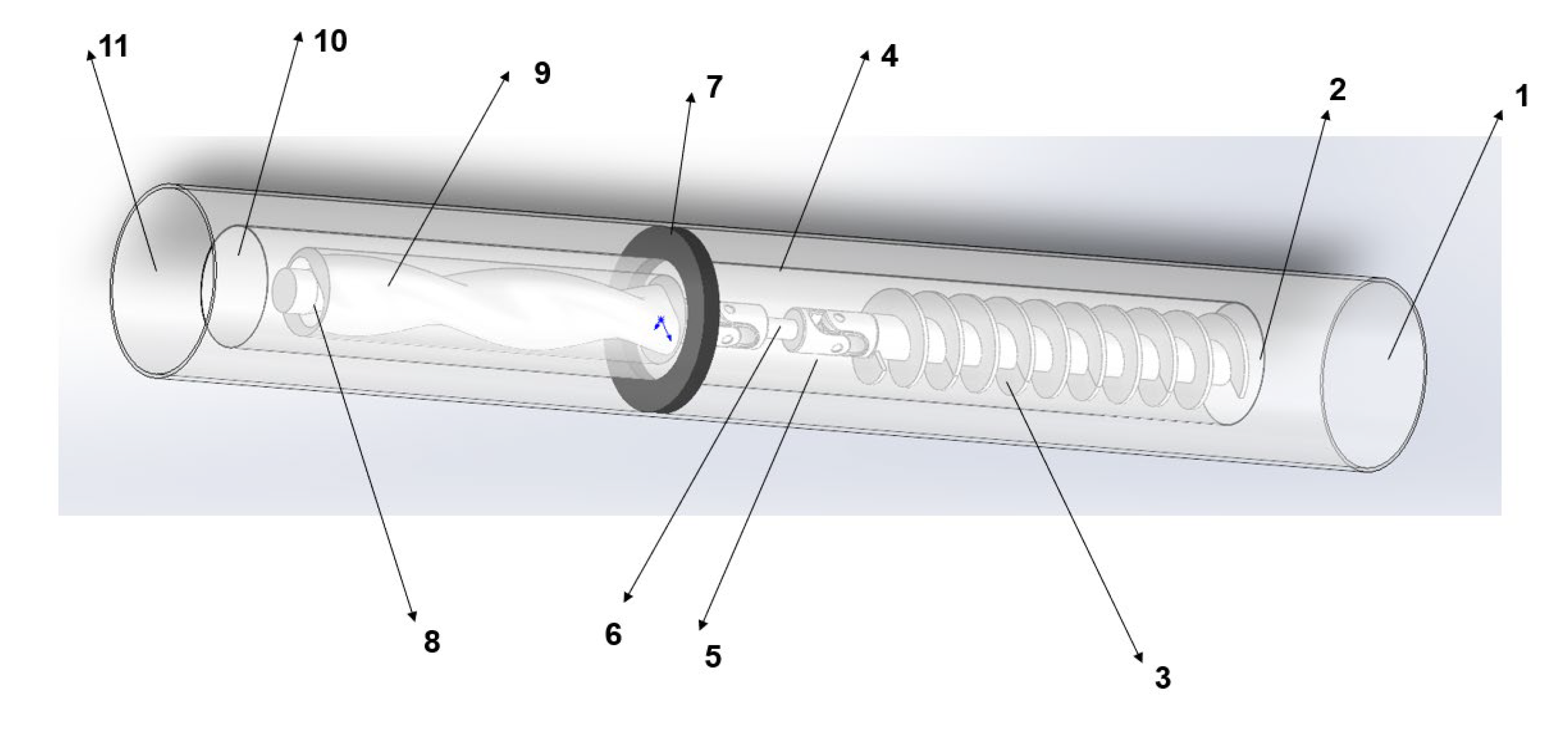
The tool mainly uses the liquid absorption effect, and the hydraulic energy of the circulating fluid is extracted by the screw pump to convert it into mechanical energy, and the suction force is generated to improve the flow energy of the drilling fluid in the bottom hole annulus and reduce the equivalent circulation density. The tool is mainly composed of screw motor, spiral blade, annular seal and drill string. Figure 1 (a,b,c,d) Its tool parts.
The top of the tool is a screw motor, which can convert the hydraulic energy generated by the circulating fluid and convert the hydraulic energy into mechanical energy. Then the screw drives the spiral blade to rotate. The backflow fluid replenishes energy and generates the required pressure difference in the annulus. In general, the screw pump is matched with the blade; therefore, there is no need to adjust the speed. The lower section of the liquid-absorbing ECD-reducing tool is composed of an annular seal to ensure that all flowback fluid and cuttings pass through the pump. The annular seal is always in contact with the casing and supported on the bearing, so that the annular seal does not rotate relative to the casing when the drill string rotates.

2.2. Parameters of Tools

Field applications have been carried out abroad, and there are few domestic applications. In addition, field applications have shown that there are significant differences in the magnitude of pressure reduction under different drilling parameters.
The liquid-absorbing ECD reduction tool is a self-activating tool powered by a circulating drilling fluid. When the drilling fluid is circulating, it starts automatically, and when the cycle stops, it stops running. The tool is used to process drilling fluids with a density of up to1.8g/cm3.The current prototype has an outer diameter of 208.3mm, an inner diameter of 46mm, a casing size of 244.5mm-339.7mm, a length of about 9.15m, a top and bottom connection length of 114.3cm, and a maximum fluid circulation speed of 2.27L/min. The tool can handle a circulation rate of up to 2.27L/min.

3. Numerical Simulation

In this paper, the pressure drop effect of the liquid-suction ECD reduction tool under different conditions is analyzed by numerical simulation. The liquid-absorbing ECD reduction tool is constructed by Solidworks physical model, and the pressure drop characteristics under different parameters are analyzed and simulated based on ANSYS-FLUENT.

3.1. The Simulation Pretreatment of the Liquid-Suction ECD reduction Tool Model

3.1.1. Computation Module

The equivalent circulating density(ECD)of drilling fluid can be defined as the sum of the equivalent static density of drilling fluid and the annulus pressure drop caused by drilling fluid flow. The expression of the equivalent cyclic density in the field case is shown in(1) [17] :
ρ ecd = ρ esd + Δ P 0 . 052 h
In the formula: ρ ecd is the cyclic equivalent density; ρ esd is the equivalent static density; Δ P is frictional pressure drop.
High temperature and high pressure drilling is closely related to the control of downhole pressure. The density and rheology of drilling fluid are the key problems. The equivalent density of drilling fluid equivalent circulation loop is an important parameter to control the bottom hole pressure. The ECD expression of the equivalent cyclic
density in the field case is shown in (2):
ECD = ρ 1 - C a + ρ s C a + Δ p 0.00981 H
In the formula: ρ is the drilling fluid density; ρ s is the density of rock debris; C a is the concentration of annular cuttings; Δ p is the annular pressure loss;
The calculation formula of the annulus concentration of the annulus concentration calculation model (3):
C a = v a 3600 v c - v s 1 - d 0 2 d 2
In the formula : v a is the drilling speed ; d 0 Is the outer diameter of the drill pipe ; d is the inner diameter of the wellbore ; v c It is the annular return velocity of drilling fluid ; v s It is the settling velocity of rock debris.
The annular pressure loss calculation model, when the flow pattern is turbulent, the calculation formula of the pressure loss of the annular section is as follows (4) :
Δ P = 2 . 04 f ρ v c 2 l d - d 0
In the formula : Δ P is the annular pressure loss ; l is the length of drill pipe; d 0 Is the outer diameter of the drill string ; d is the inner diameter of the wellbore ; v c is the annular return velocity of drilling fluid ; f is the friction coefficient, dimensionless ; ρ Is the density of drilling fluid.

3.1.2. Meshing and Boundary Condition Setting

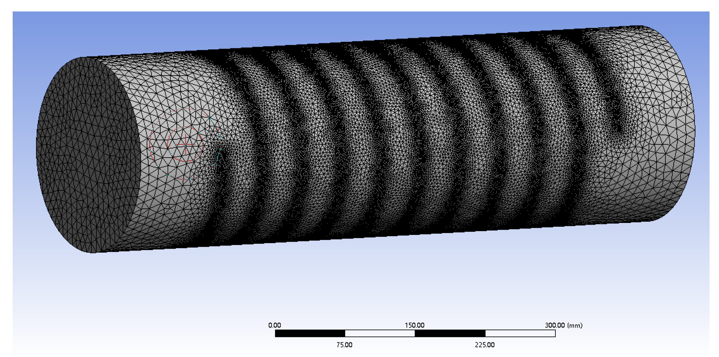
Based on the Solidworks modeling tool, the physical model of the suction-type falling ECD tool is constructed. The finite element analysis model of the tool is established by meshing the model through Meshing. In order to ensure a certain calculation accuracy and not to cause too long calculation time due to excessive calculation, a more detailed meshing of the key parts (blades) that are prone to fatigue damage is performed to improve the calculation accuracy, as shown in Figure 3.
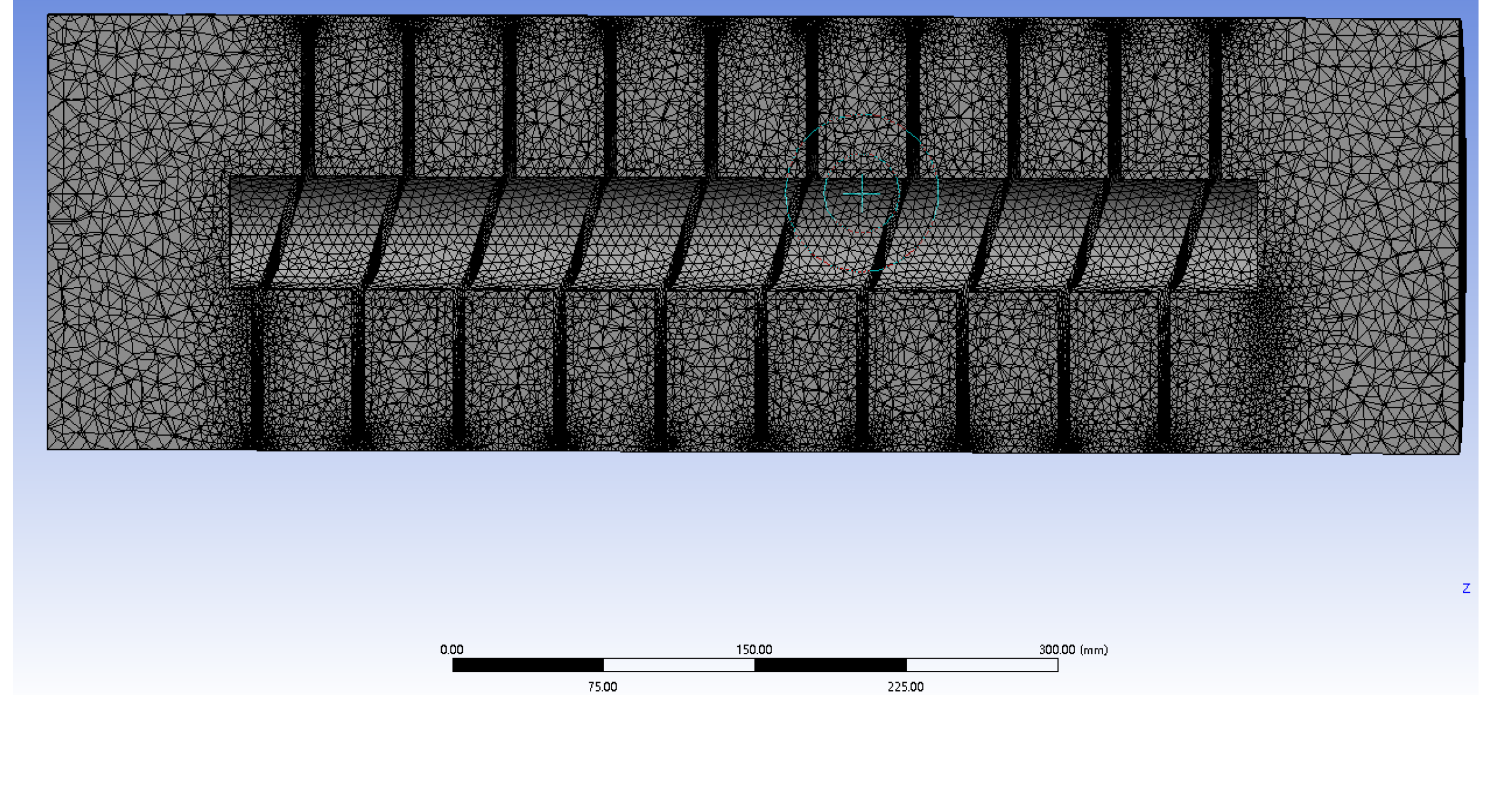
Relatively rough meshing is performed on other parts with simple and stable structures to improve computational efficiency, as shown in Figure 4
Based on ANSYS-FLUENT, the boundary condition parameters of the tool are set as well depth 4275m, drilling fluid displacement 1500L/min-2500L/min, drilling fluid density1.2-2.8g/cm3, inner diameter 9-5/8'in(244.5mm), wellbore diameter 190.5mm, tripping speed 0.25m/s, drilling fluid viscosity 20-60mPa•S.

3.2. The Pressure Drop Distribution of the Liquid-Absorbing ECD-Reducing Tool when Drilling Fluid Flows with Different Densities
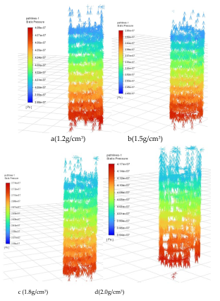
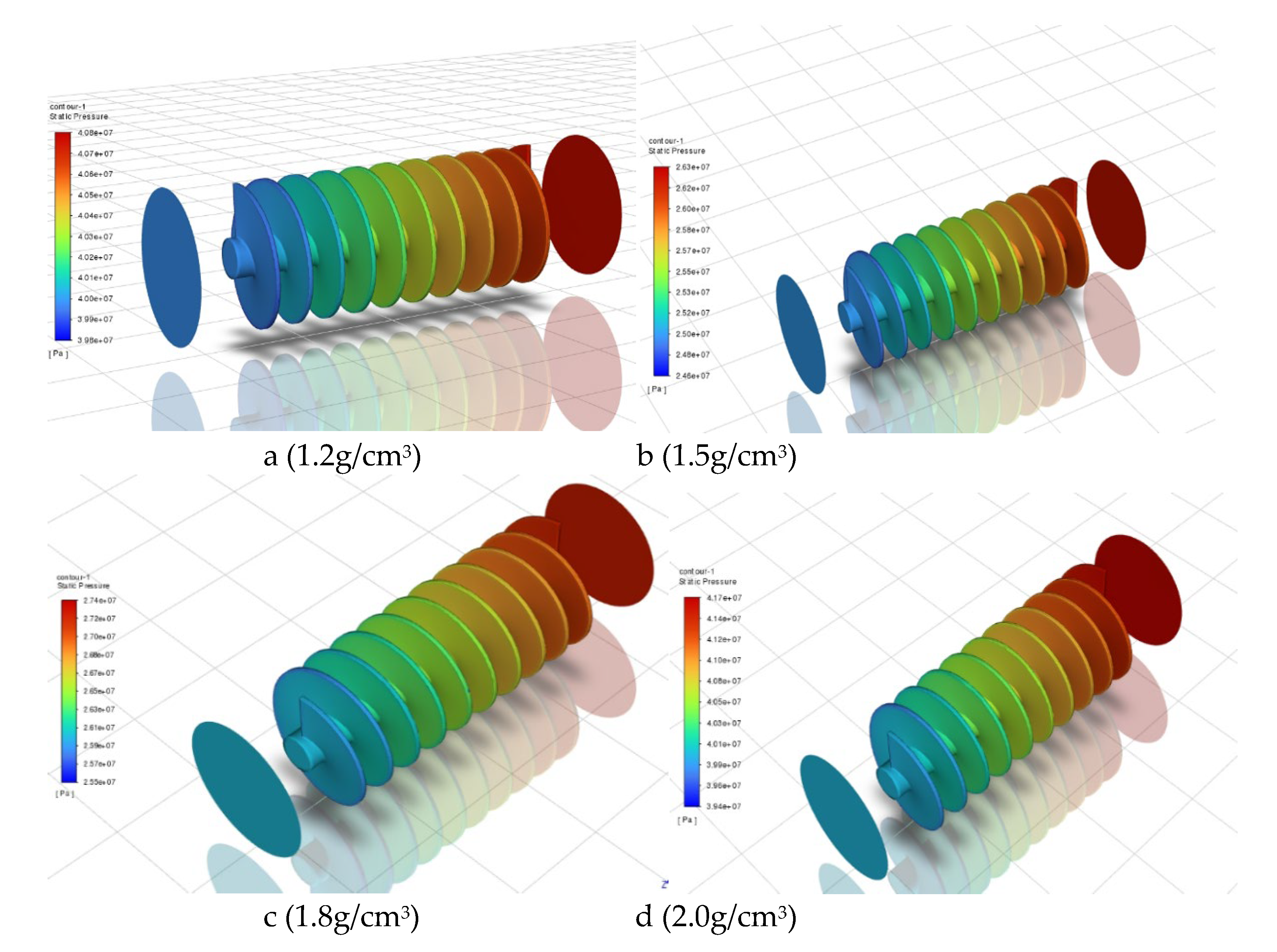
Based on ANSYS-FLUENT, the pressure drop distribution characteristics of drilling fluid density (1.2g/cm3,1.5g/cm3,1.8g/cm3,2.0g/cm3) flowing through the liquid-absorbing ECD tool under different parameters are simulated (Figure 6). Among them a,b,c and d are the pressure drop distribution characteristics of drilling fluid density:1.2g/cm3,1.5g/cm3,1.8g/cm3,2.0g/cm3.
By analyzing Figure 6, when the drilling fluid density is 1.2g/cm3, the depressurization effect is only 1MPa.The depressurization effect is not obvious. When the drilling fluid density is 1.5g/cm3,the depressurization is about 1.7MPa.When the drilling fluid density is 1.8g/cm3,the depressurization is about 1.9MPa.When the drilling fluid density is 2.0g/cm3,the depressurization is about 2.3MPa.From the simulation results, it can be obtained that with the increase of drilling fluid density, the pressure drop value will fluctuate obviously, and the pressure drop effect is more obvious. However, the density of drilling fluid should also be reasonably controlled. Too high density will make the pressure in the wellbore too large, resulting in increased risk of tool seal failure.
Figure 7 simulates the flow distribution characteristics of three different density fluids. It can be seen more intuitively that the pressure drop distribution characteristics and flow direction of the fluid. It can be seen from the fluid flow distribution that there are obvious pressure drop distributions under different density conditions, but the greater the density, the more obvious the pressure drop effect.
Preprints 111540 i001

3.3. The Pressure Drop Distribution of the Liquid Absorption ECD Tool at Different Displacement

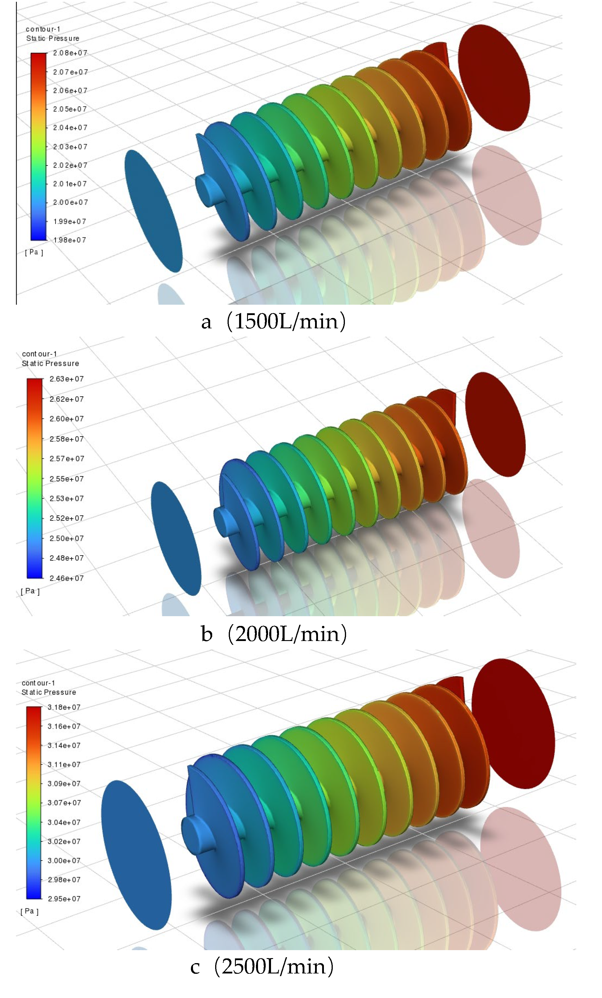
Based on ANSYS-FLUENT, the pressure drop distribution characteristics of three different parameters (1500L/min,2000L/min,2500L/min) flowing through the liquid-suction ECD tool were simulated (Figure 8). The flow rates of a, b and c are: 1500L/min, 2000L/min, 2500L/min.
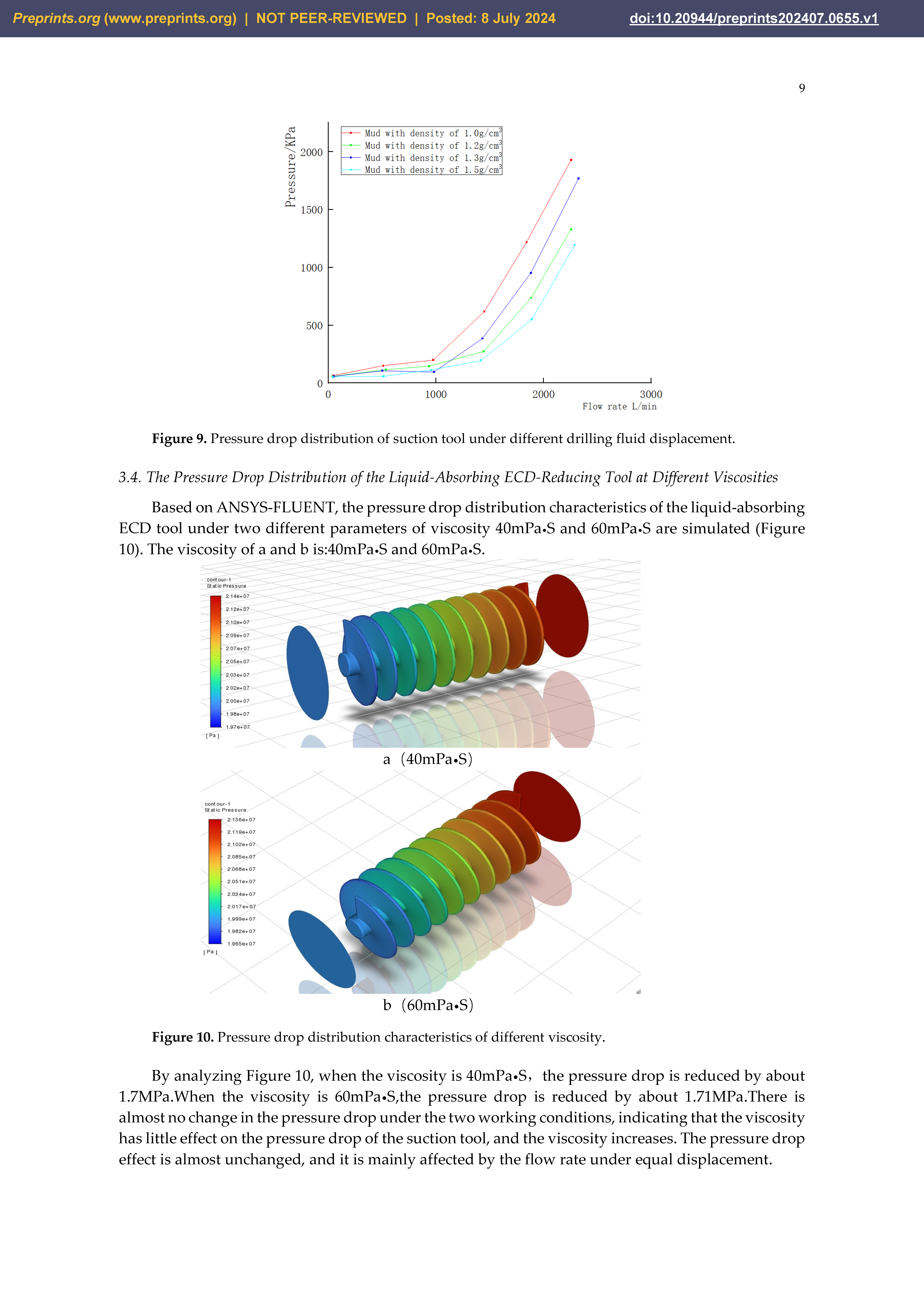
By analyzing Figure 7,when the drilling fluid displacement is 1500L/min, the pressure is reduced by 1.1MPa ; when the drilling fluid displacement is 2000L/min, the pressure is reduced by about 1.7MPa;when the drilling fluid displacement is 2500L/min, the pressure is reduced by about 2.3MPa.It can be seen that with the increase of drilling fluid displacement, the pressure drop value will fluctuate obviously, and the pressure drop effect is more obvious. With the increase of drilling fluid displacement, the depressurization effect will be improved, and the depressurization effect and diversion effect of the tool are not obvious when the displacement is small.Figure 9shows the pressure drop distribution of the liquid-absorbing tool under different drilling fluid displacement. The simulation results show that the liquid-absorbing pressure drop tool has a more obvious effect on local pressure reduction.

3.4. The Pressure Drop Distribution of the Liquid-Absorbing ECD-Reducing Tool at Different Viscosities

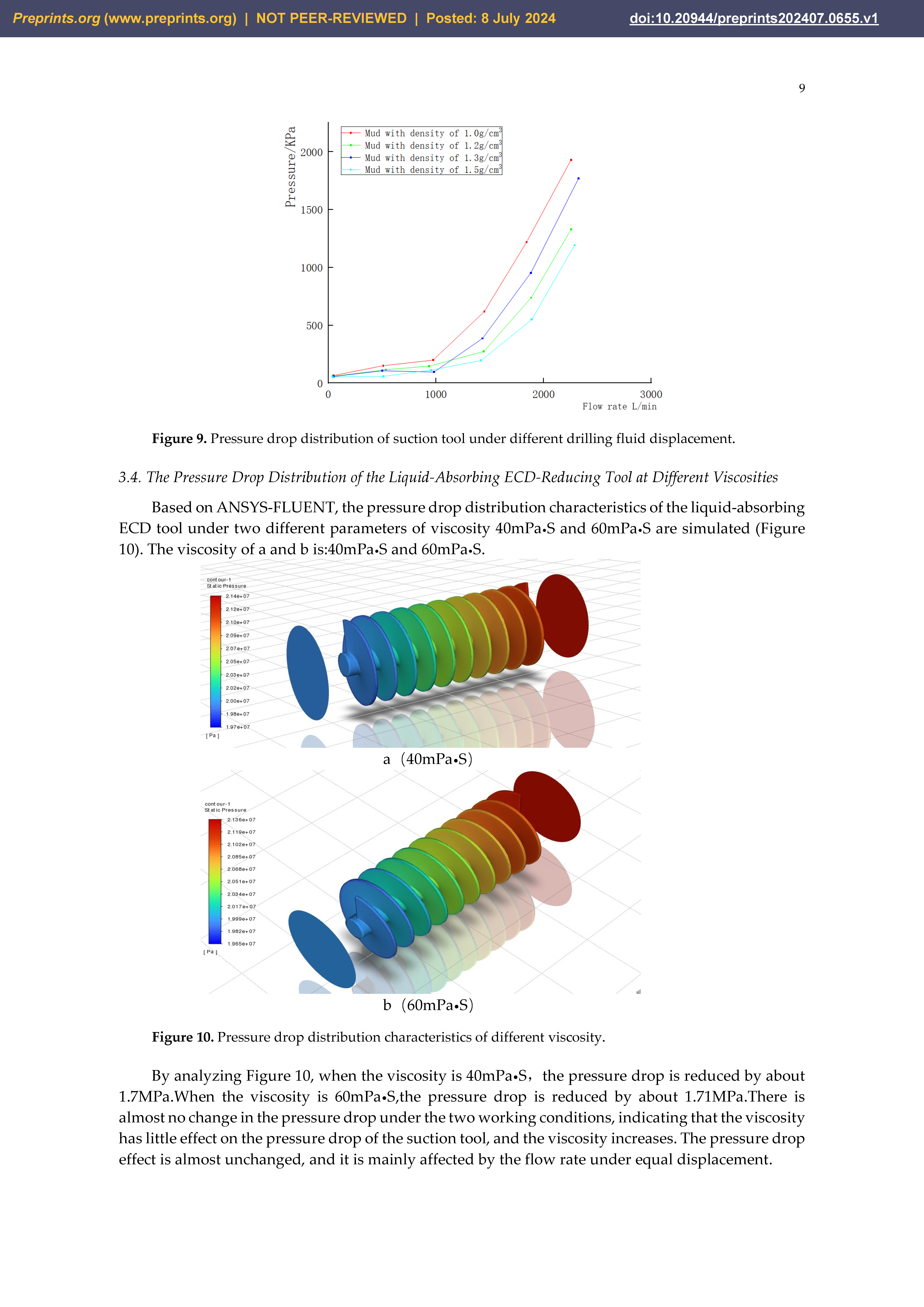
Based on ANSYS-FLUENT, the pressure drop distribution characteristics of the liquid-absorbing ECD tool under two different parameters of viscosity 40mPa•S and 60mPa•S are simulated (Figure 10). The viscosity of a and b is:40mPa•S and 60mPa•S.
By analyzing Figure 10, when the viscosity is 40mPa•S,the pressure drop is reduced by about 1.7MPa.When the viscosity is 60mPa•S,the pressure drop is reduced by about 1.71MPa.There is almost no change in the pressure drop under the two working conditions, indicating that the viscosity has little effect on the pressure drop of the suction tool, and the viscosity increases. The pressure drop effect is almost unchanged, and it is mainly affected by the flow rate under equal displacement.

4. Field test

According to the wellhead injection temperature and pressure are known, as a boundary condition, the data in this paper is based on the field data of Cao 8well in Jiangsu Caoshe Oilfield [17] , and tested in its field in the second half of 2023.Among them, the deepest measured well depth reaches 2600m,the drill bit adopts 6-1/2'in(165.1mm)PDC bit, the drilling fluid displacement is 1500L/min-2000L/min, the outer diameter of the casing is 9-5/8'min(244.5mm), the length of the drill pipe section is 10m,the wellbore diameter is 260.5mm, the tripping speed is 0.25m/s, the viscosity of the drilling fluid is 40mPa•S, the friction coefficient is 0.029, the surface temperature is 288.15K, and the geothermal gradient is 0.03K/m.
The inner diameter of the test tool is 7-1/2'in(190.5mm), the outer diameter is 9-5/8'in(244.5mm), the drilling fluid density is 1.5g/cm3, and the tool is installed at a distance of 800m from the wellhead. After field testing, the pressure reduction effect of the tool can be about 2MPa, reaching its target pressure reduction value. Table 4 contains the pressure change table of the depressurization tool.
It can be seen from Figure 11that the pressure value has obvious fluctuation in the case of containing depressurization tools in the wellbore, and the pressure is reduced by about 1.7 MPa, which meets the requirements of on-site depressurization.

5. Conclusion

Based on ANSYS-FLUENT to simulate the pressure drop characteristics under different parameters, we can get the following conclusions.
(1) The traditional solution has been difficult to solve the problem of efficient and rapid drilling of complex wells such as narrow density window. It must be fundamentally improved, relying on the change of equipment and drilling methods to solve the complex situation in the drilling process.
(2) With the increase of drilling fluid density (1.2-2.0g/cm3), the depressurization effect increases gradually, and the pressure drop effect is more obvious, and the depressurization value is up to 2.3MPa; however, the density of drilling fluid should also be reasonably controlled. Too high density will make the pressure in the wellbore too large, resulting in increased risk of tool seal failure.
(3) With the increase of drilling fluid displacement(1500-2500L/min), the pressure drop value will fluctuate obviously, and the pressure drop effect is more obvious, up to about 2MPa.With the increase of drilling fluid displacement, the depressurization effect will be improved, and the depressurization effect and diversion effect of the tool are not obvious when the displacement is small.
(4) When the viscosity is 40mPa•S, the pressure drop is about 1.7MPa, and when the viscosity is 60mPa•S, the pressure drop is about 1.71MPa. There is almost no change in the pressure drop under the two working conditions. The viscosity has little effect on the pressure drop of the suction tool, and it is mainly affected by the flow rate under equal displacement.

Author Contributions

Ren Meipeng put forward innovative ideas and grasped the research direction.; Zhang Xingquan is responsible for the analysis of step-down algorithm; Xie Renjun is responsible for the software simulation of the step-down tool; Wang Junyan is responsible for the construction of the physical model of the step-down tool; Zhu Zhaopeng is responsible for the physical construction of depressurization tools; Cheng Xuebin is responsible for the test site of depressurization tools; Dou Liangbin provides financial assistance.

Funding

This study was funded by Dou Liangbin, funded projects : Shaanxi Province key research and development plan ; project number:2024GX-YBXM-503

Data Availability Statement

As the project is in the development stage, the data is temporarily confidential.

Acknowledgments

In this section, you can acknowledge any support given which is not covered by the author contribution or funding sections. This may include administrative and technical support, or donations in kind (e.g., materials used for experiments).

Conflicts of Interest

The funders had no role in the design of the study; in the collection, analyses, or interpretation of data; in the writing of the manuscript; or in the decision to publish the results”.

References

  1. Zheng Fenghui,Yu Shuijie,Li Gensheng,etc.Jet hydraulic depressurization experimental study [J].Petroleum Machinery,2008(07):4-6+22+88.
  2. Yuan Guangyu.Research Status and Performance Analysis of Jet Pump Tool for Reducing Bottom Hole Pressure Difference [J].Oil Drilling Technology,2012,40(04):76-80.
  3. Zhu Haiyan,Deng Jingen,He Yufa,etc.Hydraulic jet technology to reduce bottom hole pressure difference [ J ].Journal of China University of Petroleum ( Natural Science Edition ),2013,37 ( 02 ) : 50-56.
  4. Dokhani V,MaY,Yu M.Determination of equivalent circulating density of drilling fluids in deepwater drilling [J].Journal of Natural Gas Science and Engineering,2016,341096-1105.
  5. Erge O,Ozbayoglu M E,Miska Z S,et al.Equivalent circulating density modeling of Yield Power Law fluids validated with CFD approach [J].Journal of Petroleum Science and Engineering,2016,140 16-27.
  6. Abdelgawad Z K,Elzenary M,Elkatatny S,et al.New approach to evaluate the equivalent circulating density (ECD) using artificial intelligence techniques [J].Journal of Petroleum Exploration and Production Technology,2019,9 (2):1569-1578.
  7. Huang, Yi; et al. Quantitative risk assessment method for high temperature and high pressure drilling engineering in Yingqiong Basin [J].Offshore Oil and Gas of China,2019,31(4):119-124.
  8. Chen Yuwei and so, on. Extended reach well hole cleaning and ECD control [J].China Science and Technology Paper,2021,16(09):1017-1022.
  9. Huang Wei.Study on ECD calculation method of Changning shale gas horizontal well [D].China University of Petroleum (Beijing),2021.
  10. Duan Hongzhi.Study on the calculation method of high temperature and high pressure ECD of oil-based drilling fluid in Xinjiang Oilfield [D].China University of Petroleum (Beijing),2022.
  11. Foued B,Vamegh R,Nidhal B.Impact of hole cleaning and drilling performanceon the equivalent circulating density [J].Journal of Petroleum Science and Engineering,2022,211.
  12. Gao, Yongde; et al. Prediction model and application of drilling fluid equivalent circulation density in deepwater HTHP wells [J].Special oil and gas reservoirs,2022,29 (03):38-143.
  13. Wei Xiaoqi.Key points of ECD check and control technology for high temperature and high pressure wells [J].Chemical management,2022(18):157-160.
  14. Li, Wentuo; et al. Annular ECD comprehensive calculation model of high temperature and high pressure slim hole horizontal well [J] Petroleum drilling and production technology,2023,45(03):259-268.
  15. Okonkwo F I S,Joel F O.Modelling the Effects of Temperature and Pressure on Equivalent Circulating Density (ECD) During Drilling Operations Using Artificial Neural Networks [J].Journal of Engineering Research and Reports,2023,25 (9): 70-82.
  16. Mohammed A ,Mohammed A ,Bayan A ,et al.A Developed Robust Model and Artificial Intelligence Techniques to Predict Drilling Fluid Density and Equivalent Circulation Density in Real Time.[J].Sensors (Basel,Switzerland),2023,23 (14):. [CrossRef]
  17. Liang, Xu; et al. Density calculation model and influence analysis of high temperature and high pressure oil-based drilling fluid [J].Petrochemical application,2023,42(03):64-69.
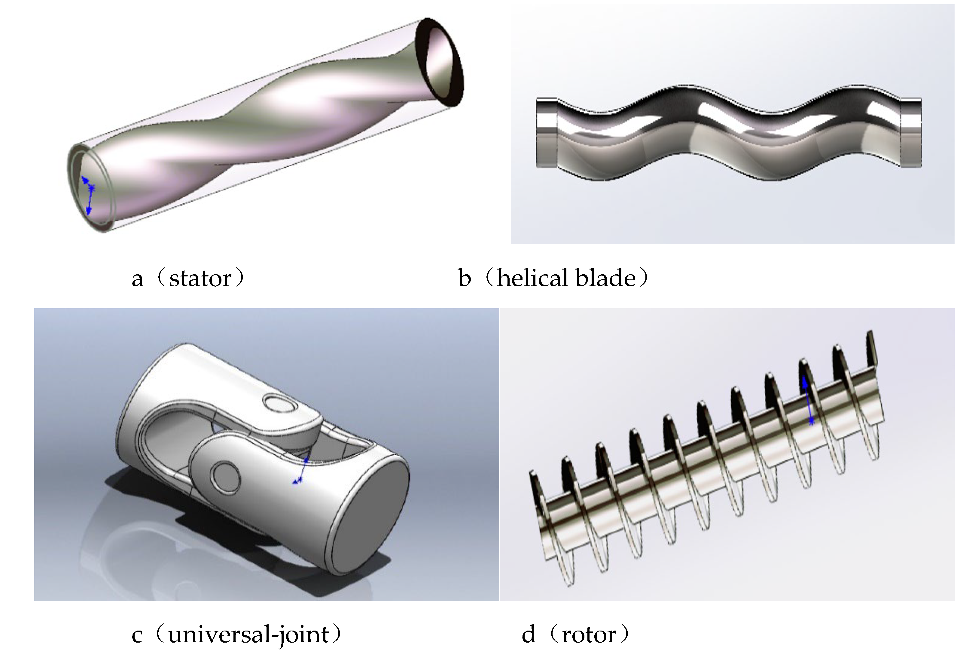
Figure 1. Structure diagram of parts of liquid-suction ECD reduction tool.
Preprints 111540 g001
Figure 2. The overall structure of the liquid-absorbing ECD reduction tool. 1:Shaft inlet;2:Import of depressurization tools;3:Rotating blades;4:Tool jacket;5:Universal axis;6:Prevent the assembly;7:Sealing ring;8:Screw rotor;9:Screw stator;10:Tool export;11:Shaft outlet;
Preprints 111540 g002
Figure 3. Grid division.
Preprints 111540 g003
Figure 4. Tool grid partition section diagram.
Preprints 111540 g004
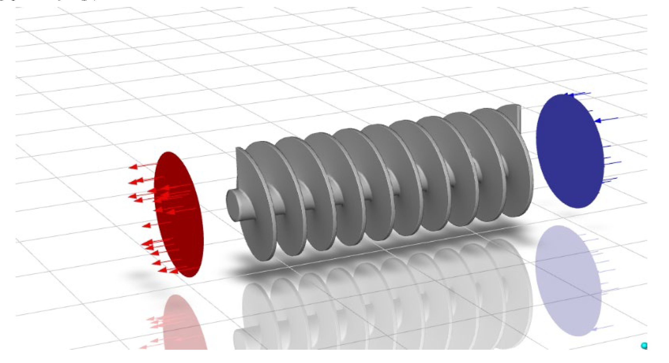
Figure 5. Tool simulation flow direction.
Preprints 111540 g005
Figure 6. Pressure drops distribution of different drilling fluid density.
Preprints 111540 g006
Figure 8. Pressure drop distribution characteristics and fluid flow distribution characteristics at different displacement.
Preprints 111540 g007
Figure 9. Pressure drop distribution of suction tool under different drilling fluid displacement.
Preprints 111540 g008
Figure 10. Pressure drop distribution characteristics of different viscosity.
Preprints 111540 g009
Figure 11. Wellbore pressure with depressurization tool.
Preprints 111540 g010
Table 1. includes pressure change table of depressurization tool.
Well Depth/m Normal Drilling Pressure/MPa Contains Pressure Relief Tool Pressure/MPa Depressurization Value /MPa
800 11.76 10.08 1.68
1000 14.70 12.96 1.74
1200 17.64 15.98 1.66
1400 20.58 18.81 1.77
1600 23.52 21.70 1.82
1800 26.46 24.87 1.59
2000 29.40 27.48 1.92
2200 32.34 30.32 2.02
2400 35.28 33.39 1.89
2600 38.22 36.23 1.99
Disclaimer/Publisher’s Note: The statements, opinions and data contained in all publications are solely those of the individual author(s) and contributor(s) and not of MDPI and/or the editor(s). MDPI and/or the editor(s) disclaim responsibility for any injury to people or property resulting from any ideas, methods, instructions or products referred to in the content.
Copyright: This open access article is published under a Creative Commons CC BY 4.0 license, which permit the free download, distribution, and reuse, provided that the author and preprint are cited in any reuse.
Prerpints.org logo

Preprints.org is a free preprint server supported by MDPI in Basel, Switzerland.

Subscribe

© 2024 MDPI (Basel, Switzerland) unless otherwise stated