1. Introduction
Diesel engines, known for their efficiency and durability, are widely used in transportation and industrial applications, such as automobiles, marines, fishing boats, power generators, mines and others. They are useful for reducing CO
2 emissions due to their high thermal efficiency and omnivorousness of consumption of different kinds of fuel, including biofuels [
1,
2,
3].
However, the emissions generated by these engines pose significant environmental and health concerns. One of the most critical components of diesel exhaust is particulate matter suspended in gas phase, which is the result of an incomplete combustion of fuels. Diesel exhaust particulates (DEPs) constitute the aggregates of primary particles with various compounds adsorbed on their surface. Diesel emission particulates mostly consist of dry soot (carbon, C), condensed organic or inorganic substances, a soluble organic fraction (SOF), hydrocarbon compounds (HCs), nitrates, and sulfates [
4].
Diesel exhaust particulate matter is notoriously harmful when inhaled due to its minuscule size, since the diameter of the aggregates is in the range 10 nm to 10000 nm. It allows it to penetrate deep into the lungs and even enter the bloodstream. This capability is associated with significant respiratory and cardiovascular issues [
5]. Furthermore, DEPs have been classified as a Group 1 carcinogen by the International Agency for Research on Cancer, solidifying its reputation as a severe public health hazard [
6]. Studies have demonstrated that long-term exposure to diesel exhaust can lead to chronic respiratory conditions, reduced lung function, and an increased risk of heart diseases [
7]. Moskal and Penconek, in their previous study, provided critical insights into how these particles deposit in the human respiratory tract. Their research emphasizes that the size and composition of diesel exhaust particles vary with fuel type and combustion conditions, influencing the deposition efficiency and pattern within the respiratory system [
8]. The adverse health effects associated with diesel exhaust particulates have been extensively studied, demonstrating a clear link to respiratory diseases, cardiovascular conditions, and even cancer. Therefore, its reduction has gained international interest.
In recent years, the focus has shifted towards innovative methods for mitigating these emissions. Air cleaners that incorporate high-efficiency particulate air (HEPA) filters and electrostatic precipitators are successful for decreasing the concentration of suspended particulate matter in the atmosphere. For DEPs in the exhaust gas of diesel engines, a diesel particulate filter (DPF) is installed in the exhaust pipe and their efficiency usually reaches 95% or more. Nevertheless, one must take under consideration the relatively large pressure loss associated with HEPA and DPF [
9].
Among the emerging technologies, in-flight methods, including low-temperature (non-thermal) plasma, LTP, reactors have shown considerable promise. These reactors operate by ionizing the air at atmospheric pressure, producing reactive species capable of breaking down pollutants at relatively low temperatures [
10,
11]. This method is particularly attractive for its efficiency, scalability, and potential for integration with existing exhaust systems in diesel engines.
The gliding arc (GA) discharge is particularly effective due to its ability to generate high concentrations of reactive species in relatively big area while maintaining a relatively low gas temperature. This low-temperature operation is beneficial for preventing the formation of secondary pollutants and reducing the thermal stress on engine components. The gliding arc system’s design also facilitates seamless integration into existing exhaust mechanisms, thereby allowing for its application in various industrial and vehicular settings. Several studies have documented the effectiveness of LTP (low temperature plasma) reactors in decomposing NO
x, SO
x, and hydrocarbons present in exhaust gases. However, specific attention to the application of these reactors for particulate matter control is still emerging. For example, Chae presented the review of application of non-thermal plasma technique to treat diesel exhaust [
12]. Thomas et al. noted the effect of residence time on the oxidation of soot particles (particulate matter), but in packed dielectric barrier discharge (DBD) reactors [
13]. Pan et al. showed a great oxidative potential of LTP (obtained in DBD reactors) in decreasing the concentration of the carbon particles from diesel engine exhaust, which resulted in an effective conversion of carbon particles to CO and CO
2, while series of complex chemical reactions with carbon particles lead to reducing the diameter of particles, as well as the number of C atoms [
14]. Yamasaki et al. proposed an in-flight DBD plasma system that can provide a large filtering volume, improve the residence time characteristics of radicals, and increase the decomposition performance of the system [
9]. They examined the particulates removal reactions and confirmed their combustion. Zhu et al. studied the application prospects of LTP reactors (illustrated by the case of dielectric barrier discharge LTP generator) in decreasing particulate matter’s concentrations produced under different diesel engine loads [
15]. To our best knowledge, the effectiveness of non-thermal gliding arc reactors in decreasing particulate matter from diesel exhaust, have not been yet reported.
Low-temperature gliding arc plasma reactors offer significant potential for reducing gaseous pollutants through the generation of high concentrations of reactive species at controlled temperatures. The advantages of high decomposition efficiency, scalability, and low thermal operation underscore their applicability in various industrial settings. However, challenges regarding energy consumption, electrode wear, and operational complexity remain to be addressed. Further research and optimization are essential to fully realize the potential of these reactors, with a focus on understanding and controlling plasma behavior to maximize efficiency and sustainability in pollution control.
Initial findings indicate that such reactors can indeed reduce particulate emissions, although comprehensive mechanisms and optimization strategies require exploration. The growing concerns over the environmental and health impacts of diesel exhaust necessitate innovative and effective solutions. Low-temperature plasma reactors, particularly those utilizing gliding arc discharge, offer a promising approach. By leveraging the unique properties of plasmas to decompose harmful pollutants, these systems can significantly contribute to cleaner diesel engine technologies. The main goal of this paper was to investigate the ability of gliding arc LTP reactor to remove the DEPs especially in submicron size.
2. Materials and Methods
2.1. Characteristics of Low-Thermal Plasma Reactor with Gliding arc Discharge
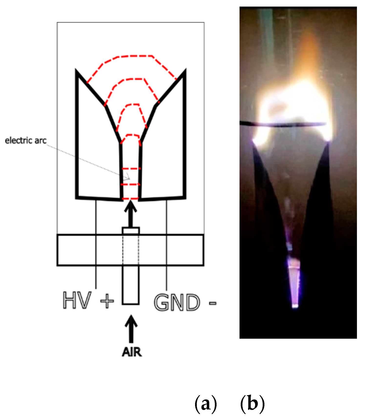
The low-temperature gliding arc plasma reactor is an innovative technology which can be used for the effective mitigation of gaseous and particulate pollutants, particularly those emanating from diesel exhaust emissions. This reactor utilizes principles of plasma physics to generate non-thermal plasma, consisting of various reactive species capable of decomposing a wide range of pollutants. The operation of a gliding arc plasma reactor begins with the ignition of an electric arc between a pair of diverging electrodes connected to a high-voltage power source (
Figure 1).
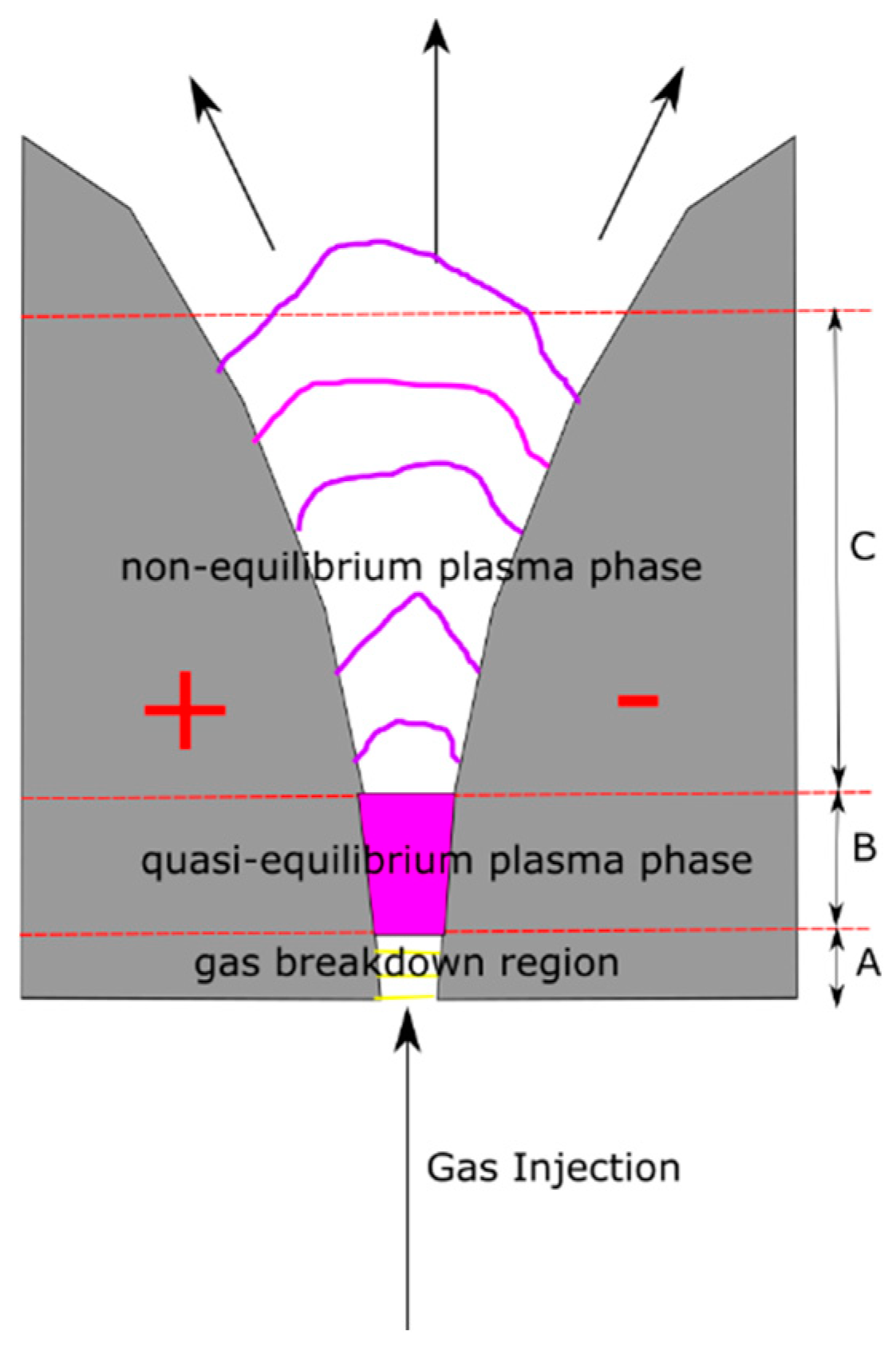
The application of high voltage ionizes the gas in the gap between the electrodes, forming an initial electric arc. (
Figure 2) The introduction of gas flow perpendicular to the arc axis causes the arc to glide along the length of the electrodes, elongating the arc and increasing the plasma volume. As the arc glides, it generates a non-equilibrium plasma characterized by a high electron temperature, which facilitates the creation of a variety of reactive species including ions, radicals, and excited molecules. These reactive species interact with pollutants in the gas stream, breaking molecular bonds and converting the pollutants into less harmful substances or completely oxidizing them to CO
2 and H
2O. The gliding arc plasma can be either thermal or non-thermal depending on the power and flow rate. Along with completely thermal and non-thermal modes, it is possible to operate the arc in the transitional regime when the discharge starts thermal, but during the space-time evolution becomes a non-thermal one. The powerful and energy-efficient transitional discharge combines the benefits of both equilibrium and non-equilibrium discharges.
Initial breakdown in gas at the distance of few millimeters between the two electrodes (
Figure 2) begins the dynamic cycle of the gliding arc. After about 1 μs, low-resistance plasma is formed and the voltage between the electrodes falls. The equilibrium stage occurs after the formation of the plasma channel. The gas flow pushes the plasma column with a velocity of about 10 m/s; their velocities, however, can be slightly different. The length (
l) of the arc increases together with voltage; the power increases up to the maximum value (
Pmax) provided by the power supply. During the quasi-equilibrium stage, the gas temperature does not change significantly (remaining around 3000 K). The non-equilibrium stage starts when the length of the gliding arc exceeds its critical value (
lcrit). Heat losses from the plasma column begin to exceed the energy supplied by the source, and it is not possible to sustain the plasma in quasi equilibrium. Then the plasma rapidly cools down to 1000 – 2000 K, while conductivity is sustained by high electron temperature, ~1 eV. After decay of the non-equilibrium discharge, a new breakdown takes place at the shortest distance between the electrodes and the cycle repeats [
11].
One of the primary advantages of gliding arc plasma reactors is their high decomposition efficiency, resulting from the enhanced interaction between reactive plasma species and pollutants. The reactor’s design, which promotes continuous movement of the arc, ensures a uniform distribution of reactive species, thereby maximizing pollutant degradation. Additionally, the reactor’s ability to operate at relatively low temperatures prevents the formation of secondary pollutants often associated with high-temperature processes and reduces thermal stress on reactor components. The non-thermal nature of the plasma ensures that most of the energy is concentrated in the electrons, allowing for efficient generation of reactive species without significantly increasing the gas temperature. The gliding arc discharge has higher current and higher electrical, as well as lower applied voltage compared to a glow or corona discharge. Therefore, gliding arc discharge ensures high reaction selectivity and energy conversion, while easily conquering the limit of both gas pressure and required energy input [
11].
Despite the promising applications of gliding arc plasma reactors, there are several limitations to consider. Maintaining a stable electric arc and sustaining the plasma requires significant energy input, which could be a limiting factor in large-scale applications. Furthermore, continuous operation leads to wear and degradation of the electrodes due to high-intensity electric arcing, necessitating routine maintenance and periodic replacement. In addition, the control and optimization of plasma properties and gas flow dynamics can be complex, requiring sophisticated control systems and a comprehensive understanding of the underlying plasma physics.
The plasma behavior within gliding arc reactors is crucial for optimizing reactor performance and pollutant degradation efficiency. The plasma operates in a non-equilibrium state, with electron temperatures significantly higher than those of the ions and neutral gas. This discrepancy facilitates efficient energy transfer to gas molecules, promoting dissociation and ionization processes essential for pollutant degradation. The dynamic nature of the gliding arc, characterized by its continuous motion along the electrodes, ensures a steady distribution of reactive species and enhances the interaction time between the plasma and pollutants. The high density of energetic electrons in the plasma promotes frequent collisions with gas molecules, generating a myriad of reactive species necessary for effective pollutant breakdown.
2.2. Characteristics of Diesel Engine and Utilized Fuel
Diesel exhaust particles were obtained from combustion of sulfur-free diesel oil in diesel engine. The fuel was always taken from one and the same gas station of the most popular petrol refiner and retailer in Poland. Characteristics of utilized fuel is given in
Table 1.
DEPs were generated with the use of the four-cylinder diesel engine Mercedes Benz 240D (1982) adapted to be used in a laboratory, on a motor test rig (engine displacement 2399 cm3, engine power 53 kW at 4200 rpm, torque 137 Nm at 2400 rpm). Motor emissions were generated under idle speed conditions.
2.3. Characteristics of Non-Thermal Plasma Reactor with Gliding arc Discharge
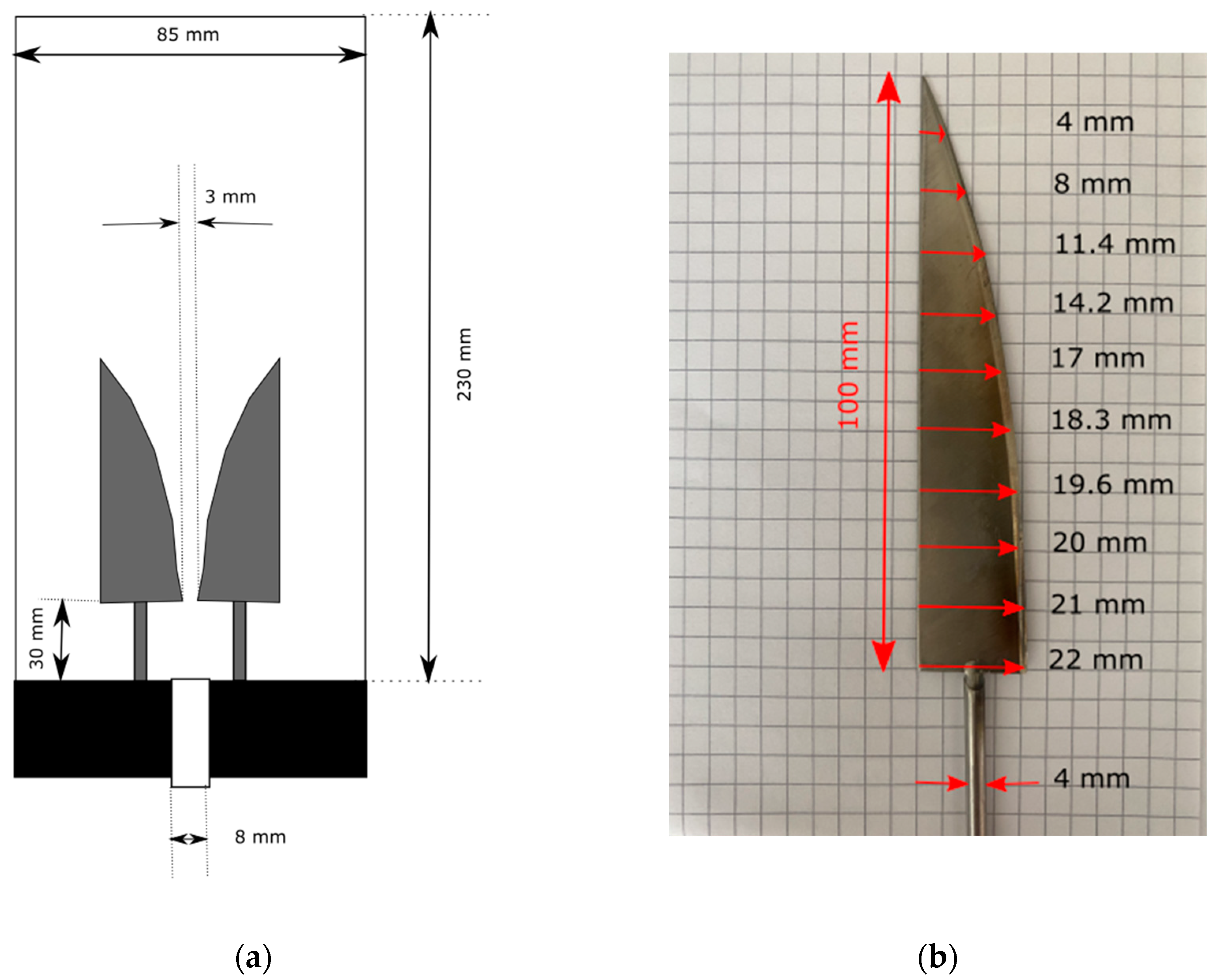
A conventional knifed-shaped LTP GA reactor was utilized for experimental purpose and is shown in
Figure 3a. Reactor’s wall was made of a glass tube and was thermally insulated, as it was proven to improve reactor’s energetic efficiency (however in DBD reactors). The plasma volume was calculated by knowing the volume of an inverted cone with height value equal to 120 mm and base radius equal to 23.5 mm (based on
Figure 3). The residence time in the plasma area (of and estimated volume equal to 69.4 cm
3) in the plasma reactor is 0.03 s, 0.06 s and 0.3 s when the flow rate of the exhaust gas is 140, 70 and 14 L/min, respectively. The LTP GA is equipped with two flat electrodes and their dimensions are presented in
Figure 3b. Knifed-shaped electrodes were sharpened at the end, their thickness’s value was 3 mm. They were made of acid-resistant stainless-steel type 1.4301/1.4307 (According to EN), 304 (According to AISI), 0H18N9 (According to PN). The reactor is equipped with the two AC high voltage SIET transformers (50 mA, 10 kV, Brollo siet, Caerano di San Marco TV, Italy) for the power supply (connected in parallel, 2x300 W). The electric power applied to our experimental setup was measured with a power meter. To drive the discharge an AC high voltage was generated with a maximum of 10 kV (rms). The frequency of applied voltage was 50 Hz. When a high voltage power supply is turned on, the gas flow initiates the gliding of the arc, thus forming GA plasma.
2.3. Experimental Setup
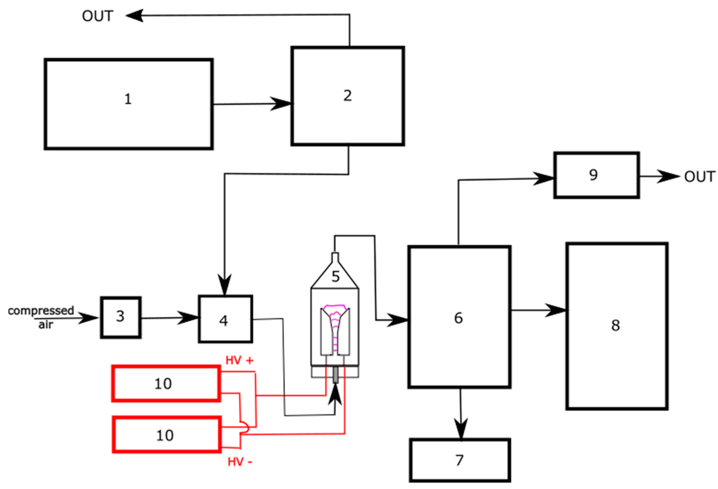
Figure 4 shows a schematic diagram of the experimental setup for testing the DEPs treatment system incorporating non-thermal plasma reactor with gliding arc discharge.
Diesel exhaust fumes containing DEPs produced by the diesel engine (1) were directed to the chamber (1 m3, 2) after they were stabilized in a buffer tank. Diesel engine and buffer tank were situated outside the building. The airflow was generated by a compressor and controlled by a mass flow controller (MFC) (SFC5500–200 slm, Sensirion, Zurich, Switzerland) (3). Leaving MFC, compressed air was at the first inlet of the mixing tee, where the suction nozzle (4) ensured the continuous sampling of diesel exhaust fumes from the chamber through the second inlet. Fumes were then diluted in the compressed air and entered the gliding arc LTP reactor (5). Dilution rate was dependent on the compressed airflow and its obtained values were: 1:0.05 for 140 L/min, 1:0.2 for 70 L/min and 1:0.15 for 14 L/min, respectively. Treated Diesel exhaust fumes containing DEPs were collected in chamber (6) prior testing. They were assayed in terms of their concentration and number particle size distribution using two spectrometers: (7) Grimm aerosol counter (Model 1.109, Grimm Aerosol Technik GmdH, Ainring, Germany) and (8) Fast Automotive Particles Emission Spectrometer—FAPES (Model 5.601, Grimm Aerosol Technik GmdH, Ainring, Germany). Exhaust gases were directed to waste using a fan (9). The reactor is equipped with the two AC high voltage SIET transformers (10).
2.4. Assessment of Time-Space Evolution of the Gliding arc Discharge
Firstly, gliding arc evolution with transition from quasi-thermal to non-thermal regime of the discharge in LTP reactor was measured using camera that made a series of consequent snapshots with the frequency of 30 Hz.
2.5. Measurement of DEPs’ Number Particle Concentration and Size Distribution
Secondly, the study encompassed the examination of particle number concentrations as a function of time.
Fast Automotive Particles Emission Spectrometer—FAPES (Model 5.601, Grimm GmbH, Germany) was utilized to assay the diesel exhaust fumes at the reactor’s outlet by measuring the concentration of DEPs particles in the range of 10 – 640 nm in size diameter. In this study, a sampling rate of 0,2 Hz was used. The measurement technique is based on 10 Differential Mobility Analyzers (DMAs) with in-line Faraday Cup Electrometers (FCEs).
The FAPES did not detect any particles from the range 370 – 640 nm due to their too low concentration. For this reason, the second spectrometer (Grimm Model 1.109, Germany) was used to determine the number particle size distribution and concentration of the DEPs particles in the gas leaving the reactor, in the range of 250 nm-32 µm. As it was stated before, the DEPs samples were diluted prior to measuring. It was due to the requirements of spectrometers that prevents them from damage caused by severe aerosol exposure.
3. Results
3.1.Assessment of Time-Space Evolution of the Gliding arc Discharge
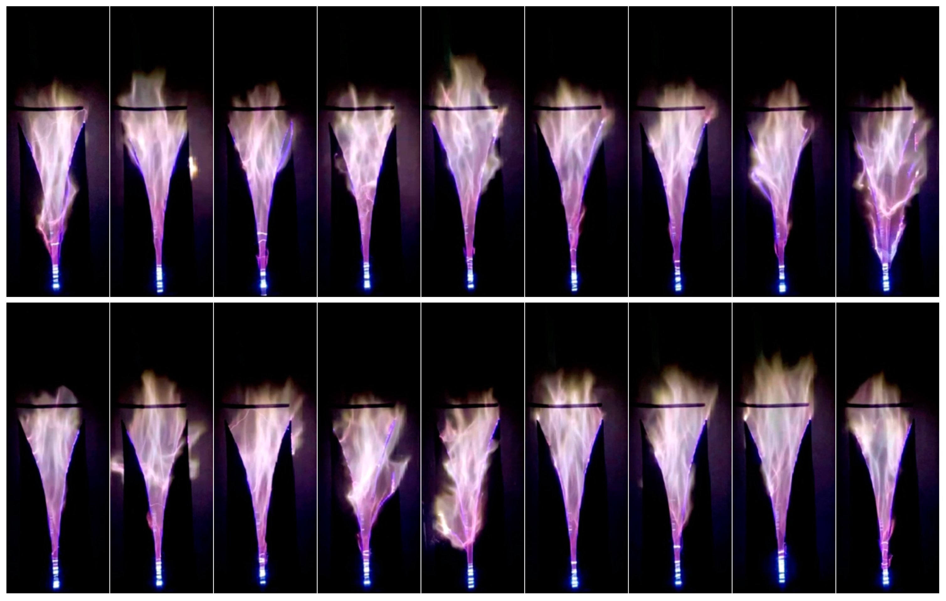
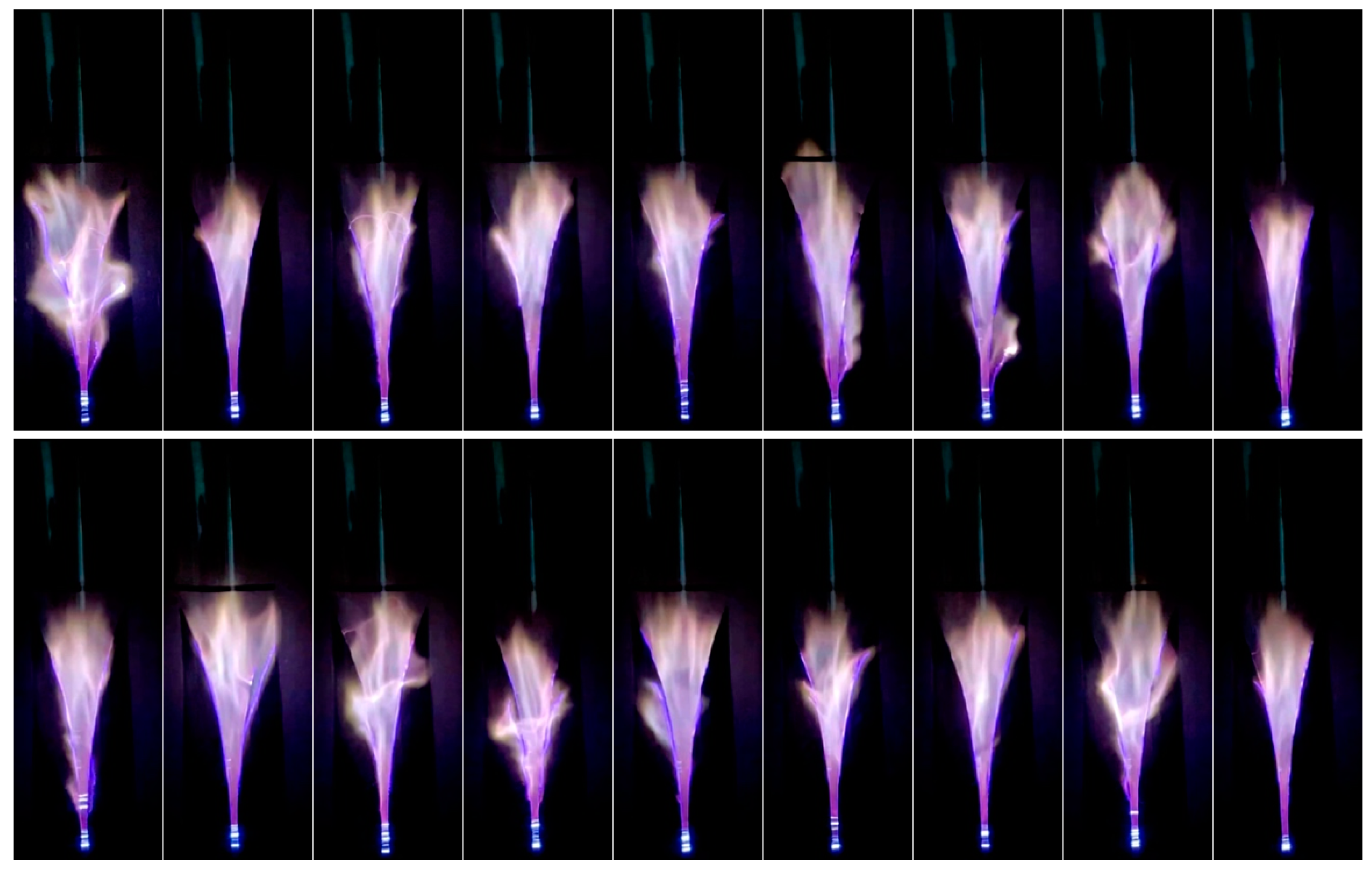
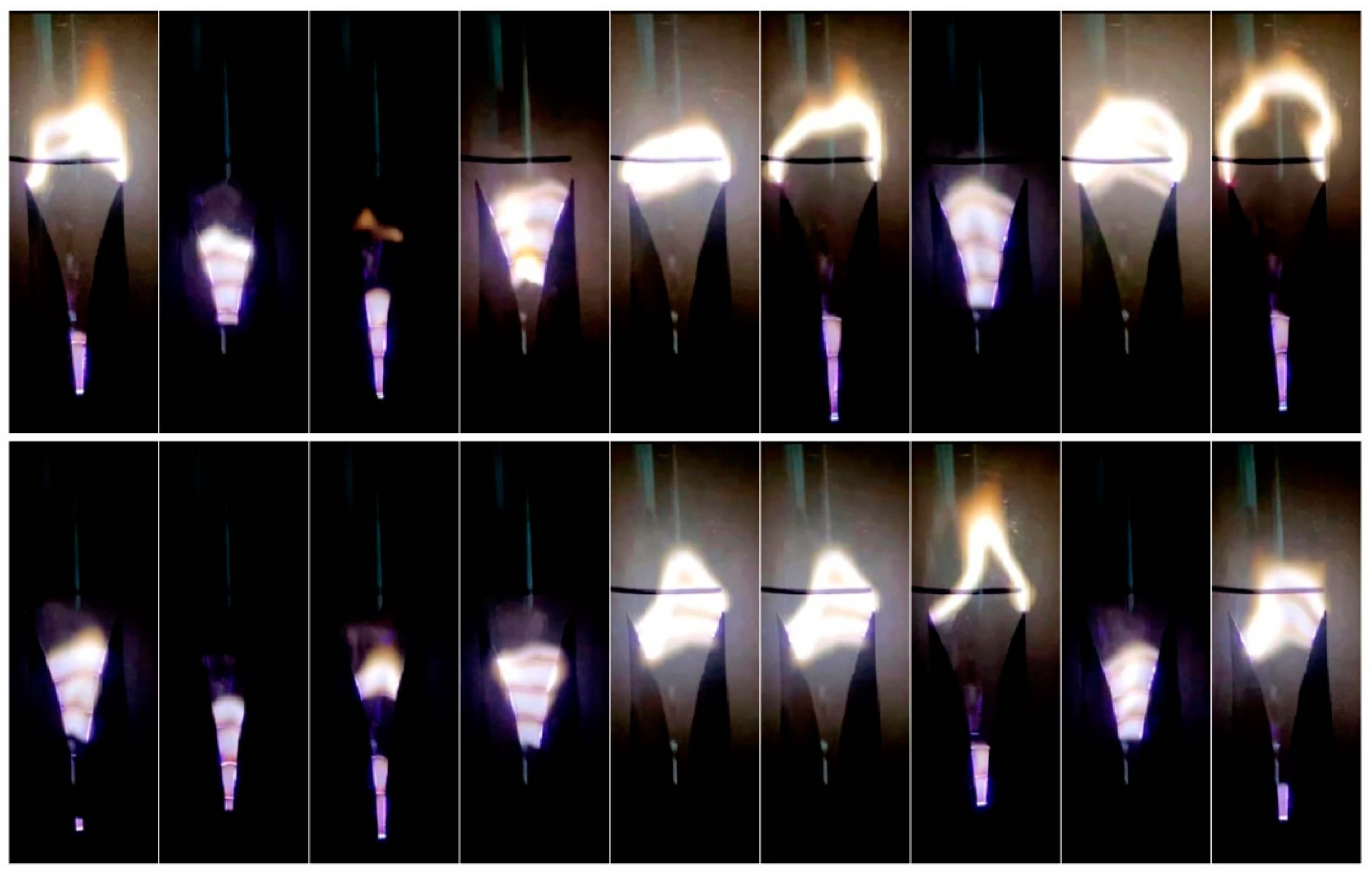
First of all, time-space evolutions of the gliding arc discharge in studied LTP reactor are illustrated in
Figure 5,
Figure 6 and
Figure 7, for 140 L/min, 70 L/min and 14 L/min, respectively, by a series of 18 snapshots per each studied flow with frequency of 30 Hz.
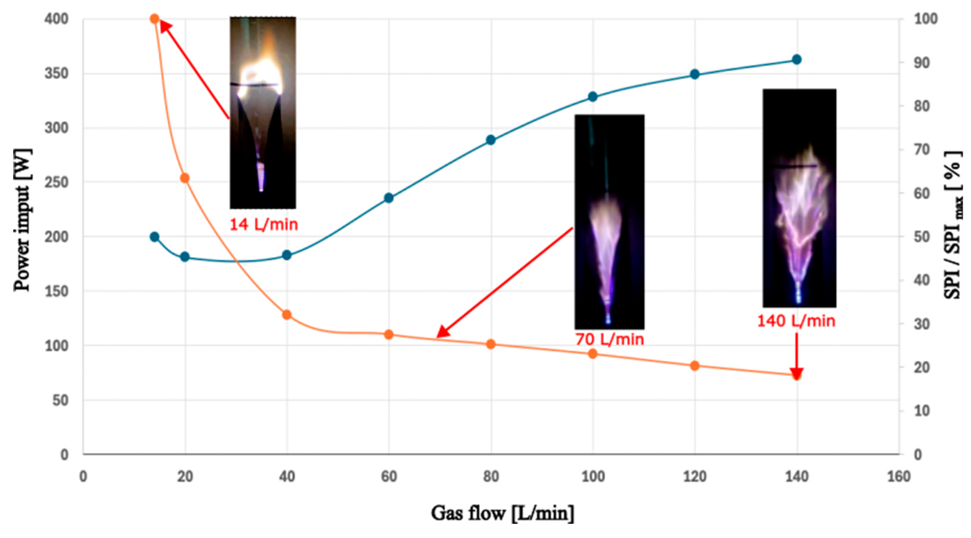
Secondly, two indicators of energetic yield in LTP GA reactor were discussed for the purpose of all three cases, namely for 14 L/min, 70 L/min and 140 L/min, being compared in further analysis of results. These were power input for DEPs removal and specific power input per molecule. For this reason, the specific power input per molecule (SPI) was normalized – as the ratio of power input in the studied case versus the highest power input obtained (SPI
max for the “14 L/min” case). The aforementioned results are shown in
Figure 8 and superimposed onto indicator’s presented trends are the chosen representative snapshots for every studied airflow.
3.2. Measurement of DEPs’ Number Particle Concentration and Size Distribution
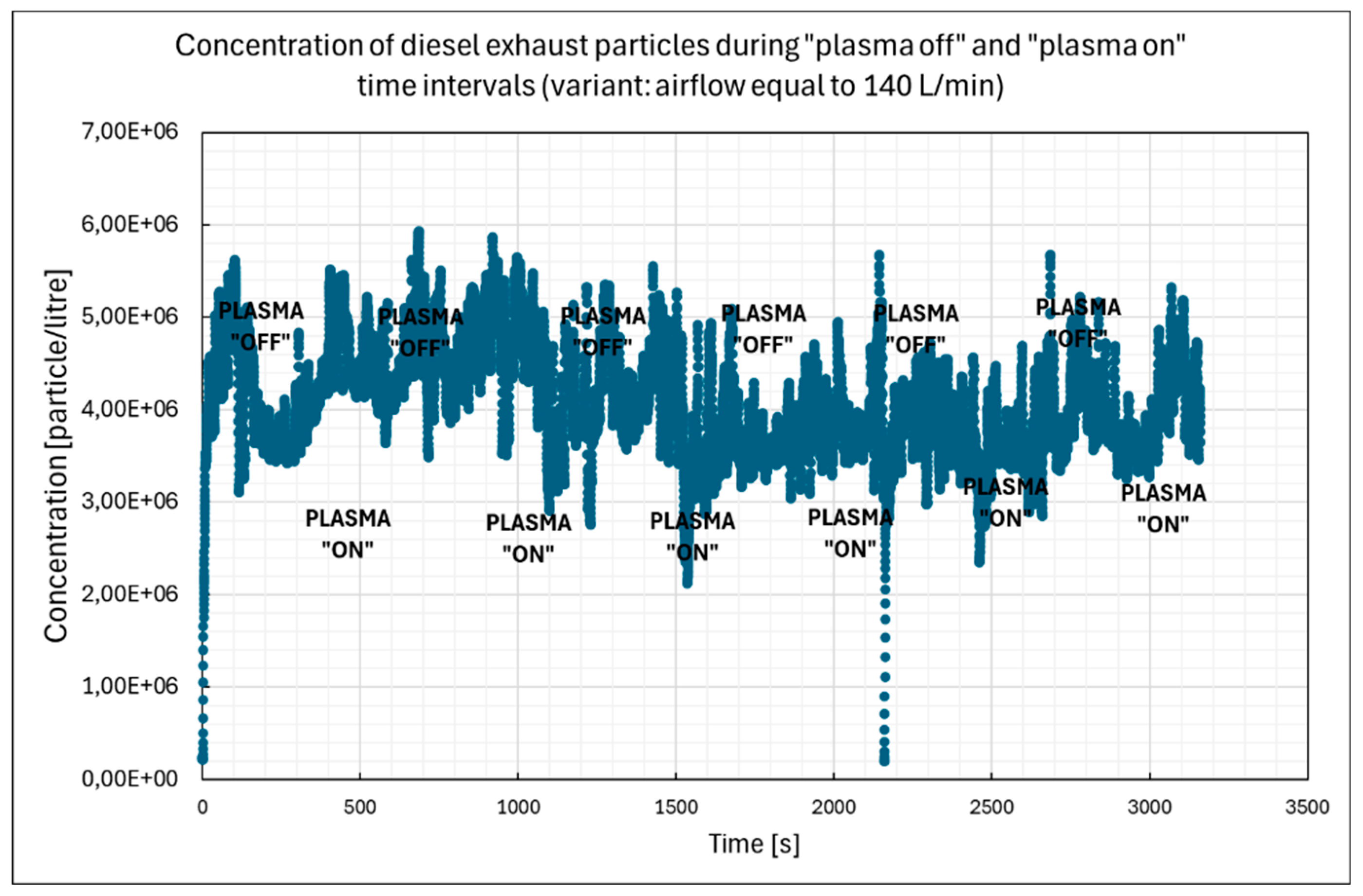
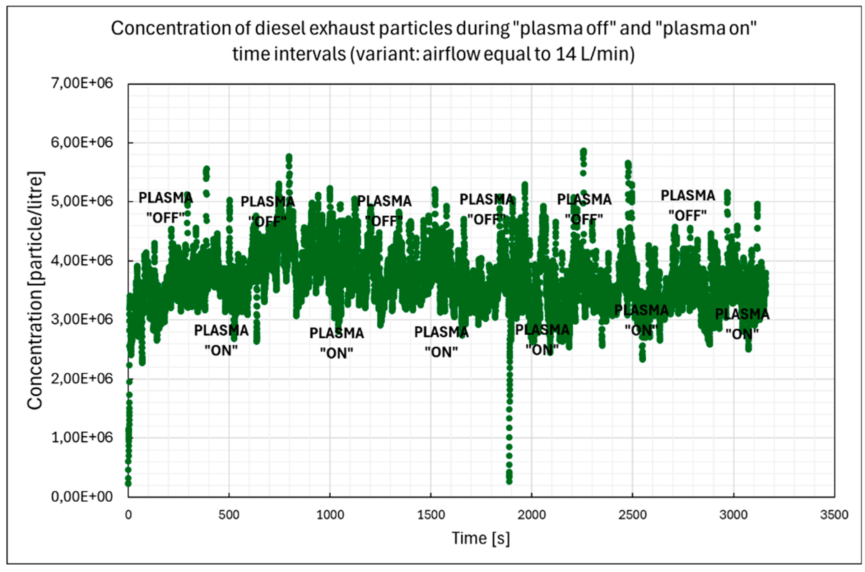
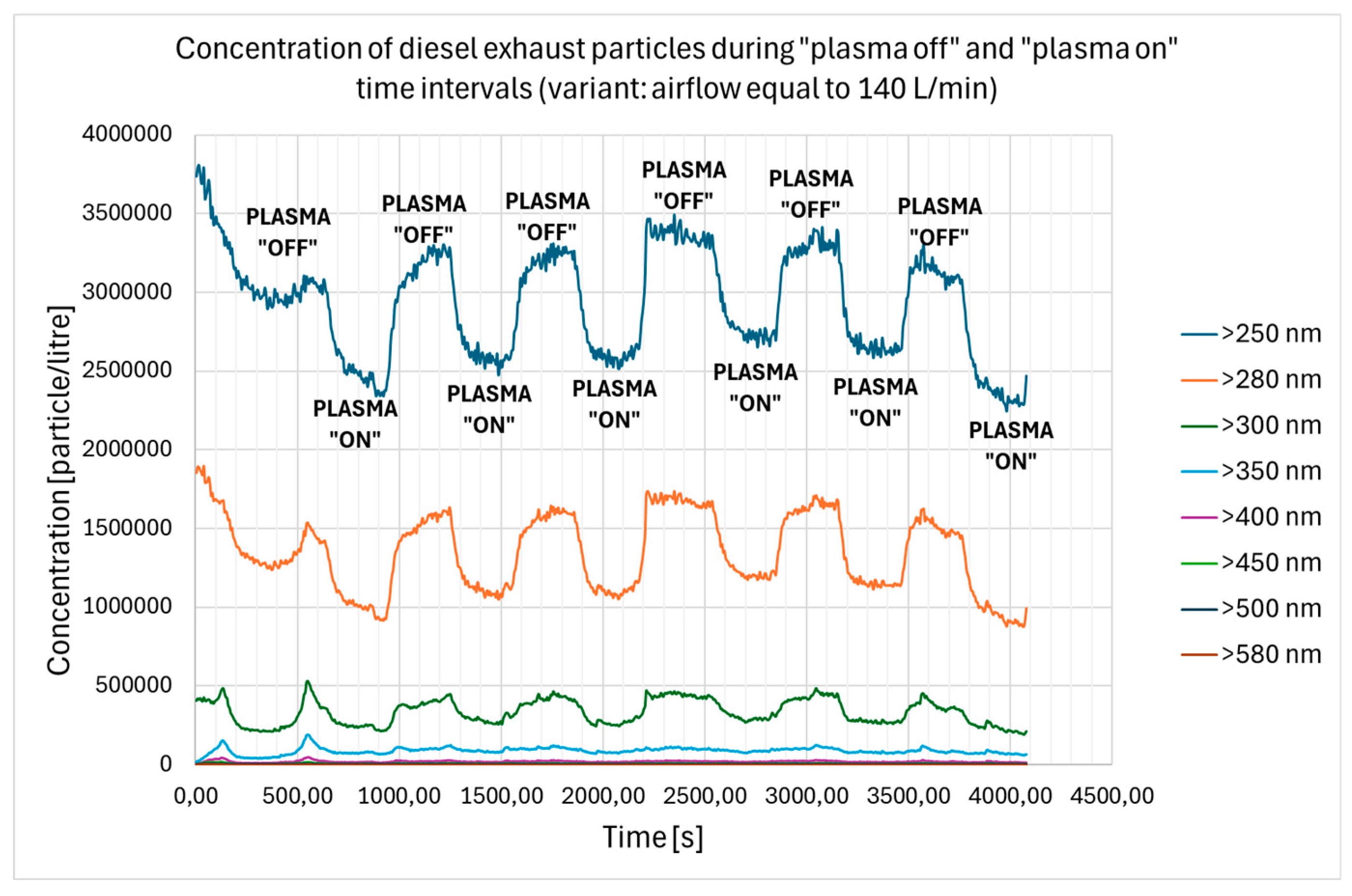
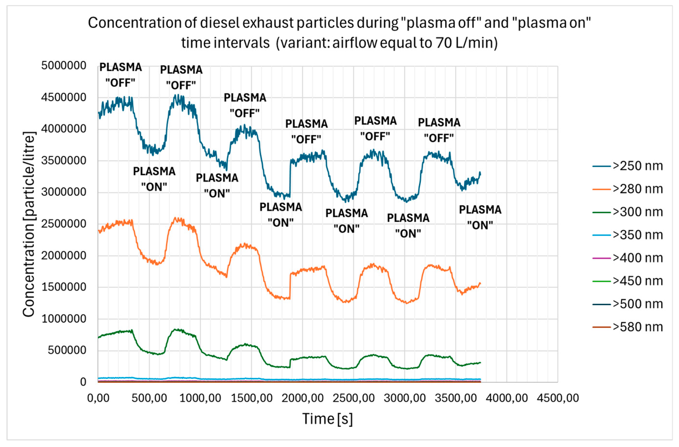
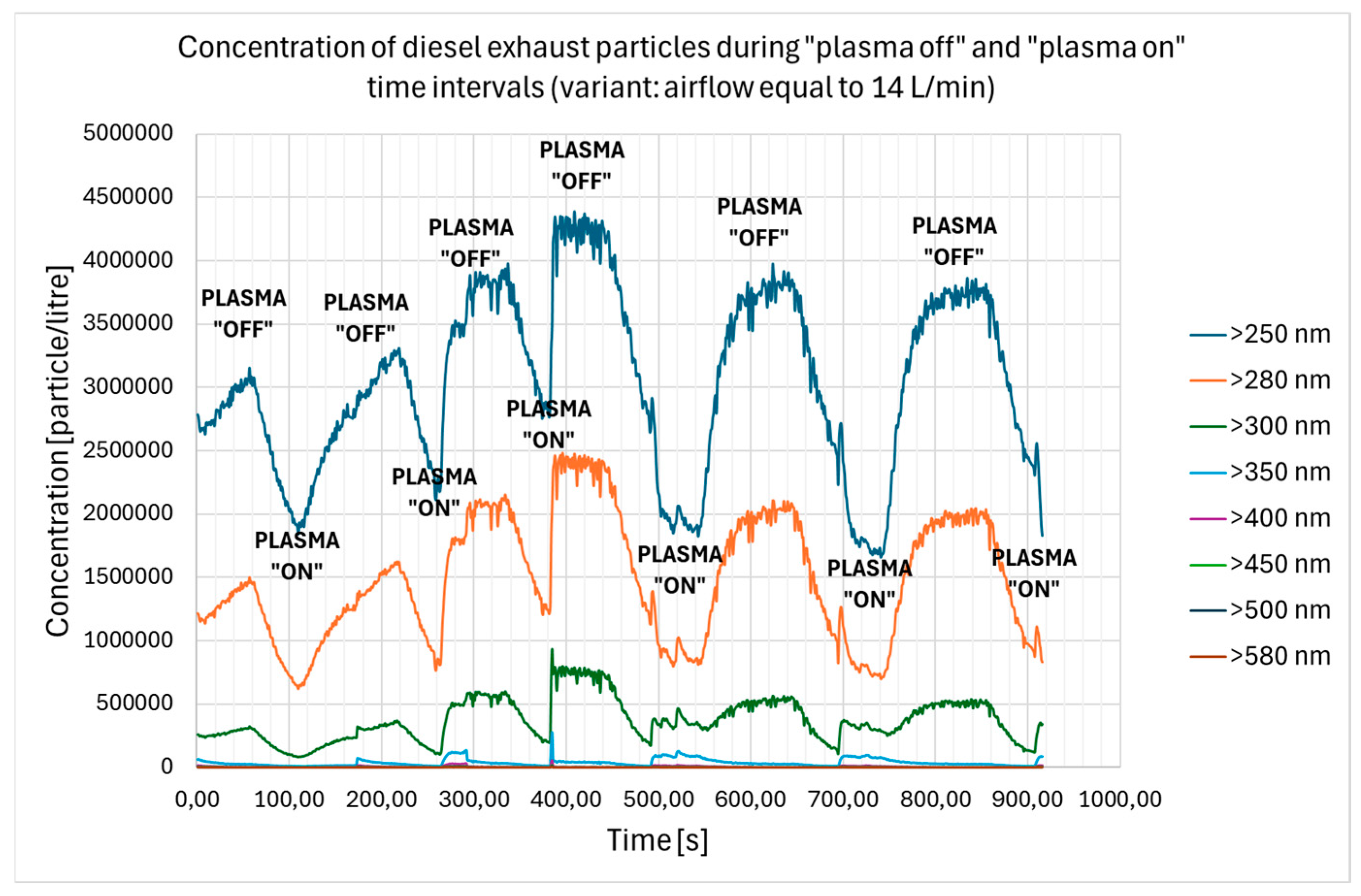
The total particle number concentrations were scrutinized in real time and presented in
Figure 9,
Figure 10,
Figure 11,
Figure 12,
Figure 13 and
Figure 14, so as to abundantly show the influence of plasma occurrence on the removal of DEPs particulates of different sizes. Hence, marked are the time periods of turning on and turning off the studied non-thermal plasma reactor with gliding arc discharge (“plasma on” and “plasma off”, respectively).
Moreover,
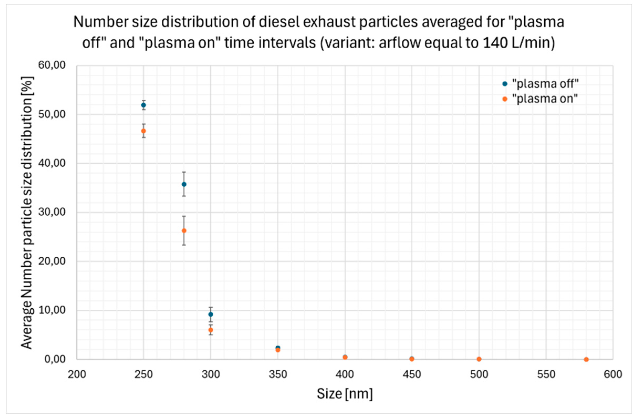
Figure 15,
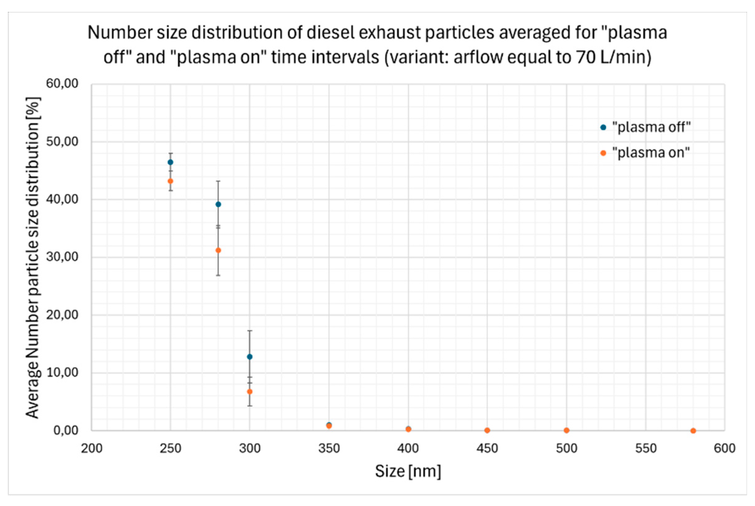
Figure 16,
Figure 17 and
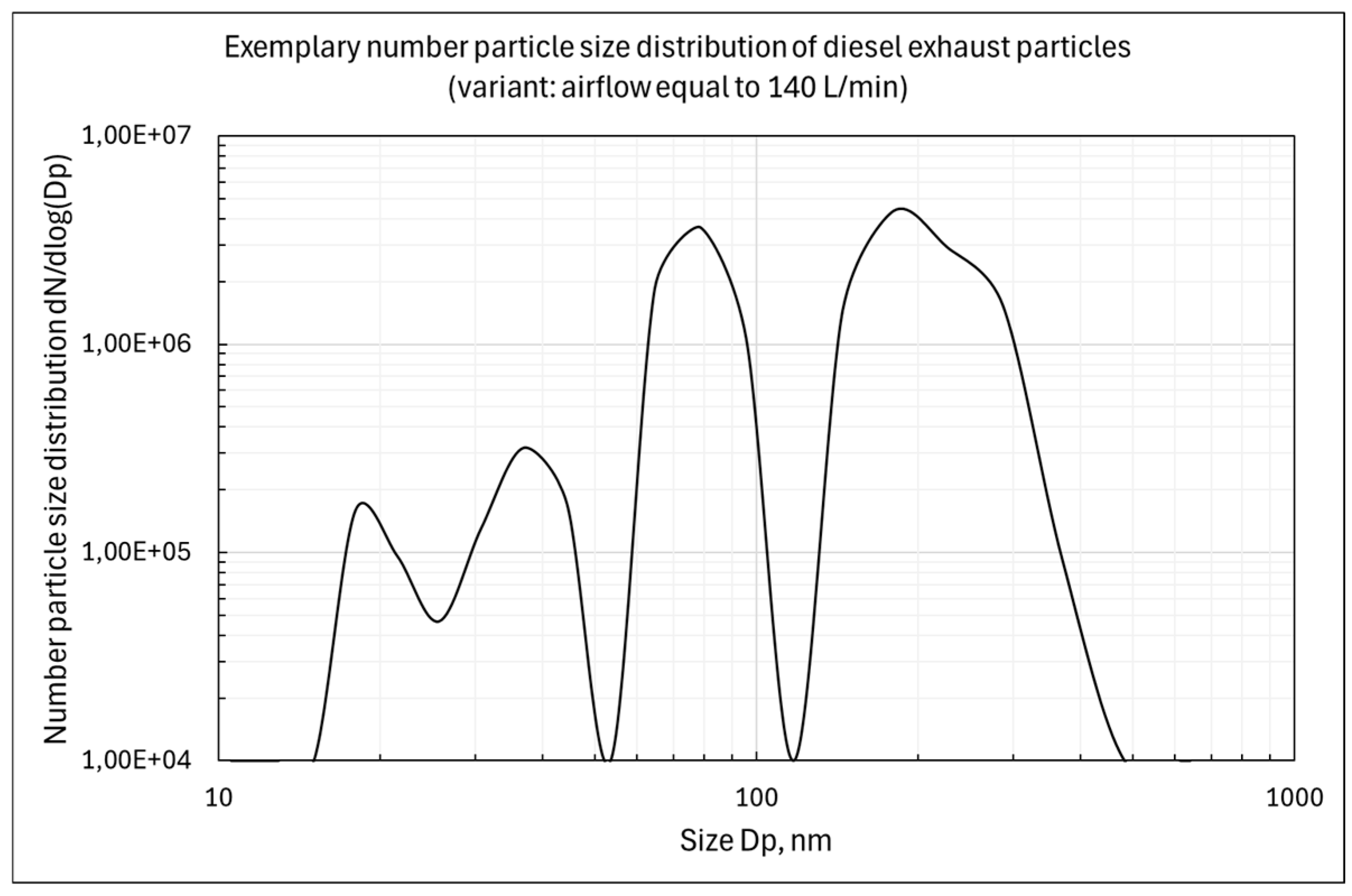
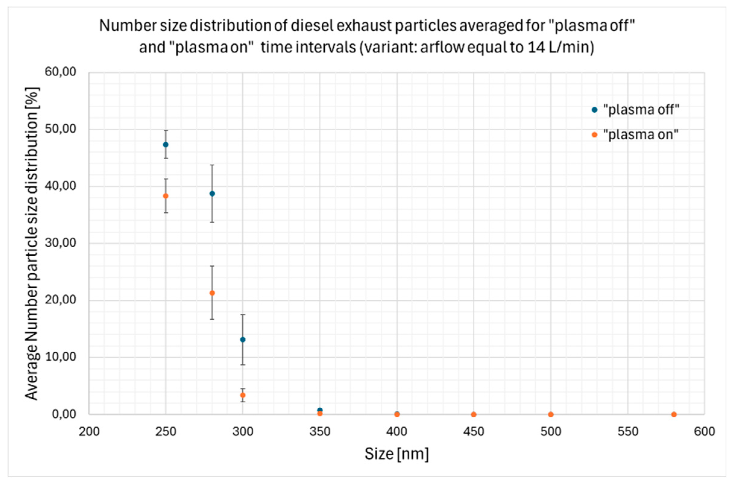
Figure 18 illustrate the number particle size distributions for two fractions of DEPs particulates: 10 – 250 nm (measured by FAPES spectrometer) and 250 – 580 nm (measured by Grimm 1.109 particle spectrometer). The concentration of particles higher that 580 nm was too low to draw any conclusions, thus they were not shown in the present work.
3.3. The Effectiveness of Gliding arc Non-Thermal Plasma Reactor in Removal of Nanoparticles from the Diesel Exhaust Fumes
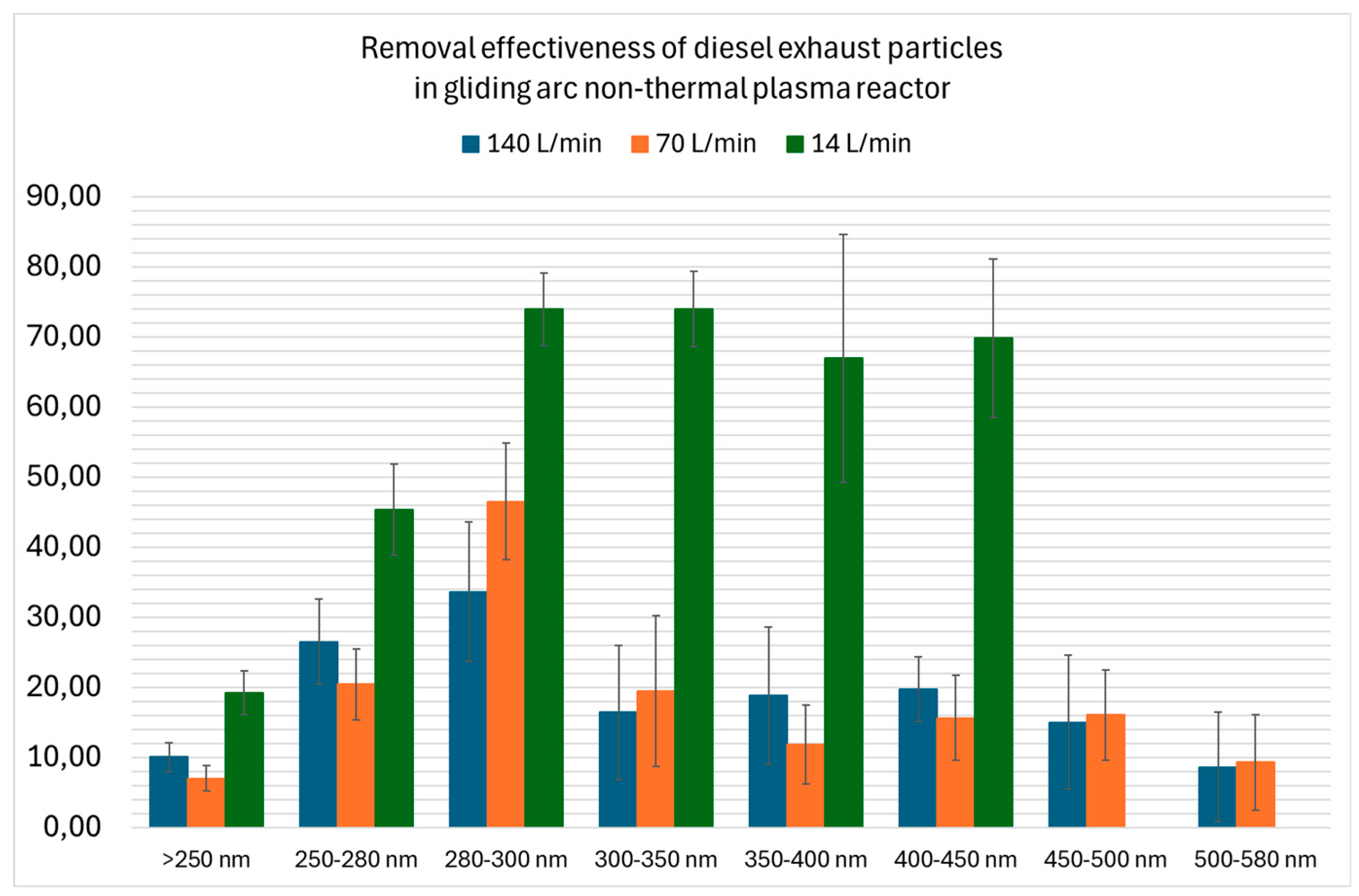
Next focus of the study is to discuss the effectiveness of gliding arc non-thermal plasma reactor in removal of nanoparticles from the diesel exhaust fumes. The findings, its mean values and standard deviation, attained for all studied airflows are presented collectively in
Figure 19 for particulates ranging from 250 to 580 nm in size.
4. Discussion
4.1. Assessment of Time-Space Evolution of the Gliding arc Discharge
First of all, from the
Figure 5–7, it appears that in the case of the lowest airflow rate, 14 L/min, the formed classic Jacob’s ladder is clearly visible. From the results obtained for the three studied flows it is observed that in both “70 L/min” and “140 L/min” cases the area of plasma channel reaches the lower level than in the “14 L/min” case. It also appears that the characteristics of plasma flow is more turbulent, and the color of nitrogen triplets (purple) is evident. The average residence time’s value would be by far higher, when the airflow drawing DEPs is lower (14 L/min). Based on the results in
Figure 8 the main observation is as follows: the higher the residence time’s value (the lower airflow’s value), the higher the energy input that may be successfully utilized for DEPs’ removal in the LTP reactor with gliding arc discharge.
3.2. Measurement of DEPs’ Number Particle Concentration and Size Distribution
In general, from the analysis of
Figure 9,
Figure 10 and
Figure 11,15 it is clear, that in every studied case the produced plasma state in the reactor had no effect on the number concentration, nor on the particle size distribution, of DEPs particulates being in the range from 10 to 250 nm. On the other hand, based on the graphs presented in
Figure 12,
Figure 13 and
Figure 14, 16–18 it was noted that reactor’s performance definitely lowered the concentration of bigger DEPs particulates in the range from 250 nm to 580 nm. It is reflected in the alterations of number size distribution of these particulates. Furthermore, it is also worth noting that the decrease in the value of airflow drawn through the reactor favors the removal of the DEPs particulates.
3.3. The Effectiveness of Gliding arc Non-Thermal Plasma Reactor in Removal of Nanoparticles from the Diesel Exhaust Fumes
Based on the findings presented in
Figure 19 it is clear, that decreasing flow rate from 140 L/min to 70 L/min somehow altered the values of effectiveness, but the results remained within statistical error margins and no trend was observed for increasing particle’s diameter. Achieving the airflow of 14 L/min led to a substantial improvement in removal’s effectiveness, corresponding even to an almost fourfold increase in this parameter for particles of 300 – 480 nm in size. Smaller particulates experienced removal increasing with their diameter, then a considerable, quick jump in the process effectiveness in the aforementioned size range, while bigger particles were absent in assessed aerosol cloud of diesel fumes.
The above analysis suggests that the differences between the results for studied airflows are associated with different residence time acting as a key attribute of the evaluated process.
For understanding the results of ongoing LTP GA plasma reactor’s performance, adequate discussion of major mechanisms governing DEP particulates’ removal must be provided. From the literature review mentioned in the introduction section it is known that the non-thermal DBD plasma reactor can affect the oxidation of particulate matter in diesel exhaust at low temperature and it can be detected that the diameter of the carbon particles became smaller, and the amount of C atoms was significantly reduced under the treatment of NTP technology. Further insight into the mechanisms occurring in other kind of NTP apparatuses, that is gliding arc reactor, must be gained in future research.
5. Conclusions
From the above analysis, it was clearly proven to be true that non-thermal plasma reactors with gliding arc discharge may be successfully adapted in the process of diesel exhaust particulates treatment. They can be a promising tool herein, since the low-pressure reduction of carbon particles at the level of the exhaust line is considered as one of the present challenges of the diesel engine.
Our findings underscore the promising potential of GA technology in reducing emissions of DEPs, improving the environmental impact of diesel engines, as well as improving the occupational safety and health level by ensuring the reduce of concentrations of airborne harmful DEPs particulates from the respirable size range.
Another message of the presented work is that the performance of non-thermal gliding arc reactors may be optimized by adjusting the airflow at the inlet of reactor, in such a way to guarantee the longest aerosol residence times and, thus, the highest DEPs’ removal efficiency. In future investigations the effect of flow rate on DEPs removal should be examined in detail. Specifically, experiments with lower flow rate of the air are needed on to obtain the solution for scalability of the treatment system, potentially consisting of multiple GA reactors connected in parallel.
Author Contributions
Conceptualization, A. D, A. P. and A. M.; methodology, A. D, A. P. and A. M.; software, A. M.; validation, A. D., A. P. and. A. M.; formal analysis, A. D, A. P. and A. M.; investigation, A. D, A. P. and A. M.; resources, A. D, A. P. and A. M.; data curation, A. D.; writing—original draft preparation, A. D. and A. M.; writing—review and editing, A. D, A. P. and A. M.; visualization, A. D, A. P. and A. M..; supervision, A. M.; project administration, A. M..; funding acquisition, A. M. All authors have read and agreed to the published version of the manuscript.
Funding
This research was financially supported by the Warsaw University of Technology under grant I-Chem.5 of the Scientific Council of Chemical Engineering.
Conflicts of Interest
The authors declare no conflicts of interest.
References
- Olabi, A. G.; Maizak, D.; Wilberforce, T. Review of the regulations and techniques to eliminate toxic emissions from diesel engine cars. Sci. Total Environ. 2020, 748, 141249. [Google Scholar] [CrossRef]
- Krishna, S. M.; Abdul Salam, P.; Tongroon, M.; Chollacoop, N. Performance and emission assessment of optimally blended biodiesel-diesel-ethanol in diesel engine generator. Appl. Therm. Eng. 2019, 155, 525–533. [Google Scholar] [CrossRef]
- Wang, Z.; Zhang, X.; Guo, J.; Hao, C.; Feng, Y. Particle emissions from a marine diesel engine burning two kinds of sulphur diesel oils with an EGR & scrubber system: Size, number & mass. Process Saf. Environ. Prot. 2022, 163, 94–104. [Google Scholar] [CrossRef]
- Matti Maricq, M. Chemical characterization of particulate emissions from diesel engines: A review. J. Aerosol Sci. 2007, 38, 1079–1118. [Google Scholar] [CrossRef]
- Brunekreef, B.; Holgate, S. T. Air pollution and health. The Lancet 2002, 360, 1233–1242. [Google Scholar] [CrossRef] [PubMed]
- IARC Working Group on the Evaluation of Carcinogenic Risks to Humans. Diesel and Gasoline Engine Exhausts and Some Nitroarenes. Lyon (FR): International Agency for Research on Cancer; 2014. (IARC Monographs on the Evaluation of Carcinogenic Risks to Humans, No. 105.). Available online: https://www.ncbi.nlm.nih.gov/books/NBK294269/ (accessed on 4 July 2024).
- Pope, C. A.; et al. Lung cancer, cardiopulmonary mortality, and long-term exposure to fine particulate air pollution. JAMA 2002, 287, 1132–1141. [Google Scholar] [CrossRef] [PubMed]
- Penconek, A.; Moskal, A. Deposition of diesel exhaust particles from various fuels in a cast of human respiratory system under two breathing patterns. J. Aerosol Sci. 2013, 63, 48–59. [Google Scholar] [CrossRef]
- Yamasaki, H.; Shidara, A.; Shimidzu, Y.; Kuroki, T.; Kim, H. J.; Okubo, M. In-flight diesel particulate matter removal using nonthermal plasma filtering. Int. J. Plasma Environ. Sci. Technol. 2020, 2020 14, 1–13. [Google Scholar] [CrossRef]
- Starikovskiy, A.; Aleksandrov, N. Plasma-assisted ignition and combustion. Prog. Energy Combust. Sci. 2013, 39, 61–110. [Google Scholar] [CrossRef]
- Fridman, A. Plasma chemistry; Cambridge university press: New York, USA, 2008; pp. 1–978. [Google Scholar]
- Chae, J. O. Non-thermal plasma for diesel exhaust treatment. J. Electrostat. 2003, 57, 251–262. [Google Scholar] [CrossRef]
- Thomas, S. E.; Martin, A. R.; Raybone, D.; Shawcross, J. T.; Ng, K. L.; Beech, P.; Whitehead, J. C. Non Thermal Plasma Aftertreatment of Particulates Theoretical Limits and Impact on Reactor Design. SAE Transactions, 2000, 109, 1594–1606. [Google Scholar]
- Pan, W.; Yixi, C.; Jun, W.; Rongyao, Z.; Yazhou, Y. Carbon particles reduction in diesel engine with non-thermal plasma technology. Proc. - Int. Conf. Electr. Control Eng. ICECE 2010, 2010, 3447–3449. [Google Scholar] [CrossRef]
- Zhu, K.; Cai, Y.; Shi, Y.; Lu, Y.; Zhou, Y.; He, Y. The effect of nonthermal plasma on the oxidation and removal of particulate matter under different diesel engine loads. Plasma Process. Polym. 2022, 19, 1–9. [Google Scholar] [CrossRef]
Figure 1.
Scheme of gliding arc plasma reactor (a) and picture of gliding arc formatted in working reactor (b).
Figure 1.
Scheme of gliding arc plasma reactor (a) and picture of gliding arc formatted in working reactor (b).
Figure 2.
Evolution of a gliding arc discharge: A) region of gas breakdown; B) quasi-equilibrium plasma phase; C) non-equilibrium plasma phase.
Figure 2.
Evolution of a gliding arc discharge: A) region of gas breakdown; B) quasi-equilibrium plasma phase; C) non-equilibrium plasma phase.
Figure 3.
Schematic diagram of a knifed-shaped non-thermal plasma reactor with gliding discharge utilized throughout the study (a) and geometry o a reactors’ knife (b).
Figure 3.
Schematic diagram of a knifed-shaped non-thermal plasma reactor with gliding discharge utilized throughout the study (a) and geometry o a reactors’ knife (b).
Figure 4.
Schematic diagram of the experimental setup: 1 – Diesel engine; 2 – Exhaust gas collecting chamber; 3 – Mass flow controller; 4 – Vacuum pump; 5 – Plasma Reactor; 6 – Collecting chamber; 7 – Grimm aerosols spectrometer; 8 – FAPES aerosol particle spectrometer; 9 – Exhaust fan; 10 – High voltage transformer.
Figure 5.
Time-space evolutions of the gliding arc discharge in studied LTP reactor for “140 L/min” case.
Figure 5.
Time-space evolutions of the gliding arc discharge in studied LTP reactor for “140 L/min” case.
Figure 6.
Time-space evolutions of the gliding arc discharge in studied LTP reactor for “70 L/min” case.
Figure 6.
Time-space evolutions of the gliding arc discharge in studied LTP reactor for “70 L/min” case.
Figure 7.
Time-space evolutions of the gliding arc discharge in studied LTP reactor for “14 L/min” case.
Figure 7.
Time-space evolutions of the gliding arc discharge in studied LTP reactor for “14 L/min” case.
Figure 8.
Power input and normalized specific power input per molecule as a function of gas flow.
Figure 8.
Power input and normalized specific power input per molecule as a function of gas flow.
Figure 9.
Time evolutions of number particle size distributions of nanoparticles having 10-250 nm in size during the DEP treatment using gliding arc discharge in studied LTP reactor for the “140 L/min” case.
Figure 9.
Time evolutions of number particle size distributions of nanoparticles having 10-250 nm in size during the DEP treatment using gliding arc discharge in studied LTP reactor for the “140 L/min” case.
Figure 10.
Time evolutions of number particle size distributions of nanoparticles having 10-250 nm in size during the DEP treatment using gliding arc discharge in studied LTP reactor for the “70 L/min” case.
Figure 10.
Time evolutions of number particle size distributions of nanoparticles having 10-250 nm in size during the DEP treatment using gliding arc discharge in studied LTP reactor for the “70 L/min” case.
Figure 11.
Time evolutions of number particle size distributions of nanoparticles having 10 - 250 nm in size during the DEP treatment using gliding arc discharge in studied LTP reactor for the “14 L/min” case.
Figure 11.
Time evolutions of number particle size distributions of nanoparticles having 10 - 250 nm in size during the DEP treatment using gliding arc discharge in studied LTP reactor for the “14 L/min” case.
Figure 12.
Time evolutions of number particle size distributions of nanoparticles having 250 - 580 nm in size during the DEP treatment using gliding arc discharge in studied LTP reactor for the “140 L/min” case.
Figure 12.
Time evolutions of number particle size distributions of nanoparticles having 250 - 580 nm in size during the DEP treatment using gliding arc discharge in studied LTP reactor for the “140 L/min” case.
Figure 13.
Time evolutions of number particle size distributions of nanoparticles having 250 - 580 nm in size during the DEP treatment using gliding arc discharge in studied LTP reactor for the “70 L/min” case.
Figure 13.
Time evolutions of number particle size distributions of nanoparticles having 250 - 580 nm in size during the DEP treatment using gliding arc discharge in studied LTP reactor for the “70 L/min” case.
Figure 14.
Time evolutions of number particle size distributions of nanoparticles having 250 - 580 nm in size during the DEP treatment using gliding arc discharge in studied LTP reactor for the “14 L/min” case.
Figure 14.
Time evolutions of number particle size distributions of nanoparticles having 250 - 580 nm in size during the DEP treatment using gliding arc discharge in studied LTP reactor for the “14 L/min” case.
Figure 15.
Instantaneous, exemplary number particle size distribution of smaller DEP particles investigated for the “140 L/min” case.
Figure 15.
Instantaneous, exemplary number particle size distribution of smaller DEP particles investigated for the “140 L/min” case.
Figure 16.
Number particle size distribution of DEP particles having 250 – 580 nm in size, averaged for “plasma off” and “plasma on” time intervals investigated for the “140 L/min” case.
Figure 16.
Number particle size distribution of DEP particles having 250 – 580 nm in size, averaged for “plasma off” and “plasma on” time intervals investigated for the “140 L/min” case.
Figure 17.
Number particle size distribution of DEP particles having 250 – 580 nm in size, averaged for “plasma off” and “plasma on” time intervals investigated for the “70 L/min” case.
Figure 17.
Number particle size distribution of DEP particles having 250 – 580 nm in size, averaged for “plasma off” and “plasma on” time intervals investigated for the “70 L/min” case.
Figure 18.
Number particle size distribution of DEP particles having 250 – 580 nm in size, averaged for “plasma off” and “plasma on” time intervals investigated for the “14 L/min” case.
Figure 18.
Number particle size distribution of DEP particles having 250 – 580 nm in size, averaged for “plasma off” and “plasma on” time intervals investigated for the “14 L/min” case.
Figure 19.
Removal effectiveness of diesel exhaust particles in non-thermal plasma reactor with gliding arc discharge.
Figure 19.
Removal effectiveness of diesel exhaust particles in non-thermal plasma reactor with gliding arc discharge.
Table 1.
Fuel characteristics.
Table 1.
Fuel characteristics.
| Parameter |
Unit |
Value |
| Cetane number |
- |
Min. 51 |
| Cetane index |
- |
Min. 46 |
| Density at 150C |
kg/m3
|
820.0 – 845.0 |
| Kinematic viscosity at 400C |
mm2/s |
2.0 – 4.5 |
| PAH (polycyclic aromatic hydrocarbons) content |
% (m/m) |
<7 |
| Sulfhur content, mg/kg |
mg/kg |
<10 |
| Fatty acids methyle esters content |
% (v/v) |
<7 |
|
Disclaimer/Publisher’s Note: The statements, opinions and data contained in all publications are solely those of the individual author(s) and contributor(s) and not of MDPI and/or the editor(s). MDPI and/or the editor(s) disclaim responsibility for any injury to people or property resulting from any ideas, methods, instructions or products referred to in the content. |
© 2024 by the authors. Licensee MDPI, Basel, Switzerland. This article is an open access article distributed under the terms and conditions of the Creative Commons Attribution (CC BY) license (http://creativecommons.org/licenses/by/4.0/).
