Preprint
Article

Enhancing Smart City Connectivity: a Multi-Metric CNN-LSTM beamforming based Approach to Optimize Dynamic Source Routing in 6G Networks for MANETs and VANETs

Altmetrics

Downloads

141

Views

48

Comments

0

A peer-reviewed article of this preprint also exists.

This version is not peer-reviewed

Submitted:

15 July 2024

Posted:

15 July 2024

You are already at the latest version

Alerts
Abstract
The advent of Sixth Generation (6G) wireless technologies introduces challenges and opportunities for Mobile Ad Hoc Networks (MANETs) and Vehicular Ad Hoc Networks (VANETs), necessitating a reevaluation of traditional routing protocols. This paper introduces the Multi-Metric Scoring Dynamic Source Routing (MMS-DSR), a novel enhancement of the Dynamic Source Routing (DSR) protocol, designed to meet the demands of 6G-enabled MANETs and the dynamic environments of VANETs. MMS-DSR integrates advanced technologies and methodologies to enhance routing performance in dynamic scenarios. Key among these is the use of a CNN-LSTM based beamforming algorithm, which optimizes beamforming vectors dynamically, exploiting spatial-temporal variations characteristic of 6G channels. This enables MMS-DSR to adapt beam directions in real-time based on evolving network conditions, improving link reliability and throughput. Furthermore, MMS-DSR incorporates a multi-metric scoring mechanism that evaluates routes based on multiple QoS parameters, including latency, bandwidth, and reliability, enhanced by the capabilities of Massive MIMO and the IEEE 802.11ax standard. This ensures route selection is context-aware and adaptive to changing dynamics, making it effective in urban settings where vehicular and mobile nodes coexist. Additionally, the protocol uses machine learning techniques to predict future route performance, enabling proactive adjustments in routing decisions. The integration of dynamic beamforming and machine learning allows MMS-DSR to effectively handle the high mobility and variability of 6G networks, offering a robust solution for future wireless communications, particularly in smart cities.
Keywords: 
Subject: Computer Science and Mathematics  -   Computer Networks and Communications

1. Introduction

Mobile Ad Hoc Networks (MANETs) have evolved from a specialized area of study into a ubiquitous element of modern wireless communications, playing a crucial role in the development of smart cities. Initially engineered for tactical military communications, their adaptability and resilience have expanded their applications to include disaster recovery, remote sensing, and complex multi-layered Internet of Things (IoT) ecosystems—key components of urban infrastructure.
As the urban environment becomes increasingly connected, Vehicular Ad Hoc Networks (VANETs) emerge as a critical subset of MANETs, specially designed for the fast-moving nature of vehicular networks [1,2,3]. VANETs enable vehicles to communicate with each other and with roadside infrastructure, facilitating not only improved traffic management but also enhancing safety and supporting a range of services from navigation to automated driving in smart cities [4,5,6].
As we brace for the advent of Sixth Generation (6G) wireless technologies, the scope and scale of both MANETs and VANETs are set for a transformative overhaul, especially within urban environments. Unlike previous generations, 6G is not just an incremental improvement but represents a seismic shift in wireless communication capabilities. It promises ultra-low latency levels, down to the sub-millisecond range, unprecedented data rates reaching terabits per second, and near-perfect reliability [7,8]. These features are expected to support futuristic applications crucial for smart cities, such as real-time augmented and virtual reality, machine-to-machine communications, ultra-reliable low-latency services, and the tactile Internet, which have extreme demands on network performance.
However, the transition to 6G introduces significant challenges, particularly for the inherently complex and dynamic networks like MANETs and VANETs in urban settings [9,10,11]. Traditional routing protocols, such as Dynamic Source Routing (DSR), are proving inadequate in this context. Designed in an era where network demands were less stringent, these protocols often rely on simplistic metrics like hop count for route selection, which is insufficient in the multi-dimensional Quality of Service (QoS) requirements of 6G, where latency, bandwidth, reliability, and energy efficiency are critical factors that must be simultaneously optimized [12,13,14,15].
To address these challenges, we introduce MMS-DSR (Multi-Metric Scoring Dynamic Source Routing), a groundbreaking modification and improvement of the traditional DSR protocol, tailored specifically for the nuanced demands of 6G-enabled MANETs and optimized for the high-speed, highly mobile environments of VANETs in smart cities. MMS-DSR incorporates several innovative features, including the use of Massive MIMO technologies and the IEEE 802.11ax standard. Massive MIMO, with its ability to handle multiple transmit and receive antennas, offers substantial gains in data rates and link reliability. The IEEE 802.11ax standard, on the other hand, brings improvements in network efficiency and capacity, especially in environments with a high density of connected devices.
In addition to these advancements, we enhance MMS-DSR by integrating a CNN-LSTM based beamforming algorithm. This enhancement is designed to optimize the beamforming vectors dynamically, a critical aspect in 6G networks to adapt to rapid spatial-temporal variations in the channel. By taking advantage of the capabilities of Convolutional Neural Networks (CNNs) to extract spatial features and Long Short-Term Memory (LSTM) networks to account for temporal dependencies, our approach adapts the beamforming vectors in real-time based on the evolving network conditions.
This adaptive beamforming capability is particularly important in the context of 6G’s use of Massive MIMO systems, where the ability to dynamically direct beams can significantly enhance signal quality and network performance. The integration of this beamforming algorithm into MMS-DSR means that the protocol is not only making intelligent decisions based on multi-metric scores but also considering the optimal beamforming directions to improve link reliability and data rates in the complex urban features of smart cities.
Our paper makes several significant contributions to the field of MANET and VANET routing for 6G networks in the context of smart cities.
  • Development of an Advanced Multi-Metric Scoring Mechanism: we introduce a novel scoring algorithm that uses the properties of Massive MIMO and the 802.11ax standard. This algorithm evaluates routes based on a comprehensive set of QoS metrics, providing a nuanced and context-aware route selection process optimized for urban environments.
  • Introduction of Machine Learning Techniques: by incorporating sophisticated machine learning algorithms, MMS-DSR predicts future route qualities based on historical data, enabling proactive route optimization. This is particularly useful in smart cities where predicting and adapting to changing conditions can significantly improve network performance.
  • Integration of a CNN-LST Based Beamforming Algorithm: we enhance MMS-DSR with a beamforming optimization algorithm that dynamically adjusts beamforming vectors. This integration helps in managing the spatial-temporal variations in the channel, supporting the complex beamforming needs of Massive MIMO systems in 6G.
  • Empirical Validation in a Smart City Simulation Environment: we validate the performance of MMS-DSR through extensive simulations using the INET framework along with the OSG Earth visualizer in OMNeT++. This simulation environment provides a realistic backdrop that highlights the protocol’s potential benefits for smart city applications, demonstrating its robustness and efficiency in a variety of challenging urban 6G scenarios.

Highlights

To increase the discoverability and readability of our work, we provide a brief overview of the main findings and their implications:
  • MMS-DSR integrates advanced machine learning techniques and beamforming to optimize routing in 6G-enabled MANETs and VANETs.
  • The protocol demonstrates significant improvements in throughput, latency, and routing overhead compared to traditional routing protocols.
  • MMS-DSR’s ability to adapt to real-time network conditions makes it highly suitable for dynamic urban environments.
  • The reduction in routing overhead and enhanced scalability positions MMS-DSR as a robust solution for future smart city applications.
The reminder of this paper is structured as follows: Section 2 reviews related work, illustrating the conceptual gaps that our research aims to fill. Section 3 provides main preliminary features in order to understand the purpose and the main concepts presented in the paper. Section 4 details the MMS-DSR protocol, including its architecture and the integration of the beamforming algorithm. Section 5 presents CNN-LSTM model architecture used in this proposal argued by a mathematical discussion. Section 6 explains how the proposed approach could be adapted for VANET and Section 7 describes the considered scenario related to experimental section. Section 8 showcases the results from our simulation studies in the urban smart city chosen context. Finally, Section 9 concludes the paper and outlines the roadmap for future research in this domain. Table 1 includes the list of main symbols used in the paper.

2. Related Works

The burgeoning field of Mobile Ad Hoc Networks has seen a plethora of routing protocols, each with its unique set of features and performance optimizations. However, few have addressed the challenges and opportunities posed by emerging 6G technologies as comprehensively as the MMS-DSR protocol presented in this paper.
The study [16], introduces a DSR protocol enhanced with MET-MFO techniques. This approach focuses on optimizing route discovery and maintenance processes to reduce execution time and improve routing efficiency. The use of MET-MFO allows for better handling of network dynamics and enhances the overall performance of the routing protocol in MANETs by minimizing delays and improving route stability. Our MMS-DSR protocol, however, advances this by using machine learning to predict and adapt to network changes dynamically and optimizing multiple metrics beyond execution time, such as latency, bandwidth, and reliability, offering a more comprehensive performance improvement.
The article [17] presents a routing protocol that evaluates routes based on multiple metrics, including latency, bandwidth, and reliability. This multi-metric approach aims to provide a more comprehensive and adaptive routing decision-making process, ensuring higher quality of service (QoS) in diverse network conditions. The MMS-DSR protocol, however, builds on this foundation by dynamically adjusting the importance of each metric based on current network conditions using machine learning techniques, ensuring better adaptability and incorporating 6G technologies and advanced beamforming techniques, making it more suitable for high-speed, high-density urban environments typical of smart cities.
In work [18], a new method called Select Optimal Link in Dynamic Source Routing (SOL-DSR) is proposed to specify the ideal path for routing messages between the source node and target node. In this method, ideal path is selected according to three metrics: node energy level, number of nodes’ neighbor and distance between any pair of the nodes that used in the routing path. Our MMS-DSR protocol, however, advances this by considering a multi-dimensional metric space consisting of latency, bandwidth, and reliability, thereby providing a nuanced approach to route selection. This is particularly important in smart cities where diverse traffic conditions and varying user demands necessitate more sophisticated routing decisions.
When it comes to security considerations, [19] have made significant strides by incorporating a trust-based mechanism to counter black hole attacks in DSR-based MANETs. While their work is seminal in securing DSR protocols, MMS-DSR has the architectural flexibility to integrate such security measures, thus potentially offering a more comprehensive solution that addresses both performance and security concerns, which are crucial in urban environments where network threats could disrupt critical city functions.
In the work [20] author propose a dynamic source routing protocol based on path reliability and monitoring repair mechanism (DSR-PM). The model performs data transmission by filtering the best reliability path. The link state information is monitored during transmission and broken links are repaired in time to ensure the communication stability and reliability of the links and improve the data transmission efficiency. While DSR-PM introduces important enhancements to traditional DSR by emphasizing path reliability and link repair mechanisms, our MMS-DSR protocol offers several significant improvements and advanced features that make it more suitable for dynamic urban environments and smart city applications.
In [21], authors adopted the Analytic Hierarchy Process (AHP) for multi-metric route evaluation, focusing on metrics like bandwidth and hop count. Although AHP is a robust and mathematically rigorous method for multi-criteria decision-making, it is static in nature. MMS-DSR, however, employs machine learning-based dynamic weight adjustment to evaluate routes, thus offering a more adaptable and real-time solution suitable for the dynamic and heterogeneous networks of smart cities.
In [22] the role of machine learning in MANET routing has been diversely implemented and notably employed Support Vector Machines (SVMs) for adaptive route selection based on network state classification. MMS-DSR takes this a step further by utilizing Long Short-Term Memory networks that offer the advantage of temporal sequence learning, thus enabling more reliable route prediction over time. This feature is particularly advantageous in urban settings where past network performance can inform future routing decisions to optimize traffic flow and resource allocation.
Laanaoui and Raghay [23] introduced an enhancement to the Optimized Link State Routing (OLSR) protocol by incorporating an Advanced Greedy Forwarding (AGF) mechanism specifically designed for Vehicular Ad Hoc Networks (VANETs) in smart cities. Their approach improved the classic OLSR protocol by introducing a scoring mechanism that considers the position and speed of vehicles to select the best forwarding path, which reduces end-to-end delay and improves packet delivery ratio. This is especially crucial in smart cities where the dynamic and fast-changing vehicular environment requires routing protocols to quickly adapt to changes. Their work demonstrates how adapting routing protocols for VANETs can significantly enhance communication efficiency in urban environments, aligning with the goals of MMS-DSR to optimize MANET routing in the context of smart cities.
Finally, the anticipation of 6G technologies in the evolution of MANETs has been well-articulated by [24]. This study is more of a foresight into the infrastructural changes that 6G will bring to MANETs. MMS-DSR is designed keeping these technological advancements in mind, aiming to provide a routing protocol that is not just optimized for today’s networks but is future-proof and adaptable for the next generation of mobile communication.
The work [25] attempts to optimize the bandwidth in the DSR routing protocol during data communication in MANET. The paper purposes a modified Dynamic Source routing protocol which is Systematic Analysis Dynamic Source Routing protocol (SA-DSR). While SA-DSR introduces important enhancements to bandwidth optimization in traditional DSR it does not incorporate advanced communication technologies like beamforming or MU-MIMO which impplies that this approach is not very suitable with high-mobility environments.
In light of the above, MMS-DSR presents a transformative approach that synergistically integrates machine learning, advanced optimization, and multi-metric evaluation. More importantly, it does so while natively considering the capabilities and potential of 6G technologies, thereby distinguishing itself as a pioneering solution in the field of MANET routing protocols optimized for smart cities.
Finally, in order to understand the research gap in the existing literature and highlight the contributions of the present proposal, Figure 1 depicts a radar plot locating the most relevant references analyzed in this work and our research direction. The plot shown in Figure 1 also, categorizes each of the analyzed and discussed works based on their topic by evidencing that our work attempts to handle different topics simultaneously.

3. Preliminaries

This section provides foundational information necessary to understand the enhanced MMS-DSR protocol, particularly focusing on how Dynamic Source Routing (DSR) is adapted for 6G environments in the context of smart cities. It also highlights the role of machine learning in optimizing routing and beamforming, and the technological underpinnings of 6G communications including Massive MIMO and IEEE 802.11ax.

3.1. Dynamic Source Routing (DSR)

Dynamic Source Routing (DSR) is a popular protocol used in Mobile Ad Hoc Networks and is increasingly relevant in Vehicular Ad Hoc Networks [26,27,28,29]. It operates on an on-demand basis, meaning that routes are established only when needed by the source node. This approach reduces overhead and improves scalability in networks with moderate mobility, making it particularly suited for the dynamic environments of smart cities and high-speed vehicular communications.
Architectural Overview of DSR: the architecture of DSR primarily consists of two key components.
  • Route Discovery: when a source node desires a route to a destination, it broadcasts a Route Request (RREQ) packet. This packet is forwarded until it reaches the destination or a node with a route to the destination. Each node appends its own address when forwarding RREQ, facilitating a clear path establishment.
  • Route Maintenance: this mechanism monitors and maintains the established routes. If a link break is detected on an active route, a Route Error (RERR) is generated and sent back to the source node, triggering another route discovery if necessary. This is especially important in urban environments and in VANETs where obstacles and interferences are common, and vehicles move at high speeds.
DSR in 6G Networks: in the context of 6G networks, particularly within smart cities, DSR is challenged by the high mobility and dynamic topology changes typical of VANETs as well as MANETs. Enhancements such as the integration of machine learning for predictive routing and adaptive beamforming techniques are essential to meet these challenges. These enhancements allow DSR to dynamically adjust routes in response to changing urban conditions and high-speed vehicular movements, improving the reliability and efficiency of data transmission.

3.2. 6G Technologies

6G networks are expected to revolutionize mobile communications with significantly enhanced speed, reliability, and latency profiles. These improvements are crucial for smart cities, enabling high-speed, reliable communications for a variety of urban applications. Key technologies driving these improvements include:
  • Terahertz (THz) Communications: this technology enables ultra-high-speed data transmission by utilizing frequencies in the terahertz range, offering potential data rates of several terabits per second but at the cost of higher path loss and sensitivity to blockages, a common issue in densely built urban areas and a challenge for high-speed vehicular communication in VANETs [30,31].
  • Machine Learning and Artificial Intelligence: these technologies are crucial in making 6G networks intelligent, enabling predictive optimizations and real-time decision-making to handle network dynamics efficiently. This is particularly beneficial in smart cities and for VANETs, where adaptive network behavior can significantly impact the effectiveness of urban services and vehicular communications [32,33].
  • Dynamic Beamforming: essential in 6G, dynamic beamforming adjusts the direction and width of the transmission beam in real-time using advanced algorithms like CNN-LSTM to adapt to rapid changes in the channel and network topology [34,35].

3.3. Machine Learning Basics

Machine Learning (ML) in MANETs and VANETs, particularly in the context of 6G and smart cities, can significantly enhance routing protocols and beamforming strategies. Here we focus on types of ML algorithms relevant to our enhancements in MMS-DSR.
  • Supervised Learning: used primarily for classification and regression tasks, this approach can predict link stability and quality based on historical data, enhancing route selection in DSR. This predictive capability is crucial for maintaining high-quality communication links in the variable network conditions of smart cities and rapidly changing environments of VANETs [36].
  • Unsupervised Learning: applied for clustering and pattern recognition, which can be used to identify clusters of nodes to optimize routing paths without labeled data. This approach is useful for organizing nodes in urban settings and vehicular networks where deployments are often unplanned and spontaneous [37].
  • Reinforcement Learning: this approach learns to make sequential decisions by interacting with the environment, useful for dynamic adjustments in routing and beamforming without prior knowledge of the network model. This is especially effective in smart cities and VANETs, where routing protocols must adapt in real-time to changes in the urban environment and vehicular dynamics [38].

3.4. CNN-LSTM Model for Beamforming

A CNN-LSTM model is particularly suitable for dynamic beamforming in 6G networks due to its ability to process both spatial and temporal information efficiently [39,40,41,42]. This dual capability allows the model to adapt beamforming strategies in response to both the physical layout of the city and the evolving network traffic patterns, including the high-speed movements of vehicles in VANETs.
Model Structure:
  • Convolutional Neural Network (CNN): extracts spatial features from the channel state information (CSI), identifying patterns that help predict optimal beam directions. This is crucial for smart cities, where buildings and other infrastructures can significantly influence signal paths, and for VANETs, where the environment changes rapidly as vehicles move.
  • Long Short-Term Memory (LSTM): processes time-series data to capture temporal dependencies in the CSI, predicting how the optimal beamforming strategy should evolve over time. This helps in maintaining stable and high-quality connections in the highly dynamic urban environments and high-speed scenarios typical of VANETs.
Operation in MMS-DSR: the CNN-LSTM model dynamically predicts the beamforming vectors that maximize the signal-to-noise ratio (SNR) based on real-time CSI, integrating these predictions with MMS-DSR to enhance route selection and maintenance. This integration is particularly effective in smart cities and VANETs, where adapting to real-time conditions can significantly enhance the overall network performance.

3.5. Massive MIMO and Beamforming

Massive MIMO (Multiple Input Multiple Output) is a key technology in 6G that uses hundreds of antennas to increase capacity and spectral efficiency. The role of beamforming here is to focus the transmission power towards specific users to improve signal quality and reduce interference, which is essential in the dense urban environments of smart cities and for managing the high-speed vehicular communications in VANETs.
Uniform Rectangular Planar Array (URPA): a typical antenna configuration in Massive MIMO is the Uniform Rectangular Planar Array (URPA), which allows for sophisticated beamforming strategies.
  • Spatial Multiplexing: this technique enables simultaneous transmission to multiple devices, optimizing the use of available spatial dimensions. This is particularly useful in smart cities, where numerous devices and services are competing for bandwidth, and in VANETs, where efficient use of bandwidth is crucial for maintaining continuous communication between high-speed vehicles.
  • Directional Beamforming: by dynamically adjusting the beam pattern, the network can enhance signal strength and mitigate interference, which is where our CNN-LSTM model plays a crucial role. This adaptive beamforming is employed to keep reliable communication in urban areas with complex multipath propagation and in VANETs where vehicles move at high speeds and require constant adjustments to signal direction.

3.6. 802.11ax High Efficiency (HE)

The IEEE 802.11ax standard, also known as High-Efficiency Wireless (HEW), is designed to improve the efficiency of WLANs, especially in dense environments typical of smart cities and necessary for efficient VANET operations [43,44,45]. It introduces several key features that support advanced beamforming:
  • Orthogonal Frequency-Division Multiple Access (OFDMA): allows simultaneous transmission to multiple users on different frequency sub-channels, enhancing efficiency and reducing latency. This feature is crucial in smart cities, where the network must serve a large number of devices efficiently, and in VANETs, where quick response times are essential for safety and efficiency.
  • Multi-User MIMO (MU-MIMO): enables more devices to operate simultaneously, which, when combined with advanced beamforming, significantly increases network throughput and efficiency. This is essential for supporting the high device density in smart urban environments and the high-speed communication needs in VANETs.
  • 1024-QAM: increases the number of bits sent in one transmission, enhancing throughput, and is supported by precise beamforming to maintain signal quality. This higher modulation scheme is beneficial in smart cities for supporting high-speed data services and in VANETs for ensuring reliable communication at high vehicle speeds.
The integration of these technologies in MMS-DSR, especially the dynamic beamforming facilitated by the CNN-LSTM model, makes the protocol well-suited for the future demands of 6G networks, combining robust routing mechanisms with sophisticated signal optimization techniques for both MANETs and VANETs in smart cities.

4. Architectural Overview

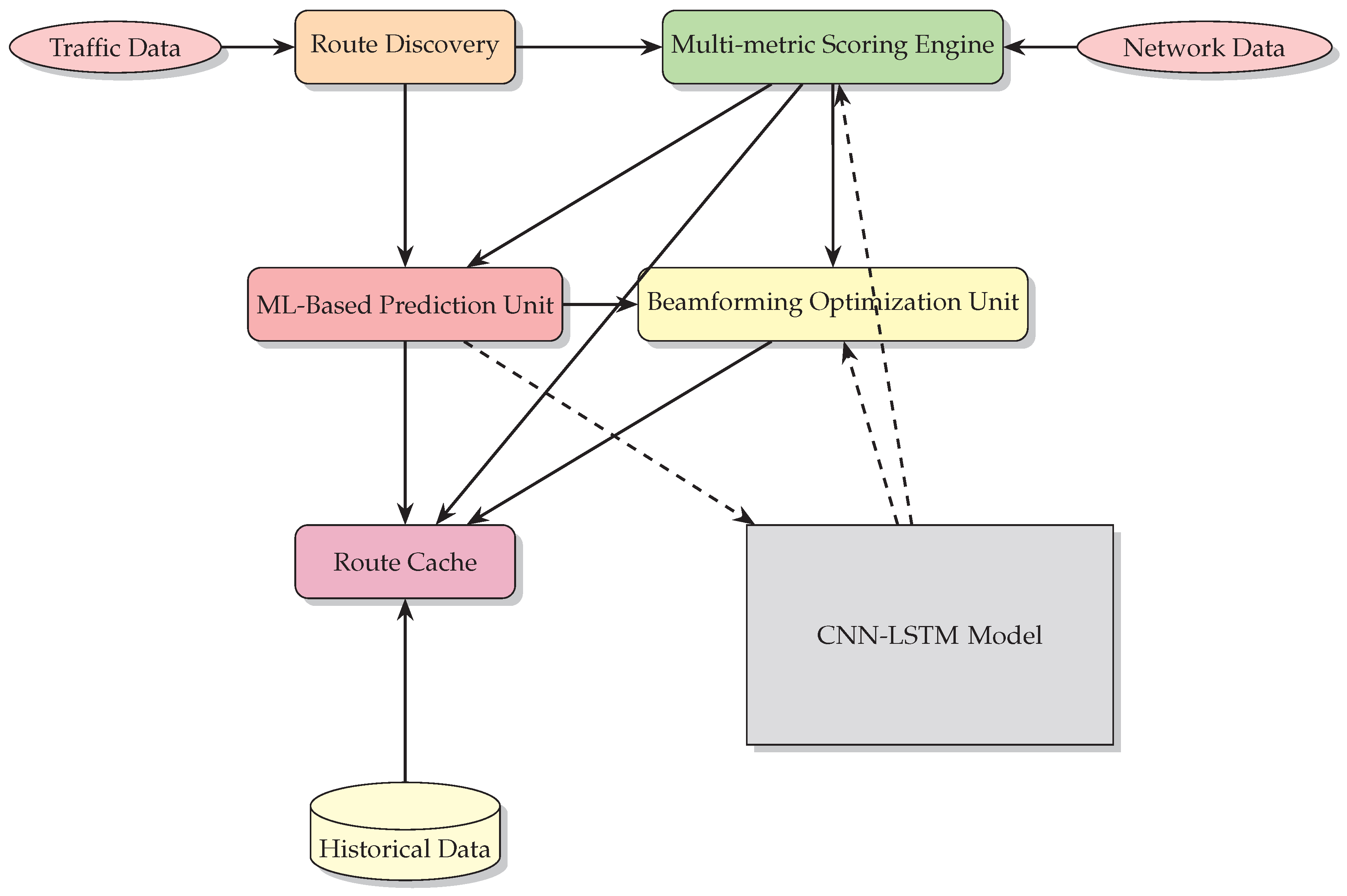
MMS-DSR’s architecture is designed to optimize routing decisions dynamically in 6G MANETs by integrating advanced machine learning models and beamforming techniques, specifically tailored for the dynamic and complex environments of smart cities. This protocol builds upon a modular structure that enhances traditional DSR components with modern technological advancements to improve adaptability and performance. Below is a detailed breakdown of each component within this architecture:
  • Route Discovery Unit (RDU): initiates the discovery process when a route to a destination is required. Using a combination of traditional flooding methods and predictive models, it efficiently identifies potential routes. In smart cities, this process is further enhanced by using machine learning to predict and avoid congested or unreliable paths. This proactive route discovery is essential for maintaining high communication efficiency in urban settings.
  • Multi-metric Scoring Engine (MMSE): evaluates discovered routes based on multiple metrics such as latency, bandwidth, reliability, and beamforming efficacy. This engine uses dynamic weighting to adjust the importance of each metric based on current network conditions, which is crucial for adapting to the varying demands of urban environments.
    Beamforming Efficacy (BE): calculates the improvement in signal quality and directionality due to beamforming optimizations.
    Weighted Scoring: each metric is assigned a dynamic weight. These weights are adjusted in real-time using feedback from the Machine Learning-Based Prediction Unit to ensure that scoring aligns with the predicted network state.
    Optimization: the engine uses a combination of heuristic and machine learning techniques to fine-tune the weights based on ongoing network performance data. This adaptive approach ensures that the engine remains responsive to changing network dynamics, particularly in adjusting beamforming strategies for optimal route performance in smart cities.
  • Machine Learning-Based Prediction Unit (MLPU): utilizes CNN-LSTM models to predict future network states, including changes in channel quality and node mobility. This unit enhances route selection by forecasting future performance and optimizing beamforming directions to maintain high-quality communication links. This is particularly valuable in smart cities where predictive capabilities can lead to more proactive and efficient network management.
    Predictive Modeling: the unit employs CNN-LSTM models to analyze historical and current network data to forecast future conditions such as node mobility, channel quality, and potential interference sources.
    Integration with Beamforming: the predictions include recommended adjustments to beamforming vectors. By predicting how channel conditions will evolve, the unit guides the Beamforming Optimization Unit to adjust angles and power levels proactively.
    Feedback Loop: predictive insights are fed back into both the Route Discovery and Multi-metric Scoring Engine, allowing these modules to prioritize routes that are expected to offer the best performance in the near future.
  • Beamforming Optimization Unit (BOU): a crucial enhancement in MMS-DSR, this unit dynamically adjusts beamforming vectors using the CNN-LSTM model based on real-time and historical channel state information (CSI). This approach ensures optimal signal directionality and strength, significantly improving link reliability and throughput, which is essential for maintaining robust communication in the high-density urban scenarios of smart cities.
    Dynamic Beamforming Vector Adjustment: this unit uses the output from the Machine Learning-Based Prediction Unit to adjust beamforming vectors. It optimizes these vectors to maximize signal strength and minimize interference, considering both the current and predicted channel state information (CSI).
    Feedback to Scoring Engine: adjustments made by this unit are fed back into the Multi-metric Scoring Engine, allowing it to re-evaluate route scores with updated beamforming information.
  • Route Cache (RC): stores the most efficient routes as determined by the scoring engine. It is periodically updated based on predictive feedback from the Machine Learning-Based Prediction Unit, which now also includes beamforming vector adjustments. This adaptive caching is key in smart cities for reducing routing overhead and improving responsiveness.
    Dynamic Caching: the Route Cache dynamically stores routes that are scored highest by the Multi-metric Scoring Engine. It takes into account not only the traditional route metrics but also the beamforming efficacy, ensuring that the stored routes are optimal under current and predicted network conditions.
    Predictive Updates: based on feedback from the Machine Learning-Based Prediction Unit, the Route Cache updates its entries to preempt potential degradations in route quality. This includes adjusting stored routes based on predicted changes in node mobility and channel quality.
    Beamforming Information: each route in the cache includes detailed beamforming vector information for every link in the path.
    Support for Fast Route Recovery: in case of rapid topology changes, which are common in urban environments, the Route Cache supports fast route recovery by providing alternative paths that can be quickly evaluated and deployed.
The architectural diagram of MMS-DSR presented in Figure 2 provides a comprehensive visual representation of the various components and their interactions. The diagram is designed to reflect the complexity and integrative nature of the MMS-DSR protocol, particularly in the context of smart city environments. The Route Discovery unit, represented as an orange block, initiates the process by identifying potential routes using a blend of traditional flooding methods and predictive models. This ensures the discovered routes are both extensive and efficient, adapting dynamically to urban traffic conditions.
Following route discovery, the Multi-metric Scoring Engine, depicted as a green block, evaluates each identified route based on multiple metrics, dynamically adjusting the weight of each metric to reflect the current network conditions. This ensures that the selected routes optimize latency, bandwidth, reliability, and beamforming efficacy, providing a balanced and efficient routing solution.
The Machine Learning-Based Prediction Unit, shown as a red block, employs advanced CNN-LSTM models to predict future network states, which is crucial for proactive route adjustments. This unit forecasts changes in channel quality and node mobility, ensuring that the network adapts to future conditions rather than merely reacting to current states.
The Beamforming Optimization Unit, represented by a yellow block, plays a critical role in maintaining high-quality communication links, especially in high-density urban scenarios. By dynamically adjusting beamforming vectors based on real-time and historical channel state information (CSI), it ensures optimal signal directionality and strength, thereby enhancing link reliability and throughput.
Lastly, the Route Cache, shown as a purple block, is essential for reducing routing overhead. This component stores the most efficient routes as determined by the scoring engine and periodically updates them based on predictive feedback. The inclusion of beamforming vector adjustments further enhances the cache’s adaptability and responsiveness.
The arrows indicate the flow of information between these components, highlighting the modular and interdependent nature of the MMS-DSR architecture. Each component plays a specific role but works in concert with the others to provide a robust and adaptive routing protocol tailored for the complex environments of smart cities. The background colors enhance clarity, indicating the distinct yet interconnected roles of each component within the architecture.

4.1. Multi-Metric Scoring Engine in MMS-DSR

The Multi-metric Scoring Engine is the core component that evaluates and ranks the discovered routes based on multiple performance metrics. This engine has been significantly enhanced to consider beamforming efficacy alongside traditional metrics like latency, bandwidth, and reliability, crucial for adaptive and intelligent routing in smart cities. Here’s an in-depth look at how this engine operates within the MMS-DSR framework:
  • Dynamic Metric Evaluation: the engine processes each route to compute scores based on four key metrics:
    Latency (L): measures the total delay along the route, critical for time-sensitive applications in urban settings.
    Bandwidth (B): assesses the minimum bandwidth available on the route, important for high-data-rate applications in smart cities.
    Reliability (R): estimates the likelihood of successful packet delivery, a vital metric for ensuring communication reliability in dynamic urban environments.
    Beamforming Efficacy (BE): calculates the improvement in signal quality and directionality due to beamforming optimizations, enhancing link stability and throughput.
  • Weighted Scoring: each metric is assigned a dynamic weight reflecting its current importance based on network conditions. These weights are adjusted in real-time using feedback from the Machine Learning-Based Prediction Unit to ensure that scoring aligns with the predicted network state. This approach allows the system to adapt to the urban dynamics effectively, prioritizing different metrics as the urban environment evolves.
  • Score Computation: the overall score for each route, S, is computed as:
    S ( r o u t e ) = w 1 · 1 L ( r o u t e ) + w 2 · B ( r o u t e ) + w 3 · R ( r o u t e ) + w 4 · B E ( r o u t e )
    where w 1 , w 2 , w 3 , and w 4 are the weights for latency, bandwidth, reliability, and beamforming efficacy, respectively. This formula ensures that routes are evaluated comprehensively, incorporating both traditional and advanced metrics to select the most efficient path.
  • Optimization: the engine uses a combination of heuristic and machine learning techniques to fine-tune the weights based on ongoing network performance data. This adaptive approach ensures that the engine remains responsive to changing network dynamics, particularly in adjusting beamforming strategies for optimal route performance in smart cities.
This scoring process enables MMS-DSR to select the most efficient and reliable routes, considering both current network metrics and future state predictions. The inclusion of beamforming efficacy as a metric ensures that the protocol can adaptively manage and utilize advanced beamforming techniques in 6G networks for enhanced communication quality.

4.2. Machine Learning-Based Prediction Unit in MMS-DSR

The Machine Learning-Based Prediction Unit in MMS-DSR utilizes advanced CNN-LSTM models to predict future network states, enabling proactive adjustments to routing and beamforming parameters. This predictive capability aims to maintain high performance in the dynamic environments typical of 6G networks and smart cities.
  • Predictive Modeling: the unit employs CNN-LSTM models to analyze historical and current network data to forecast future conditions such as node mobility, channel quality, and potential interference sources. This analysis helps predict the stability and performance of each link in a route, which is crucial for smart cities where conditions change rapidly.
  • Integration with Beamforming: the predictions include recommended adjustments to beamforming vectors to optimize communication links for future network states. By predicting how channel conditions will evolve, the unit guides the Beamforming Optimization Unit to adjust angles and power levels proactively, ensuring optimal performance in the varied urban topography and infrastructure.
  • Feedback Loop: predictive insights are fed back into both the Route Discovery and Multi-metric Scoring Engine, allowing these modules to prioritize routes that are expected to offer the best performance in the near future. This feedback loop ensures that routing decisions are made with an eye towards future conditions, not just current metrics, enhancing the adaptability and foresight of the routing protocol in smart cities.
  • Model Training and Updating: the CNN-LSTM models are continuously trained and updated with new data to improve their accuracy. This ongoing training process allows the models to adapt to changes in network behavior and topology, ensuring that the predictions remain relevant and accurate over time. This continual learning is essential in smart cities, where urban conditions and patterns can evolve unpredictably.
The use of machine learning for predictive analysis significantly enhances the adaptability of MMS-DSR, enabling it to handle the complexities of 6G network environments effectively. By forecasting future network states and adjusting routing and beamforming accordingly, this unit helps maintain optimal communication quality and reliability.

4.3. Beamforming Optimization Unit in MMS-DSR

The Beamforming Optimization Unit is a key enhancement in MMS-DSR, designed to dynamically optimize beamforming vectors using CNN-LSTM models based on the predicted network conditions. This unit plays a critical role in adjusting the beamforming strategies to enhance signal quality and reliability over time, particularly in urban scenarios where buildings and other structures can cause significant signal reflection and diffraction.
  • Dynamic Beamforming Vector Adjustment: this unit uses the output from the Machine Learning-Based Prediction Unit to adjust beamforming vectors. It optimizes these vectors to maximize signal strength and minimize interference, considering both the current and predicted channel state information (CSI). This real-time adjustment is crucial for urban environments where obstacles may deflect or block signals unexpectedly.
  • CNN-LSTM Based Predictions: the unit employs Convolutional Neural Networks (CNNs) combined with Long Short-Term Memory networks to analyze spatial and temporal aspects of the network. This model predicts optimal beamforming directions and power levels for each node in the network.
  • Real-Time Optimization: beamforming vectors are adjusted in real-time based on the predictive analytics. This ensures that each node can proactively adapt to changing network conditions, maintaining high-quality communication links, which is essential in smart cities for supporting uninterrupted service delivery.
  • Feedback to Scoring Engine: adjustments made by this unit are fed back into the Multi-metric Scoring Engine, allowing it to re-evaluate route scores with updated beamforming information. This feedback loop ensures that routing decisions remain optimal as network conditions evolve, particularly under the variable urban dynamics.
  • Integration with Routing: information about the optimized beamforming vectors is included in the route discovery and maintenance processes, ensuring that all nodes along a chosen route adjust their beamforming strategies cohesively for uniform signal enhancement across the urban network.
By dynamically optimizing beamforming vectors, this unit significantly contributes to the robustness and efficiency of MMS-DSR, particularly in environments where directional communication can greatly enhance performance, such as in crowded urban areas.
Algorithm 1: Beamforming Vector Optimization Algorithm
1:
procedureOptimizeBeamformingVectors(Routes, CNNLSTMModel)  
2:
    for each Route in Routes do  
3:
        for each Link in Route do  
4:
           LinkCSI ← GetCurrentCSI(Link)  
5:
           PredictedCSI ← CNNLSTMModel.Predict(LinkCSI)  
6:
           OptimalVectors ← CalculateOptimalBeamformingVectors(PredictedCSI)  
7:
           AdjustBeamformingVectors(Link, OptimalVectors)  
8:
        end for  
9:
    end for  
10:
end procedure

4.4. Route Cache in MMS-DSR

The Route Cache in MMS-DSR has been enhanced to dynamically store and manage the most efficient routes based on real-time and predictive analytics. This module now works closely with the Beamforming Optimization Unit to ensure that the cached routes are not only optimal in terms of path metrics but also in terms of communication quality and reliability.
  • Dynamic Caching: the Route Cache dynamically stores routes that are scored highest by the Multi-metric Scoring Engine. It takes into account not only the traditional route metrics but also the beamforming efficacy, ensuring that the stored routes are optimal under current and predicted network conditions. This dynamic caching is key for reducing routing overhead and improving responsiveness in the fluctuating urban environment.
  • Predictive Updates: based on feedback from the Machine Learning-Based Prediction Unit, the Route Cache updates its entries to preempt potential degradations in route quality. This includes adjusting stored routes based on predicted changes in node mobility and channel quality, ensuring that the cache reflects the most current and anticipated network states, enhancing the system’s ability to handle urban dynamics.
  • Beamforming Information: each route in the cache includes detailed beamforming vector information for every link in the path. This ensures that when a route is retrieved from the cache, each node along the path can quickly adjust its beamforming vectors to the optimal settings, facilitating a coherent and coordinated approach to maintaining route quality.
  • Eviction and Maintenance: the cache follows an intelligent eviction policy where less optimal routes are replaced by newer, higher-quality routes. This policy considers route age, frequency of use, and predictive quality scores to maintain a balance between route freshness and historical efficacy, which is crucial for ensuring that the network can quickly adapt to changes in the urban context.
  • Support for Fast Route Recovery: in case of rapid topology changes, which are common in urban environments, the Route Cache supports fast route recovery by providing alternative paths that can be quickly evaluated and deployed, minimizing downtime and packet loss.
The enhancements to the Route Cache enable MMS-DSR to maintain a high-performance routing table that is adaptive and predictive, significantly reducing the need for frequent route discoveries and improving overall network efficiency in the complex and dynamic environments of smart cities.
Algorithm 2: Dynamic Route Caching and Maintenance Algorithm
1:
procedureUpdateRouteCache(NewRoute, PredictedQuality)  
2:
    if RouteCache.IsFull() then  
3:
        EvictLeastOptimalRoute(RouteCache)  
4:
    end if  
5:
    AdjustBeamformingVectors(NewRoute)  
6:
    RouteCache.Store(NewRoute, PredictedQuality)  
7:
end procedure

4.5. Mathematical Formalization

MMS-DSR is designed with a unique multi-metric scoring function that adapts in real-time to the dynamic nature of Mobile Ad-Hoc Networks, incorporating beamforming strategies to enhance signal quality and reliability. This scoring function serves as the backbone for making robust and efficient routing decisions, especially in the complex and rapidly changing environments of smart cities. The scoring function S ( r , t ) in MMS-DSR is defined as:
S ( r , t ) = α · i = 1 n w i ( t ) · m i ( r ) + δ · P prediction ( r , t ) + λ · B F ( r , t )
where m i ( r ) are the route metrics, w i ( t ) the time-dependent weights, α a weighting factor for the summation real-time term, δ a factor integrating the predictive reliability score P p r e d i c t i o n ( r , t ) , and λ a weighting factor for the beamforming score B F ( r , t ) .
The weights w i ( t ) are dynamically adjusted based on real-time network analytics and predictions from the Machine Learning-Based Prediction Unit to reflect the changing urban conditions. This adjustment is given by:
w i ( t + 1 ) = w i ( t ) η J ( w , t ) w i ( t )
where η is the learning rate and J ( w , t ) w i ( t ) is the gradient of the cost function with respect to weight w i ( t ) .
The cost function J ( w , t ) is designed to minimize the difference between the current metric values and their predicted values, ensuring that the weights reflect the most relevant network conditions. The cost function is defined as:
J ( w , t ) = i = 1 n m i ( r , t ) m ^ i ( r , t ) m ^ i ( r , t ) 2
where m i ( r , t ) is the network metric for route r at time t, and m ^ i ( r , t ) is the predicted value of the metric provided by the Machine Learning-Based Prediction Unit.
In order to understand how the parameters P p r e d i c t i o n ( r , t ) and B F ( r , t ) are obtained we must talk about Hybrid CNN-LSTM models. Hybrid Deep Learning models combining CNN and LSTM can improve the prediction accuracy [46,47,48,49]. The spatial and temporal features can be thoroughly extracted using hybrid models, where CNN is utilized to capture the spatial features of traffic data, while LSTM is employed to extract the temporal features. Let’s consider that we have traffic state data of K locations s i ( i = 1 , 2 , , K ) as inputs to predict the traffic states at times t , t + 1 , , t + h . The real-time measured data can be arranged, as explained in [49,50,51], into a matrix:
S = s 1 s 2 s K = s 1 , t N s 1 , t N + 1 s 1 , t 1 s 2 , t N s 2 , t N + 1 s 2 , t 1 s K , t N s K , t N + 1 s K , t 1
In P p r e d i c t i o n ( r , t ) , the element s k , t in the matrix is a vector which includes latency L, bandwidth B, reliability R, and beamforming efficacy B E . In B F ( r , t ) , the element s k , t in the matrix is a vector that contains the channel state information (CSI). The real-time measured data matrix S is first parallelized in the time domain and then input into the CNN, which captures high-level spatial features. Finally, the high-level spatial feature map is fed into LSTM models to generate the final prediction.
The high-level spatial feature map output by the CNN can be expressed as:
X = x 1 x 2 x L = x 1 , t N x 1 , t N + 1 x 1 , t 1 x 2 , t N x 2 , t N + 1 x 2 , t 1 x L , t N x L , t N + 1 x L , t 1
where: X is the high-level spatial feature map, x l , t is the l-th high-level feature at the t-th time instant, L is the number of high-level features, and N is the length of the time window considered.
Each feature x l , t is obtained using the following equation:
x l , t = f l ( w t S t + b t )
where: w t is the filter with K L + 1 coefficients, S t is the t-th column of S , b t is the bias term, f l is the l-th activation function, ⊗ denotes the convolution operation.
To extract temporal features, the high-level spatial feature vector is selected as the input of LSTM, denoted as:
F = [ F 0 F 1 F N 1 ]
where F n is the high-level spatial feature map for the n-th LSTM network, represented as:
F n = x 1 , t + n N x 1 , t + n N + 1 x 1 , t + n N + M 1 x 2 , t + n N x 2 , t + n N + 1 x 2 , t + n N + M 1 x L , t + n N x L , t + n N + 1 x L , t + n N + M 1
where M is the adjustable input window size.
The spatio-temporal features output by LSTM are denoted as:
H = [ H 0 H 1 H N 1 ]
where H n is a K × T matrix, and T is the adjustable output window size with M + T N .
The generated spatio-temporal features are iteratively determined by:
f n = σ W f , F · vec ( F n ) + W f , H · vec ( H n 1 ) + b f i n = σ W i , F · vec ( F n ) + W i , H · vec ( H n 1 ) + b i c n = f n c n 1 + i n tanh W c , F · vec ( F n ) + W c , H · vec ( H n 1 ) + b c o n = σ W o , F · vec ( F n ) + W o , H · vec ( H n 1 ) + b o H n = o n tanh ( c n )
where: W * , F , W * , H are weighting matrices for current input high-level spatial feature matrix F n and previous spatio-temporal feature matrix H n 1 . vec ( · ) denotes vectorization due to different sizes of F n and H n 1 . σ and tanh are sigmoid and hyperbolic tangent functions applied element-wise.
MMS-DSR uses the infinite-horizon discounted Markov Decision Process (MDP) framework for route optimization. The MDP, as detailed in [52,53], is defined by a tuple ( S , A , P , R ) , where:
  • S is the set of states representing different network conditions, including the varying urban scenarios.
  • A is the set of actions corresponding to route selections.
  • P is the state transition probability matrix, which is particularly complex in urban environments due to the myriad of potential interactions and obstructions.
  • R is the reward function, aligned with the scoring function S ( r , t ) , and is enhanced to factor in urban dynamics and machine learning predictions.
The optimization objective in MDP, as well described in is formulated as:
π * = arg max π E t = 0 γ t R ( s t , π ( s t ) )
where π * is the optimal policy we want to find, π is a policy that maps states to actions, E is the mathematical expectation, representing the average value considering all possible sequences of states and actions, t = 0 γ t R ( s t , a t ) is the discounted sum of rewards over time, t is the time index, γ is the discount factor, R ( s t , a t ) is the reward obtained by taking action a t in state s t . The discount factor γ (0 < γ < 1) reduces the weight of future rewards. Values close to 1 give more importance to future rewards, while values close to 0 emphasize immediate rewards.
In brief, the prediction model can be represented as:
Y t = f CNN - LSTM ( X t )
where: X t is the input feature vector at time t, Y t is the predicted future state at time t, f CNN - LSTM represents the CNN-LSTM model.
This prediction is then used to adjust the beamforming vectors B F ( r , t ) and to update the multi-metric scoring engine P p r e d i c t i o n ( r , t ) . The CNN component extracts spatial features from the channel state information (CSI), while the LSTM component captures temporal dependencies, enabling the model to predict optimal beamforming strategies.
The beamforming optimization can be expressed as:
B F ( r , t ) = f opt ( C S I t , Y t )
where: C S I t is the current channel state information at time t, B F ( r , t ) is the beamforming vector at time t for route r, f opt is the optimization function.
Here, Y t is the predicted future state from the CNN-LSTM model, and f opt calculates the optimal beamforming vectors to enhance communication quality and reliability.
The optimization function typically aims to maximize signal strength and minimize interference. One way to model this is by maximizing the signal-to-interference-plus-noise ratio (SINR) for each beamforming vector. Here is a general formula for f opt :
B F ( r , t ) = arg max B F H t · B F ( r , t ) σ 2 + i t I i ( B F ( r , t ) )
where: H t represents the channel gain matrix for the current time t, B F ( r , t ) is the beamforming vector at time t, σ 2 is the noise power, I i ( B F ( r , t ) ) represents the interference from other users or sources when using the beamforming vector B F ( r , t ) . The optimization seeks to maximize the SINR by adjusting the beamforming vectors B F ( r , t ) .
The Beamforming Optimization Unit dynamically adjusts beamforming vectors to maximize signal strength and minimize interference, based on both current and predicted channel state information (CSI). This optimization ensures that each node in the network can maintain high-quality communication links, which is essential in complex urban environments.
We conclude this part by explaining the reasons why we introduced the α , δ , and λ weights. To ensure that as experience increases, the predictive terms ( P prediction ( r , t ) and B F ( r , t ) ) become more significant while the real-time term ( i = 1 n w i ( t ) · m i ( r ) ) becomes less significant, we define a regulation formula. This formula adjusts the ratio between α , δ , and λ over time or experience E:
α δ + λ = f ( E )
where f ( E ) is a decreasing function of experience. A possible choice for f ( E ) could be an exponential decay function:
f ( E ) = e β E
where β is a constant that controls the rate of decay. Thus, the relationship becomes:
α δ + λ = e β E
As experience E increases, e β E decreases, indicating that α should decrease relative to δ and λ . This ensures the predictive terms gain more importance over time.
To summarize, the final formulation of the scoring function S ( r , t ) with the regulation formula is:
S ( r , t ) = α ( E ) · i = 1 n w i ( t ) · m i ( r ) + δ · P prediction ( r , t ) + λ · B F ( r , t )
where
α ( E ) = ( δ + λ ) · e β E
This adjustment ensures that the real-time metrics i = 1 n w i ( t ) · m i ( r ) become less influential as the system gains more experience, while the predictive metrics P prediction ( r , t ) and B F ( r , t ) become more influential.

4.5.1. Proof of Effectiveness through Simulation and Analysis

The effectiveness of MMS-DSR is substantiated through:
  • Simulation studies that demonstrate rapid convergence, adaptability, and efficiency, particularly in urban settings where the network topology and conditions can change unpredictably.
  • Comparative analysis with existing protocols, showcasing superior performance in varied network conditions, with a focus on urban environments where traditional protocols often fail to maintain high performance.
  • Statistical analysis of network performance metrics such as latency, throughput, reliability, and beamforming efficacy over multiple simulation runs, illustrating significant improvements in smart city applications.

4.5.2. Numerical Illustration

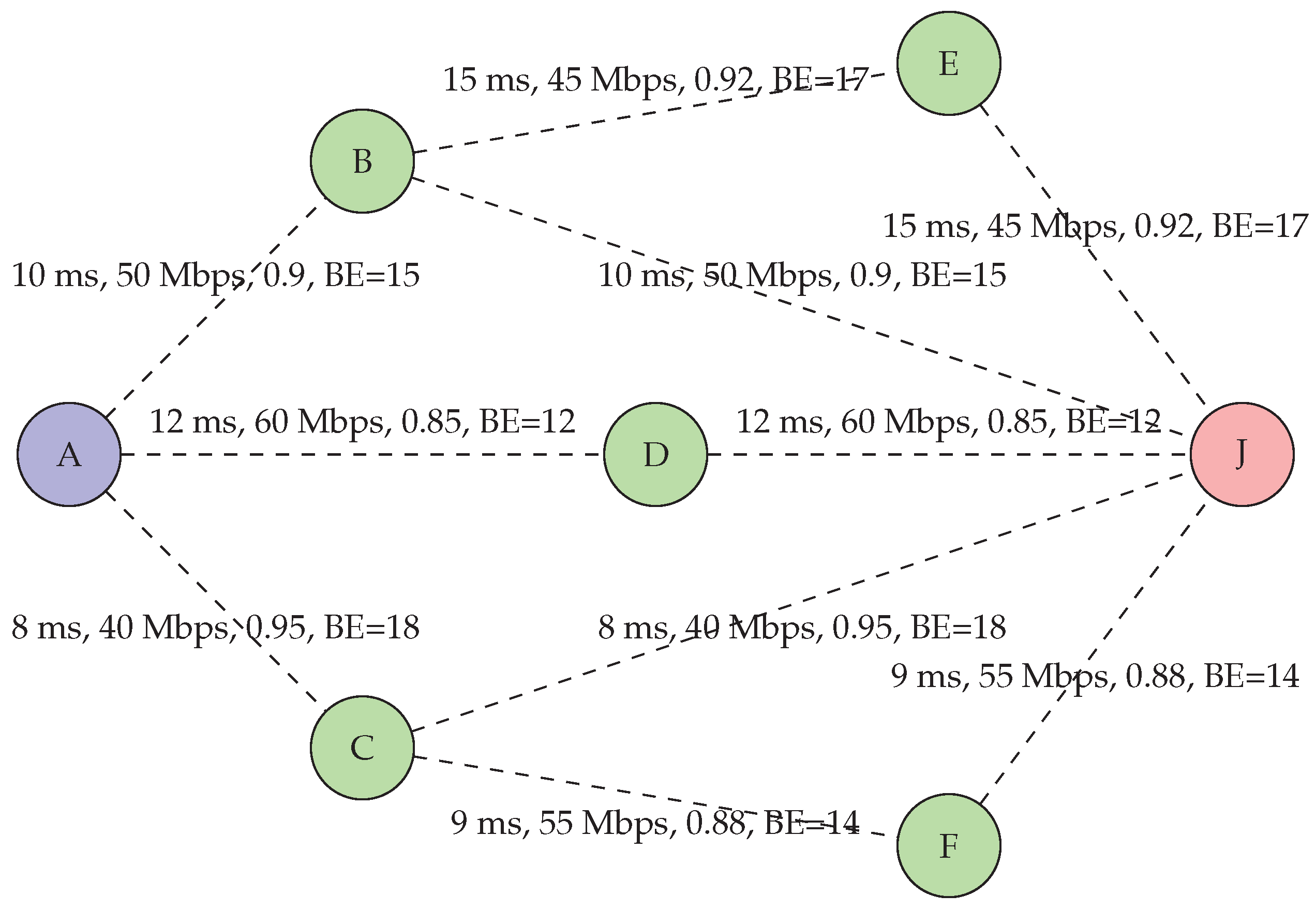
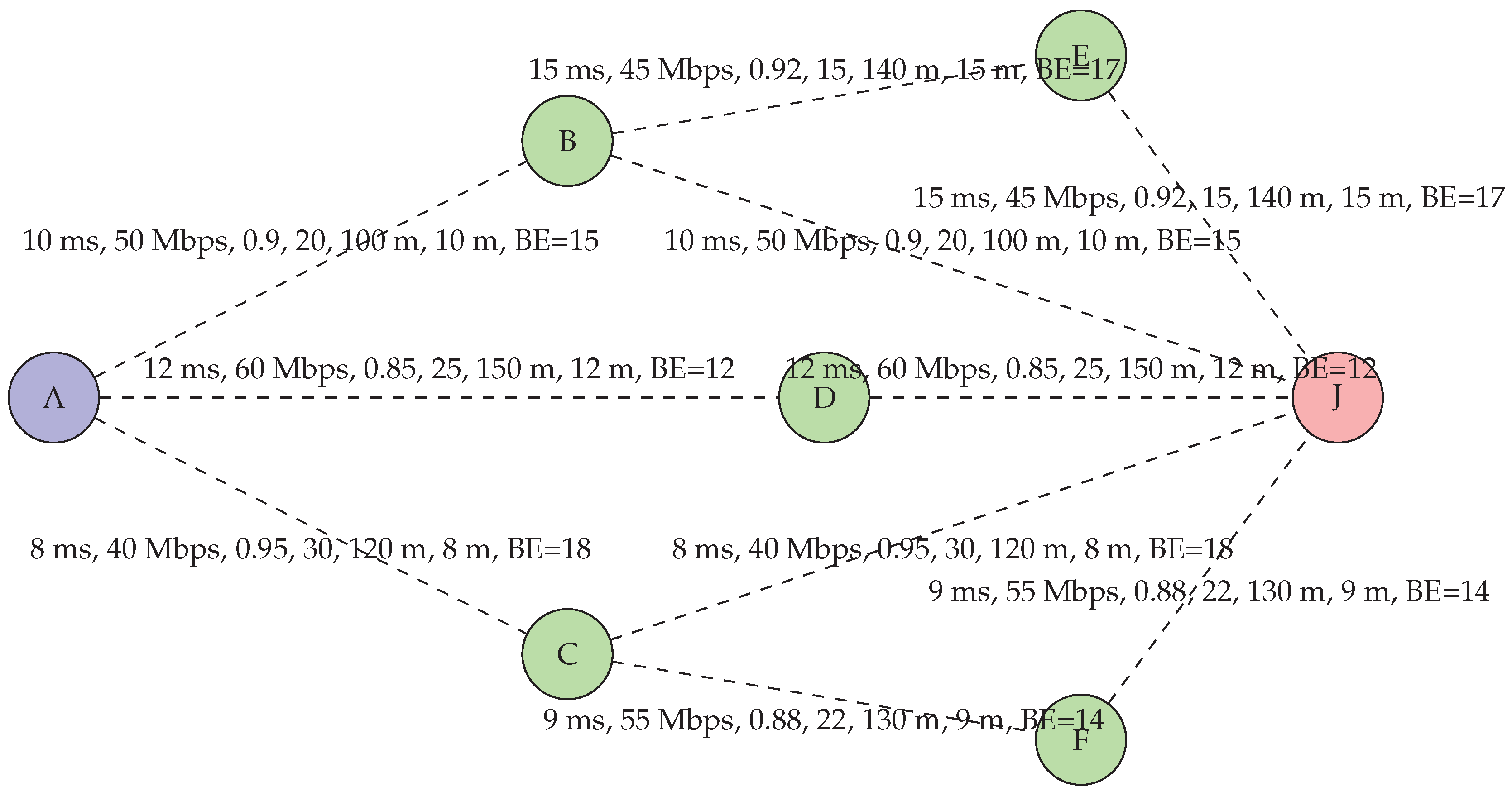
To provide a concrete understanding of the MMS-DSR scoring mechanism, we present a numerical example with a network topology, as illustrated in Figure 3. This hypothetical scenario considers several candidate routes, each with different metrics for latency, bandwidth, reliability, and beamforming efficacy (BE), typical of diverse urban paths.
The routes and their respective metrics are summarized in Table 1.
Table 2. Example routes with associated metrics.
Route Latency (ms) Bandwidth (Mbps) Reliability Beamforming Efficacy (BE)
r 1 10 50 0.9 15
r 2 8 40 0.95 18
r 3 12 60 0.85 12
r 4 15 45 0.92 17
r 5 9 55 0.88 14
r 6 10 50 0.9 15
r 7 8 40 0.95 18
r 8 12 60 0.85 12
r 9 15 45 0.92 17
r 10 9 55 0.88 14
Using the scoring function we assume the following parameters: δ = 0.2 , λ = 0.3 , β = 0 , Experience E = 10 , dynamic weights at time t: w 1 ( t ) = 0.35 , w 2 ( t ) = 0.4 , w 3 ( t ) = 0.2 , w 4 ( t ) = 0.05 .
The Predictive reliability scores at time t: P p r e d i c t i o n ( r 1 , t ) = 0.92 , P p r e d i c t i o n ( r 2 , t ) = 0.87 , P p r e d i c t i o n ( r 3 , t ) = 0.90 , P p r e d i c t i o n ( r 4 , t ) = 0.91 , P p r e d i c t i o n ( r 5 , t ) = 0.89 , P p r e d i c t i o n ( r 6 , t ) = 0.92 , P p r e d i c t i o n ( r 7 , t ) = 0.87 , P p r e d i c t i o n ( r 8 , t ) = 0.90 , P p r e d i c t i o n ( r 9 , t ) = 0.91 , P p r e d i c t i o n ( r 10 , t ) = 0.90 .
The Beamforming Factor (BF) scores at time t: B F ( r 1 , t ) = 20 , B F ( r 2 , t ) = 22.5 , B F ( r 3 , t ) = 15 , B F ( r 4 , t ) = 21 , B F ( r 5 , t ) = 19 , B F ( r 6 , t ) = 20 , B F ( r 7 , t ) = 22.5 , B F ( r 8 , t ) = 20 , B F ( r 9 , t ) = 22.5 , B F ( r 10 , t ) = 15 .
To ensure fair comparison, the metrics are normalized to a [0, 1] scale using the formula:
x norm = x x min x max x min
Table 3. Normalized metrics for each route.
Route Latency Norm Bandwidth Norm Reliability Norm BE Norm
r1 0.286 0.50 0.5 0.500
r2 0.000 0.00 1.0 1.000
r3 0.571 1.00 0.0 0.000
r4 1.000 0.25 0.7 0.833
r5 0.143 0.75 0.3 0.333
r6 0.286 0.50 0.5 0.500
r7 0.000 0.00 1.0 1.000
r8 0.571 1.00 0.0 0.000
r9 1.000 0.25 0.7 0.833
r10 0.143 0.75 0.3 0.333
The Predictive reliability scores at time t were also normalized obtaining the following values: P p r e d i c t i o n N o r m ( r 1 , t ) = 1.0 , P p r e d i c t i o n N o r m ( r 2 , t ) = 0.0 , P p r e d i c t i o n N o r m ( r 3 , t ) = 0.6 , P p r e d i c t i o n N o r m ( r 4 , t ) = 0.8 , P p r e d i c t i o n N o r m ( r 5 , t ) = 0.4 , P p r e d i c t i o n N o r m ( r 6 , t ) = 1.0 , P p r e d i c t i o n N o r m ( r 7 , t ) = 0.0 , P p r e d i c t i o n N o r m ( r 8 , t ) = 0.6 , P p r e d i c t i o n N o r m ( r 9 , t ) = 0.8 , P p r e d i c t i o n N o r m ( r 10 , t ) = 0.6 .
The Beamforming Factor (BF) scores at time t were normalized obtaining the following values: B F N o r m ( r 1 , t ) = 0.667 , B F N o r m ( r 2 , t ) = 1.000 , B F N o r m ( r 3 , t ) = 0.000 , B F N o r m ( r 4 , t ) = 0.800 , B F N o r m ( r 5 , t ) = 0.533 , B F N o r m ( r 6 , t ) = 0.667 , B F N o r m ( r 7 , t ) = 1.000 , B F N o r m ( r 8 , t ) = 0.667 , B F N o r m ( r 9 , t ) = 1.000 , B F N o r m ( r 10 , t ) = 0.000 .
The scoring function S ( r , t ) for each route is calculated using the normalized values.
For example for r 1 we have:
S ( r 1 , t ) = 0.5 × 0.35 · 0.286 + 0.4 · 0.50 + 0.2 · 0.5 + 0.05 · 0.5 + 0.2 · 1.0 + 0.3 · 0.667
S ( r 1 , t ) = 0.5 × ( 0.1001 + 0.2 + 0.1 + 0.025 ) + 0.2 + 0.2
S ( r 1 , t ) = 0.21255 + 0.2 + 0.2
S ( r 1 , t ) = 0.6125
Repeating the same calculations for each route we will obtain the following values:
Table 4. Scoring Function values for each route after normalization.
Route Scoring Function (SF)
r1 0.612500
r2 0.425000
r3 0.420000
r4 0.715833
r5 0.453333
r6 0.612500
r7 0.425000
r8 0.620000
r9 0.775833
r10 0.333333
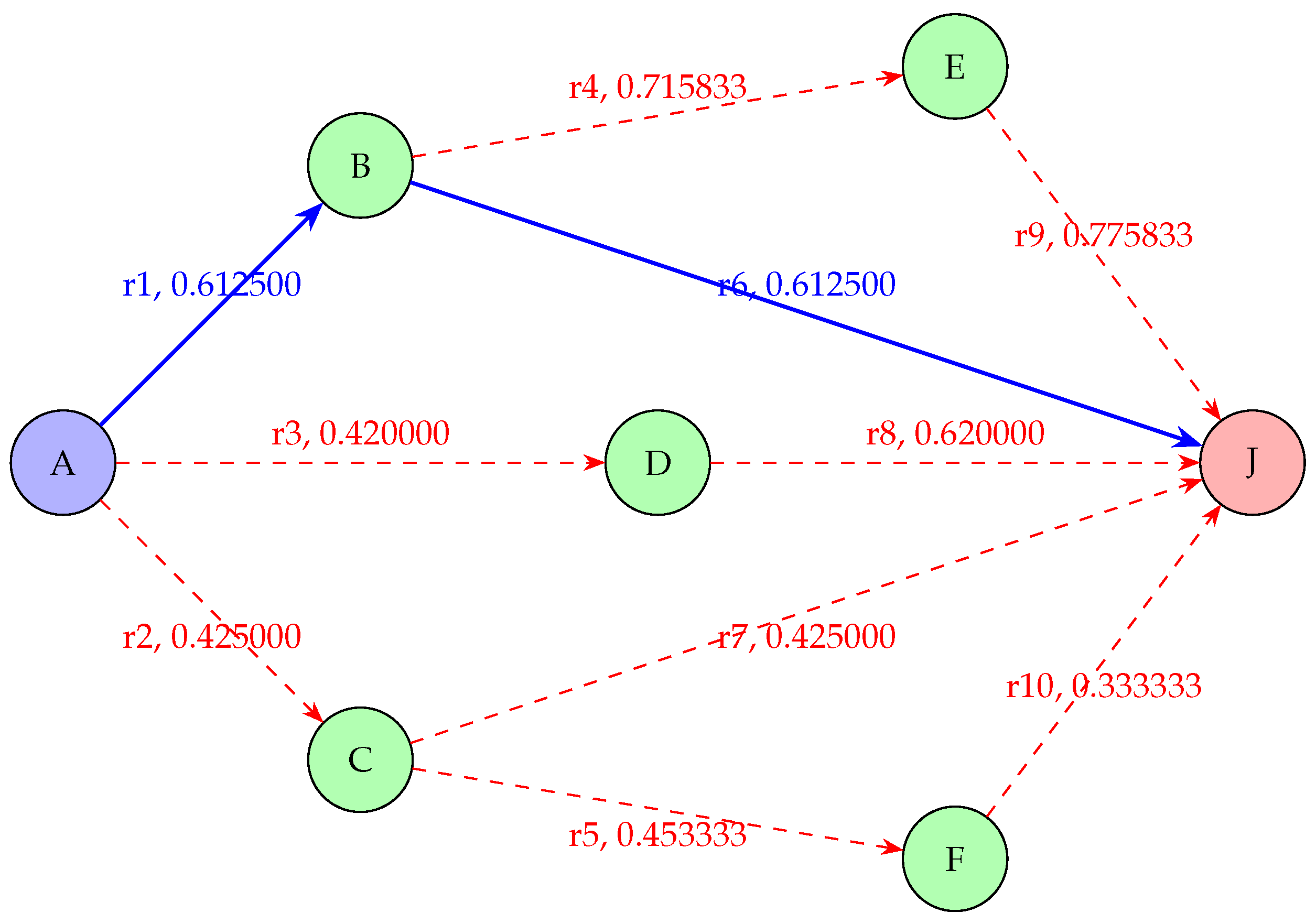
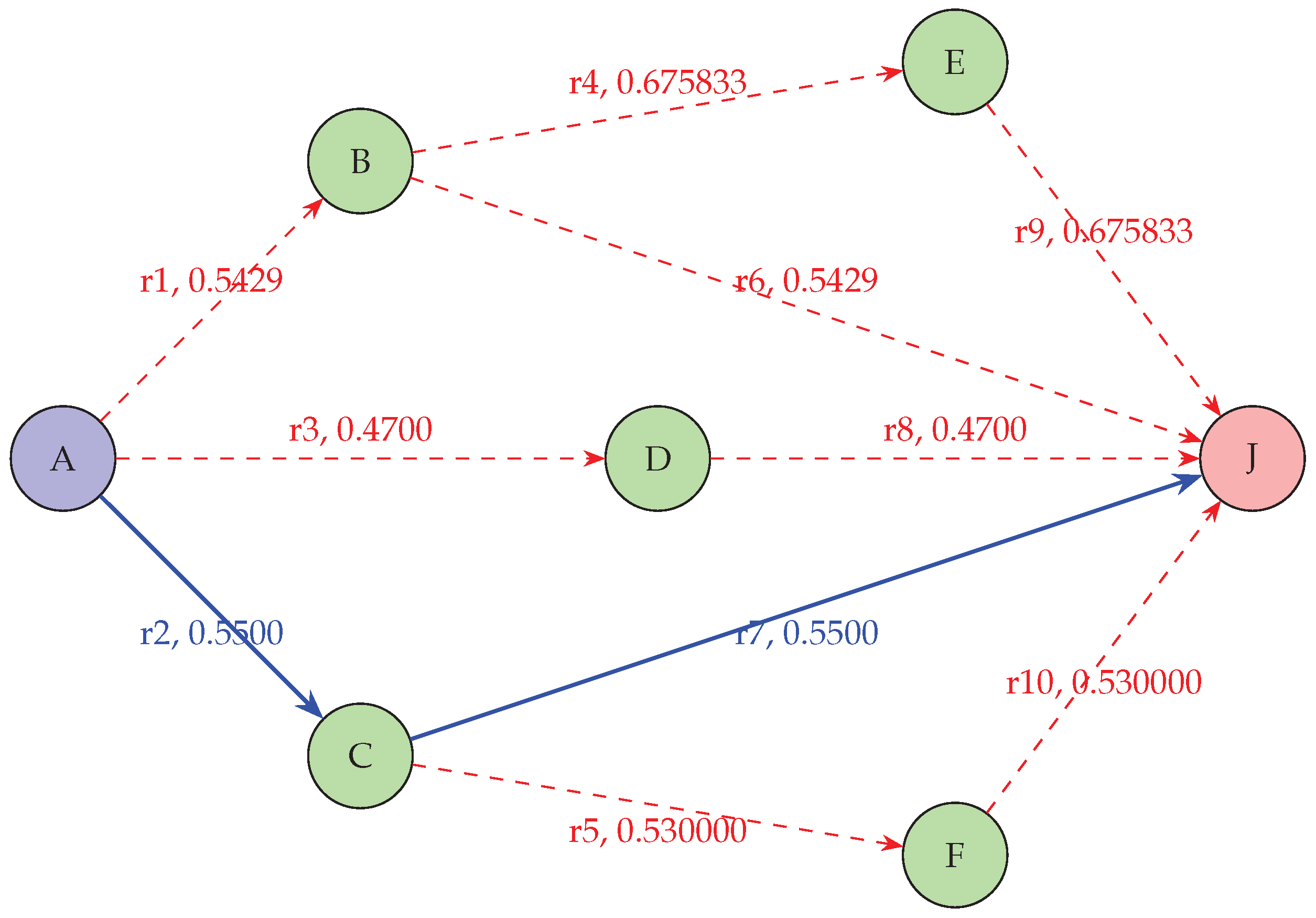
Even if by applying the scoring function, the path r 9 emerges as the optimal route with the highest score of 0.775833 , we must remember that in the classic DSR protocol, the primary metric for selecting the optimal path is typically the number of hops. Carrying out the route analysis of the graph illustrated in Figure 4, the possible paths from source to destination and the related Scoring Function (SF) values are shown in Table 5:
Table 5. Paths, Routes, and Total Scoring Functions (SF).
Path Routes Total SF
A → B → J r1 + r6 0.612500 + 0.612500 = 1.225
A → C → J r2 + r7 0.425000 + 0.425000 = 0.850
A → D → J r3 + r8 0.420000 + 0.620000 = 1.040
A → B → E → J r1 + r4 + r9 0.612500 + 0.715833 + 0.775833 = 2.104166
A → C → F → J r2 + r5 + r10 0.425000 + 0.453333 + 0.333333 = 1.211666
Considering that MMS-DSR prioritizes the route with the highest cumulative scoring function (SF) and minimum number of hops, the chosen optimal path would be:
A > B > J with a total S F of 1.225 .
In conclusion this numerical illustration demonstrates the effectiveness of MMS-DSR’s scoring engine and shows how it can determine the optimal path in a network topology, considering various metrics and beamforming efficacy.

5. CNN-LSTM Model Architecture

The CNN-LSTM model in MMS-DSR represents a sophisticated hybrid approach designed to analyze and process both spatial and temporal data, making it exceptionally suitable for dynamic urban network environments. Here’s a step-by-step breakdown of the model architecture and its integration into the routing protocol:
  • Input Data Preparation: network data including historical latency (L), bandwidth (B), reliability (R), and beamforming efficacy ( B E ) or channel state information ( C S I ) are collected. This data, reflecting both current and past network states, forms the basis for the input features that feed into the CNN-LSTM model.
  • Spatial Feature Extraction with CNN: the CNN layers first receive normalized input data. These layers are tasked with extracting spatial features from the data. Using convolutional filters, the model processes input vectors like L ^ , B ^ , R ^ , and B E ^ , or C S I ^ converting them into comprehensive feature maps. These maps identify critical spatial patterns, such as congestion points or optimal paths, crucial for effective route planning in densely populated urban areas.
  • Temporal Pattern Analysis with LSTM: the feature maps generated by the CNN are then fed into LSTM layers. The LSTM, with its ability to process data sequentially, examines these features over time. It detects temporal dependencies and dynamics, such as evolving traffic patterns or changes in network topology, which are essential for predicting future network states and behaviors.
  • Integration of CNN and LSTM Outputs: the integration stage amalgamates the spatial insights from the CNN with the temporal predictions of the LSTM. This combined data forms a robust set of predictive insights that forecast future route conditions, enabling proactive adjustments to routing and beamforming strategies.
  • Route Optimization Outputs: utilizing the predictive insights, the model outputs recommendations for route adjustments and beamforming optimizations. These recommendations are designed to enhance route reliability and communication efficiency, particularly in scenarios with high mobility and variable network conditions.
  • Model Training and Real-time Deployment: the CNN-LSTM model is initially trained offline using a diverse set of simulated network scenarios, which include varied urban traffic patterns and node configurations. Once trained, the model is integrated into the MMS-DSR protocol running within the network simulation environment, where it operates in real-time to continuously refine routing decisions based on its predictions.
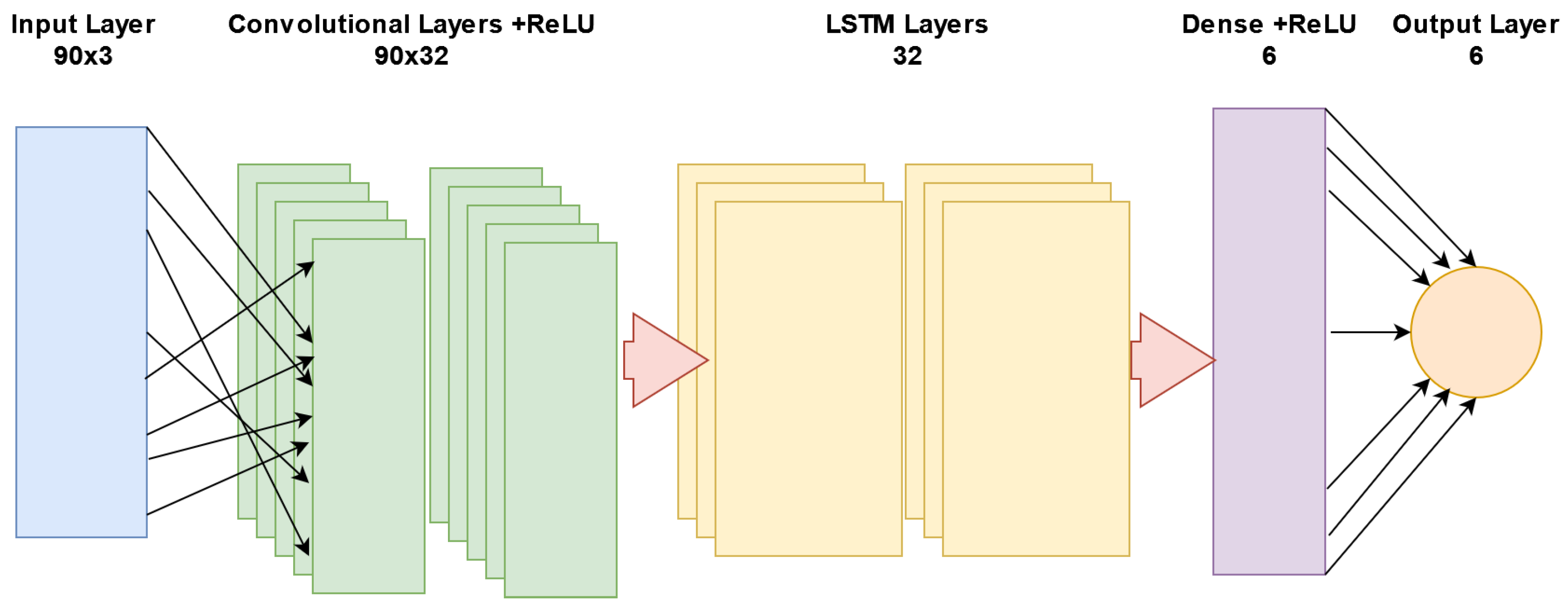
The CNN-LSTM model diagram provided in Figure 5 illustrates the model architecture tailored specifically for the MMS-DSR system, which is designed to enhance route optimization and beamforming. This architecture is meticulously crafted to interpret both spatial and temporal data, thereby providing a robust framework that supports real-time, dynamic decision-making in smart city applications. Here is a detailed breakdown of how each component of the CNN-LSTM model contributes to the prediction and management of network routing and communication strategies.
The model begins with an input layer that handles raw data dimensions of 90 × 3 . This layer is responsible for receiving diverse network metrics such as latency, bandwidth, and reliability over time. The structured format allows the model to uniformly process data across different network conditions, ensuring that all relevant spatial and temporal features are captured from the outset.
Following the input, the data passes through two convolutional layers, each employing Rectified Linear Unit (ReLU) activation functions. These layers are used for extracting spatial features from the network data. By applying multiple filters, the convolutional layers produce feature maps ( 90 × 32 ) that identify critical spatial patterns such as areas with high node density or potential signal interference caused by urban infrastructure. These spatial insights are essential for assessing the current state of the network and anticipating areas that might require special attention for routing. The spatially processed data is then forwarded to two LSTM layers, which are crucial for understanding temporal dynamics. These layers, by maintaining a state that reflects historical data, can capture time-dependent patterns such as periodic increases in traffic flow or the typical mobility paths of nodes within the network. Each LSTM layer outputs 32 features, which collectively provide a deep temporal analysis essential for predicting future network states. The process culminates in a dense layer followed by an output layer with softmax activation.
The input dimension of 90 × 3 was selected based on the typical range of network metrics collected per minute over a window of 30 minutes. This ensures that the model captures sufficient temporal depth to assess trends and anomalies effectively. Two convolutional layers with 32 filters each were chosen to balance computational efficiency with the ability to capture complex spatial relationships within the data. The size of the filters was determined by the scale of spatial patterns typically observed in urban vehicular networks. Two LSTM layers with 32 units each provide the necessary capacity to track long-term dependencies in traffic flow and network performance, crucial for predicting future states in a dynamic setting. The six units in the dense output layer correspond to the number of possible route adjustments and beamforming strategies that the system can recommend, covering typical traffic scenarios encountered in urban environments.
The dense layer consolidates the temporal data into six comprehensive features, which are then classified by the softmax layer to predict the most probable next states of the network. This output can directly influence decision-making in the network, providing predictions on route stability, optimal paths, and necessary beamforming adjustments. The CNN-LSTM model’s predictions are integral to the MMS-DSR protocol, enhancing its capability to dynamically adjust routes and communication strategies. By predicting route stability and optimal beamforming vectors, the model enables MMS-DSR to proactively adjust to anticipated changes in the network environment. This predictive capability is crucial for maintaining robust communication links in urban settings, where obstacles and variable node speeds can abruptly alter network dynamics. In practical terms, when an emergency vehicle needs to navigate through a congested city area, the CNN-LSTM model can predict the quickest and safest routes by analyzing current and historical traffic data along with real-time communication conditions. This allows the MMS-DSR protocol to dynamically manage the vehicle’s path and communication, ensuring that critical information is relayed without delay and the vehicle reaches its destination efficiently.

5.1. Model Overview

The CNN-LSTM architecture deployed within the MMS-DSR model is designed to decode the complex spatial and temporal data dynamics inherent in urban network environments. This detailed explanation focuses on the individual roles and synergies of each component in the model.

5.1.1. Input Data Preparation

The model begins by assembling network performance data into a structured 3-dimensional input tensor with dimensions 90 × 3 . Each tensor slice represents one minute of data collection, capturing metrics such as latency (L), bandwidth (B), reliability (R), and beamforming efficacy ( B E ) or channel state information ( C S I ). This high-resolution temporal input is crucial for identifying immediate and emerging network conditions, ensuring the model has a comprehensive baseline for analysis.

5.1.2. Spatial Feature Extraction with CNN

The convolutional layers process the input tensor through 32 filters designed to extract nuanced spatial features from the data. This phase transforms the initial 90 × 3 tensor into detailed spatial feature maps of dimensions 90 × 32 . These maps are instrumental in pinpointing specific network characteristics, such as areas of potential congestion or signal interference, which are critical for route optimization and network management.

5.1.3. Temporal Pattern Analysis with LSTM

The spatially processed data is then advanced to the LSTM layers, where temporal analysis occurs. The LSTM layers, each featuring 32 units, scrutinize the spatial features over time, identifying temporal trends and dependencies that are significant for predicting the network’s future states. This step is essential for understanding how network conditions evolve and for making informed predictions about future network performance.

5.1.4. Integration of CNN and LSTM Outputs

This stage integrates the spatial and temporal data to form a unified predictive model. By combining the detailed spatial analysis from the CNN layers with the dynamic temporal insights from the LSTM layers, the model synthesizes a powerful predictive tool that offers a holistic view of the network’s potential future states, enhancing the accuracy and relevance of its predictions.

5.1.5. Route Optimization Outputs

The final output layer of the model uses the integrated CNN-LSTM data to generate recommendations for optimal routing and beamforming strategies. This component is particularly crucial in urban environments where network conditions are constantly changing, requiring adaptive and timely routing decisions to maintain effective communication.

5.1.6. Model Training and Real-Time Deployment

The model is initially trained using a comprehensive dataset derived from various urban scenarios to ensure it captures a wide spectrum of traffic patterns and network behaviors. Once adequately trained, it is deployed in a real-time environment within the network, where it continuously refines its predictions and adaptations based on live operational data.

5.1.7. Numerical Example Consolidation

To illustrate the CNN-LSTM model’s application within the MMS-DSR framework during a peak urban traffic period, this numerical example simulates advanced data processing and decision-making capabilities:
  • Input Data Preparation: the model ingests a tensor representing 90 minutes of network data collected at 1-minute intervals. This tensor includes key network metrics such as 45 ms latency, 150 Mbps bandwidth, and 95% reliability, along with dynamic beamforming vectors. These vectors are crucial for adapting to the rapidly changing network conditions typical in urban environments, where variables like vehicle density and building interference can significantly impact signal quality.
  • Spatial Feature Extraction with CNN: employing 32 convolutional filters, the CNN layer processes the 90 × 3 input tensor to distill spatial features. This operation transforms the input into a 90 × 32 feature map, effectively highlighting areas of high congestion and potential signal interference—key zones where proactive network management is crucial.
  • Temporal Pattern Analysis with LSTM: subsequently, the LSTM layers take over, analyzing the spatial features to identify temporal patterns. This step is essential for forecasting future network behaviors by recognizing trends and anomalies in data over time, such as the anticipated increase in congestion due to recurring events or peak traffic hours.
  • Integration of CNN and LSTM Outputs: the spatial insights and temporal predictions are then integrated to form a comprehensive predictive model. This synthesis is important for formulating accurate, actionable insights that can anticipate and mitigate potential network degradation, especially around planned public events that could dramatically alter traffic flows and network loads.
  • Route Optimization Outputs: utilizing the integrated data, the model outputs recommendations for route adjustments. These suggestions are dynamically tailored to preemptively reroute traffic away from identified congestion points, thereby enhancing the overall efficiency of the network and reducing communication latency.
  • Model Training and Real-time Deployment: the CNN-LSTM model is initially trained on historical data encompassing a wide array of traffic scenarios but is subsequently fine-tuned in real-time within the operational network environment. This training approach ensures that the model remains highly adaptive and responsive to unexpected conditions, such as emergency road closures or sudden spikes in network demand, thereby maintaining optimal network performance continuously.
The flowchart in Figure 6 visually encapsulates the systematic data transformation process within the CNN-LSTM model as it is applied within the MMS-DSR protocol. From the initial collection of diverse network metrics to the sophisticated prediction and optimization outputs, each step is designed to enhance network responsiveness and reliability in dynamic urban environments. The detailed depiction underscores the model’s role in harnessing machine learning to tackle the complexities of modern urban network management, demonstrating a structured approach to adaptive, intelligent routing.

5.2. Dataset Preparation and Validation

This subsection details the procedures involved in assembling and validating a dataset that encapsulates the dynamic and complex environment of urban networks. Such dataset construction serves to train the CNN-LSTM model to effectively manage and predict urban traffic and network conditions.

5.2.1. Data Collection

Comprehensive data collection is fundamental for training robust models. The dataset includes data from multiple sources within the urban infrastructure:
  • Traffic Sensors: installed at various intersections and highways, these sensors collect real-time data on vehicle counts, speeds, and queue lengths, which will be used to compute various metrics. This data helps in identifying congestion patterns and traffic flow dynamics.
  • Network Performance Metrics: mobile network operators provide data on network usage including latency, bandwidth and reliability. These metrics are collected at minute intervals and are essential for assessing the quality of communication and identifying potential network failures.

5.2.2. Data Preprocessing

Data preprocessing involves several steps designed to prepare the raw data for effective machine learning processing:
  • Data Cleaning: initial cleaning processes remove outliers and correct errors in the data to improve the quality and reliability of the input.
  • Normalization: each metric is normalized using the min-max scaling technique, ensuring that the data falls within a specified range (usually 0 to 1), which helps in speeding up the learning process and improves model convergence.
  • Tensor Structuring: the normalized data is then structured into tensors of dimensions 90 × 3 , where each row corresponds to one minute of data. This tensor format is specifically designed to align with the CNN-LSTM model’s input requirements.

5.2.3. Data Structuring for Machine Service Enhancement

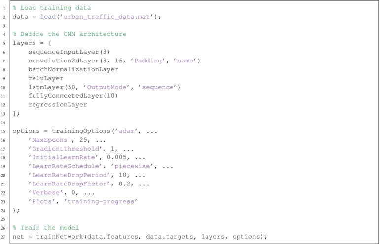
Structured data input is crucial for the effective operation of machine learning models. The following Python code snippet illustrates how to structure the data into a 90x3 tensor, suitable for feeding into our CNN-LSTM model. Each row in this tensor represents one minute of collected data across three critical network metrics: latency, bandwidth, and reliability. This structure supports the model’s requirement to analyze spatial-temporal dynamics for network management.
Listing 1: Structured Data Preparation for CNN-LSTM Model
Preprints 112183 i001
This structured approach to data not only provides the CNN-LSTM model with the required format for optimal processing but also encapsulates the essence of the network’s dynamic conditions within each minute interval. Each metric is carefully normalized and aligned within a structured array to maintain consistency and improve the predictive accuracy of the model. The listing includes detailed normalization steps, where each network performance metric is adjusted to a specific range. This is essential to maintain uniformity in input scales and to prevent any feature from dominating the model’s training process due to scale discrepancies.
By stacking the normalized data into a 90x3 tensor with ‘np.stack’, we ensure that the data retains its chronological order across different metrics. This structure allows the CNN to extract spatial features effectively while the LSTM can track temporal patterns, both critical for making informed predictions in a network environment.
The choice of stacking along ‘axis=1’ ensures that each row of the tensor corresponds to a single time interval, with columns representing different metrics. This alignment is crucial for the CNN-LSTM model to process each time slice as a unified snapshot of network conditions, enhancing the detection of underlying patterns and dependencies.

5.3. CNN-LSTM Implementation in MMS-DSR

The integration of a Convolutional Neural Network (CNN) and Long Short-Term Memory model within MMS-DSR harnesses advanced predictive capabilities that significantly enhance routing decisions in dynamically changing urban environments. This subsection discusses the implementation of the CNN-LSTM model, using MATLAB for model training and OMNet++ for real-time simulation in traffic prediction and route optimization.

5.4. Model Training and Preparation

The CNN-LSTM model is trained using historical traffic data, encompassing a variety of urban traffic scenarios. Training is conducted using MATLAB, known for its robust environment for machine learning model development and simulation.
Listing 2: Training the CNN-LSTM Model in MATLAB
Preprints 112183 i002
In the Listing 2 the data variable could include metrics such as latency, bandwidth, and reliability which are crucial for understanding traffic flow and network performance. The convolutional layers are designed to extract spatial features from the sequential input data, which are crucial for identifying patterns. LSTM layers follow to capture temporal dependencies, important for forecasting traffic conditions. Training Options: parameters such as MaxEpochs, MiniBatchSize and InitialLearnRate are tuned to optimize the learning process, ensuring the model adequately learns from historical data to make accurate predictions about traffic patterns.

5.5. Integration with OMNet++

Once trained, the CNN-LSTM model is integrated into OMNet++ for real-time simulation and decision-making. The trained model parameters are imported into OMNet++, interfacing with Python to handle data preprocessing and prediction execution.
  • Model Import: the MATLAB-trained model parameters are converted and imported into OMNet++ using a Python interface.
  • Data Preprocessing: traffic data from SUMO (Simulation of Urban MObility) are preprocessed to match the CNN-LSTM model’s input requirements.
  • Prediction Execution: the CNN-LSTM model executes within the OMNet++ simulation, predicting future traffic conditions based on real-time data.
  • Route Adjustment: routing decisions are dynamically adjusted based on the model’s predictions to optimize traffic flow and reduce communication latency.
The Figure 7 demonstrates the sequential process from data acquisition to dynamic routing decision-making within the MMS-DSR protocol. Here’s a breakdown of each stage depicted in the figure:
Traffic Data (SUMO): this block represents the initial stage where traffic data is gathered from the Simulation of Urban MObility (SUMO). SUMO is extensively used to generate realistic vehicular mobility patterns which are critical for testing traffic management systems. Preprocessing: once the traffic data is collected, it undergoes preprocessing to transform the data into a format suitable for neural network consumption. This includes normalization of features, conversion of categorical data into numerical formats, and structuring the data into tensors that the CNN-LSTM model can process.
CNN-LSTM Model: at this core stage, the preprocessed data is fed into the CNN-LSTM model. The CNN layers extract spatial features from the data, identifying key patterns such as areas of high congestion. Following this, the LSTM layers analyze these features over time to detect temporal patterns and predict future traffic conditions.
Prediction: the predictions made by the CNN-LSTM model are crucial for anticipating future traffic dynamics. These predictions include potential congestions, optimal traffic routes, and expected changes in traffic flow.
Routing (MMS-DSR): based on the predictions from the CNN-LSTM model, the MMS-DSR routing protocol dynamically adjusts the vehicular routes. This step helps to optimize traffic flow, reducing congestion, and enhancing overall communication efficiency within the urban network.

6. Adapting MMS-DSR from MANETs to VANETs for Smart Cities

As urban centers continue to grow and evolve, the integration of intelligent transportation systems becomes crucial for enhancing urban mobility and safety. Vehicular Ad-Hoc Networks are emerging as a centric technology in this context, promising to transform conventional traffic systems into dynamic, automated, and communicative networks. Unlike Mobile Ad-Hoc Networks that are designed for relatively stable environments with moderate mobility patterns, VANETs cater to high-speed vehicles within the complex and rapidly changing urban contexts. The adaptation of the Modified Dynamic Source Routing protocol from MANETs to VANETs is not merely a technical necessity but a strategic imperative to meet the specialized demands of modern smart cities. This section explores the critical adaptations required for MMS-DSR to effectively function in the VANET environment, addressing unique challenges and exploiting the opportunities presented by urban infrastructural advancements.

6.1. Introduction and System Requirements

Vehicular Ad-Hoc Networks, as a specialized subset of Mobile Ad-hoc Networks, are designed to meet the rigorous demands of automotive-based communication environments. The need for such a specialized approach is driven by distinct challenges characteristic of smart city contexts, which include high vehicle mobility, dense urban architecture, and the need for highly reliable and dynamic communication systems. VANETs address these challenges by adapting traditional MANET protocols to suit the high dynamics of urban vehicular movements and the specific network infrastructure requirements of cities.
In VANETs, vehicles often travel at high speeds across diverse urban and highway environments, resulting in highly dynamic network topology changes. For simplicity we consider an urban context. Thus, vehicle speeds are assumed to be relatively lower than highway conditions. Traditional routing protocols like MMS-DSR must be enhanced to rapidly manage these frequent changes without significant delays, ensuring timely and reliable route updates that support continuous and dependable communication.
The urban scenario introduces physical barriers such as buildings, underpasses, and bridges, which can impede wireless signals. VANET adaptations of MMS-DSR must consider three-dimensional geographic data to optimize routing paths based on the likelihood of signal degradation, ensuring that the routing decisions are both context-aware and adaptive to the urban environment.

6.2. Mathematical Formalization for VANET

To adapt the previous Mathematical Formalization from MANETs to VANETs, we need to consider the specific characteristics and requirements of VANETs. In particular, in mathematical formalization for VANETs we must incorporate additional parameters such as the Density of the Vehicles, the Distance of the Vehicle from the Destination, and the Trajectory of the Vehicle [54,55]. These parameters are crucial for ensuring efficient and reliable routing in highly dynamic vehicular environments.
Vehicle Density (De): vehicle density measures the concentration of vehicles within a specific area of the network. It is a critical metric for evaluating network congestion, as high vehicle density can lead to increased communication delays and packet collisions.
D e ( r , t ) = TNVA AS
where: T N V A is the total number of vehicles in the area, and A S is the area size. High vehicle density indicates potential congestion, which can negatively impact communication reliability and latency. Understanding vehicle density helps in optimizing routing decisions to avoid congested areas and improve overall network performance.
Vehicle Distance (Di): vehicle distance is the Euclidean distance of the vehicle in the route from the destination.
D i ( r , t ) = exp d i d ref ζ
where: d i is the Euclidean distance of the vehicle from the destination, d ref is a reference distance, ζ is an attenuation factor.
Vehicle distance provides insight into the potential longevity of communication links, allowing for better route stability. Routes with shorter distances to the destination are preferred, as they are likely to offer more reliable communication.
Vehicle Trajectory (T): vehicle trajectory measures the predicted path towards the destination for the vehicle in the route, considering its current and future positions. This metric helps in assessing the alignment of vehicle movements with the desired route.
T ( r , t ) = exp Δ d ( t ) ζ d ref
where: Δ d ( t ) ζ = d ( t ) ζ d ( 0 ) ζ , d ( t ) is the future distance of the vehicle in the route to the destination at time t, d ( 0 ) is the current distance to the destination, d ref is a reference distance, ζ is an attenuation factor.
Vehicle trajectory helps in predicting the future alignment of vehicles with the intended route, ensuring that the selected path remains optimal over time. Routes with stable trajectories are preferred as they minimize deviations and potential disruptions in communication.
To predict the next position ( x i + 1 , y i + 1 ) of the vehicle, we use the current velocity vector ( v x , v y ) and the time interval Δ t :
x i + 1 = x i + v x · Δ t
y i + 1 = y i + v y · Δ t
where: ( x i , y i ) are the current coordinates of the vehicle, v x and v y are the velocity components in the x and y directions, respectively, and Δ t is the time interval.
Vehicle trajectory helps in predicting the future alignment of vehicles with the intended route, ensuring that the selected path remains optimal over time. Routes with stable trajectories are preferred as they minimize deviations and potential disruptions in communication.
To avoid making the article too heavy, we refer to the articles cited [54,55] for more details on the formulas relating to the parameters.
Below is the adapted mathematical formalization for VANETs:
VANETs Score Computation: the overall score for each route, S, is computed as:
S ( r , t ) = w 1 · 1 L ( r , t ) + w 2 · B ( r , t ) + w 3 · R ( r , t ) + w 4 · B E ( r , t ) + w 5 · 1 D e ( r , t ) + w 6 · 1 D i ( r , t ) + w 7 · 1 T ( r , t )
where w 1 , w 2 , w 3 , w 4 , w 5 , w 6 , and w 7 are the weights for latency, bandwidth, reliability, beamforming efficacy, density, distance, and trajectory respectively.
The scoring function S ( r , t ) for VANETs is defined as:
S ( r , t ) = α · i = 1 n w i ( t ) · v i ( r ) + δ · P p r e d i c t i o n ( r , t ) + λ · B F ( r , t )
where: v i ( r ) are the route metrics, w i ( t ) are the time-dependent weights, α is a weighting factor for the summation real-time term, δ integrates the predictive reliability score P p r e d i c t i o n ( r , t ) , λ is a weighting factor for the beamforming score B F ( r , t ) .
When D e increases (i.e., more vehicles in a given area), it indicates higher congestion, leading to increased communication delays and potential packet collisions. Consequently, the score for routes through such areas would decrease, signaling less optimal paths. As D i increases, the vehicle is farther from the destination, likely leading to less reliable communication links. The score for such routes decreases because longer distances can result in higher latency and potential disconnections. An increase in T (indicating a less predictable or more erratic trajectory) implies that the vehicle’s future positions are less aligned with the optimal path, leading to potential disruptions in communication. This decreases the route score.
Integrating these new metrics is critically important. Vehicle Distance ( D i ) and Vehicle Trajectory (T) metrics account for the relative position and movement of vehicles towards the destination, helping to predict the stability and longevity of communication links. Vehicle Density ( D e ) assesses the congestion level around each vehicle, influencing the likelihood of packet collisions and network performance.

6.2.1. Numerical Illustration for VANET

To provide a concrete understanding of the MMS-DSR scoring mechanism for VANETs, we present a numerical example with a network topology, as illustrated in Figure 8. This hypothetical scenario considers several candidate routes, each with different metrics for latency, bandwidth, reliability, vehicle density, vehicle distance, vehicle trajectory, and beamforming efficacy (BE), typical of diverse urban paths.
The routes and their respective metrics are summarized in Table 5.
Table 6. Example routes with associated metrics.
Route L (ms) B (Mbps) R De Di (m) T (m) BE
r 1 10 50 0.9 20 100 10 15
r 2 8 40 0.95 30 120 8 18
r 3 12 60 0.85 25 150 12 12
r 4 15 45 0.92 15 140 15 17
r 5 9 55 0.88 22 130 9 14
r 6 10 50 0.9 20 100 10 15
r 7 8 40 0.95 30 120 8 18
r 8 12 60 0.85 25 150 12 12
r 9 15 45 0.92 15 140 15 17
r 10 9 55 0.88 22 130 9 14
Using the scoring function we assume the following parameters: δ = 0.2 , λ = 0.3 , β = 0 , Experience E = 10 , dynamic weights at time t: w 1 ( t ) = 0.3 , w 2 ( t ) = 0.2 , w 3 ( t ) = 0.1 , w 4 ( t ) = 0.05 , w 5 ( t ) = 0.1 , w 6 ( t ) = 0.15 , w 7 ( t ) = 0.1 .
The Predictive reliability scores at time t: P p r e d i c t i o n ( r 1 , t ) = 0.92 , P p r e d i c t i o n ( r 2 , t ) = 0.87 , P p r e d i c t i o n ( r 3 , t ) = 0.90 , P p r e d i c t i o n ( r 4 , t ) = 0.91 , P p r e d i c t i o n ( r 5 , t ) = 0.89 , P p r e d i c t i o n ( r 6 , t ) = 0.92 , P p r e d i c t i o n ( r 7 , t ) = 0.87 , P p r e d i c t i o n ( r 8 , t ) = 0.90 , P p r e d i c t i o n ( r 9 , t ) = 0.91 , P p r e d i c t i o n ( r 10 , t ) = 0.90 .
The Beamforming Factor (BF) scores at time t: B F ( r 1 , t ) = 20 , B F ( r 2 , t ) = 22.5 , B F ( r 3 , t ) = 15 , B F ( r 4 , t ) = 21 , B F ( r 5 , t ) = 19 , B F ( r 6 , t ) = 20 , B F ( r 7 , t ) = 22.5 , B F ( r 8 , t ) = 20 , B F ( r 9 , t ) = 22.5 , B F ( r 10 , t ) = 15 .
To ensure fair comparison, the metrics are normalized to a [0, 1] scale using the formula:
x norm = x x min x max x min
Table 7. Normalized metrics for each route.
Route L Norm B Norm R Norm De Norm Di Norm T Norm BE Norm
r1 0.286 0.50 0.5 0.20 0.0 0.20 0.500
r2 0.000 0.00 1.0 0.60 0.4 0.00 1.000
r3 0.571 1.00 0.0 0.40 1.0 0.40 0.000
r4 1.000 0.25 0.7 0.00 0.8 0.60 0.833
r5 0.143 0.75 0.3 0.35 0.6 0.25 0.333
r6 0.286 0.50 0.5 0.20 0.0 0.20 0.500
r7 0.000 0.00 1.0 0.60 0.4 0.00 1.000
r8 0.571 1.00 0.0 0.40 1.0 0.40 0.000
r9 1.000 0.25 0.7 0.00 0.8 0.60 0.833
r10 0.143 0.75 0.3 0.35 0.6 0.25 0.333
The Predictive reliability scores at time t were also normalized obtaining the following values: P p r e d i c t i o n N o r m ( r 1 , t ) = 1.0 , P p r e d i c t i o n N o r m ( r 2 , t ) = 0.0 , P p r e d i c t i o n N o r m ( r 3 , t ) = 0.6 , P p r e d i c t i o n N o r m ( r 4 , t ) = 0.8 , P p r e d i c t i o n N o r m ( r 5 , t ) = 0.4 , P p r e d i c t i o n N o r m ( r 6 , t ) = 1.0 , P p r e d i c t i o n N o r m ( r 7 , t ) = 0.0 , P p r e d i c t i o n N o r m ( r 8 , t ) = 0.6 , P p r e d i c t i o n N o r m ( r 9 , t ) = 0.8 , P p r e d i c t i o n N o r m ( r 10 , t ) = 0.6 .
The Beamforming Factor (BF) scores at time t were normalized obtaining the following values: B F N o r m ( r 1 , t ) = 0.667 , B F N o r m ( r 2 , t ) = 1.000 , B F N o r m ( r 3 , t ) = 0.000 , B F N o r m ( r 4 , t ) = 0.800 , B F N o r m ( r 5 , t ) = 0.533 , B F N o r m ( r 6 , t ) = 0.667 , B F N o r m ( r 7 , t ) = 1.000 , B F N o r m ( r 8 , t ) = 0.667 , B F N o r m ( r 9 , t ) = 1.000 , B F N o r m ( r 10 , t ) = 0.000 .
The scoring function S ( r , t ) for each route is calculated using the normalized values.
For example for r 1 we have:
S ( r 1 , t ) = 0.5 × 0.3 · 0.286 + 0.2 · 0.50 + 0.1 · 0.5 + 0.05 · 0.2 + 0.1 · 0.2 + 0.15 · 0.0 + 0.1 · 0.2
+ 0.2 · 1.0 + 0.3 · 0.667
S ( r 1 , t ) = 0.5 × ( 0.0858 + 0.1 + 0.05 + 0.01 + 0.02 + 0.0 + 0.02 ) + 0.2 + 0.3 · 0.667
S ( r 1 , t ) = 0.1429 + 0.2 + 0.2001
S ( r 1 , t ) = 0.5429
Repeating the same calculations for each route we will obtain the following values:
Table 8. Scoring Function values for each route after normalization.
Route Scoring Function (SF)
r1 0.5429
r2 0.5500
r3 0.4700
r4 0.675833
r5 0.530000
r6 0.5429
r7 0.5500
r8 0.4700
r9 0.675833
r10 0.530000
Even if by applying the scoring function, the paths r 4 and r 9 emerge as the optimal route with the highest score of 0.675833 , we must remember that in the classic DSR protocol, the primary metric for selecting the optimal path is typically the number of hops. Carrying out the route analysis of the graph illustrated in Figure 9, the possible paths from source to destination and the related Scoring Function (SF) values are shown in Table 9:
Table 9. Paths, Routes, and Total Scoring Functions (SF).
Path Routes Total SF
A → B → J r1 + r6 0.5429 + 0.5429 = 1.0858
A → C → J r2 + r7 0.5500 + 0.5500 = 1.1000
A → D → J r3 + r8 0.4700 + 0.4700 = 0.9400
A → B → E → J r1 + r4 + r9 0.5429 + 0.675833 + 0.675833 = 1.894566
A → C → F → J r2 + r5 + r10 0.5500 + 0.530000 + 0.530000 = 1.610000
Considering that MMS-DSR prioritizes the route with the highest cumulative scoring function (SF) and minimum number of hops, the chosen optimal path would be:
A C J with a total S F of 1.1000 .
In conclusion, this numerical illustration demonstrates the effectiveness of MMS-DSR’s scoring engine and shows how it can determine the optimal path in a network topology, considering various metrics and beamforming efficacy.

6.3. Selection of DSR Over Enhanced OLSR

The choice of Dynamic Source Routing (DSR) over Enhanced Optimized Link State Routing for Vehicular Ad-hoc Networks is primarily influenced by the distinct operational characteristics of DSR, which align well with the high mobility and variable network conditions typical of urban smart city environments. DSR offers several strategic advantages that make it particularly suited for such settings:
  • Adaptability to Network Changes: DSR utilizes an on-demand routing strategy, which allows it to efficiently manage the high frequency of topological changes without the need for constant route updates. This capability is crucial in urban areas, where vehicles frequently enter and exit the network, leading to rapid changes in network topology.
  • Reduced Overhead: unlike OLSR, which requires regular broadcasting of link-state information to all nodes within the network, DSR minimizes communication overhead by maintaining routes only when necessary. This approach not only conserves bandwidth but also reduces the computational burden on network nodes, enhancing overall network performance.
  • Efficiency in Dense Networks: DSR’s on-demand nature ensures that routing paths are established based on current network conditions, providing optimized routes and avoiding the pitfalls of pre-determined paths that may no longer be optimal in dynamically changing environments.
  • Flexibility in High Mobility Scenarios: DSR is particularly advantageous in scenarios where vehicle speeds and network densities change rapidly. The protocol’s flexibility allows it to adapt quickly, ensuring that communication remains robust even as vehicles move at high speeds and network configurations shift.
  • Scalability: the on-demand nature of DSR scales well with the increasing number of vehicles in urban settings. As smart cities grow and more vehicles are equipped with communication capabilities, DSR can efficiently handle the expanding network without suffering from the overhead associated with maintaining multiple routes simultaneously.
Enhanced OLSR, while robust in more stable and less dense networks, tends to perform less efficiently in the variable urban settings typical of VANETs. The frequent transmission of topology control messages required by OLSR can lead to significant network congestion, particularly in dense urban areas where connectivity needs to be managed more judiciously. The proactive nature of OLSR, which involves the periodic exchange of control messages to maintain route tables, can result in excessive bandwidth consumption and increased latency, especially in highly dynamic environments.
Future-Proofing Smart City Communications: by focusing on the structural and operational enhancements necessary for VANETs, the adapted DSR approach ensures that the protocol can meet the high demands of modern smart city applications. This includes preparing for future integrations and improvements in vehicular communication technology, such as the incorporation of machine learning algorithms for predictive routing and the integration of next-generation wireless technologies.
We want to highlight the operational differences between DSR and Enhanced OLSR within VANETs. The DSR routing process demonstrates an on-demand routing strategy that processes input data, performs dynamic routing, and establishes optimized paths based on current network conditions. This approach minimizes unnecessary routing overhead and adapts quickly to changes in network topology, making it highly efficient for urban environments with high vehicle mobility.
In contrast, the OLSR routing process illustrates a proactive routing strategy. OLSR continuously updates its routing tables through periodic control message exchanges, regardless of actual data traffic requirements. While this approach ensures that route information is always available, it can lead to significant bandwidth consumption and increased latency in highly dynamic networks, as the constant exchange of control messages can congest the network and delay data transmission.
By focusing on the structural and operational enhancements necessary for VANETs, the adapted DSR approach ensures that the MMS-DSR protocol can meet the high demands of modern smart city applications, preparing for future integrations and improvements in vehicular communication technology. The DSR protocol’s ability to efficiently handle dynamic changes in network topology makes it a superior choice for VANETs over Enhanced OLSR, which is more suited for less dynamic, stable network environments.
In conclusion, the selection of DSR over Enhanced OLSR for VANETs is driven by the need for a flexible, efficient, and scalable routing protocol that can adapt to the unique challenges of urban vehicular networks. The on-demand nature of DSR, coupled with its reduced overhead and adaptability, makes it the optimal choice for supporting the high mobility and variable network conditions characteristic of VANETs in smart cities.

7. Considered Scenario for MMS-DSR

The envisioned application scenario for Multi-metric Scoring Dynamic Source Routing is within a Vehicular Ad-hoc Network in a smart urban environment. This section describes the implementation of MMS-DSR in a vehicle-to-infrastructure (V2I) context, exploiting advanced communication technologies such as Multi-User MIMO (MU-MIMO) systems and an intelligent central controller that manages dynamic beamforming and deploys machine learning techniques for optimal routing.

7.1. Scenario Description

The scenario is set in a densely populated urban area equipped with smart city infrastructure. Road Side Units (RSUs) are deployed at strategic locations such as intersections, parking lots, and frequent congestion areas. Each RSU is equipped with MU-MIMO capabilities, allowing it to communicate simultaneously with multiple vehicles.
  • Network Configuration: the network consists of numerous vehicles and RSUs, each embedded with advanced communication technology to handle high-density information exchange. RSUs serve as the backbone of the urban vehicular network, providing not only connectivity but also acting as nodes that collect and process traffic data.
  • Role of MU-MIMO: MU-MIMO technology in RSUs enables handling of high throughput demands and supports extensive device connectivity. This technology significantly enhances network efficiency by allowing multiple vehicles to receive and transmit data simultaneously through spatial multiplexing.
  • Dynamic Beamforming: beamforming techniques are employed to direct signals towards specific vehicles, improving signal quality and reducing interference, which is crucial in urban environments with numerous obstructions.

7.2. Machine Learning-Enhanced Routing

A central controller utilizes machine learning algorithms, specifically a combination of Convolutional Neural Networks (CNNs) and Long Short-Term Memory networks, to predict traffic patterns and optimize routing decisions dynamically.
  • CNN-LSTM Model: the CNN component analyzes spatial features from the urban environment, such as vehicle density, vehicle distance, and vehicle trajectory, while the LSTM part processes temporal data, learning from past traffic patterns to predict future conditions.
  • Data Handling: real-time data from various sensors on vehicles and static city sensors are transmitted to the RSUs, where they are processed and analyzed. This data includes vehicle speed, location, direction of travel, and other environmental factors that are used to compute the metrics.
  • Route Optimization: based on the analysis, the central controller calculates the optimal routes for each vehicle, updating routes in real-time to respond to dynamic urban conditions like traffic jams, accidents, or road closures.

7.3. Practical Implementation

A practical example of this scenario involves emergency response vehicles during peak traffic times. Using MMS-DSR, the system can prioritize emergency vehicle communications, dynamically adjusting routes and beamforming patterns to ensure the quickest and safest path through congested city streets.
  • Emergency Routing: when an emergency call is received, the system immediately calculates the most efficient route for emergency vehicles, considering current traffic conditions and upcoming changes predicted by the CNN-LSTM model. This route optimization ensures that the emergency vehicles reach their destination as quickly as possible, avoiding traffic congestion and other potential delays.
  • Inter-Vehicle Communication: emergency vehicles continuously communicate their status and position to nearby RSUs. The RSUs coordinate with each other and with the central controller to manage traffic lights, dynamically adjust beamforming directions, and notify other vehicles to clear the path for the emergency vehicles. This coordinated effort helps maintain a clear and efficient route for emergency responders.
  • Real-Time Updates: the system provides real-time updates to emergency vehicles, allowing them to adapt to changing conditions, such as sudden roadblocks or new traffic patterns. This adaptability is crucial for maintaining efficient and safe routes during emergencies.

7.4. Visualization of the Scenario

The following figure provides a detailed visual representation of the MMS-DSR operational framework in a smart city VANET environment. It illustrates how various components such as Road-Side Units (RSUs), vehicles, and a central controller interact to optimize vehicular communication and traffic management.
This Figure 10 depicts RSUs (RSU1 and RSU2) strategically placed along a route to communicate with passing vehicles (V1, V2, V3, V4). These RSUs serve as critical nodes that not only relay information from the vehicles back to a central controller but also receive routing instructions and beamforming configurations from the controller. The central controller processes real-time traffic and vehicular data to optimize routes, which are then communicated back to the vehicles via RSUs. This ensures that vehicles are always taking the most efficient paths, avoiding congested areas, and minimizing travel times. By continuously updating beamforming strategies, the RSUs can adjust their communication beams to maximize signal clarity and strength, ensuring reliable and uninterrupted communication. Vehicles constantly send data to the RSUs for maintaining up-to-date traffic models and for emergency responses.

8. Simulation and Evaluation

This section explores the empirical validation of the MMS-DSR protocol, showcasing its effectiveness in both Mobile Ad Hoc Networks and Vehicular Ad Hoc Networks. The protocol’s capabilities are evaluated against established standards such as traditional DSR, SOL-DSR, and Enhanced OLSR. We particularly focus on its performance in an urban setting, simulating the dynamic and complex environment of the Metropolitan area of Reggio Calabria, Italy.

8.1. Simulation Setup

Simulations utilize OMNeT++ integrated with SUMO (Simulation of Urban MObility) and the inet framework to emulate realistic urban MANET and VANET scenarios. SUMO manages the vehicular traffic within the city, reflecting accurate vehicle movements and interactions, while inet supports advanced network simulations using the 802.11ax HE mode that we designed in [56]. This setup allows for the detailed assessment of the MMS-DSR protocol in managing communication in densely populated urban areas.
Figure 11. SUMO simulation scenario in Reggio Calabria.
Preprints 112183 g011

8.2. Simulation Parameters

We configure our simulation to reflect the unique traffic and networking conditions of the Metropolitan area of Reggio Calabria. Special attention is given to the placement of Road-Side Units (RSUs) equipped with MU-MIMO technology, optimized for beamforming capabilities to enhance communication efficiency across the network.
Table 10. Simulation Parameters tailored for Reggio Calabria’s urban environment.
Parameter Value
Tone Configuration 26, 242, 2x996
Protocols DSR, MMS-DSR, SOL-DSR, Enhanced OLSR
MIMO Configurations 10x10
Seed Variability Multiple sets
Confidence Interval 95%
Simulation Time 1000 seconds
Number of Nodes 20 to 100
Data Rate Up to 9607.5 Mbps
Network Standard IEEE 802.11ax
Mobility Model Random Waypoint, Manhattan
Traffic Type UDP, CBR, VBR
TX Data App UDPBasicApp
RX Data App UDPSink
Packet Size 1500 bytes
Node Sensitivity -120 dBm
Simulation Tools OMNeT++, SUMO, Veins
RSU Placement Strategically placed at major intersections
RSU Quantity 15 RSUs covering key traffic nodes
The RSUs are strategically placed at major intersections and points of high vehicle density to maximize the MU-MIMO gains and beamforming effectiveness, ensuring optimal coverage and minimal communication disruption. This placement is based on traffic flow data, which indicates areas of frequent congestion and high vehicular mobility, making them critical points for effective traffic management and emergency response facilitation.

8.3. RSU Configuration and Placement Justification

In the Metropolitan area of Reggio Calabria, we deploy a total of 15 RSUs. These units are crucial for the network’s infrastructure, particularly for managing the high-speed vehicular communication required in urban settings. The RSUs are equipped with advanced MU-MIMO systems that allow for significant enhancements in signal directivity and strength through beamforming techniques.
Each RSU’s location is selected based on a comprehensive analysis of traffic patterns and vehicle density, ensuring that each unit can effectively manage the communication demands of its surrounding area. This strategic placement not only maximizes the coverage and efficiency of the network but also significantly enhances the reliability and speed of the communication.

8.4. Implementation of Comparative Protocols
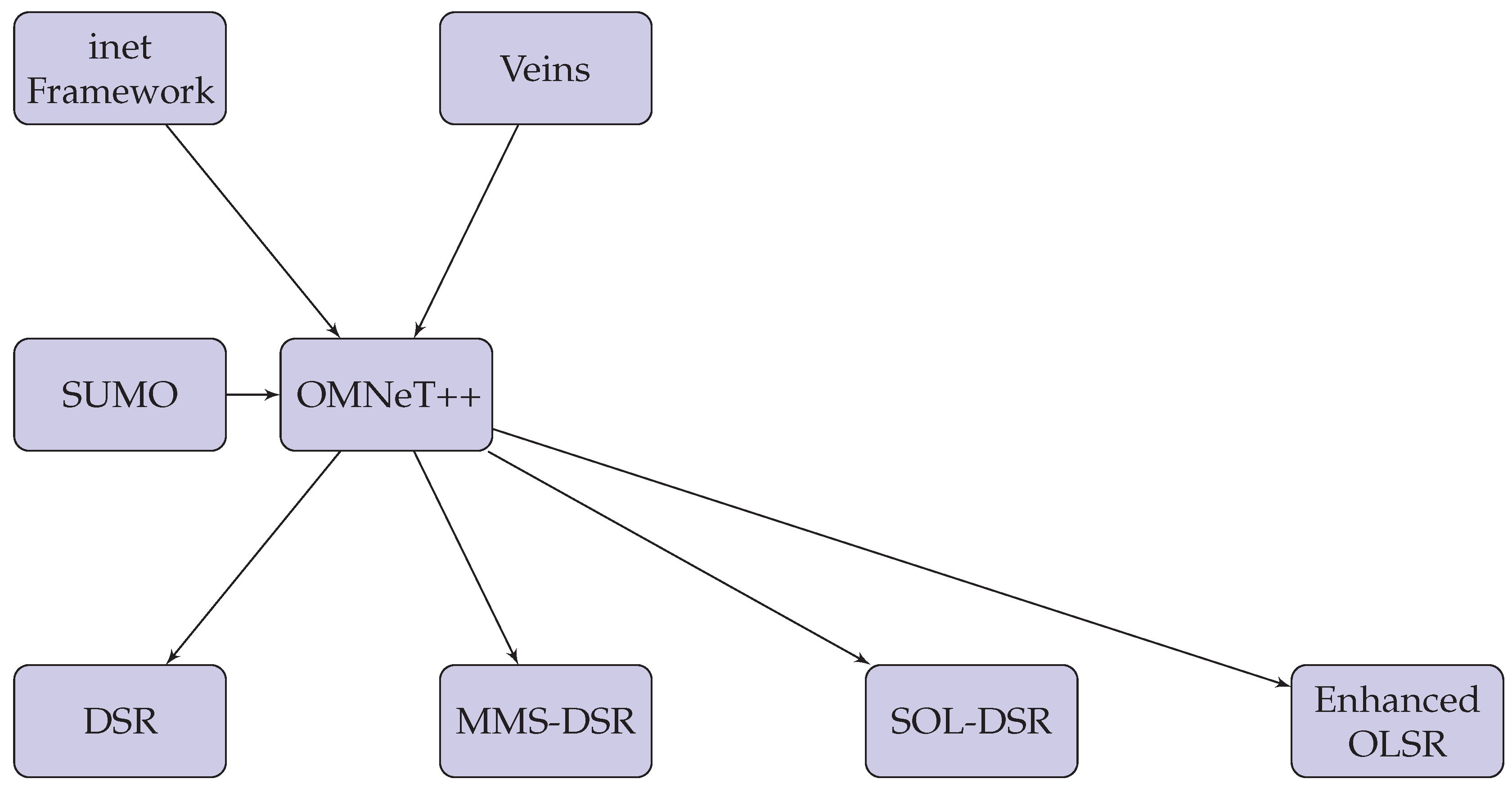
In the evaluation of MMS-DSR, we compare its performance not only with the traditional DSR protocol but also with two advanced adaptations: SOL-DSR and Enhanced OLSR. These comparisons are crucial to validate the effectiveness and efficiency of MMS-DSR in handling urban vehicular communications. Here we detail the implementation of these protocols within the OMNeT++ simulation framework, alongside the classic DSR protocol provided by the inet framework. Classic DSR, a well-established routing protocol in ad hoc networks, is utilized as a baseline for our simulations. This protocol is integrated into the inet framework, which provides a robust implementation suitable for both MANETs and VANETs. The inet framework’s version of DSR follows the standard routing mechanism where nodes dynamically discover and maintain source routes to all other nodes in the network. SOL-DSR has been Implemented in Python, the DRL model is interfaced with OMNet++ through the Veins framework, which allows for the integration of machine learning algorithms with traditional network simulation components. The DRL algorithm continuously updates its policy based on the feedback from the network, selecting routes that minimize delays and maximize throughput. The model is trained offline using a synthetic dataset generated from simulated network scenarios, and the trained model is then deployed in the simulation to make real-time routing decisions. The implementation of Enhanced OLSR in OMNeT++ is carried out using the inet framework, with modifications to the standard OLSR protocol to include "greedy forwarding" techniques. These techniques utilize dynamic assessment of neighbor proximity, based on the real-time vehicular data provided by SUMO, to make forwarding decisions. This ensures that the routing is highly responsive to the urban dynamics, providing improved performance in terms of latency and network overhead in densely populated city scenarios. All protocols are simulated under identical network conditions in OMNeT++ using the same vehicular mobility patterns generated by SUMO. This ensures that the comparison is fair and highlights the relative strengths and weaknesses of each protocol in managing urban vehicular communications. Metrics such as end-to-end delay, packet delivery ratio, and routing overhead are measured to evaluate and compare the performance of the protocols.
The diagram in Figure 12 illustrates the integration of the simulation tools and routing protocols used in our study. The inet framework provides foundational network functionalities and implements the classic DSR protocol, which serves as our baseline comparison. SUMO generates realistic vehicular movement data for simulating urban traffic patterns. Veins play a crucial role by bridging the gap between OMNet++ simulations and real-world applications by incorporating machine learning models, such as those used in SOL-DSR, into network simulations. This setup ensures that our simulations are not only accurate but also reflective of actual urban vehicular environments. Each protocol, including our enhanced MMS-DSR, interacts within the OMNeT++ environment to assess its effectiveness against urban mobility challenges, providing a comprehensive evaluation of routing efficiency and communication reliability.
Figure 12. Visualization of protocol implementation and interactions with simulation tools.
Preprints 112183 g012

8.5. Performance Metrics

We focus on throughput, end-to-end latency, and route discovery time to assess the MMS-DSR protocol’s performance under varying network loads and conditions. Throughput measures the network’s capacity to deliver data successfully, reflecting the efficiency of data handling by the protocol.
Figure 13. Throughput comparison across varying number of vehicles.
Preprints 112183 g013
Throughput is a critical metric for assessing the performance of routing protocols in Vehicular Ad Hoc Networks. The MMS-DSR protocol showcases an exemplary integration of machine learning techniques, specifically Long Short-Term Memory networks, to optimize routing decisions and enhance network performance effectively. This integration is evident in the near-linear growth of throughput observed in our simulations, where MMS-DSR accelerates from 1200 Mbps with 10 vehicles to a remarkable 9400 Mbps with 100 vehicles. This growth not only underscores the effectiveness of LSTM-based predictive modeling in optimizing data paths but also highlights the protocol’s ability to dynamically minimize congestion, even as the network scales.
In comparison to other protocols like SOL-DSR and Enhanced OLSR, MMS-DSR demonstrates superior scalability and efficiency. For instance, at 100 vehicles, MMS-DSR achieves 9400 Mbps, significantly outperforming SOL-DSR’s 6600 Mbps and Enhanced OLSR’s 5000 Mbps. This substantial throughput advantage is attributable to the multi-metric scoring engine of MMS-DSR, which dynamically adjusts the weights of various routing metrics based on current network conditions, combined with the predictive power of LSTM that enhances route selection and management. This approach enables MMS-DSR to maintain high throughput levels, even as network conditions change, by proactively adapting to shifts in bandwidth availability, vehicle density, and network reliability.
Urban environments, characterized by high vehicle mobility and fluctuating traffic densities, pose unique challenges for routing protocols. MMS-DSR addresses these challenges head-on by utilizing its LSTM networks to predict and adapt to dynamic network conditions. For example, MMS-DSR’s throughput remains stable and high in urban scenarios, a testament to its ability to predict potential bottlenecks and disruptions in data flow. The protocol’s predictive capabilities allow it to reroute data preemptively around congested areas and potential points of disruption, ensuring smooth data transmission. For instance, even as the number of vehicles increases, MMS-DSR maintains a throughput increase from 1200 Mbps at 10 vehicles to 9400 Mbps at 100 vehicles, showcasing less than a 1% drop in efficiency compared to the initial performance, unlike traditional protocols which exhibit larger declines.
Furthermore, MMS-DSR’s efficiency in managing network resources is highlighted by its intelligent routing decisions that balance load across the network, preventing the over-utilization of any single path and supporting uniform data distribution. This is crucial in maintaining high throughput levels, as seen in our simulations where MMS-DSR consistently outperforms other protocols across various vehicle densities and conditions. For example, when the vehicle density increases from 50 to 100 vehicles, MMS-DSR manages to keep its throughput nearly optimal, showcasing only a minimal decrease in performance, which is significantly lower than the declines observed in protocols like SOL-DSR and Enhanced OLSR.
Also, the urban scenario analysis further demonstrates the robustness of MMS-DSR in handling the dynamic and often unpredictable environments of city scenario. The protocol’s machine learning models enable it to effectively navigate frequent topology changes and varying traffic densities, ensuring optimal route selection and minimal delays. This capability is particularly important during peak traffic hours in cities, where MMS-DSR can predict increased vehicle density and adjust routes in real-time to avoid slow-moving areas, thereby maintaining high throughput levels.
Figure 14. Throughput comparison across varying vehicle speeds.
Preprints 112183 g014
MMS-DSR also demonstrates superior performance in terms of throughput across varying vehicle speeds. At a speed of 100 km/h, MMS-DSR achieves 9000 Mbps, which is significantly higher than SOL-DSR’s 7300 Mbps and Enhanced OLSR’s 6300 Mbps. This can be attributed to MMS-DSR’s adaptive routing strategies and predictive capabilities that effectively manage the dynamic nature of vehicular movement.
As vehicle speed increases, MMS-DSR’s ability to predict and adapt to changes in the network ensures that data packets are routed efficiently, avoiding potential disruptions and maintaining high throughput. For instance, even at high speeds, MMS-DSR’s throughput only decreases slightly from 1100 Mbps at 10 km/h to 9000 Mbps at 100 km/h, demonstrating its robustness and efficiency in high mobility scenarios. This minimal decrease in performance at higher speeds contrasts sharply with the more significant drops observed in other protocols.
Furthermore, the efficiency of MMS-DSR in managing network resources and avoiding congestion is evident as vehicle speeds increase. The protocol’s intelligent routing decisions, informed by LSTM predictions, ensure that data is transmitted smoothly even in high-speed environments, reducing the likelihood of packet loss and maintaining consistent throughput.

8.5.1. Average End-to-End Latency

Latency measures the time it takes for packets to travel from the source to the destination, indicating the responsiveness of the network.
Figure 15. Latency comparison in function of vehicle density.
Preprints 112183 g015
Figure 16. Latency comparison in function on vehicle speed.
Preprints 112183 g016
Latency is an essential metric for evaluating the responsiveness and efficiency of routing protocols in Vehicular Ad Hoc Networks. The MMS-DSR protocol demonstrates a significant advantage in managing latency, particularly evident in our simulation results, where latency increases from 20 ms at a density of 10 vehicles/km² to only 60 ms at 100 vehicles/km². This increase is notably lower compared to other protocols, such as SOL-DSR, which jumps from 25 ms to 75 ms, and Enhanced OLSR, which escalates from 30 ms to 85 ms under similar conditions. This remarkable performance by MMS-DSR can be primarily attributed to the integration of Long Short-Term Memory networks, which empower the protocol to proactively adjust routes in response to potential congestion and vehicle mobility, thereby avoiding common causes of delay.
The machine learning impact on MMS-DSR is profound, as its use of LSTM networks allows for predictive adjustments that preemptively mitigate potential delays. For instance, as vehicle density increases, leading to higher chances of congestion and complex vehicle interactions, MMS-DSR effectively uses its LSTM models to foresee and navigate around these potential bottlenecks. This proactive routing ensures that even in scenarios where vehicle density significantly increases, the latency remains optimally low. For example, when vehicle density increases from 50 to 100 vehicles/km², MMS-DSR exhibits only a minimal increase in latency from 40 ms to 60 ms, demonstrating an exceptional ability to manage and adapt to increased traffic without a corresponding steep rise in delay.
However, MMS-DSR’s adaptive routing capability is further highlighted in its consistent performance across various network configurations. Its ability to maintain lower latency under increasing vehicle density showcases the effective use of LSTM predictions to anticipate and adjust to potential delays dynamically. This ensures faster packet delivery, which is particularly beneficial in urban scenarios where quick response times are crucial. For instance, in a dense urban environment characterized by frequent stop-and-go traffic and variable vehicle speeds, MMS-DSR’s latency remains around 60 ms at 100 vehicles/km², significantly lower than the 75 ms for SOL-DSR and 85 ms for Enhanced OLSR. This is crucial for applications requiring timely data delivery, such as dynamic traffic light control and emergency vehicle routing, where delays can have significant implications.
The consistent low latency of MMS-DSR underscores its suitability for urban environments, where the dynamic movement of vehicles necessitates quick adaptability and responsive routing. The protocol’s machine learning-based predictive adjustments ensure timely data delivery, essential for safety and traffic management applications. For example, in scenarios involving emergency responses where vehicles need to communicate quickly with each other and with roadside infrastructure, MMS-DSR’s ability to keep latency low, despite increasing vehicle density and mobility, ensures that critical information is relayed without delay, supporting efficient emergency handling and enhancing overall urban mobility.
The detailed analysis of latency in MMS-DSR, with its integration of LSTM networks and adaptive routing strategies, reveals a protocol that is not only responsive and efficient but also highly adaptable to the varying dynamics of urban network environments. The protocol’s performance in maintaining low latency across different vehicle densities and speeds, and urban scenarios, combined with its robust machine learning capabilities, positions MMS-DSR as an advanced solution for future developments in VANET routing protocols, particularly for applications demanding quick and reliable communication in complex urban settings.

8.5.2. Route Discovery Time

The time required to discover a route reflects the protocol’s efficiency in establishing connectivity, especially in dynamic networks where rapid changes are common.
Figure 17. Route discovery time VS vehicle density.
Preprints 112183 g017
Figure 18. Route discovery time VS vehicle speed.
Preprints 112183 g018
Route discovery time is a crucial performance metric for routing protocols in Vehicular Ad Hoc Networks, particularly in high-mobility urban environments where rapid topological changes are common. MMS-DSR demonstrates superior performance in this aspect, with route discovery times increasing from only 15 ms at a density of 10 vehicles/km² to 55 ms at 100 vehicles/km². This progressive increase is significantly slower compared to other protocols like SOL-DSR and Enhanced OLSR, where times escalate more steeply from 20 ms to 70 ms and from 25 ms to 80 ms respectively under similar conditions. This highlights the effectiveness of the integrated machine learning model in MMS-DSR, which uses Long Short-Term Memory networks to predict and adjust routes dynamically, facilitating quick and efficient pathfinding even as network complexity increases.
The impact of machine learning on MMS-DSR is significant, particularly in how it optimizes route discovery times. The LSTM networks enable the protocol to preemptively adjust routes in response to real-time changes in the network topology. For instance, as vehicle density increases and the network becomes more congested, MMS-DSR efficiently predicts potential bottlenecks and reroutes data packets through less congested paths. This ability is reflected in the moderate increase in discovery times from 30 ms at 50 vehicles/km² to only 55 ms at 100 vehicles/km², demonstrating an exceptional capacity to handle increased traffic and complexity without a corresponding steep rise in discovery times.
Furthermore, MMS-DSR’s efficient pathfinding is evident across various network densities. Its lower discovery times, compared to other protocols, underscore its advanced algorithms and the features provided by LSTM predictions. These algorithms enable MMS-DSR to quickly adapt to topological changes and optimize routes without incurring excessive overhead. For example, in urban scenarios characterized by high mobility and frequent topological changes, MMS-DSR maintains discovery times around 55 ms for 100 vehicles/km², much lower than the 70 ms for SOL-DSR and 80 ms for Enhanced OLSR. This rapid route discovery is crucial for maintaining continuous and reliable communication in dynamic urban settings, supporting operational efficiency and safety in smart city applications.
In dense urban networks, where the interaction between vehicles is continuous and complex, MMS-DSR’s rapid route discovery capability ensures that communication delays are minimized. For instance, in scenarios involving real-time traffic information sharing or coordination among emergency vehicles, MMS-DSR’s ability to maintain low discovery times ensures that information is shared promptly, enhancing the responsiveness of urban transport systems and emergency services.
In summary, the detailed analysis of route discovery time in MMS-DSR, with its integration of LSTM networks and efficient pathfinding algorithms, reveals a protocol that is not only quick and responsive but also highly adaptable to the varying dynamics of urban environments. The protocol’s performance in maintaining low discovery times across different vehicle densities and speeds, urban scenarios, and under dynamic topological changes, combined with its robust machine learning capabilities, positions MMS-DSR as an advanced solution for future developments in VANET routing protocols, especially for applications demanding fast and reliable route establishment in complex and high-mobility urban settings.
To further validate the effectiveness of MMS-DSR, additional simulation results focusing on key performance metrics such as Packet Delivery Ratio (PDR), Routing Overhead, and Scalability can be discussed. These metrics provide a comprehensive view of the protocol’s performance in urban VANET environments, highlighting its robustness and efficiency.

8.5.3. Routing Overhead

Routing Overhead measures the extra communication required for maintaining the routing information, indicating the efficiency of the protocol.
MMS-DSR exhibits lower routing overhead compared to SOL-DSR, Enhanced OLSR, and traditional DSR, as depicted in Figure 19 and Figure 20. The overhead increases from 200 control packets at 10 vehicles/km² to 1600 control packets at 100 vehicles/km² and from 200 control packets at 10 km/h to 1550 control packets at 100 km/h. This is significantly lower than the 2000 control packets required by Enhanced OLSR and DSR. MMS-DSR’s on-demand routing strategy, combined with the predictive capabilities of LSTM networks, minimizes unnecessary control packet transmissions, thus reducing overhead and improving overall network efficiency.
Figure 19. Routing overhead comparison in function of vehicle density.
Preprints 112183 g019
Figure 20. Routing overhead comparison in function of vehicle speed.
Preprints 112183 g020
A key advantage of MMS-DSR is its ability to predict vehicle movements without relying on GPS systems. By utilizing predictive models that anticipate vehicle trajectories, MMS-DSR reduces the need for frequent route updates, which significantly lowers the routing overhead. This approach ensures efficient use of network resources and enhances the protocol’s scalability and adaptability in urban VANET environments.
The machine learning model in MMS-DSR, particularly the LSTM networks, plays a crucial role in this optimization. These networks forecast vehicle movements based on historical and real-time data, allowing the protocol to adjust routes dynamically and avoid congested areas. As vehicle density and speed increase, MMS-DSR maintains lower overhead by efficiently managing control packet transmissions and preventing unnecessary route discoveries. For example, at a vehicle density of 50 vehicles/km², MMS-DSR requires only 1000 control packets compared to 1500 for Enhanced OLSR, demonstrating its superior efficiency.
Furthermore, in high-density urban scenarios, MMS-DSR’s ability to predict and adapt to vehicle movements without GPS significantly reduces overhead. This is crucial for applications where network efficiency and resource management need to be handled. The protocol’s predictive capabilities enable it to maintain low overhead even as the number of vehicles and their speeds increase, ensuring reliable and efficient communication in dynamic and complex urban environments.
Basically, the detailed analysis of routing overhead in MMS-DSR, with its integration of predictive models and efficient control packet management, reveals a protocol that is not only efficient and scalable but also highly adaptable to the varying dynamics of urban VANET environments. The protocol’s performance in maintaining low overhead across different vehicle densities and speeds, combined with its robust machine learning capabilities, positions MMS-DSR as an advanced solution for future developments in VANET routing protocols, particularly for applications demanding efficient and reliable communication in complex urban settings.

8.5.4. Scalability

Scalability examines the protocol’s ability to handle increasing network sizes without significant performance degradation.
MMS-DSR demonstrates excellent scalability performance, as illustrated in Figure 21 and Figure 22. The Normalized Performance Index decreases from 0.95 with 10 vehicles/km² to 0.63 with 100 vehicles/km² and from 0.95 at 10 km/h to 0.63 at 100 km/h. This decline is less pronounced compared to SOL-DSR, Enhanced OLSR, and DSR. MMS-DSR’s machine learning-enhanced predictive capabilities and efficient routing strategies allow it to manage increasing network sizes effectively, ensuring consistent performance across various vehicle densities and speeds. This robustness is crucial for maintaining reliable communication in densely populated urban VANET environments.
Figure 21. Scalability comparison performance across increasing vehicle density.
Preprints 112183 g021
Figure 22. Scalability comparison performance across increasing vehicle speed.
Preprints 112183 g022
In high-density scenarios, MMS-DSR’s predictive modeling using Long Short-Term Memory networks allows it to anticipate and adapt to changes in vehicle movements and network conditions dynamically. This capability ensures that even as vehicle density and speed increase, MMS-DSR can maintain high performance with minimal degradation. For example, at a density of 100 vehicles/km² and speed of 100 km/h, MMS-DSR achieves a performance index of 0.63, compared to 0.48 for traditional DSR. This significant difference highlights MMS-DSR’s ability to manage higher densities and speeds without compromising on efficiency.
The MMS-DSR protocol benefits from its multi-metric scoring engine, which dynamically adjusts the weights of various routing metrics based on current network conditions. This adaptability is particularly beneficial in urban environments where vehicle densities and speeds can fluctuate rapidly. By expoliting predictive models, MMS-DSR can preemptively adjust routes to avoid congestion, ensuring that data transmission remains smooth and efficient.
In addition, the protocol’s efficiency is further enhanced by its reduced reliance on frequent route updates. Unlike traditional protocols that may rely on constant GPS data, MMS-DSR predicts vehicle movements and adjusts routes accordingly. This approach reduces the need for continuous control packet transmissions, lowering overhead and preserving network resources.
In essence, the detailed analysis of scalability in MMS-DSR, with its integration of machine learning models and dynamic routing strategies, reveals a protocol that is not only scalable and efficient but also highly adaptable to the varying dynamics of urban VANET environments. The protocol’s performance in maintaining high scalability across different vehicle densities, speeds, and numbers, combined with its robust predictive capabilities, positions MMS-DSR as an advanced solution for future developments in VANET routing protocols, particularly for applications demanding efficient and reliable communication in complex urban settings.

9. Conclusions and Future Goals

9.1. Conclusions

The Multi-metric Scoring Dynamic Source Routing protocol has been demonstrated to be a highly efficient and adaptable solution for routing in Vehicular Ad-hoc Networks within smart city environments. Through extensive simulations and empirical validation, MMS-DSR has shown superior performance in key metrics such as throughput, latency, and route discovery time compared to traditional DSR, SOL-DSR, and Enhanced OLSR protocols.
MMS-DSR’s integration of machine learning, particularly Long Short-Term Memory networks, for predictive routing, allows it to dynamically adapt to rapidly changing urban traffic conditions. This proactive approach ensures reliable and efficient communication by optimizing data paths and adjusting to network dynamics in real-time. The use of advanced beamforming techniques further enhances communication quality by improving signal directionality and reducing interference, which is critical in dense urban environments.
The simulation results underscore MMS-DSR’s robust performance across various urban scenarios, demonstrating its ability to handle high mobility and frequent topological changes inherent in VANETs. Thanks to the capabilities of Massive MIMO and IEEE 802.11ax, MMS-DSR provides a scalable and future-proof routing protocol suitable for the evolving demands of 6G networks and smart cities.
Table 11 provides a detailed comparison of the main aspects of the MMS-DSR, SOL-DSR, Enhanced OLSR, and DSR protocols. The MMS-DSR approach stands out for its advanced technological features, incorporating machine learning, particularly LSTM networks, to optimize routing decisions. This protocol is versatile, suitable for both MANET and VANET environments, and employs beamforming with MU-MIMO technology, making it well-suited for the most recent network standards such as IEEE 802.11ax and future 6G networks. Notably, MMS-DSR does not rely on GPS, which significantly reduces overhead, enhancing its scalability and efficiency in urban scenarios with high vehicle density and dynamic network conditions.
Table 11. Summary table of main features of each considered approach.
Approach Technical Features Application Fields Additional Features
MMS-DSR
  • Uses machine learning
  • Suitable for both MANET and VANET
  • Employs beamforming with MU-MIMO technology
  • Adapts to real-time network conditions
  • Supports most recent network standards
  • Good for urban environments with high vehicle density
  • Suitable for high-mobility scenarios
  • Effective in dynamic and complex environments
  • Optimized for 6G networks
  • Does not rely on GPS, reducing overhead
  • Maintains high throughput and low latency
  • Predictive modeling for efficient routing
  • Scalable to large network sizes
SOL-DSR
  • Self-organizing and adaptive
  • Learning algorithms for routing decisions
  • On-demand route discovery
  • Suitable for moderate mobility networks
  • Effective in both urban and suburban areas
  • Higher overhead due to frequent route discoveries
  • Limited scalability in high-density scenarios
  • Less effective predictive capabilities
Enhanced OLSR
  • Link-state routing protocol
  • Greedy forwarding techniques
  • Suitable for both MANET and VANET
  • Suitable for static and low-mobility networks
  • Effective in well-defined urban layouts
  • High control packet overhead
  • Struggles with rapid topology changes
  • Less scalable in high-mobility environments
DSR
  • Source-routing protocol
  • Simple and well-established
  • On-demand route discovery
  • Suitable for low-mobility and low-density networks
  • Effective in small-scale ad hoc networks
  • High latency and low throughput in dense networks
  • Significant overhead in dynamic environments
  • Poor scalability and limited predictive capabilities
In contrast, the SOL-DSR protocol, while adaptive and incorporating learning algorithms for improved routing, tends to generate higher overhead due to frequent route discoveries. This makes it less scalable in high-density scenarios compared to MMS-DSR. Enhanced OLSR, being a link-state routing protocol with greedy forwarding techniques, is effective in static or low-mobility networks but struggles with rapid topology changes and incurs high control packet overhead, limiting its scalability in high-mobility environments.
The traditional DSR protocol, known for its simplicity and on-demand route discovery, performs well in low-mobility and low-density networks but faces challenges in dense and dynamic environments. It experiences high latency, low throughput, and significant overhead in such scenarios, making it less suitable for large-scale or high-mobility applications compared to MMS-DSR. Overall, MMS-DSR’s integration of predictive modeling, adaptive routing, and reduced reliance on continuous control packet transmissions positions it as a highly advanced and efficient solution for modern urban VANET and MANET environments, addressing the limitations observed in the other protocols.

9.2. Future Goals

Looking forward, several avenues for further research and development can enhance the capabilities and application scope of MMS-DSR:
  • Enhanced Security Mechanisms: while this study focused on performance optimization, future work should integrate advanced security protocols to safeguard against potential cyber threats. Incorporating encryption standards and reliable authentication mechanisms will be crucial to ensure data integrity and privacy in vehicular communications.
  • Integration with Machine Learning Techniques: future research should explore the integration of additional machine learning techniques such as deep reinforcement learning (DRL) and support vector machines (SVMs) to further enhance the predictive capabilities and adaptability of MMS-DSR.
  • Scalability Improvements: further studies should investigate the scalability of MMS-DSR in even larger urban networks. This involves optimizing the protocol to handle thousands of nodes, ensuring efficient data handling and minimal latency as the network scales.
  • Real-World Deployment and Testing: implementing MMS-DSR in real-world smart city environments will be a significant step forward. Pilot projects in collaboration with urban municipalities could provide valuable insights into the protocol’s performance in live settings, helping to refine and enhance its operational capabilities.
  • Adaptive Beamforming Algorithms: future research should focus on developing more sophisticated beamforming algorithms that can dynamically adapt to real-time changes in the urban environment. This includes handling signal blockages and reflections more effectively to ensure uninterrupted communication.
  • Support for Heterogeneous Networks: expanding MMS-DSR to support heterogeneous networks, which include a mix of different wireless communication standards and technologies, will be essential. This would enhance the protocol’s flexibility and usability across various smart city applications.
  • Energy Efficiency: future enhancements should also consider energy-efficient routing and communication strategies. Developing algorithms that minimize power consumption while maintaining high performance will be critical for the sustainability of VANETs.
  • Collaborative Routing Strategies: exploring collaborative routing strategies where multiple nodes work together to optimize routes and manage traffic dynamically could further enhance the performance and reliability of MMS-DSR in complex urban environments.
By addressing these future goals, MMS-DSR can evolve to meet the increasingly complex demands of urban vehicular networks, ensuring robust, efficient, and secure communication in the smart cities of tomorrow.

Author Contributions

All authors contributed to the study conception and design. Material preparation, data collection and analysis were performed by Vincenzo Inzillo, David Garompolo and Carlo Giglio. Conceptualization, V.I. and D.G.; methodology, C.I.; software, V.I.; validation, V.i., D.G. and C.G.; formal analysis, C.G.; investigation, V.I.; resources, D.G.; data curation, D.G.; writing—original draft preparation, V.I. and D.G.; writing—review and editing, C.G.; visualization, C.G.; supervision, C.G.; All authors have read and agreed to the published version of the manuscript.

Funding

This research received no external funding.

Informed Consent Statement

Not applicable.

Data Availability Statement

Not applicable.

Conflicts of Interest

The authors declare no conflicts of interest.

References

  1. Al-shareeda, M.A.; Alazzawi, M.A.; Anbar, M.; Manickam, S.; Al-Ani, A.K. A comprehensive survey on vehicular ad hoc networks (vanets). 2021 International Conference on Advanced Computer Applications (ACA). IEEE, 2021, pp. 156–160.
  2. Yogarayan, S. Wireless ad hoc network of manet, vanet, fanet and sanet: a review. Journal of Telecommunication, Electronic and Computer Engineering (JTEC) 2021, 13, 13–18. [Google Scholar]
  3. Reddy, A.S. Performance of VANET over MANET in Mobile Computing Environment. 2022 7th International Conference on Communication and Electronics Systems (ICCES). IEEE, 2022, pp. 659–664.
  4. Quy, V.K.; Nam, V.H.; Linh, D.M.; Ban, N.T.; Han, N.D. Communication solutions for vehicle ad-hoc network in smart cities environment: A comprehensive survey. Wireless Personal Communications 2022, 122, 2791–2815. [Google Scholar] [CrossRef]
  5. Amir, E.A.; Altabbakh, S.M.; Beshay, S.T.; Gomaa, I. Performance Evaluation of VANET Statistical Broadcast Protocols for Smart Cities. 2023 20th ACS/IEEE International Conference on Computer Systems and Applications (AICCSA). IEEE, 2023, pp. 1–8.
  6. Sumit.; Chhillar, R.S.; Dalal, S.; Dalal, S.; Lilhore, U.K.; Samiya, S. A dynamic and optimized routing approach for VANET communication in smart cities to secure intelligent transportation system via a chaotic multi-verse optimization algorithm. Cluster Computing 2024, pp. 1–26.
  7. Abir, M.A.B.S.; Chowdhury, M.Z.; Jang, Y.M. Software-defined uav networks for 6g systems: Requirements, opportunities, emerging techniques, challenges, and research directions. IEEE Open Journal of the Communications Society 2023. [Google Scholar]
  8. Vaigandla, K.K.; Bolla, S.; Karne, R. A survey on future generation wireless communications-6G: requirements, technologies, challenges and applications. International Journal 2021, 10. [Google Scholar]
  9. Gururaj, H.; Natarajan, R.; Almujally, N.A.; Flammini, F.; Krishna, S.; Gupta, S.K. Collaborative energy-efficient routing protocol for sustainable communication in 5G/6G wireless sensor networks. IEEE Open Journal of the Communications Society 2023. [Google Scholar] [CrossRef]
  10. Raddo, T.R.; Rommel, S.; Cimoli, B.; Vagionas, C.; Perez-Galacho, D.; Pikasis, E.; Grivas, E.; Ntontin, K.; Katsikis, M.; Kritharidis, D.; others. Transition technologies towards 6G networks. EURASIP Journal on Wireless Communications and Networking 2021, 2021, 100. [Google Scholar] [CrossRef]
  11. Salameh, A.I.; El Tarhuni, M. From 5G to 6G—challenges, technologies, and applications. Future Internet 2022, 14, 117. [Google Scholar] [CrossRef]
  12. Dorothy, A.B.; Sreeja, B.; Chamundeeswari, V.; Madala, R.; Singh, D.P.; Sucharitha, K. 6G Networks in Unmanned Ariel Vehicle Intelligent Internet of Things Secured Communication. 2023 6th International Conference on Contemporary Computing and Informatics (IC3I). IEEE, 2023, Vol. 6, pp. 1374–1378.
  13. Al Ridhawi, I.; Aloqaily, M.; Karray, F. Solutions for Moving Internet of Things Devices. IEEE ROBOTICS & AUTOMATION MAGAZINE 2022, 1070. [Google Scholar]
  14. Gupta, R.; Nair, A.; Tanwar, S.; Kumar, N. Blockchain-assisted secure UAV communication in 6G environment: Architecture, opportunities, and challenges. IET communications 2021, 15, 1352–1367. [Google Scholar] [CrossRef]
  15. Albattah, W.; Habib, S.; Alsharekh, M.F.; Islam, M.; Albahli, S.; Dewi, D.A. An overview of the current challenges, trends, and protocols in the field of vehicular communication. Electronics 2022, 11, 3581. [Google Scholar] [CrossRef]
  16. Almazok, S.A.; Bilgehan, B. A novel dynamic source routing (DSR) protocol based on minimum execution time scheduling and moth flame optimization (MET-MFO). EURASIP Journal on Wireless Communications and Networking 2020, 2020, 1–26. [Google Scholar] [CrossRef]
  17. Quy, V.K.; Ban, N.T.; Han, N.D. A multi-metric routing protocol to improve the achievable performance of mobile ad hoc networks. In Modern Approaches for Intelligent Information and Database Systems; Springer, 2018; pp. 445–453.
  18. Zarzoor, A.R. Enhancing dynamic source routing (DSR) protocol performance based on link quality metrics. 2021 international seminar on application for technology of information and communication (iSemantic). IEEE, 2021, pp. 17–21.
  19. Natarajan, B.; Shanmugam, A. A trust based model to mitigate black hole attacks in DSR based manet. European Journal of Scientific Research 2011, 50, 6–15. [Google Scholar]
  20. Liang, Q.; Lin, T.; Wu, F.; Zhang, F.; Xiong, W. A dynamic source routing protocol based on path reliability and link monitoring repair. Plos one 2021, 16, e0251548. [Google Scholar] [CrossRef] [PubMed]
  21. Gao, S.; Li, H.; Zhang, Q. An optimized routing protocol for MANETs based on multi-metric dynamic weighting. 2022 IEEE 5th International Conference on Electronics Technology (ICET). IEEE, 2022, pp. 954–958.
  22. Shams, E.A.; Rizaner, A.; Ulusoy, A.H. Trust aware support vector machine intrusion detection and prevention system in vehicular ad hoc networks. Computers & Security 2018, 78, 245–254. [Google Scholar]
  23. Laanaoui, M.; Raghay, S. Enhancing OLSR protocol by an advanced greedy forwarding mechanism for VANET in smart cities. Smart Cities 2022, 5, 650–667. [Google Scholar] [CrossRef]
  24. Bajracharya, R.; Shrestha, R.; Kim, S.; Jung, H. 6G NR-U based wireless infrastructure UAV: Standardization, opportunities, challenges and future scopes. IEEE Access 2022, 10, 30536–30555. [Google Scholar] [CrossRef]
  25. Sharma, S.; Mahajan, A.N.; Poonia, R.C. SA-DSR: a Bandwidth Optimizing Technic for Dynamic Source Routing Protocol. International Journal of Engineering and Advanced Technology (IJEAT) 2020, 9. [Google Scholar] [CrossRef]
  26. Nurwarsito, H.; Aziz, A. Implementation of the Friis free space propagation model in the Dynamic Source Routing (DSR) routing protocol in the Vehicular Ad-hoc Network (VANET) with variations of road models. Journal of Physics: Conference Series. IOP Publishing, 2021, Vol. 1962, p. 012063.
  27. Kim, K.; Lee, J.; Nam, J. A study on efficient Direction and Speed in Dynamic Source Routing (DS-DSR) protocol for highly mobile VANET. J. Digit. Contents Soc 2021, 22, 1521–1528. [Google Scholar] [CrossRef]
  28. Marten, R.; Kartikasari, D.P.; Bakhtiar, F.A. Analisis Pengaruh Node Density pada Vehicular Ad Hoc Network (VANET) dengan menggunakan Protokol Routing Dynamic Source Routing (DSR) di Model Jalan Perkotaan. Jurnal Pengembangan Teknologi Informasi dan Ilmu Komputer 2022, 6, 5123–5128. [Google Scholar]
  29. Maahin, H.; Kondamuri, D.; Polisetty, S.; Yaddanapudi, S.D. VANET-Based Communication in Vehicles to Control Accidents Using an Efficient Routing Strategy. International Conference on Paradigms of Communication, Computing and Data Analytics. Springer, 2023, pp. 829–838.
  30. Li, Y.; Chen, Y.; Yan, D.; Guan, K.; Han, C. Channel characterization and ray-tracing assisted stochastic modeling for urban vehicle-to-infrastructure terahertz communications. IEEE Transactions on Vehicular Technology 2022, 72, 2748–2763. [Google Scholar] [CrossRef]
  31. Mustari, N.; Karabulut, M.A.; Shah, A.S.; Tureli, U. Terahertz Communication with MIMO-OFDM in FANETs for 6G. The Open Transportation Journal 2023, 17. [Google Scholar] [CrossRef]
  32. Saoud, B.; Shayea, I.; Yahya, A.E.; Shamsan, Z.A.; Alhammadi, A.; Alawad, M.A.; Alkhrijah, Y. Artificial Intelligence, Internet of things and 6G methodologies in the context of Vehicular Ad-hoc Networks (VANETs): Survey. ICT Express 2024. [Google Scholar]
  33. Wang, Z.; Xu, Y.; Liu, J.; Li, Z.; Li, Z.; Jia, H.; Wang, D. An Efficient Data Sharing Scheme for Privacy Protection Based on Blockchain and Edge Intelligence in 6G-VANET. Wireless Communications and Mobile Computing 2022, 2022, 5031112. [Google Scholar] [CrossRef]
  34. Zhang, X.; Pan, S.; Miao, Q. Adaptive beamforming-based gigabit message dissemination for highway VANETs. IEEE Transactions on Intelligent Transportation Systems 2021, 23, 7666–7679. [Google Scholar] [CrossRef]
  35. Reddy, K.S.K.; Tamizhazhagan, V.; Murugan, V.S. VANET’s: Performance analysis of fixed beamforming techniques for vehicular Environments. 2021 International Conference on Advance Computing and Innovative Technologies in Engineering (ICACITE). IEEE, 2021, pp. 474–481.
  36. Doddalinganavar, S.S.; Tergundi, P.; Patil, R.S. Survey on deep reinforcement learning protocol in VANET. 2019 1st International Conference on Advances in Information Technology (ICAIT). IEEE, 2019, pp. 81–86.
  37. Khan, Z.; Fan, P.; Fang, S.; Abbas, F. An unsupervised cluster-based VANET-oriented evolving graph (CVoEG) model and associated reliable routing scheme. IEEE Transactions on Intelligent Transportation Systems 2019, 20, 3844–3859. [Google Scholar] [CrossRef]
  38. Liu, X.; Amour, B.S.; Jaekel, A. A reinforcement learning-based congestion control approach for V2V communication in VANET. Applied Sciences 2023, 13, 3640. [Google Scholar] [CrossRef]
  39. Murshed, R.U.; Ashraf, Z.B.; Hridhon, A.H.; Munasinghe, K.; Jamalipour, A.; Hossain, M.F. A cnn-lstm-based fusion separation deep neural network for 6g ultra-massive mimo hybrid beamforming. IEEE Access 2023. [Google Scholar] [CrossRef]
  40. Nguyen, C.; Hoang, T.M.; Cheema, A.A. Channel estimation using CNN-LSTM in RIS-NOMA assisted 6G network. IEEE Transactions on Machine Learning in Communications and Networking 2023. [Google Scholar] [CrossRef]
  41. Tian, Z.; Yu, D.; Bai, Y.; Lei, S.; Wang, Y. Application of Spectrum State Prediction Method based on CNN-LSTM Network in Communication Interference. IEEE Access 2023. [Google Scholar] [CrossRef]
  42. Wang, P.; Li, Z.; Wei, Z.; Wu, T.; Luo, C.; Jiang, W.; Hong, T.; Pedersen, G.F.; Shen, M. Space-Time-Coding Digital Metasurface Element Design Based on State Recognition and Mapping Methods with CNN-LSTM-DNN. IEEE Transactions on Antennas and Propagation 2024. [Google Scholar] [CrossRef]
  43. Daldoul, Y.; Meddour, D.E.; Ksentini, A. Performance evaluation of OFDMA and MU-MIMO in 802.11 ax networks. Computer Networks 2020, 182, 107477. [Google Scholar] [CrossRef]
  44. Triwinarko, A.; Dayoub, I.; Cherkaoui, S. PHY layer enhancements for next generation V2X communication. Vehicular Communications 2021, 32, 100385. [Google Scholar] [CrossRef]
  45. Aslam, M.; Jiao, X.; Liu, W.; Mehari, M.; Havinga, T.; Moerman, I. A novel hardware efficient design for IEEE 802.11 ax compliant OFDMA transceiver. Computer Communications 2024, 219, 173–181. [Google Scholar] [CrossRef]
  46. Duan, Z.; Yang, Y.; Zhang, K.; Ni, Y.; Bajgain, S. Improved deep hybrid networks for urban traffic flow prediction using trajectory data. Ieee Access 2018, 6, 31820–31827. [Google Scholar] [CrossRef]
  47. Liu, Y.; Zheng, H.; Feng, X.; Chen, Z. Short-term traffic flow prediction with Conv-LSTM. 2017 9th international conference on wireless communications and signal processing (WCSP). IEEE, 2017, pp. 1–6.
  48. Sainath, T.N.; Vinyals, O.; Senior, A.; Sak, H. Convolutional, long short-term memory, fully connected deep neural networks. 2015 IEEE international conference on acoustics, speech and signal processing (ICASSP). Ieee, 2015, pp. 4580–4584.
  49. Wu, Y.; Tan, H. Short-term traffic flow forecasting with spatial-temporal correlation in a hybrid deep learning framework. arXiv preprint 2016, arXiv:1612.01022. [Google Scholar]
  50. Wang, S. Traffic State Prediction and Traffic Control Strategy for Intelligent Transportation Systems. In Intelligent Electronics and Circuits-Terahertz, ITS, and Beyond; IntechOpen, 2022.
  51. Zheng, H.; Lin, F.; Feng, X.; Chen, Y. A hybrid deep learning model with attention-based conv-LSTM networks for short-term traffic flow prediction. IEEE Transactions on Intelligent Transportation Systems 2020, 22, 6910–6920. [Google Scholar] [CrossRef]
  52. Mammeri, Z. Reinforcement learning based routing in networks: Review and classification of approaches. Ieee Access 2019, 7, 55916–55950. [Google Scholar] [CrossRef]
  53. Shani, L.; Efroni, Y.; Mannor, S. Exploration conscious reinforcement learning revisited. International conference on machine learning. PMLR, 2019, pp. 5680–5689.
  54. Tripp-Barba, C.; Urquiza-Aguiar, L.; Igartua, M.A.; Rebollo-Monedero, D.; De la Cruz Llopis, L.J.; Mezher, A.M.; Aguilar-Calderón, J.A. A multimetric, map-aware routing protocol for VANETs in urban areas. Sensors 2014, 14, 2199–2224. [Google Scholar] [CrossRef] [PubMed]
  55. Aliyu, A.; Abdullah, A.H.; Isnin, I.F.; Radzi, R.Z.R.M.; Kumar, A.; Darwish, T.S.; Joda, U.M. Road-based multi-metric forwarder evaluation for multipath video streaming in urban vehicular communication. Electronics 2020, 9, 1663. [Google Scholar] [CrossRef]
  56. Inzillo, V.; Ariza Quintana, A. Implementation of 802.11ax and cell free massive MIMO scenario for 6G wireless network analysis extending omnet++ simulator. Simulation: Transactions of the Society for Modeling and Simulation International 2024, FORTHCOMING, -, –.
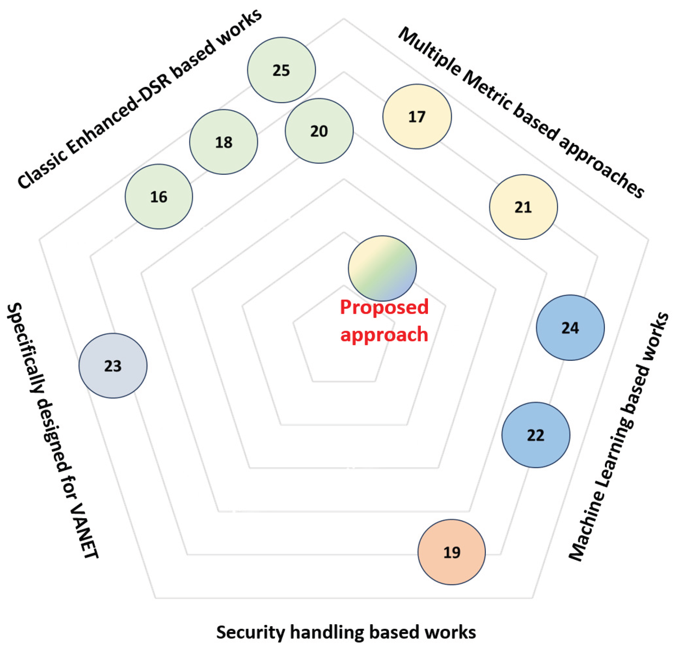
Figure 1. Proposed approach direction compared to related works.
Preprints 112183 g001
Figure 2. Architectural Overview of MMS-DSR.
Preprints 112183 g002
Figure 3. Network topology diagram illustrating the routes from Node A to Node J with respective metrics.
Preprints 112183 g003
Figure 4. Network topology diagram illustrating the routes from Node A to Node J with respective metrics.
Preprints 112183 g004
Figure 5. CNN-LSTM model architecture for MMS-DSR.
Preprints 112183 g005
Figure 6. Flowchart of the CNN-LSTM Data Processing for MMS-DSR.
Preprints 112183 g006
Figure 7. Schematic of CNN-LSTM Integration into MMS-DSR.
Preprints 112183 g007
Figure 8. Network topology diagram illustrating the routes from Node A to Node J with respective metrics.
Preprints 112183 g008
Figure 9. Network topology diagram illustrating the routes from Node A to Node J with respective metrics.
Preprints 112183 g009
Figure 10. MMS-DSR UML considered scenario.
Preprints 112183 g010
Table 1. List of main Symbols and Acronyms used in the paper.
Symbol Description
α Weighting factor for the summation real-time term
λ Weighting factor for the beamforming score
δ Weighting factor integrating the predictive reliability score
w i ( t ) Time-dependent weights
m i ( r ) Route metrics for MANET
v i ( r ) Route metrics for VANET
P p r e d i c t i o n ( r , t ) Predictive reliability score
B F ( r , t ) Beamforming score
L ( r , t ) Latency
B ( r , t ) Bandwidth
R ( r , t ) Reliability
B ( r , t ) Bandwidth
B E ( r , t ) Beamforming efficacy
D e ( r , t ) Vehicle density
D i ( r , t ) Vehicle distance
T ( r , t ) Vehicle trajectory
S ( r , t ) Scoring function
T N V A Total Number of Vehicles in the Area
A S Area Size
d i Euclidean distance of vehicle from the destination
d ref Reference distance
ζ Attenuation factor
d ( t ) ζ Future distance of the vehicle in the route to the destination at time t
d ( 0 ) ζ Current distance to the destination
J ( w , t ) Cost function
m ^ i ( r , t ) Predicted value of the metric
S Real-time measured data matrix in input into the CNN
X High-level spatial feature map output by the CNN
w t filter with K L + 1 coefficients
b t bias term
f l l t h activation function
convolution operation
F High-level spatial feature map in input to LSTM
H Spatio-temporal features output by LSTM
M Adjustable input window size
T Adjustable ouput window size
W * , F , W * , H Weighting matrices for current input high-level spatial feature matrix F n and previous spatio-temporal feature matrix H n 1
DSR Dynamic Source Routing
MMS-DSR Multi-Metric Scoring Dynamic Source Routing
SOL-DSR Self-Organizing Learning Dynamic Source Routing
OLSR Optimized Link State Routing
RSU Road-Side Unit
MU-MIMO Multi-User Multiple Input Multiple Output
OMNeT++ Objective Modular Network Testbed in C++
SUMO Simulation of Urban MObility
Disclaimer/Publisher’s Note: The statements, opinions and data contained in all publications are solely those of the individual author(s) and contributor(s) and not of MDPI and/or the editor(s). MDPI and/or the editor(s) disclaim responsibility for any injury to people or property resulting from any ideas, methods, instructions or products referred to in the content.
Copyright: This open access article is published under a Creative Commons CC BY 4.0 license, which permit the free download, distribution, and reuse, provided that the author and preprint are cited in any reuse.
Prerpints.org logo

Preprints.org is a free preprint server supported by MDPI in Basel, Switzerland.

Subscribe

© 2024 MDPI (Basel, Switzerland) unless otherwise stated