1. Introduction
In the current energy market, the focus on limiting environmental pollution, particularly greenhouse gases, has prompted the need for modern design standards in conventional power systems. Depletion of fossil fuel reserves and notable power losses have increased the reliance on Renewable Energy Sources (RESs), including PV and Wind Generation S (WG), in traditional grid frameworks[
1,
2]. The MG operations primarily focus on integrating local loads in the distribution network to enhance Power Quality and system reliability. Distributed Generations (DGs) encompass converter stations and associated components, ensuring stable and reliable power dispatch. DGs serve as alternatives to traditional electricity generation methods, offering a range of scientific options from RE & non RE sources. These systems can operate in on-grid or off grid modes, providing flexibility and resilience to the power infrastructure. Renewable energy-based DGs effectively alleviate power crises in central grid buses. Leveraging various sources such as solar photovoltaic, wind generation, fuel cells and (CHP) systems, biofuels, and micro-turbines, DGs offer advantages for small-scale localized grids. These include reduced carbon emissions, long-term asset viability, dynamic power regulation, and suitability for rural applications, making them invaluable contributors to sustainable energy solutions. The countries like India where there are abundant sunlight is available, is suitable for solar production. Now India has become stronger in solar power generation and PV infra-structure.
PV-based DGs are extensively documented in literature [
4,
5,
6], conforming to IEEE 1547 standards, requiring capability for both grid interactive and islanded modes [
4]. As suggested in [
5,
6], the control Hierarchical structures for effective management of PV-based DG systems. ISA-95 standards endorse hierarchical structures for distribution-level PV DG solutions, such as Rooftop PV installations, facilitating coordinated distributed control. By this application PV operates at maximum power points with MPPT algorithm [
7,
8,
9,
10]. The conventional MPPT control algorithm like P&O. INC and Hill climbing are best suitable in simplicity and low operational cost. However they are not good performer in partial shading conditions [
7]. Other methods like Fuzzy based MPPT needs pre requisite information and have high computational burden [
8]. On the other hand artificial neural network (ANN) based MPPT has high speed computation and well performed in shading condition [
9].However, ANN's learning architecture, such as feedback bias, hinder its adoption in small-scale PV solutions. Following ISA-95 standards, the ordered controller comprises a Primary Controller (PC) and (IDGCs). In managing Distributed Generation (DG) systems, Control References (CRs) are crucial for effective energy management. To achieve this, Integrated Distribution Grid Controllers (IDGCs) function as closed-loop feedback controllers, overseeing Converter stations on the PV side. These IDGCs employ duty cycle calculation for PV-DC operation and (PWM) based (PLL) operations, ensuring coordination within distributed PV systems while adhering to standardized protocols. In PV-based DG applications, cost-effective solutions are paramount for managing local loads. Integration of Independent DG Controllers, encompassing (MPPT) tracking and feedback control for duty measurement, is vital for stability analysis. To tackle computational complexity, Artificial Neural Network (ANN) based control algorithms offer a promising avenue. Here, solar irradiation (W/m2) and PV panel temperature (°C) serve as control inputs, while duty reference for DC Voltage Boost operation is the output. This optimized approach, implemented every
iteration with a computational clock time constant (
intervals), streamlines computational burden while enhancing accuracy in CRs calculation. Consequently, it ensures the efficient operation of PV-based DG systems, mitigating computational overheads, and maintaining stability.
As discussed in [
17] a novel deep representation-based (MPPT) controller for precise Control references calculation in Photovoltaic (PV) based Micro Grid (MG) operation. The approach involves a two-step estimation process: Data dimension reduction and MPPT Tracker optimization for efficient computation. Targeted for a large number (N) of PV-based DGs locally connected in the distribution system, the method utilizes Extreme Learning Machine (ELM) for data dimension reduction and Ridge Regression-based ELM for MPPT error estimation at the Tertiary Control side.
The standard power recognizing controllers may localize the functioning point of PV rather than capturing the global working point as depicted in the literature. The conventional neural controller depicted in[
9] requires substantial expertise in static analysis and calculus, along with extensive training and loading data. Neural designs consist of interconnected neurons organized in multiple layers, with biological neurons represented as nodes. Data processing occurs from the input layer to the output. Similarly, multilayer power point finding controllers incorporate multiple hidden layers, leading to increased implementation complexity and high computational time.
In [
18,
19,
20,
21,
22], authors propose a soft computing approach using fuzzy logic to track MPP variations in solar PV systems. They introduce a variable step radial basis functional controller fused with fuzzy logic to improve upon conventional fuzzy controllers in partially shaded conditions. This hybrid controller combines the strengths of fuzzy logic and artificial neural networks (ANN) to optimize MPPT. While fuzzy logic and ANN methods are effective, they can be computationally burdensome. Integrating these methods offers a robust solution to nonlinear problems, enhancing MPPT efficiency in challenging conditions. To overcome the challenges from fuzzy and ANN based MPPT controller, This paper introduces a streamlined approach using a single-layer, feed-forward (ELM) to enhance computation time efficiency.
Here the online sequential learning method with Ridge Regression Regularization, is applied to optimize the training output weights for ELM-IDGC. Motivation and problem formulation and literature survey are discussed in section-1. Section-2 describes the architecture of PV based micro grid with detailed specifications. This section also covers boost operation with linear PI control based duty measurement. The ELM-based IDGC operation is outlined in section 3, emphasizing online training methods.
Section 4 validates the performance of this control approach, presenting MATLAB-based results that demonstrate improved stability with the proposed ELM-IDGC. Finally, section 5 offers an overall discussion and summary of the research findings.
3. Proposed DG Controller
The (IDGC), integrating MPPT and closed loop PI control for duty assessment, can benefit from a computationally efficient approach using Artificial Neural Network (ANN) based algorithms. Input parameters such as solar irradiation and PV panel heat , with output as duty reference for DC boost operation streamline computations by directly converting , to, omitting intermediate steps like, and . This reduction in calculations per iteration, enhances accuracy in calculating Control References (CRs).
To address the limitation of ANN-based IDGCs in real-time feasibility due to weight matrix estimation, a non-iterative Moore-Penrose Pseudo-inverse
technique is employed for training. This technique, unlike conventional iterative methods, such as back-propagation, enhances efficiency and is applied to feed-forward ANN like (ELM) [
9].
In
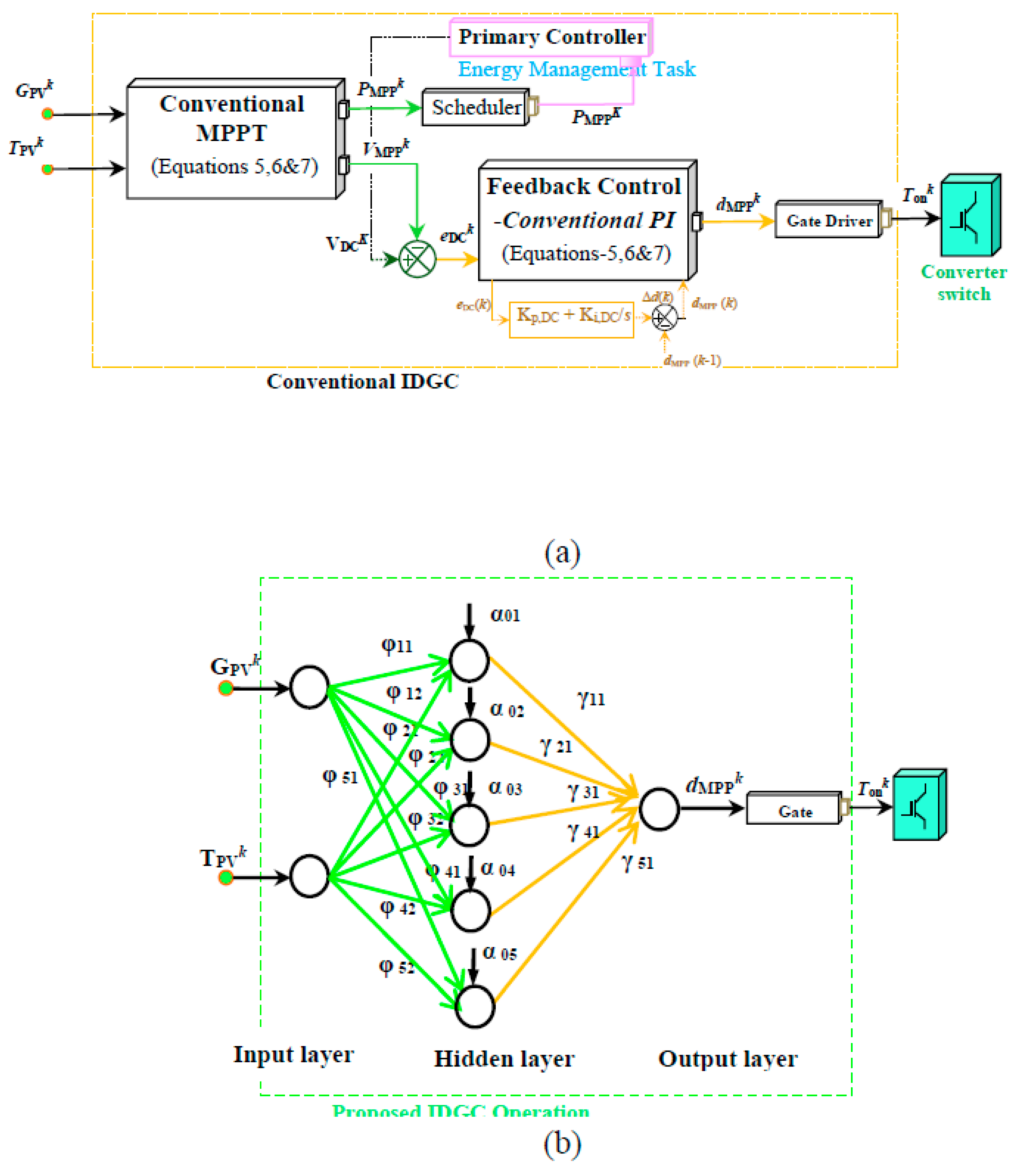
Figure 3 (a), the traditional IDGC (following ISA-95 standard) involves two-step duty cycle designs, prone to Control Reference (CR) errors, potentially compromising DC bus stability. In Contrast, the proposed ELM-IDGC (
Figure 3(b) streamlines computational steps and minimizes iterative learning, reducing computational delays. The fast, learning approach (MPPi) is advised for the ELM-IDGC, aiming to enhance stability. The linear relationship between duty cycle
and MPP voltage (VMPPk) depicted in Fig. 3 indicates predictable behavior. Variations in irradiation yield different
(Figure 3a) and
(
Figure 3b). By leveraging linear functionality instead of non-linear nodes, the proposed IDGC anticipates improved stability. The ELM learning strategy is poised to swiftly and robustly reduce errors.
In ANN literature, numerous constructional and working enhancements are explored, ranging from basic feed-forward structures to complex architectures incorporating feedback bias. Operational methods span from traditional back-propagation and least square solutions to contemporary non-iterative (NI) techniques, enriching control algorithms' operational perspectives [
9].
3.1. Redge Regression Based ELM
ELM has gained prominence as a feed-forward neural network (FFNN) in the past decade [
23]. Because of its straightforward construction, different training techniques, such as least-square solutions, are recommended for strong valuation of error reduction. In PV-based DG applications, literature predominantly focuses on either MPPT algorithms alone or feed-forward IDGC structures, where
and
are functions of
derived from linear MPPT data. However, adhering to ISA-95 and IEEE 1547 standards (
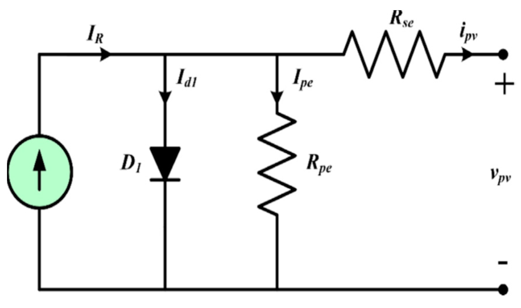
Figure 2a), the entire operation, including traditional two-step MPPT tracing and closed-loop duty assessment, must be employed at the IDGC level. Hence, trained data for the proposed IDGC is acquired according to normal performs.
The structure of ELM comprises Input, Hidden, and Output Layers (
,
&
) respectively, to derive preferred probable Control References (CRs), such as
(
Figure 2b). Table 2 presents common notations for clarity. The general ELM is single-layered, and training employs a ,
inverse method [
24]. IL nodes connect with arbitrary
, while [γ] is derived from non-iterative training. In spite of arbitrariness, ELM can be designed with minimal
during training, outperforming conventional techniques. Unlike methods requiring both [φ] and [γ] from initial randomness in training, ELM exhibits improved generalized performance.
The Input layer node is given by
And the output layer node is presented as
Here A and B are input & output data size.
The hidden layer matrix is expressed as
Initially,
is arbitrarily chosen from 0-1 during training. The sine hyperbolic activation function is employed for its adaptability to large
signatures. Post-training, estimated CR:
is derived from the output layer node for real-time performance.
The
is utilized for finalizing the
[ γ ] C×B with training data samples as:
During supervised learning, the OL layer outputs for training samples, with a minimization formulation.
The Regularization coefficient is measured from [
14].
are the usual abreviations like input weights, hidden layer output matrix output weight, bias in output layer.
, are the regularisation and control reference error.
3.2. Robust Estimation Enhanced via Online Learning, Refining Models Dynamically for Resilient Data Analysis and Accurate Parameter Estimation
Dynamic control enactment necessitates a state inform agenda to maintain balanced working conditions in PV DG applications. The ELM-based IDGC is trained via online sequential learning, where training data isn't entirely processed upfront. Instead, successive gaps (N data chunks) are treated iteratively, enhancing adaptability to changing conditions and facilitating real-time adjustments for improved performance.
In connection with input layer node,
and output layer node
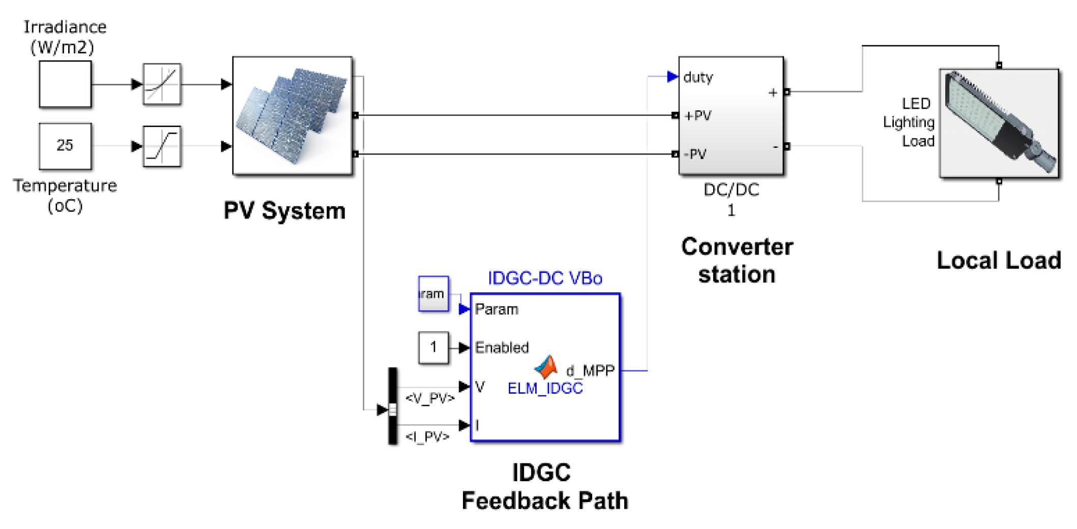
the ELMIDG is operated with PV-DG as shown in
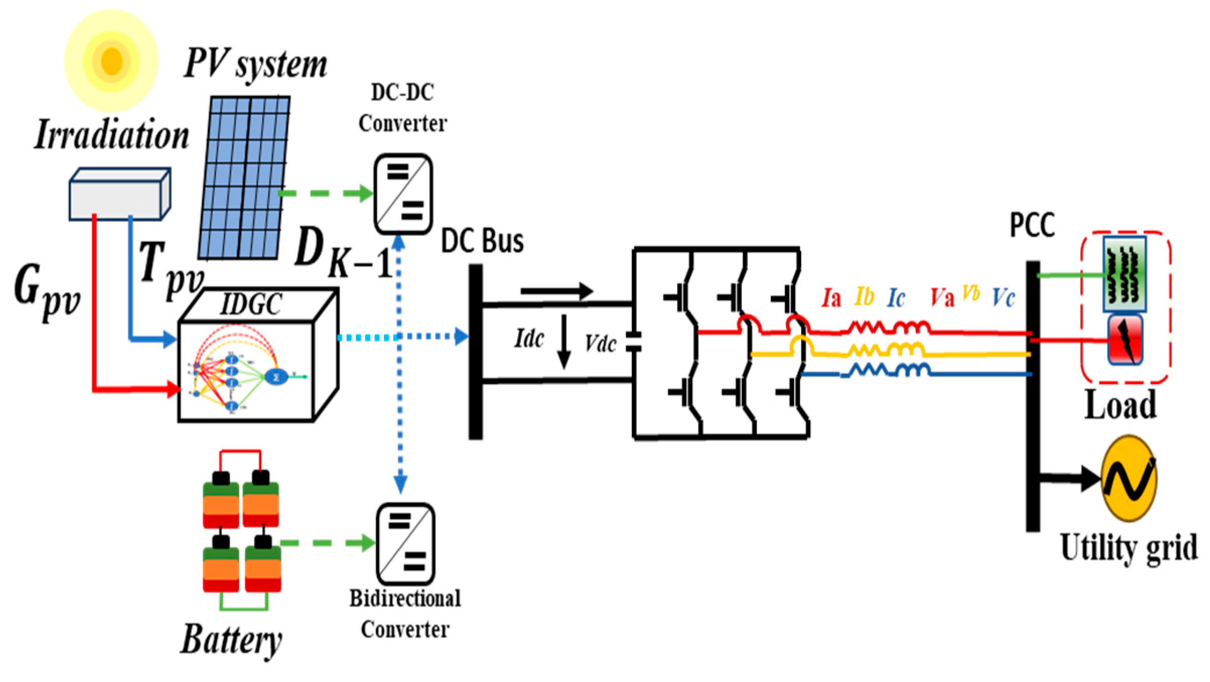
Figure 1. To improve the training performance of
optimal with error
reduction, the online sequential learning is applied.
4. Result Analysis
Here a single DG based Micro Grid is designed in MATLAB/SIMULINK platform. The model details are given in this section. The proposed ELM-IDGC controller has been applied to a 10 kw PV application. The model is simulated for 10, 40 60 seconds and the results are compared with the conventional method.
The enactment is evaluated through various operating conditions like MPPT error minimization, Irradiance change, partial shading, islanding operation three phase fault and load change. The Micro Grid parameters are 12 kW, 100volt DC, dc link voltage 150 V (DC), 230 V, 50 Hz AC conversion and load rating is 10 kW, 0.784Ω LEDs. Converter to PCC impedance is 2km ohm.
Senario-1: MPPT Error minimization
During the operation the accuracy and computational burden are two major parameters to be measured. The efficacy of the proposed MPPT model is compared with the traditional linear & nonlinear techniques. Solar irradiance and the panel temperature are the two major input data to the MPPT. The RES data set is divided into different sets based on the seasons. During considered events like partial shading the seasonal data is resampled for RES-
PPV and
VPV estimation, with the uncertainty. The training and testing ratio of irradiance data is 7:3. Various performance matrices are described to estimate the MPPT error, which are formulated as following.
Here total samples is ‘N’ and Pk and Tk are actual value and predictable value of the MPPT.
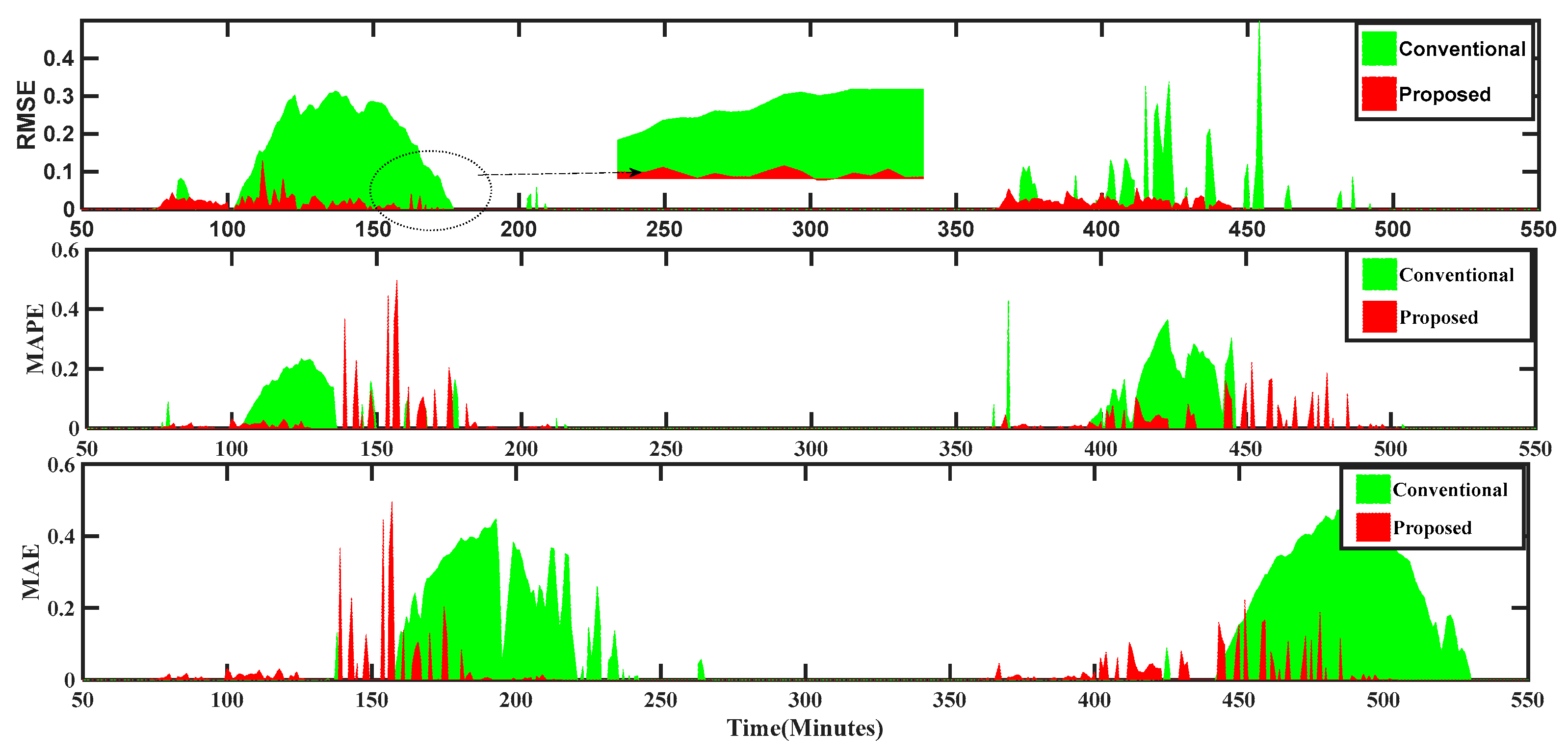
From the DAS data validation and the PCC of Micro Grid parameters, the performance of the proposed MPPT is judged. The DAS data with 5 minutes interval measures various error responses such as RMSE, MAPE. For long time interval the MPP will be erroneous for which 5 minutes interval is considered. Here the proposed ELM based IDGC has been implemented to estimate maximum power in a Micro Grid. Its performance is compared with basic MPPT controller. The entire PV data is classified into different seasons and here only summer data profile is validated.
Figure 5 depicts RMSE 0.061% - 0.88% and MAPE 2.48%-4.48%. The RMSE of conventional & proposed are given in Pu 0.032-0.0038 respectivelly.The range of MAPEs in Pu are 0.0412-0.0622 and 0.1053-0.2348 conventional and proposed ELM respectively. It is evidently proved that proposed MPPT performs effectively better than the conventional MPPT.
Scenario-2: Performance under Irradiation Variation
The PV generated voltage and power is affected by the solar irradiance change, due to its intermittent nature. The irradiance depends upon the weather conditions. In sunny weather the substantial amount of irradiance is produced and the PV generates its rated power and voltage. But in rainy season and foggy weather the PV generation is affected. To compensate this challenge a battery energy storage (BES) is connected to the system. The intermittent nature of irradiance influence the DC link voltage and other parameter of MG also. The presentation of the proposed controller is investigated during irradiance variance through AC bus parameter disturbance. The fault clearance time is measured in seconds and cycles. The performances are listed in table-2. From the
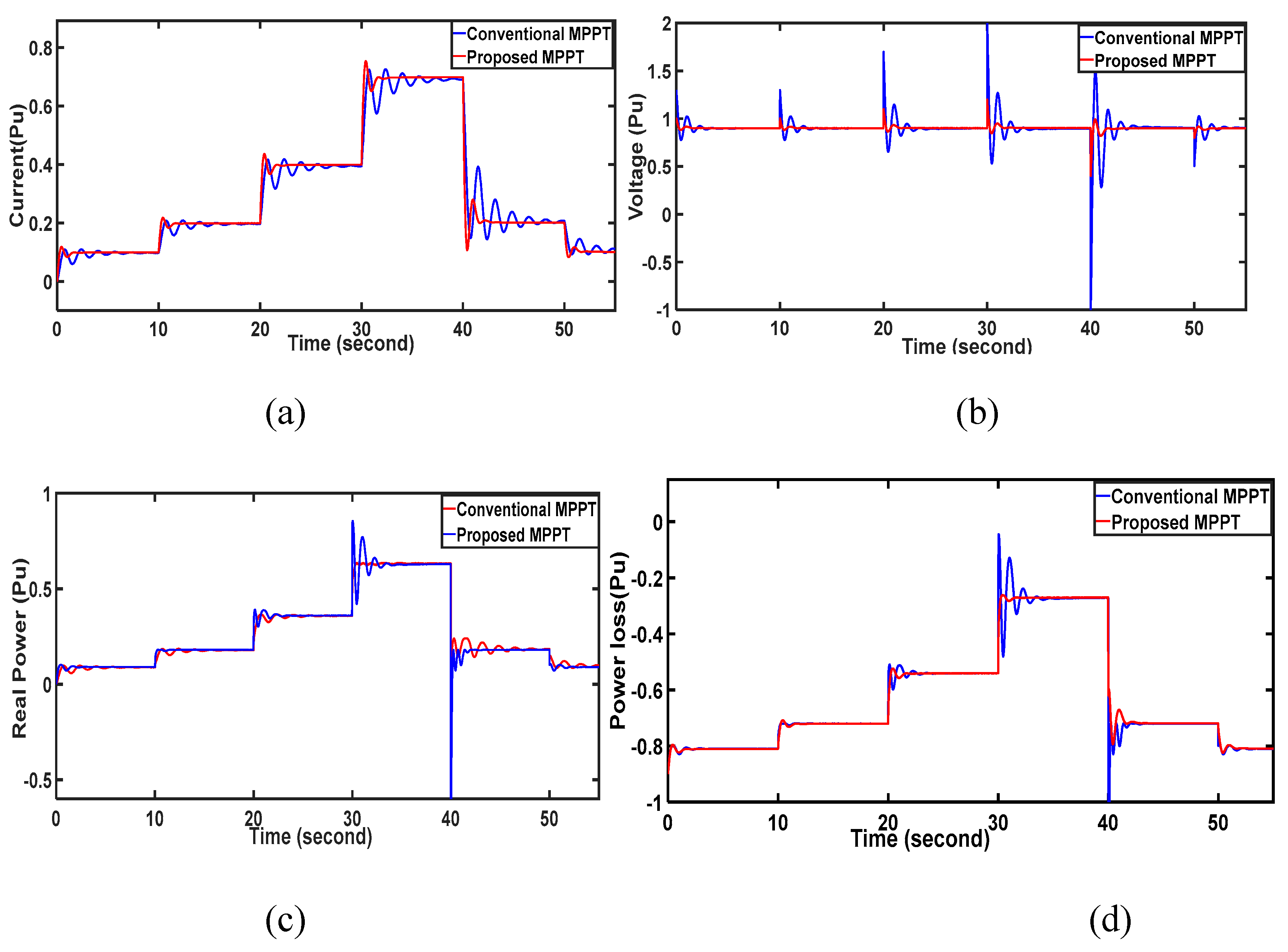
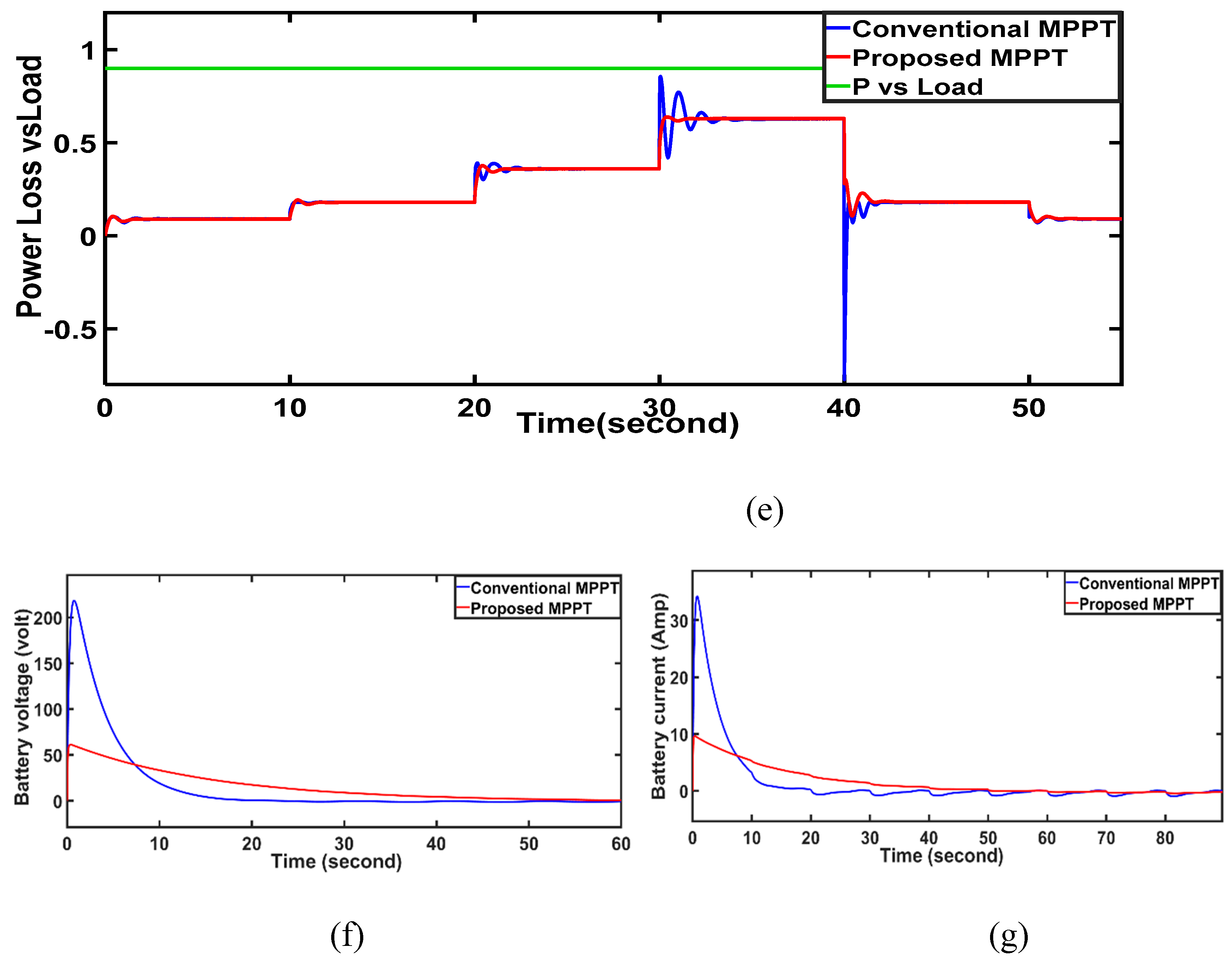
Figure 6, it is observed that the irradiance changed in three states. In each state the fault mitigates 1 second (50 cycles) but the conventional MPPT mitigates the fault in 10sec (200 cycles) in each state. The PV and IV charectestics of the PV cell is shown in
Figure 6a,b respectively, during various states. The instability created in the MG is balanced by auxiliary power supply by the battery system given by the equation (17)
Figure 6f,g, displays the battery voltage and current fluctuations amidst irradiance changes, showcasing the superior performance of the suggested IDGC over conventional methods. The Proposed method exhibits minimized power oscillation and transient variation during fault incidents. This confirms IDGC superiority in managing system dynamics, offering improved stability and efficiency compared to traditional techniques.
Table.
comparisons of MPPT controller with 3 states.
Table.
comparisons of MPPT controller with 3 states.
| MPPT Technique |
State-1 |
State-2 |
State-3 |
| Voltage ripple (V) |
| Conventional |
3.98 |
2.87 |
3.88 |
| Proposed |
0.08 |
0.04 |
0.03 |
| Current ripple (A) |
| conventional |
0.93 |
0.49 |
0.054 |
| Proposed |
0.35 |
0.26 |
0.003 |
| Convergence time (s) |
| Conventional |
0.051 |
0.042 |
0.045 |
| proposed |
0.0062 |
0.0084 |
0.003 |
| Tracking Efficiency (%) |
| Conventional |
96.98 |
96.92 |
97.10 |
| Proposed |
99.2 |
99.32 |
99.91 |
| Overall efficiency |
| Conventional |
94.93 |
92.85 |
91.51 |
| Proposed |
97.93 |
97.83 |
97.81 |
| RSME MPPT Error |
| Conventional |
0.00481 |
0.02471 |
0.03166 |
| Proposed |
0.00061 |
0.00181 |
0.00287 |
| MAE Error |
| Conventional |
0.00561 |
0.02971 |
0.01861 |
| Proposed |
0.00049 |
0.00187 |
0.00297 |
| MAPE Error |
| Conventional |
0.5289 |
2.831 |
4.105 |
| Proposed |
0.0812 |
0.198 |
0.536 |
Scenario-3: Partial shading
To achieve the rated power for a Multi-Panel Photovoltaic System (MPVS), the arrangement of PV panels in series and/or parallel configurations is crucial. Series connection boosts the output voltage, while parallel connection increases the PV array output current. Accurate modelling of the PV array, necessitates reproducing the actual current-voltage (I-V) characteristic curve of the PV cells. In literature, single and double diode models are commonly employed. The single diode model, simpler and less computationally intensive, is often favoured, particularly for demonstrating partial shading effects, offering satisfactory results with minimal complexity.
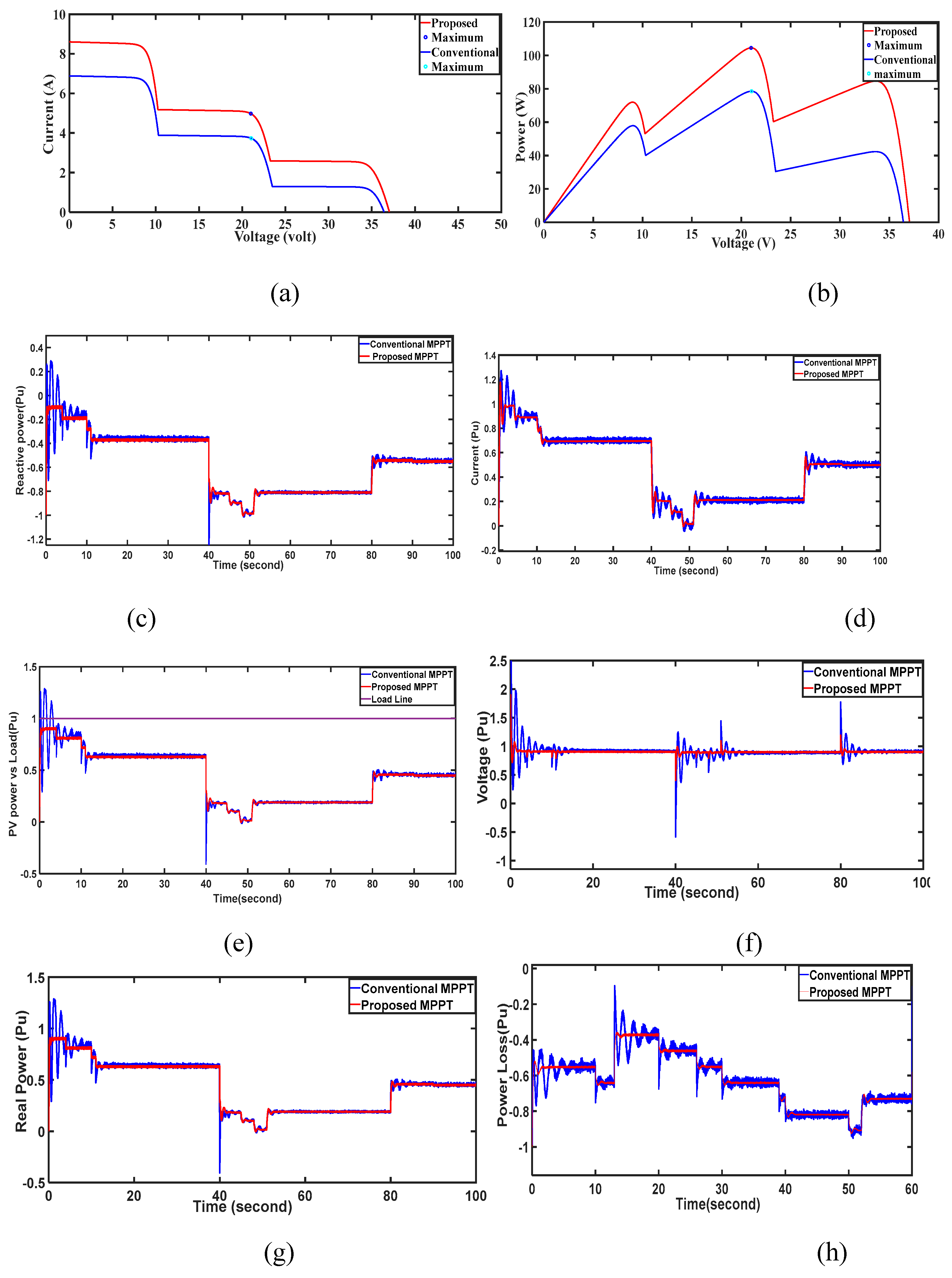
Under non-uniform irradiation, the power-voltage (P-V) characteristics of the PV array exhibit multiple peaks as shown in
Figure 7a,b. The highest peak, termed the global maximum point (GM) and lowest is local maximum points (LM). The number of peaks correlates with the number of panels receiving varying power or irradiance levels, while the position of the GM depends on the intensity of irradiance and the arrangement of panels.
In this case a multi cell PV array is used as distributed generator of a MG. A 100 watt PV panel is taken with total 60 cells (connected 40 series and 20 parallel). As depicted in
Figure 7, the partial shading is achieved by disconnecting individual cells. Here each cell is of 0.15volt and 1.5 watt. At t=5 sec, 2 cell (3 watts), at t= 10, two cells (3 watt) and at t= 40sec to 50 sec, 6 No of cells (0.9V, 9 watts) are disconnected. Further at t=80 sec two cells (0.3volt, 3 watt) are included. The disconnection of cells results the partial shading operation of PV module. The Cell reduction produces a disturbance in PV output and Micro Grid System. By this types of disturbance the DC voltage fluctuates by 2.5 Pu, approximately. Current fluctuated within 0.4 Pu. Similarly the deviation of real power, reactive power and active power loss by both MPPT controllers are shown in
Figure 7. From the results it is confirmed that the proposed IDGC MPPT controller reduces the deviations quickly than the conventional controller.
Scenario -4: Three phase fault at Bus-1
The efficacy of the system with increased strength undergoes scrutiny in a three-phase fault scenario at bus-1 (PCC).
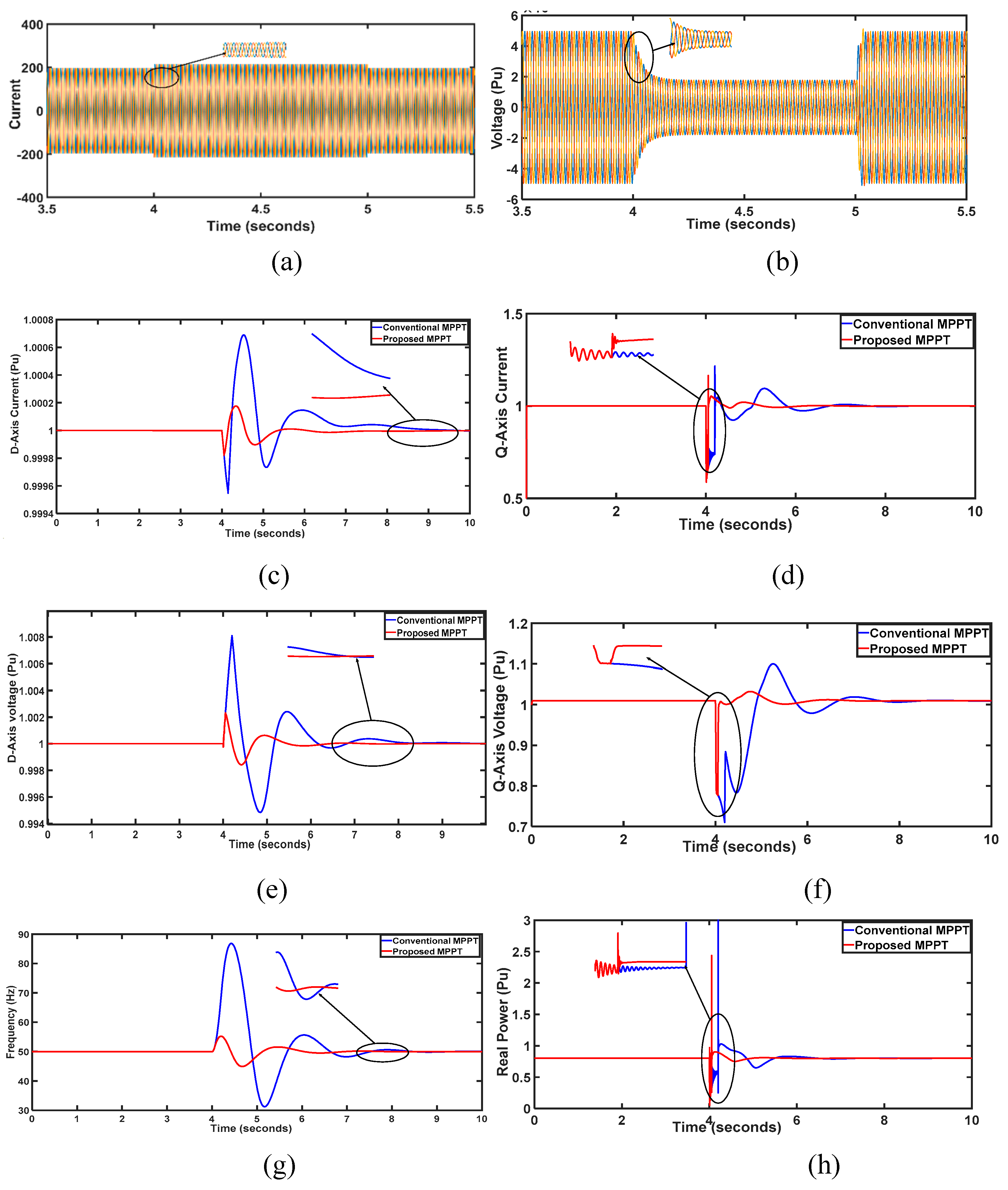
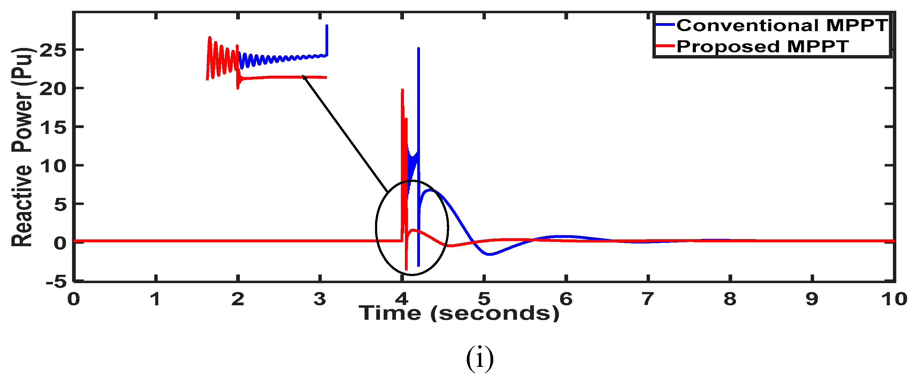
Figure 8, illustrates the response of various grid and auxiliary power supply parameters. At t = 0.5 s, a five-cycle three-phase fault is introduced at the PCC. The IDGC technique swiftly damps oscillations, stabilizing the system within 2 seconds or 100 cycles. In contrast, conventional MPPT requires nearly 4 seconds (200cycles) respectively, for system restoration post-fault occurrence. Fig--- depicts the DC link voltage between the PV system's back-to-back converters, revealing notable stability with the proposed technique Figure---. Convergence of the cost function is achieved in merely 9 iterations with the proposed IDGC. Optimal gain parameters yield reduced transients and an optimally responsive system. Overall, the proposed approach ensures efficient system stability and rapid response during fault scenarios, outperforming traditional methods in both damping capability and convergence speed. Further the results depicted in
Figure 8, the direct axis voltage and current have been simulated. Three phase fault sustains for 1 second (4sec to 5 sec). In all the following simulation results the Conventional MPPT controller settles the system in 4second whereas the proposed IDGC technique achieves steady state condition in 1 second. Thus the proposed IDGC proves its superiority than the conventional MPPT controller in overshoot and settling time.
Scenario-5: Islanding Operation
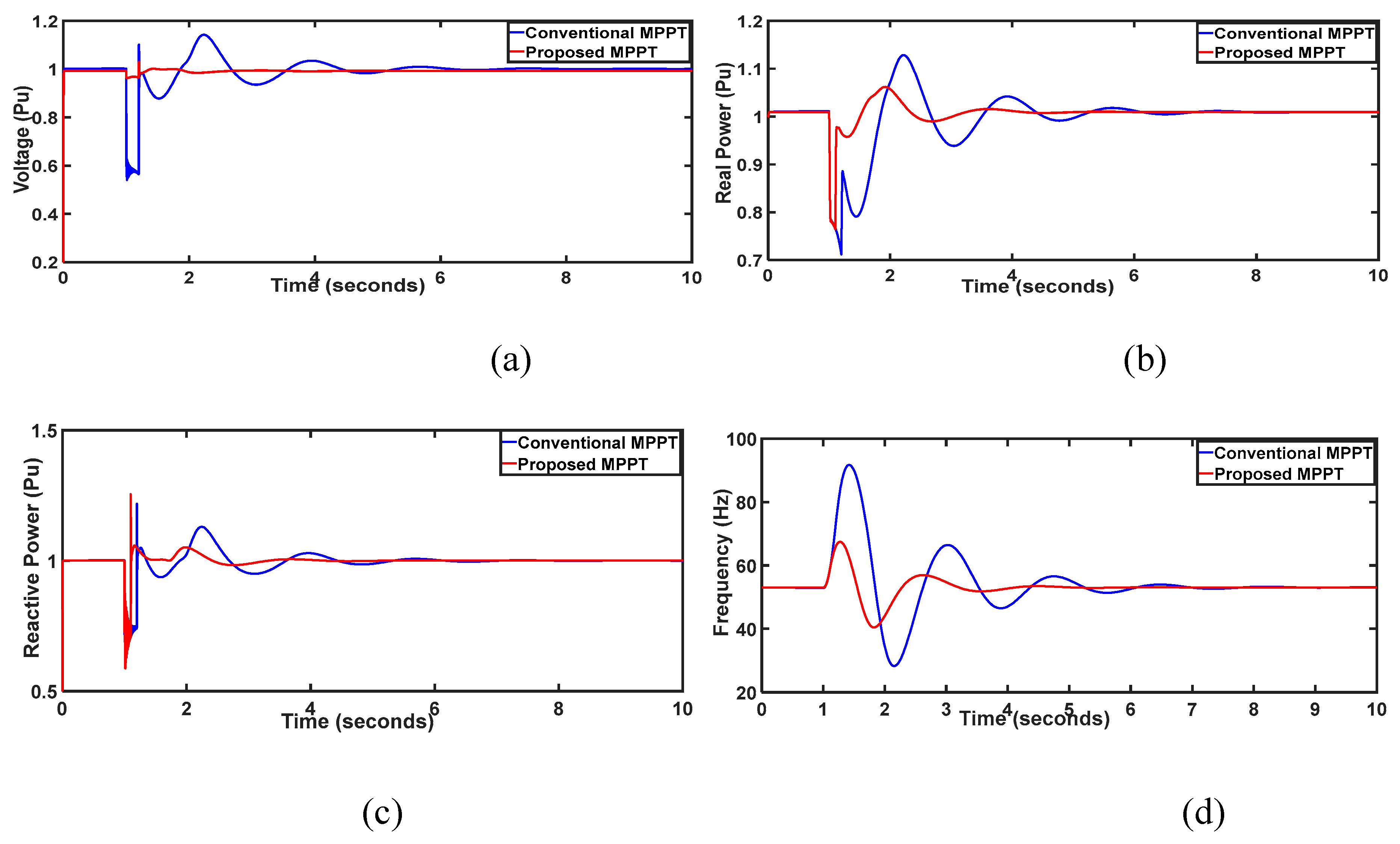
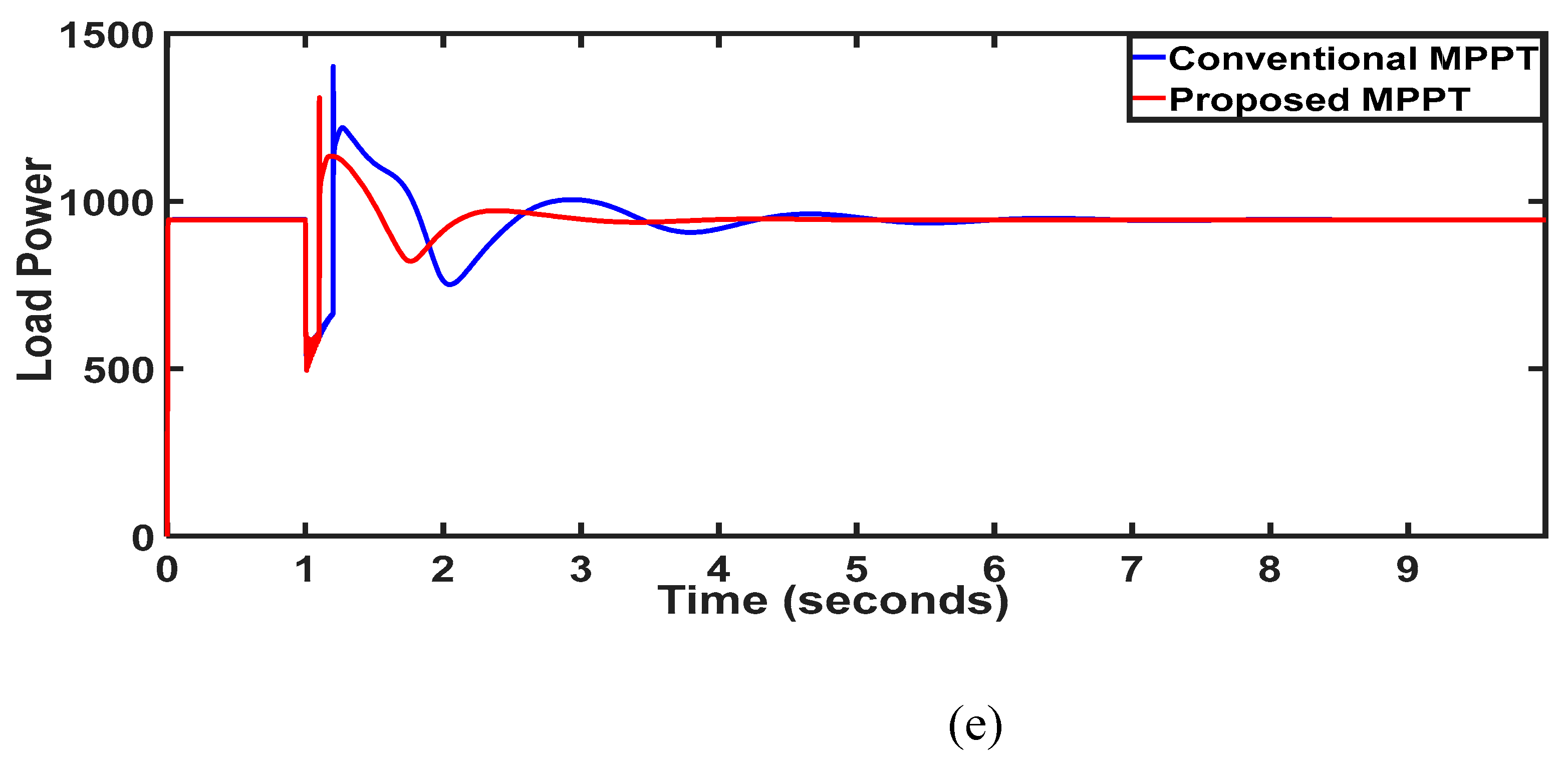
The Micro Grid behaviour is investigated with the proposed controller during islanding situation. At t = 1 s, intentional islanding is initiated via switch s1, as depicted in Fig.-9, focusing on the responses of PCC parameters. During islanding, the combined output from PV and battery adequately meets local load demand, ensuring stable bus-1 voltage through Distributed Generation (DG) supply amidst uncertainties. Notably, the proposed IDGC controller achieves system stabilization within a swift 0.5-second span, equivalent to 25 cycles (
Figure 9a). In comparison, alternative methods require more cycles: the conventional MPPT controller-based Phase-Locked Loop (PLL) controller demands 100 cycles (2 s); the proposed controller exhibits heightened damping, resulting in diminished transient oscillations. Fig- Illustrates convergence graphs of optimization methods, showcasing the proposed controller's rapid convergence (merely 5 generations) with minimal error content. This underscores the efficacy of the proposed approach in swiftly stabilizing the system during intentional islanding, outperforming conventional methods in both convergence speed and transient response.
Scenario-6: Load Change:
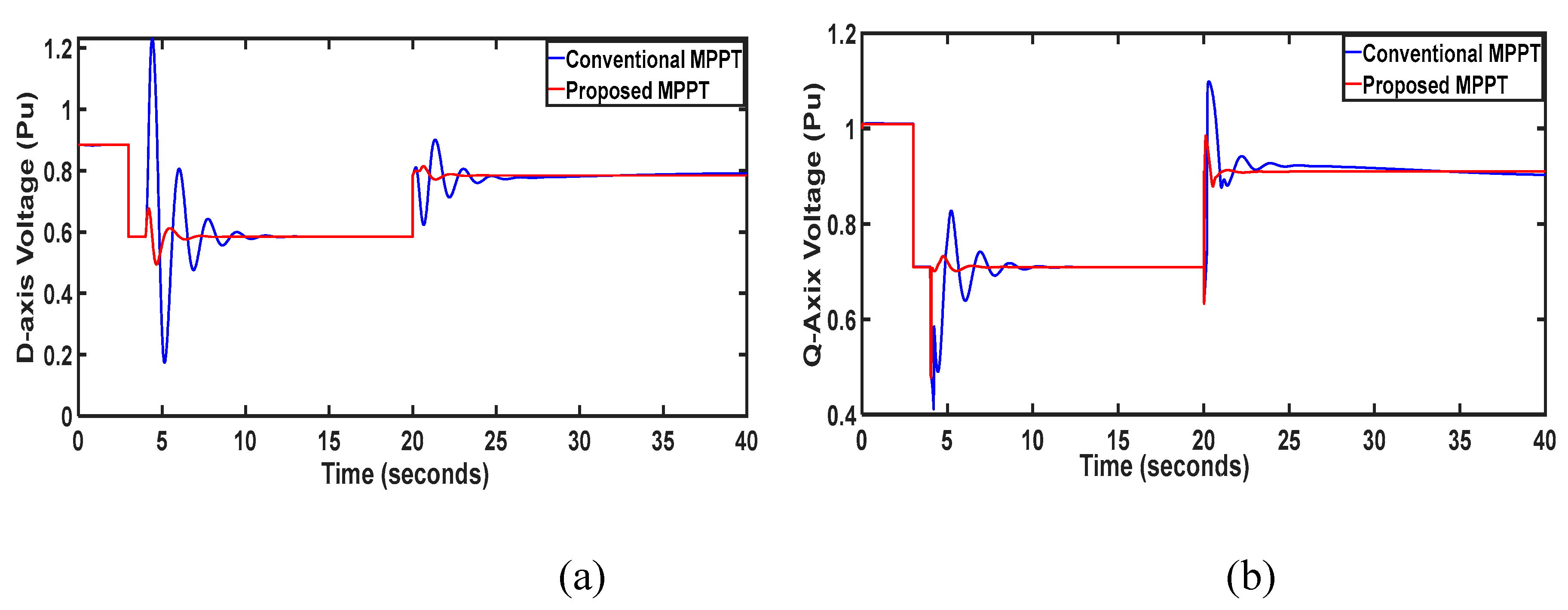
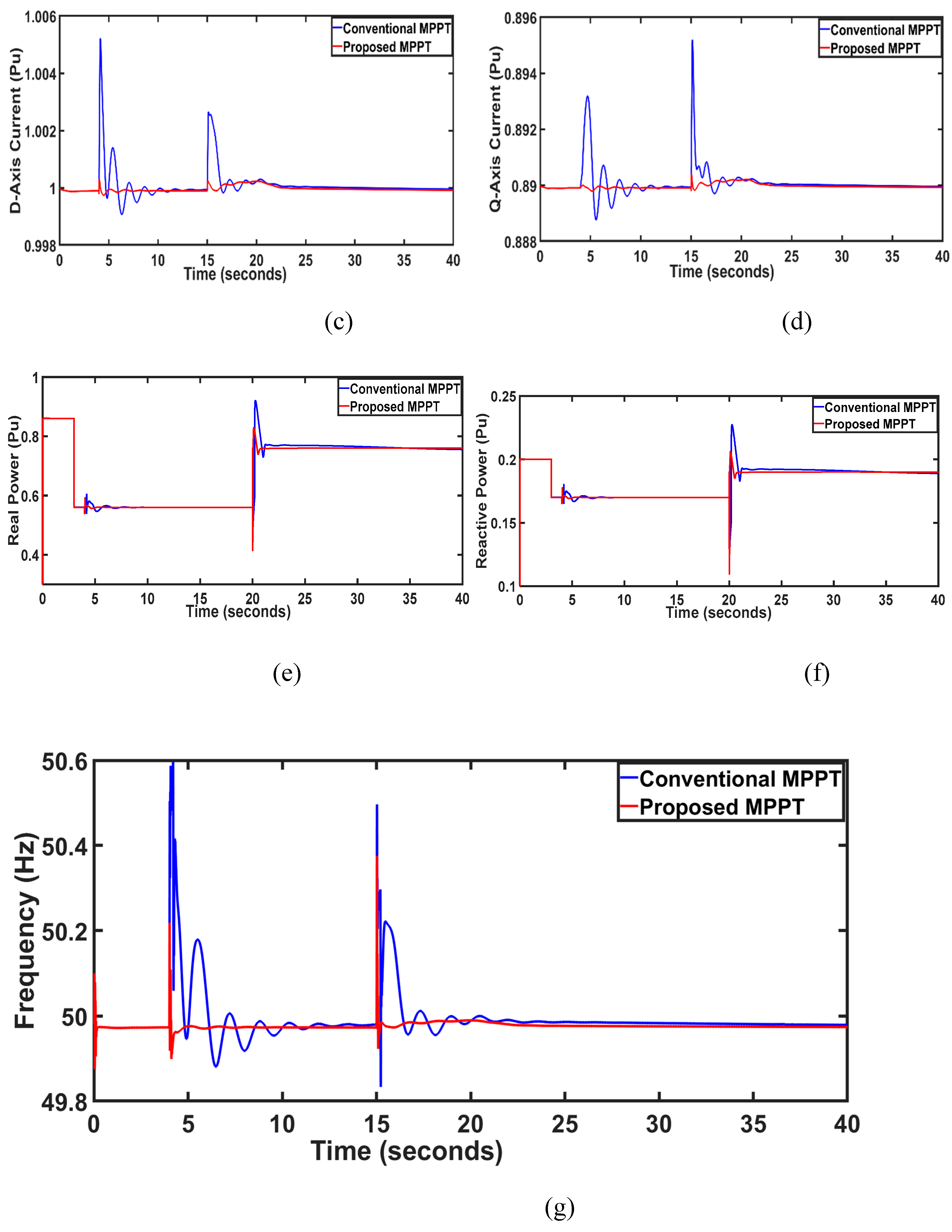
The performance evaluation extends to variations in load parameters, specifically at (PCC), where a 30% decrease occurs at t = 5 s followed by a 10% increase at t = 20 s, as depicted in
Figure 10. The load current, as illustrated in
Figure 10c,d, exhibits a corresponding decrease and subsequent increase in line with the load variation. Notably, despite these fluctuations,
Figure 10a,b showcases the remarkable constancy of bus-1 voltage, indicative of effective controller operation, resulting in minimal deviation. Conversely,
Figure 10e,f reveals the real and reactive power trend opposite to that of load current. The system's restoration time with the proposed IDGC controller stands at a mere 25 cycles (0.5 s), a notable improvement compared to the conventional technique requiring 50 cycles (1s). Furthermore, transient oscillations are notably subdued in the proposed method compared to the conventional techniques. Employing optimal IDGC method results in a system exhibiting superior transient profile and optimal functionality. The combination of reduced restoration time, minimized transient oscillations, and swift convergence of optimization underscores the effectiveness of the proposed approach in enhancing system stability and performance amidst load variations, offering significant advantages over conventional methods.
Scenario-7: Hardware Validation
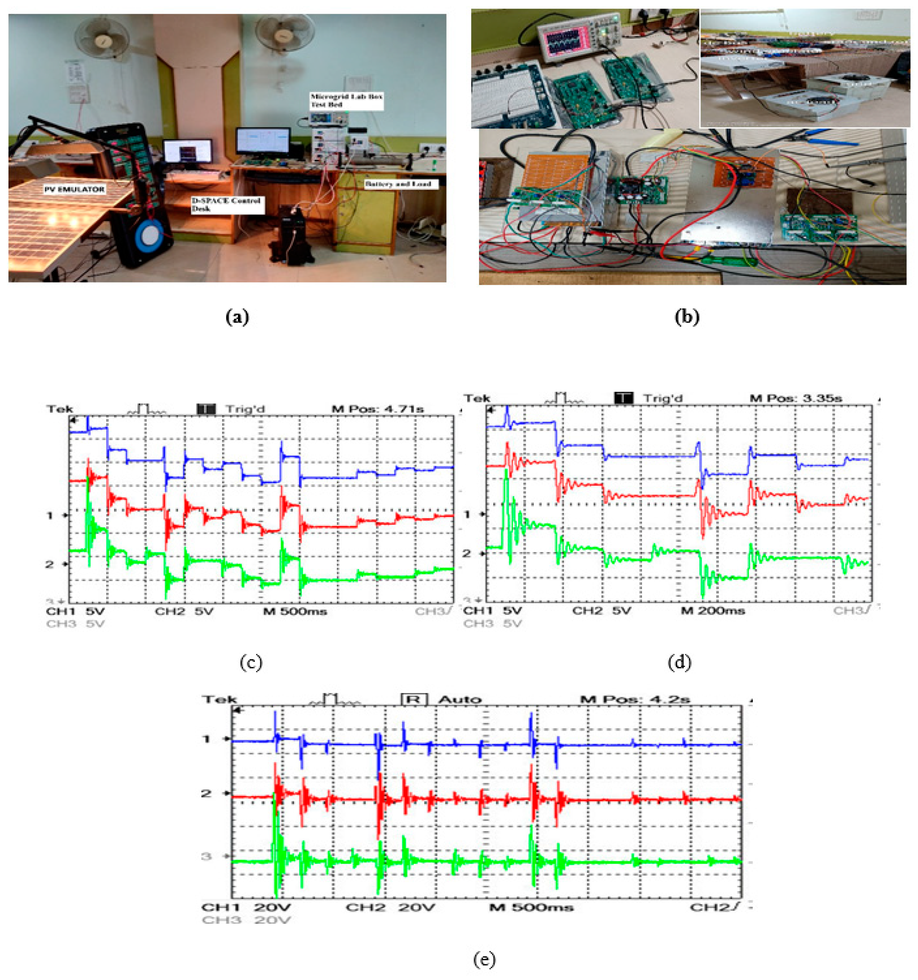
The validation of the performance of the proposed IDGC in a micro grid involves a Hardware-in-the-Loop (HIL) simulation. In this setup, the system, comprising a standard model with solar PV and battery energy storage (BES), is simulated using MATLAB Simulink. The PV-based DG is emulated using a PV emulator, specifically the Prototype solar plant, interfaced with Simulink as a 'Controlled Voltage Source'. Real-time data, including irradiation variation and partial shading, are captured through a dSPACE 1104 extension boards (ADC C5: DS1104 Master PPC library).
The performance of the PV bus (PCC) is monitored by recording its RMS voltage & current, as depicted in
Figure 11. To optimize the system's performance, controller gains are tuned using MATLAB script-based analysis and then implemented in the Simulink model. The irradiation profile for the PV is varied at specific time intervals, and data acquisition is facilitated by a digital-to-analogue converter (DS1104 C1 from DS1104 Master PPC library) connected to a TMS 320C6713 digital signal processor via Embedded USB JTAG. The collected data are visualized using a digital storage oscilloscope (DSO) (Tektronix TBS1022) through a Toshiba TLP 250 gate driver.
The conventional MPPT resulted in erroneous performance, manifesting in 150 cycles of dynamic oscillation. However,
Figure 10, illustrates the improved performance of the controllers during solar irradiance variation when employing the proposed IDGC controller. Notably, compared to conventional PLL controllers, the proposed controller exhibits reduced oscillations and enhanced damping, leading to quicker system stabilization.
In summary, the HIL simulation validates the effectiveness of the proposed IDGC in mitigating uncertainties and stabilizing the micro grid system efficiently, as demonstrated through real-time emulation and performance analysis.
