Submitted:
22 July 2024
Posted:
23 July 2024
You are already at the latest version
Abstract
Keywords:
1. Introduction
2. Numerical Modelling
2.1. Creating the Model and Generating the Mesh
2.2. Material Parameters
3. Subsidence Calculation due to the Excavation Procedure in the Project
4. The Comparison between Excavation Patterns of NATM
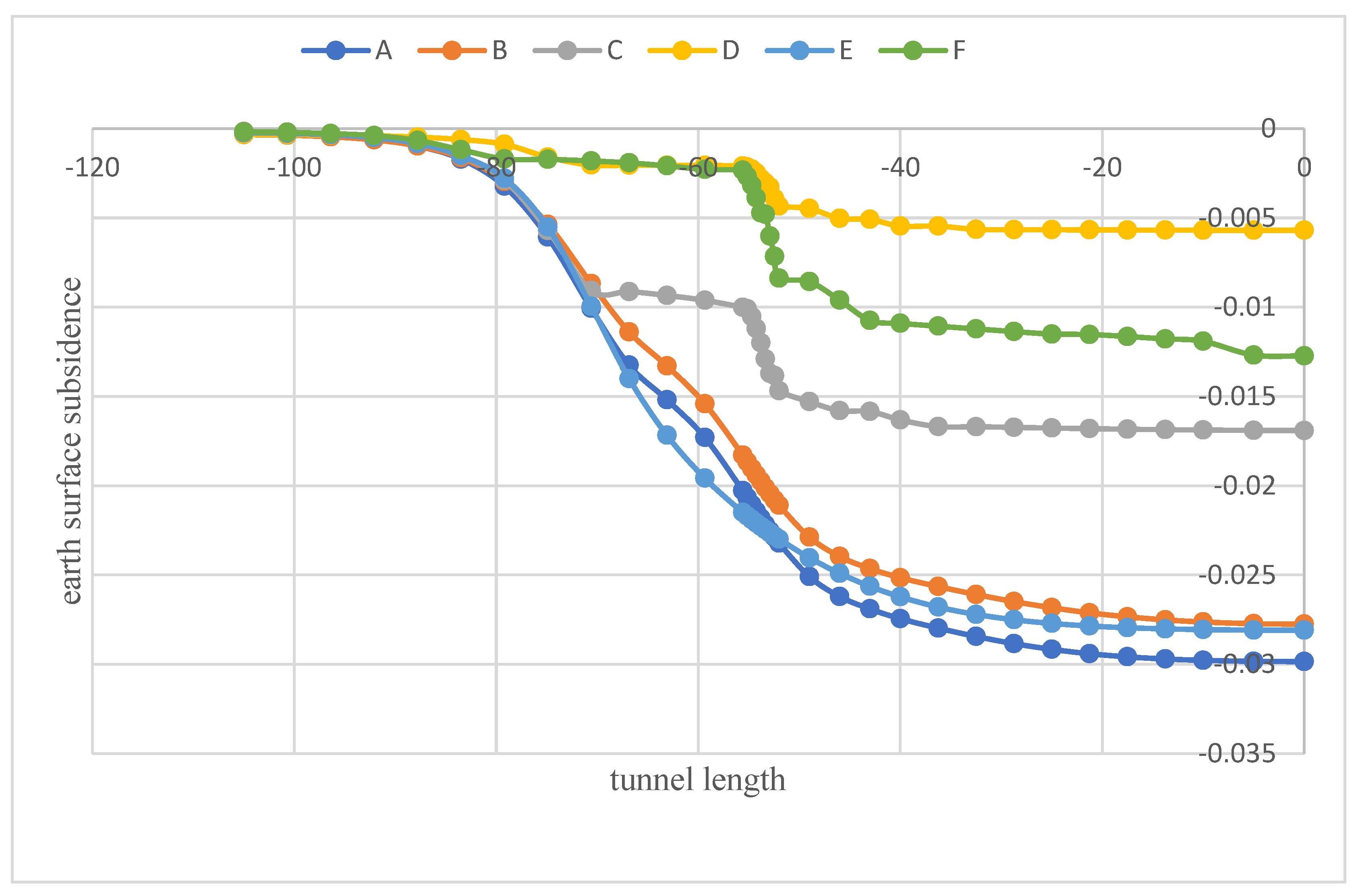
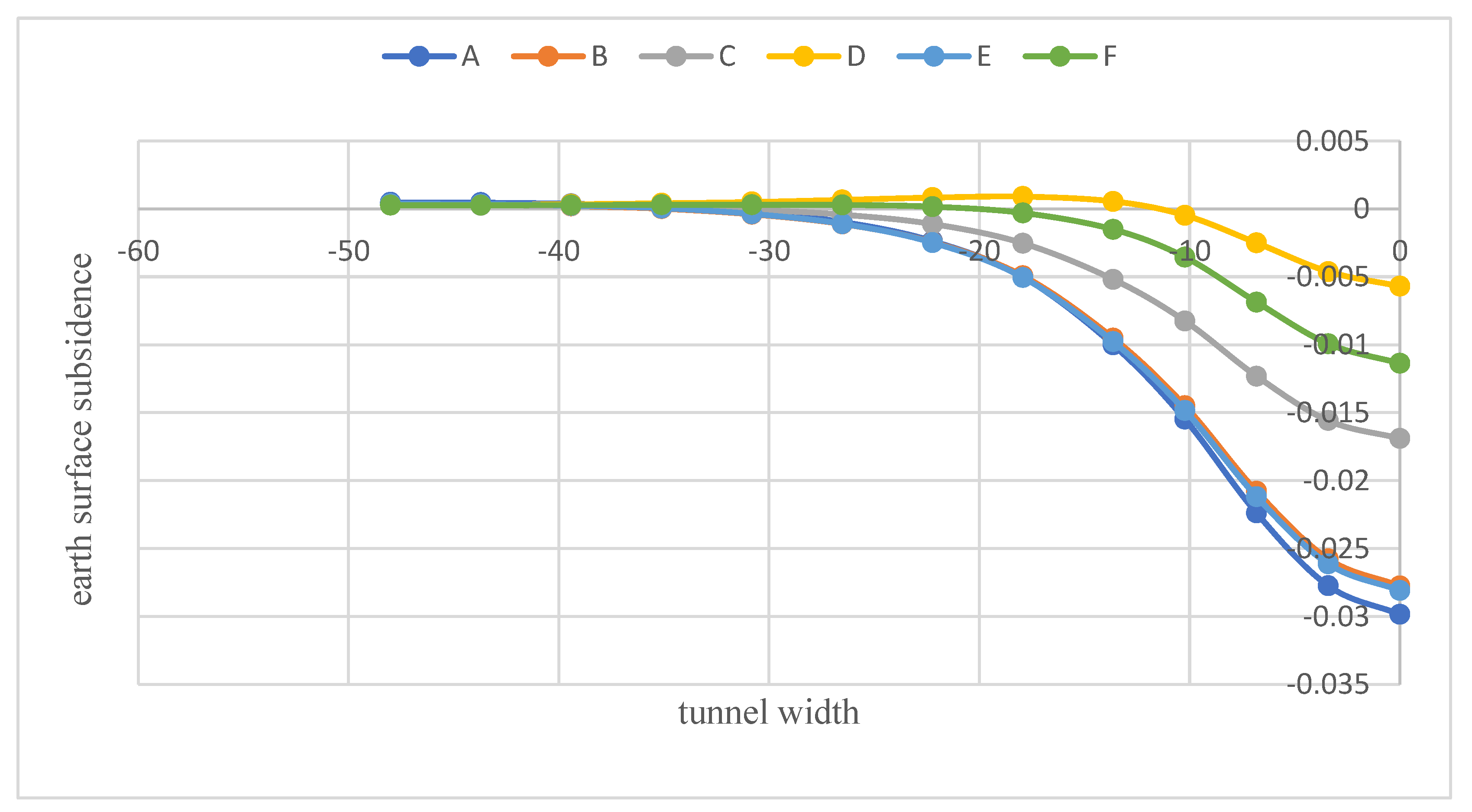
4.1. Comparison of Surface Subsidence between All Patterns
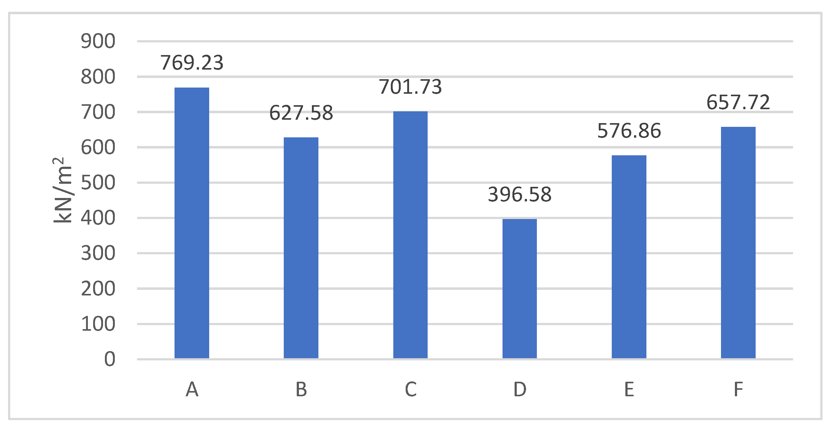
4.2. Comparison of Effective Mean Stresses of All Patterns
5. Conclusions
Author Contributions
Institutional Review Board Statement
Informed Consent Statement
Data Availability Statement
Conflicts of Interest
References
- Wang, Z.; Sheng, J.; Wang, R.; Li, X.; Xiao, Y.; Yi, Z. Analysis of Microtremor Exploration Application and Construction Monitoring in a Large-Diameter Shield Tunnel. Appl. Sci. 2023, 13, 263. [CrossRef]
- Wu, X.; Li, Y.; Gong, M.; Wu, H.; Wu, Y. Deformation and Stress Law of Surrounding Rock for a Bifurcated Tunnel with a Super-Large Section: A Case Study. Appl. Sci. 2023, 13, 12852. [CrossRef]
- Zhou, Z.; Zhou, X.; Li, L.; Liu, X.; Wang, L.; Wang, Z. The Construction Methods and Control Mechanisms for Subway Station Undercrossing an Existing Tunnel at Zero Distance. Appl. Sci. 2023, 13, 8826. [CrossRef]
- Sahu Smruti Ranjan; Rawat Kishan Singh. Analysis of Land subsidence in coastal and urban areas by using various techniques. Indonesian Journal of Geography 2023, Volume 55, Issue 3, Pages 488 – 495. [CrossRef]
- Ebru Ağbay; Tamer Topal. Evaluation of twin tunnel-induced surface ground deformation by empirical and numerical analyses (NATM part of Eurasia tunnel, Turkey). Computers and Geotechnics 2020, 119 103367. [CrossRef]
- Kuanda Fang; Zhiyong Yang; Yusheng Jiang; Zhengyang Sun; Zhenyong Wang. Surface subsidence characteristics of fully overlapping tunnels constructed using tunnel boring machine in a clay stratum. Computers and Geotechnics 2020, 125 103679. [CrossRef]
- Techn; L.v. Rabcewicz. The New Austrian Tunneling Method. Waterpower 1964, 16. 11. pp. 453-457.
- Shi J.W.; Fu Z.Z.; Guo W.L. Investigation of geomatic effects on three-dimensional tunnel deformation mechanisms due to basement excavation. Computers and Geotechnics 2019, 106, 108-116. [CrossRef]
- Mukhtiar Ali Soomro; Manoj Kumar; Hao Xiong; Dildar Ali Mangnejo; Naeem Mangi. Investigation of effects of different construction sequences on settlement and load transfer mechanism of single pile due to twin stacked tunnelling. Tunnelling and Underground Space Technology 2020, 96 103171. [CrossRef]
- G.S. Zeng; H.N. Wang; L.S. Luo; M.J. Jiang. Analytical solution of displacement and stress induced by the sequential excavation of noncircular tunnels in viscoelastic rock. International Journal of Rock Mechanics and Mining Sciences 2020, 134 104429. [CrossRef]
- Liu J; Ma B; Cheng Y. Design of the Gongbei tunnel using a very large cross-section pipe-roof and soil freezing method. Tunneling and Underground Space Technology 2018, 72:28–40. [CrossRef]
- Yang X; Li Y. Research of surface settlement for a single arch long-span subway station using the Pipe-roof Pre-construction Method. Tunneling and Underground Space Technology 2018, 72:210–217. [CrossRef]
- Niedbalski Z; Małkowski P; Majcherczyk T. Application of the NATM method in the road tunnelling works in difficult geological conditions-The Carpathian flysch. Tunneling and Underground Space Technology 2018, 74:41–59. [CrossRef]
- W. Wittke; B. Pierau; C. Erichsen. New Austrian Tunnelling Method (NATM) Stability Analyses and 12. Design. WBI GmbH, Henricistr. Aachen Germany 2002, 50. 52072.
- Gokceoglu, C.; Aygar, E.B.; Nefeslioglu, H.A.; Karahan, S.; Gullu, S. A Geotechnical Perspective on a Complex Geological Environment in a High-Speed Railway Tunnel Excavation (A Case Study from Türkiye). Infrastructures 2022, 7, 155. [CrossRef]
- Aygar, E.B. Performance of the Flexible and Rigid Lining under Earthquake Impact and Weakness of the New Austrian Tunneling Method (NATM) Principles, a Specific Case Study of the Bolu Tunnel. Sustainability 2023, 15, 15544. [CrossRef]
- M M. Farias; A H M. Junior; A P. Assis. Displacement control in tunnels excavated by the NATM: 3-D numerical simulations. Tunneling and Underground Space Technology 2004, 19. 283–293. [CrossRef]
- Boldini, Daniela; Lackner, Roman; Mang, Herbert. A. Ground-shotcrete interaction of NATM tunnels with high overburden. Journal of Geotechnical and Geoenvironmental Engineering 2005, 131 (7), 886 - 897. [CrossRef]
- R. Schwingenschloegl; C. Lehmann. Swelling rock behaviour in a tunnel: NATM-support vs. Q-support – A comparison. Tunneling and Underground Space Technology 2009, 24. 356–362. [CrossRef]
- T. Svoboda; D. Masin; J. Bohac. Class A predictions of a NATM tunnel in stiff clay. Computers and Geotechnics 2010, 37. 817-825. [CrossRef]
- H. Hosseini. Geotechnical study report on Tehran third south subway line by Soil and foundation engineering. Tehran consulting engineers 2008, Jahadtosee.co.
- Liu. Xiao; Yan. Peng; Chen. Ming; Luo. Sheng; Lu. Ang; Lu. Wenbo; Huang. Shuling; Wang. Gaohui. Optimization analysis of excavation procedure design of underground powerhouses under high in situ stress in China. Applied Sciences 2021, 11 (21), 10252. [CrossRef]
- . www.balkema.nl; www.szp.swets.nl PLAXIS B.V. P.O. Box 572, 2600 AN DELFT, Netherlands. A.A. Balkema publishers. ISBN 9026518196.
- CVR consultant engineers. Design consultant of Tehran third south subway line. 2010, 210.
- CVR consultant engineers. Monitoring and instrumenting of tunnel behavior. Design consultant of Tehran third south subway line. 2011, TUSRC/RTI/L3/CVR/C/REP/TUN/P3/H/021/REV.0.
| Upper layer (sand) |
Middle layer (clay with silt) |
Bottom layer (clay with silt) |
|
|---|---|---|---|
| E (kN/m2) | 1.75*104 | 3.75*104 | 5.5*104 |
| ȣunsat(kN/m3) | 16.9 | 16.9 | 16.9 |
| ȣsat (kN/m3) | 20.250 | 20.250 | 20.250 |
| ψ(º) | 0 | 0 | 0 |
| φ(º) | 27 | 27 | 27 |
| ѵ | 0.35 | 0.35 | 0.35 |
| C (kN/m2) | 40 | 40 | 40 |
| K0 | 0.548 | 0.492 | 0.504 |
| E (kN/m2) |
ȣunsat (kN/m3) | ѵ | EA(kN/m) | EI (kNm2) |
d (m) | W (kN) | |
|---|---|---|---|---|---|---|---|
| Shotcrete | - | - | 0.2 | 6.103*106 | 2.215*104 | 0.209 | 7.2 |
| Final concrete | 2.387*107 | 25 | 0.2 | - | - | - | - |
| Parameter | Definition |
|---|---|
| E | Elasticity module |
| ȣunsat | Unsaturated unit weight |
| ȣsat | Saturated unit weight |
| Ψ | Angel of dilation |
| Φ | Internal friction angel |
| Ѵ | Poison’s ratio |
| C | Cohesion |
| K0 | Coefficient of lateral earth pressure |
| EA | Normal stiffness (Axial rigidity) |
| EI | Flexural rigidity |
| d | Equivalent thickness |
| W | Unit weight |
Disclaimer/Publisher’s Note: The statements, opinions and data contained in all publications are solely those of the individual author(s) and contributor(s) and not of MDPI and/or the editor(s). MDPI and/or the editor(s) disclaim responsibility for any injury to people or property resulting from any ideas, methods, instructions or products referred to in the content. |
© 2024 by the authors. Licensee MDPI, Basel, Switzerland. This article is an open access article distributed under the terms and conditions of the Creative Commons Attribution (CC BY) license (http://creativecommons.org/licenses/by/4.0/).


