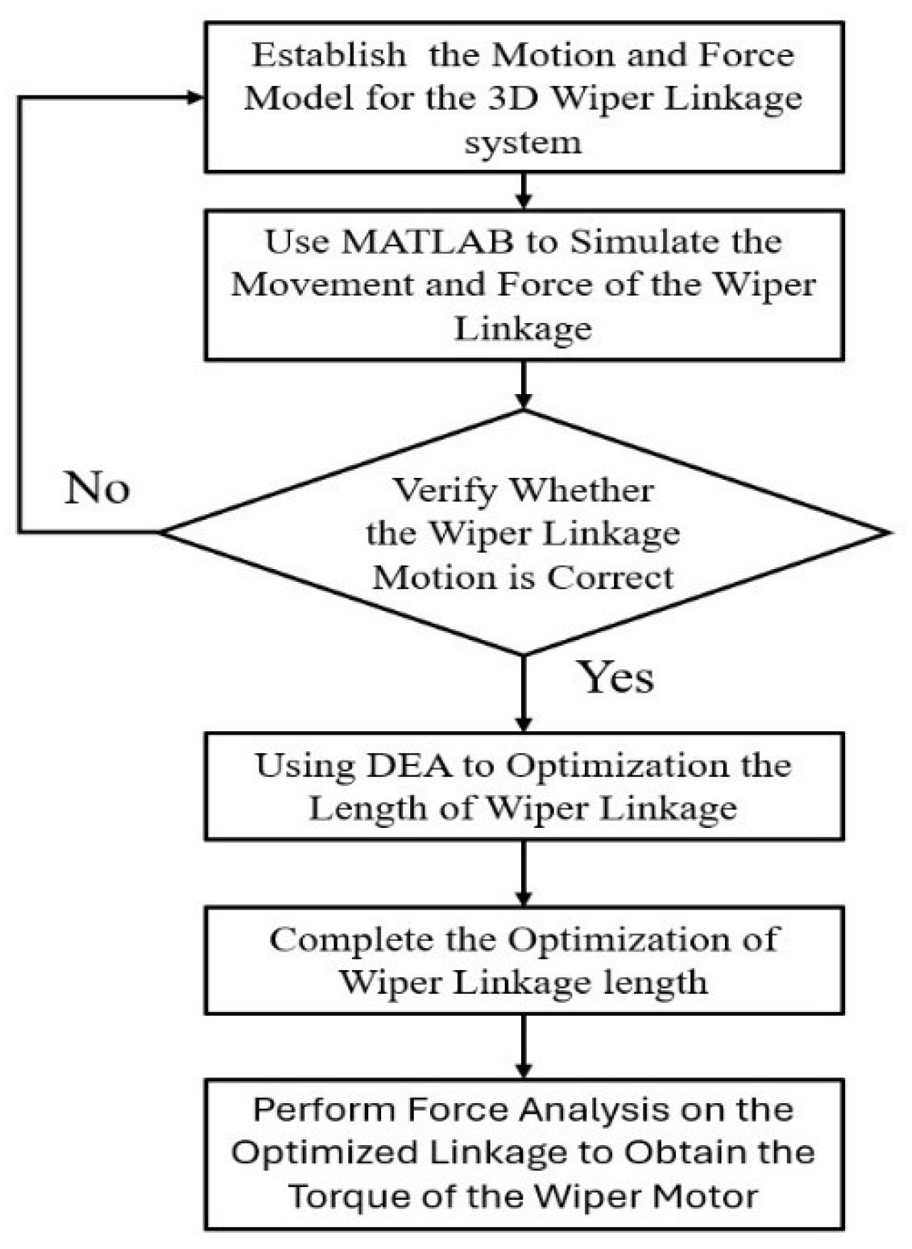
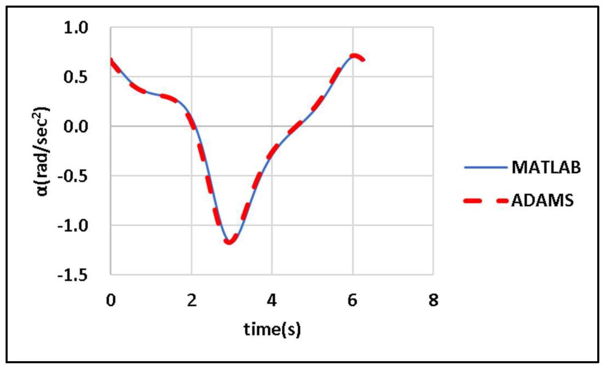
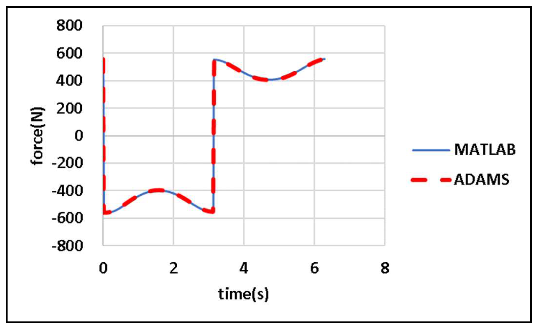
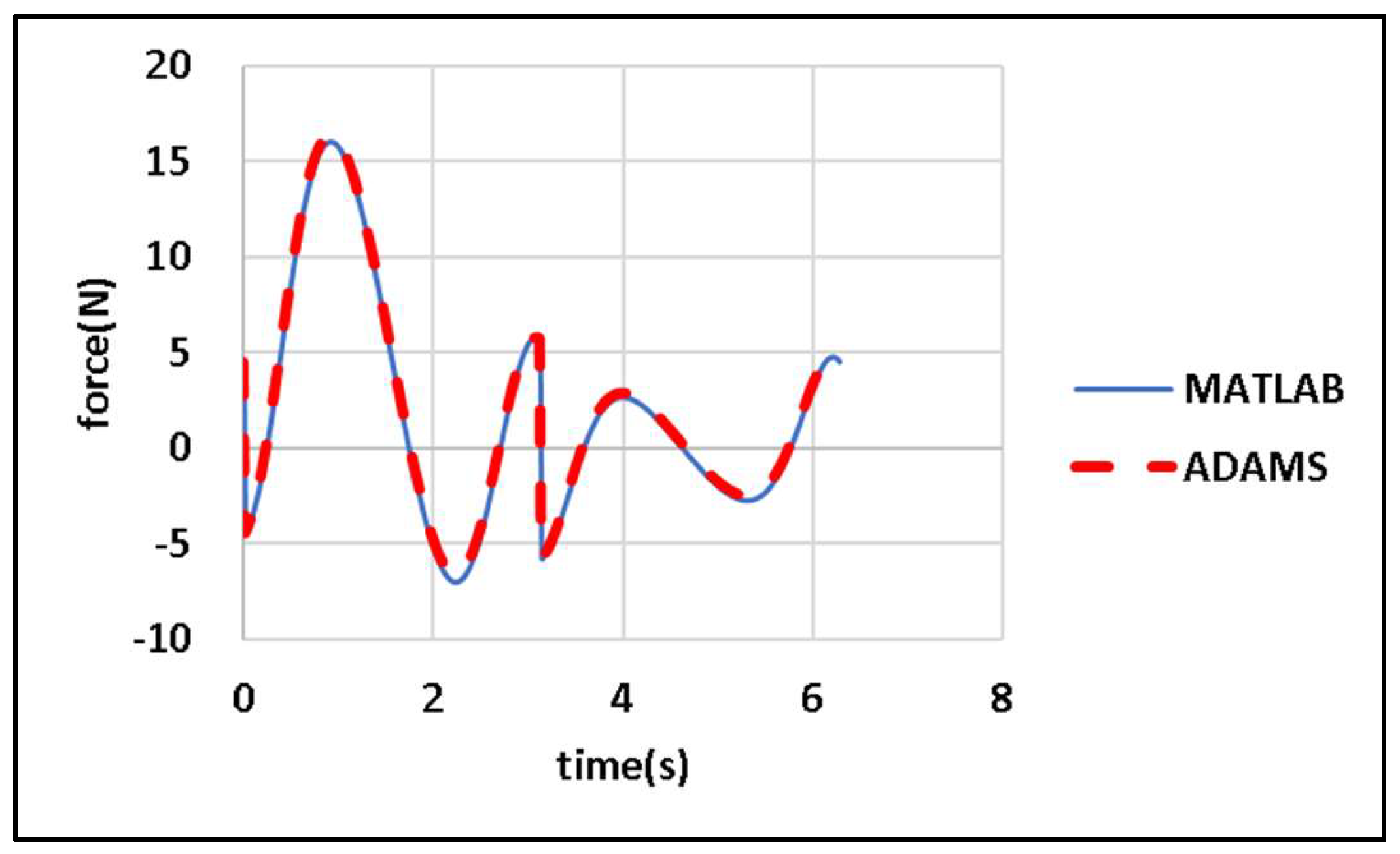
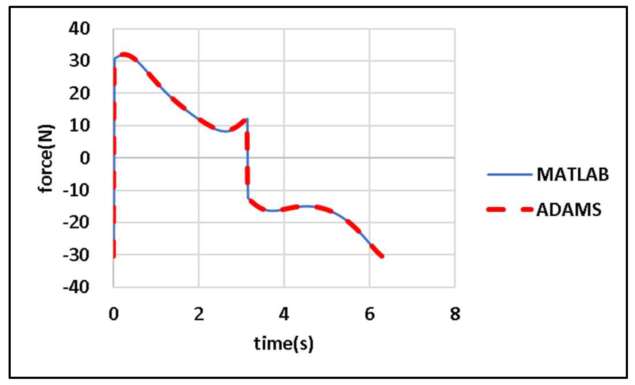
Mathematical formulas for
and for
are provided in
Section 2.1.
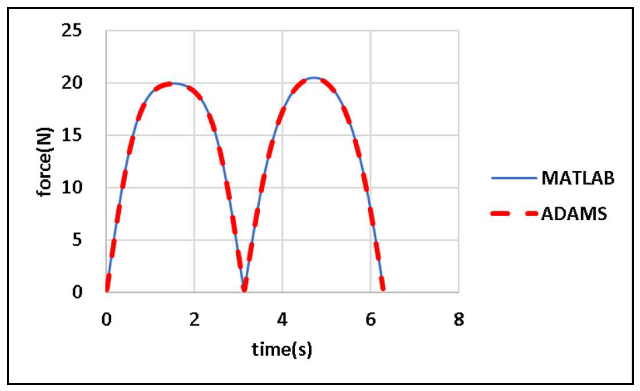
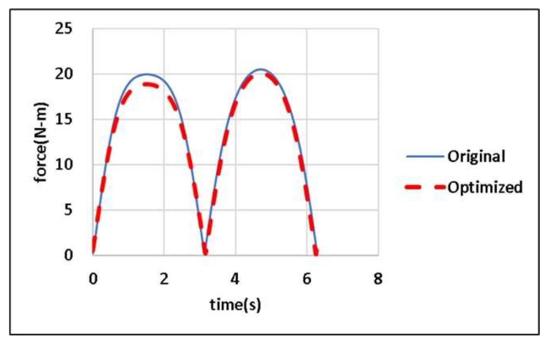
Section 2.2 presents the mathematical formulas for the magnitudes of the joint forces acting on each link and the driving torque of the motor. Finally,
Section 2.3 describes the use of DE to minimize the objective function of the present study under the 10 considered constraints. Finally, this section discusses a dynamic model of the CDLS. This model and Euler’s laws of motion can be used to determine the magnitudes of the joint forces acting on each link and the driving torque of the motor. The torque exerted by an external load on the output links is considered in the analysis to ensure that the crank rotates at a constant speed.
2.1. Wiper Linkage Motion Model
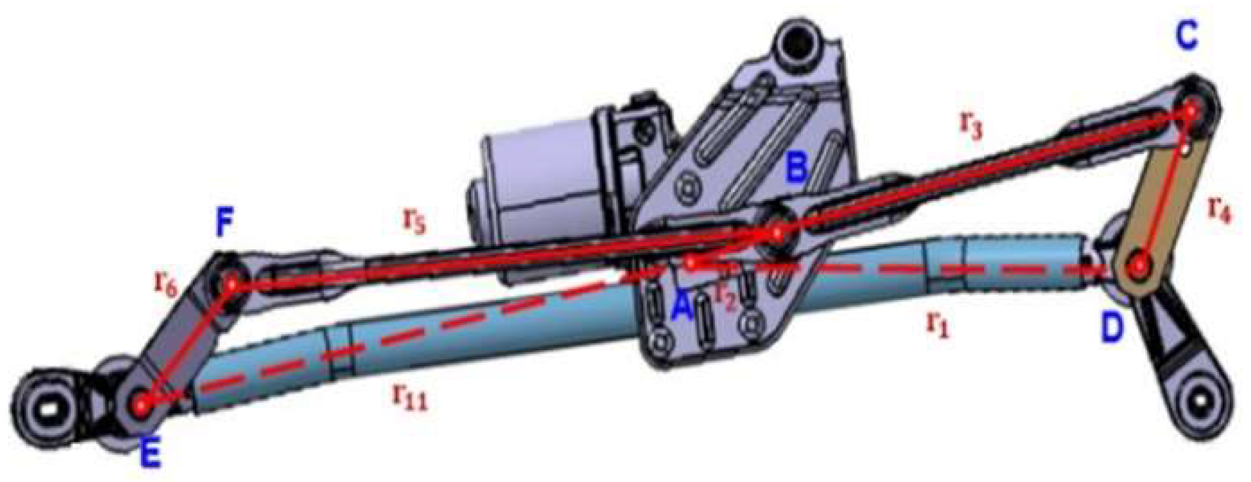
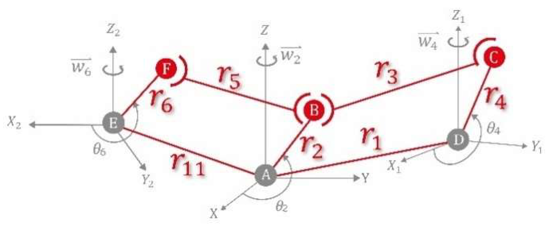
Figure 2 displays the structure of a CDLS. The vectors of the crankshaft’s axis are not mutually parallel with the vectors of the output links of the wipers on both sides; therefore, the linkages cannot be simplified into a planar model. To precisely optimize the rod lengths and meet the requirements of practical applications, we established a simplified three-dimensional kinematic model of a CDLS (
Figure 4). For this model, three Cartesian coordinate systems were established:
,
, and
. Point A is the origin of coordinate system
, and the motor shaft vector is aligned along the
-axis. Link AB rotates in the
plane around the
-axis. Point D is the origin of coordinate system
, and Link CD rotates about the
-axis within the
plane. Finally, point E is the origin of coordinate system
, and Link EF rotates about the
-axis within the
plane.
Figure 2.
Structure of a CDLS.
Figure 2.
Structure of a CDLS.
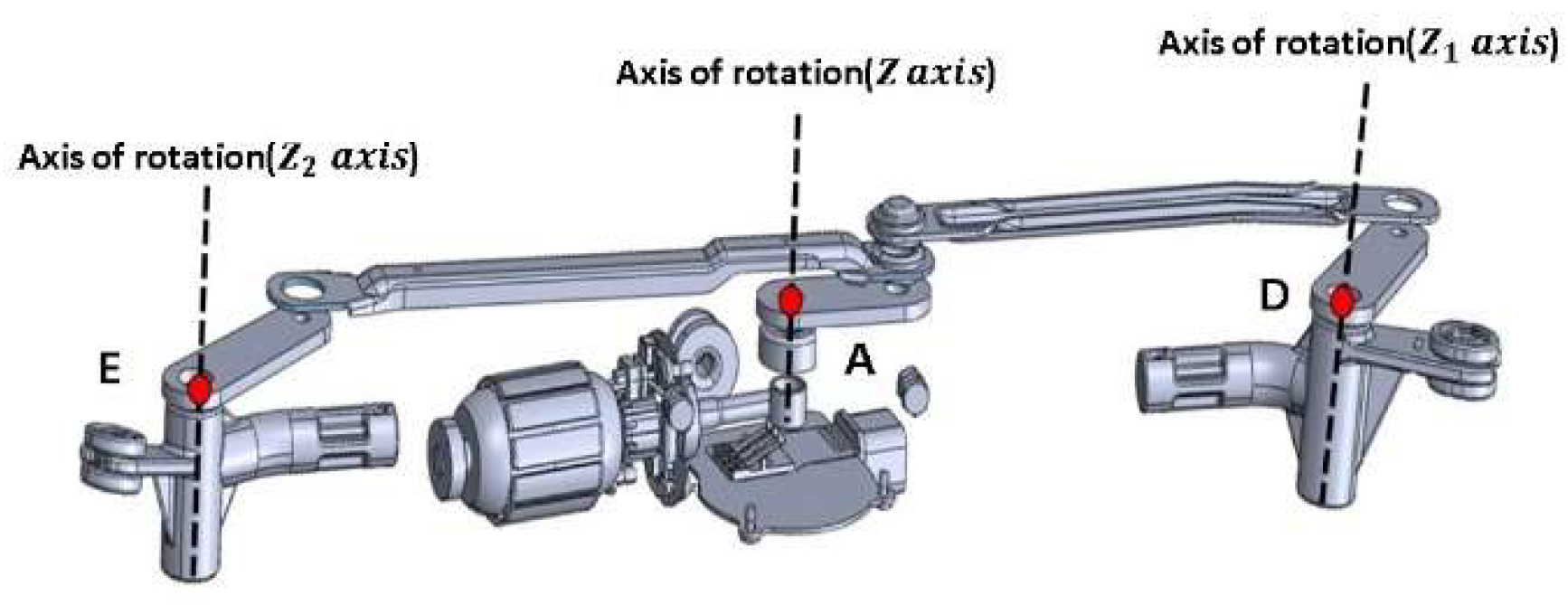
Figure 3.
Rotating shafts, coordinate origins, and axes of rotation.
Figure 3.
Rotating shafts, coordinate origins, and axes of rotation.
Figure 4.
Simplified three-dimensional kinematic model of a CDLS.
Figure 4.
Simplified three-dimensional kinematic model of a CDLS.
The link components of the CDLS were measured in millimeters, and angles were measured in radians .
The linkage system, which includes Links AB, BC, CD, and AD, drives the wiper on the driver side of the CDLS. Link AD is fixed, and Link AB, commonly referred to as the crankshaft, is the input link that receives power to drive Links BC and CD. Link BC is a connecting link, and Link CD is the output link on the driver side of the CDLS. Link AB is the shortest link and can rotate 360°. The lengths of these four driver-side links must satisfy Grashof's law [
14]. ABCD is a spatial four-bar linkage mechanism; points A, B, C, and D have a rotational joint R, spherical joint S, spherical joint S, and rotational joint R, respectively. This mechanism is commonly known as an RSSR mechanism. The angle
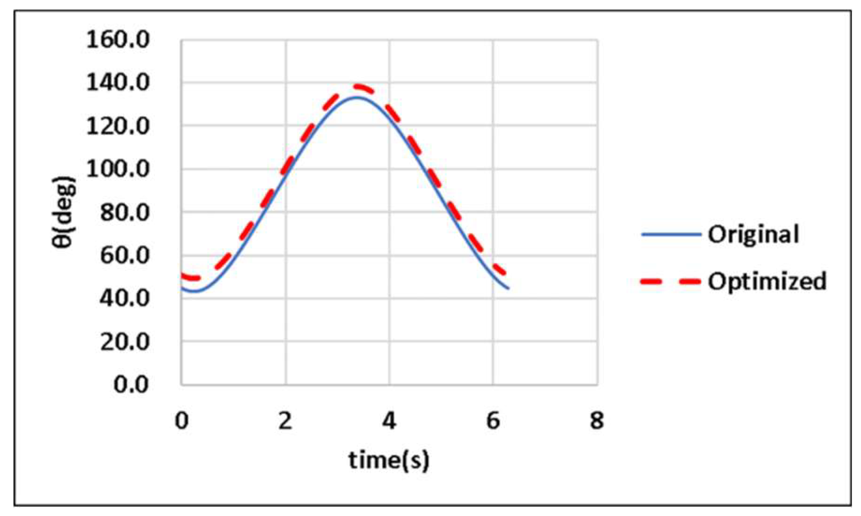
between Links BC and CD is commonly referred to as the transmission angle on the driver side of the CDLS [
31], and
varies as the input link (Link AB) rotates. The mechanism achieves optimal efficiency (maximized effective torque) when the transmission angle is π/2 radians. Typically, the transmission angle must be able to vary from 40° to 140° [
31].
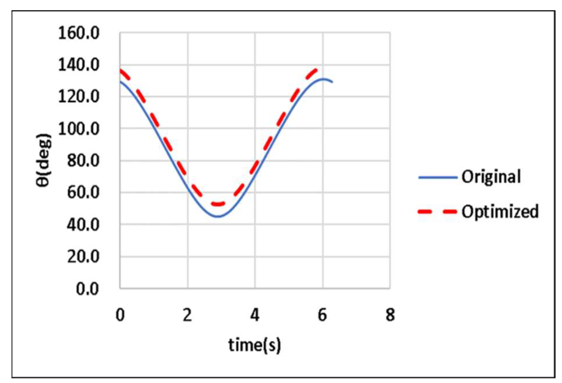
The linkage responsible for driving the wiper on the passenger side of the CDLS comprises Links AB, BF, AE, and EF. Link AE is a fixed link, and Link AB is the input link (crankshaft) that powers Links BF and EF. Link BF and Link EF are the connecting and output links, respectively, on the passenger side of the CDLS, and the angle between Links BF and FE is the transmission angle on the passenger side of the CDLS. For the driver side, the efficiency is optimized when the transmission angle is π/2 radians.
The lengths of Links AB, BC, CD, and AD are denoted as
,
,
and
, respectively. In addition, the angles between Link AB and the
X-axis, Link DC and the
X1-axis, and Link EF and the
X2-axis are denoted as
,
, and
, respectively (refer to
Figure 4). Similarly, the lengths of Links BF, FE, and AE are denoted as
, and
respectively. The lengths of Links AB, BC, CD, and AD (passenger-side links) must also satisfy Grashof's law. ABFE is also a spatial four- bar linkage mechanism with a rotational joint R, spherical joint S, spherical joint S, and rotational joint R at points A, B, F, and E, respectively (
Figure 4).
The following paragraphs discuss the mathematical formulas for the established model.
2.1.1. Matrices for Three-Dimensional Rotations
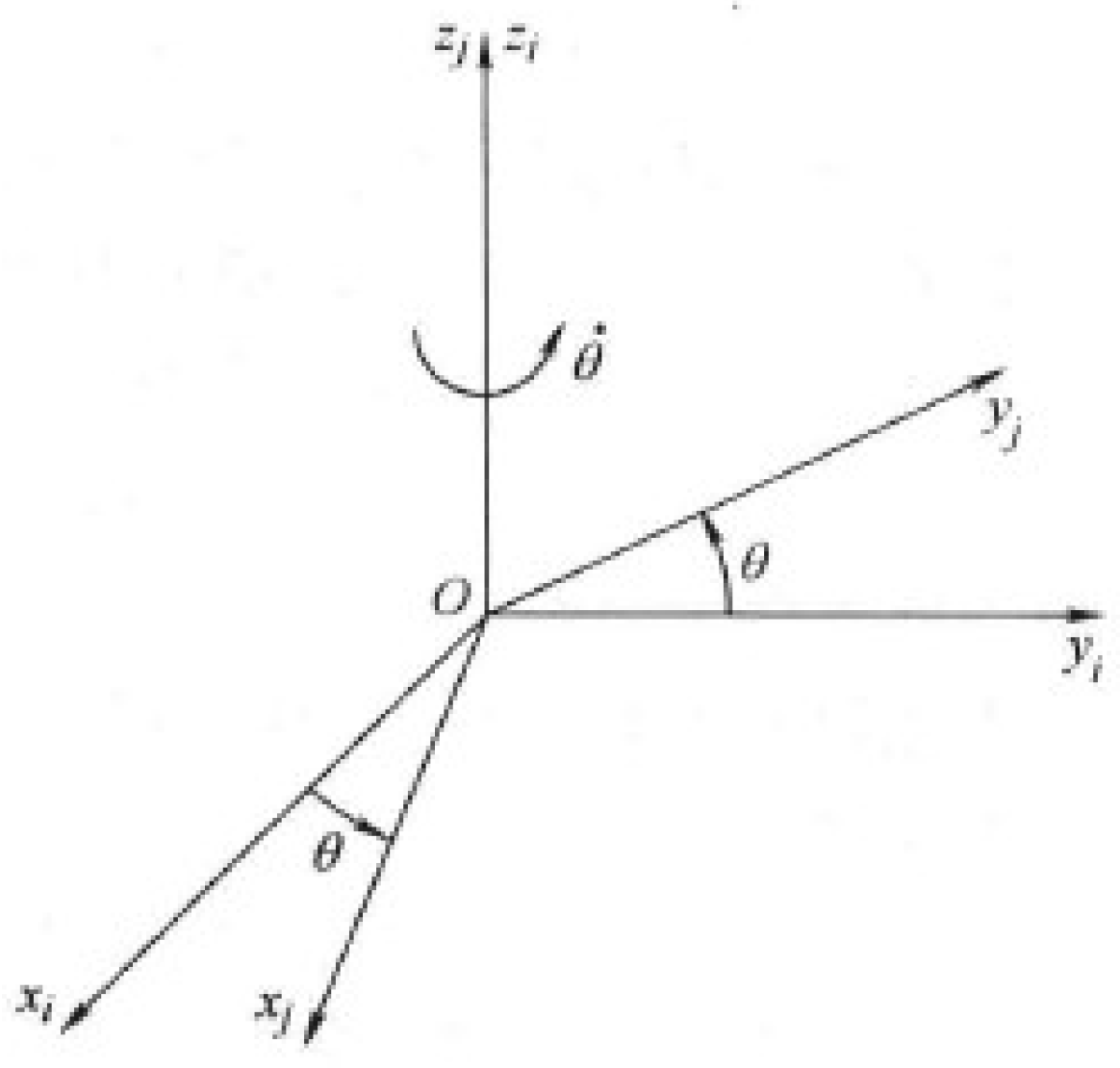
The
-axis is defined as running horizontally left and right on the paper, and the
-axis is defined as running vertically up and down on the paper. The diagonal line represents the
-axis, which is perpendicular to the other two axes; its positive direction is out of the paper, and its negative direction is into the paper. The positive axes of the standard
coordinate frame point in the out, right, and up directions (
Figure 5). The standard definitions of the rotations about the three principle axes are first explained. Consider two right-handed rectangular coordinate systems with a common origin, as depicted in
Figure 5. The coordinate system
can be obtained from the coordinate system
by performing a counterclockwise rotation about the
-axis by an angle
. The sign of
follows the right-hand rule: When the thumb points in the positive direction of the
-axis, a counterclockwise rotation from the
-axis to the
-axis indicates a positive
value, whereas a clockwise rotation indicates a negative
value. The coordinate transfer matrix is expressed as follows:
where (
) in the upper right corner of the square matrix indicates that the coordinate system
is obtained by rotating the coordinate system
about the
-axis by the angle
. Two vectors in the
and the
systems, namely (
) and (
), respectively, have the following relationship:
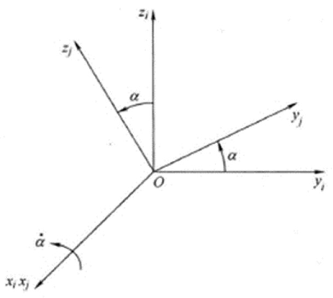
As shown in
Figure 6, the coordinate system
can be obtained from the coordinate system
by performing a counterclockwise rotation about the
-axis by an angle
. The relevant coordinate transfer matrix is expressed as follows:
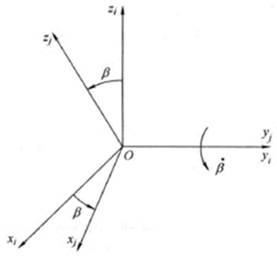
Similarly, coordinate system
is obtained from coordinate system
by performing a counterclockwise rotation about the
-axis by an angle
(
Figure 7). The relevant coordinate transfer matrix is expressed as follows:
2.1.2. Multiple Rotations
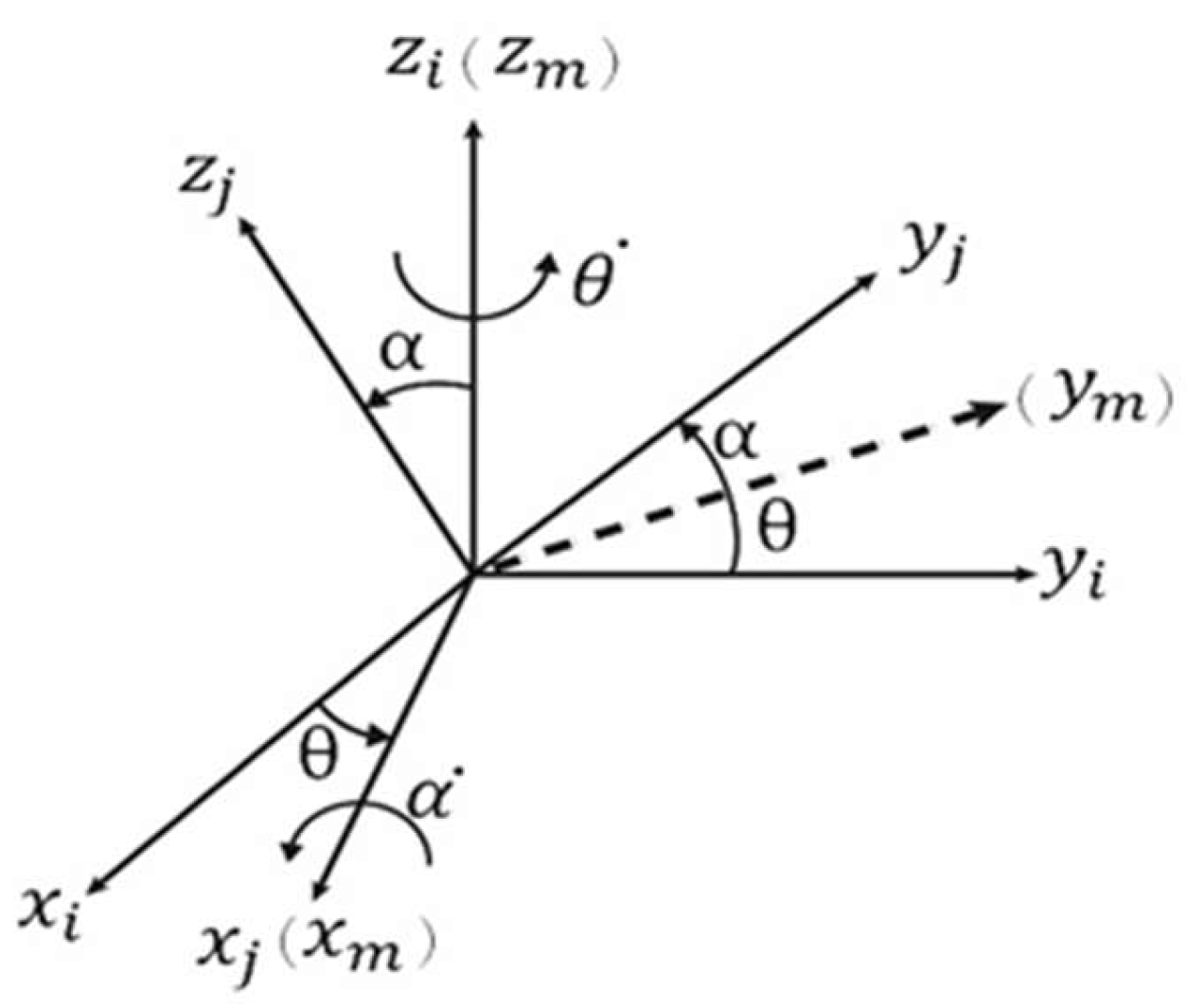
As displayed in
Figure 8, the orientation of the
coordinate system relative to the
coordinate system can be regarded as a transformation involving two steps. First, the
coordinate system is rotated around the
-axis by
θ, resulting in the
coordinate system. The matrix relationship for this transformation is given as follows:
where
is a vector in the
coordinate system. This vector can be expressed in the
coordinate system as
by using Equation (2).
Second, the
coordinate system is rotated around the
-axis by an angle
to become the
coordinate system; the corresponding coordinate transformation matrix relationship can be expressed as follows:
where
is a vector in the
coordinate system. This vector can be expressed in the
system as follows:
Equation (4) can be used to achieve continuous transformations between coordinate systems.
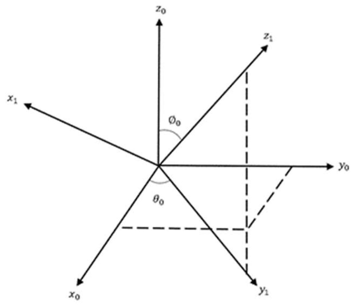
If an axis of a reference frame is specified, its coordinate system can be conveniently selected, as shown in
Figure 9. If
is the specified axis of the system
, the polar and azimuthal angles are
and
, respectively. First, the coordinate system
is rotated around the
-axis clockwise by an angle
, resulting in the
coordinate system. Next, the
coordinate system is rotated around the
-axis clockwise by an angle
, transforming it into the
coordinate system. Here
is a vector in the
coordinate system. This vector can be expressed in the
coordinate system as follows:
2.1.3. Motion of the Driver-Side Linkage of the CDLS
The
-axis of the
coordinate system is aligned with the crankshaft axis, and the crank itself is positioned in the
plane of this coordinate system. Assume that the unit vector of the main output shaft's axis
is (
). A reference coordinate system
is defined for the main output shaft. Here,
is a vector in the
coordinate system. This vector can be expressed in the
coordinate system as follows by using Equation (5):
Assume that vectors
and
are defined as follows in the
coordinate system:
Vector
can then be expressed in the
coordinate system as follows:
Similarly, assume that vectors
and
are defined as follows in the
coordinate system:
The following equality can be derived by considering
Figure 3 and using the vector loop method:
Expressing this vector equality in terms of the
coordinate system results in the following relations:
The solution of Equation (12) is given as follows:
Squaring Equations (10) and (11) and adding them results in the following relation without
:
where
and
.
The half-angle formula for tangent can be used to express Equation (14) in the following form:
The following expression is obtained by solving Equation (15) for
:
Thus, the following equation is obtained:
In Equation (16),
has two solutions representing the motion of the linkage above or below the
-axis. The following solution is obtained for
when the positive square root is considered:
The following expression is obtained by substituting Equation (17) into Equations (10) and (11):
The angular velocity
(the derivative of
with respect to time) of Link AB is fixed at 1 rad/s. The time derivatives of
(
'),
(
), and
(
), which is the angular velocity of Link DC) for Link DC are obtained by differentiating Equations (10)–(12) with respect to time (
t).
The angular velocity of Link AB is fixed at 1 rad/s; therefore, the angular acceleration
of this link is 0. Equations (10)–(12) are differentiated twice with respect to time (
t) to obtain
from
from
, and
from
for Link DC;
is the angular acceleration of Link DC.
and
The transmission angle
for the driver side of the CDLS can be expressed as follows by using the dot product of vectors CD and CB:
2.1.4. Motion of the Passenger-Side Linkage of the CDLS
Assume that the unit vector of the main output shaft's axis
is (
). An
coordinate system is established on the auxiliary output shaft, where the
- axis is aligned with the auxiliary output shaft’s axis of rotation. The matrix relationship between the
and
coordinate systems is as follows:
Assume that vectors
and
are defined as follows in the
coordinate system:
The vector
can be expressed in
as
Similarly, assume that vectors
and
are defined as follows in the
coordinate system:
Similar mathematical formulas are valid for the motion of the passenger-side linkage of the CDLS. In this case,
is the input variable of the input link AB, and
is the unknown output of the output link EF. The following expressions are obtained by using the vector loop method and the half-angle formula for tangent:
with
and
.
The solution adopted for
is expressed as follows:
The time derivatives of
(
),
(
)
, and
(
), which is the angular velocity of Link EF) for Link EF are obtained as follows by using the method introduced in
Section 2.1.3:
and
Similarly, the time derivatives of
(
),
(
), and
(
), which is the angular acceleration of Link EF) for Link EF are expressed as follows:
The transmission angle
on the passenger side of the CDLS can then be expressed as follows:
2.2. Dynamic Analysis of the Linkage System
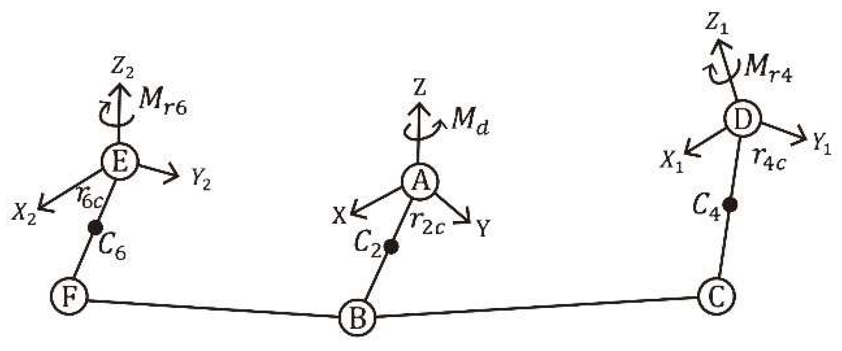
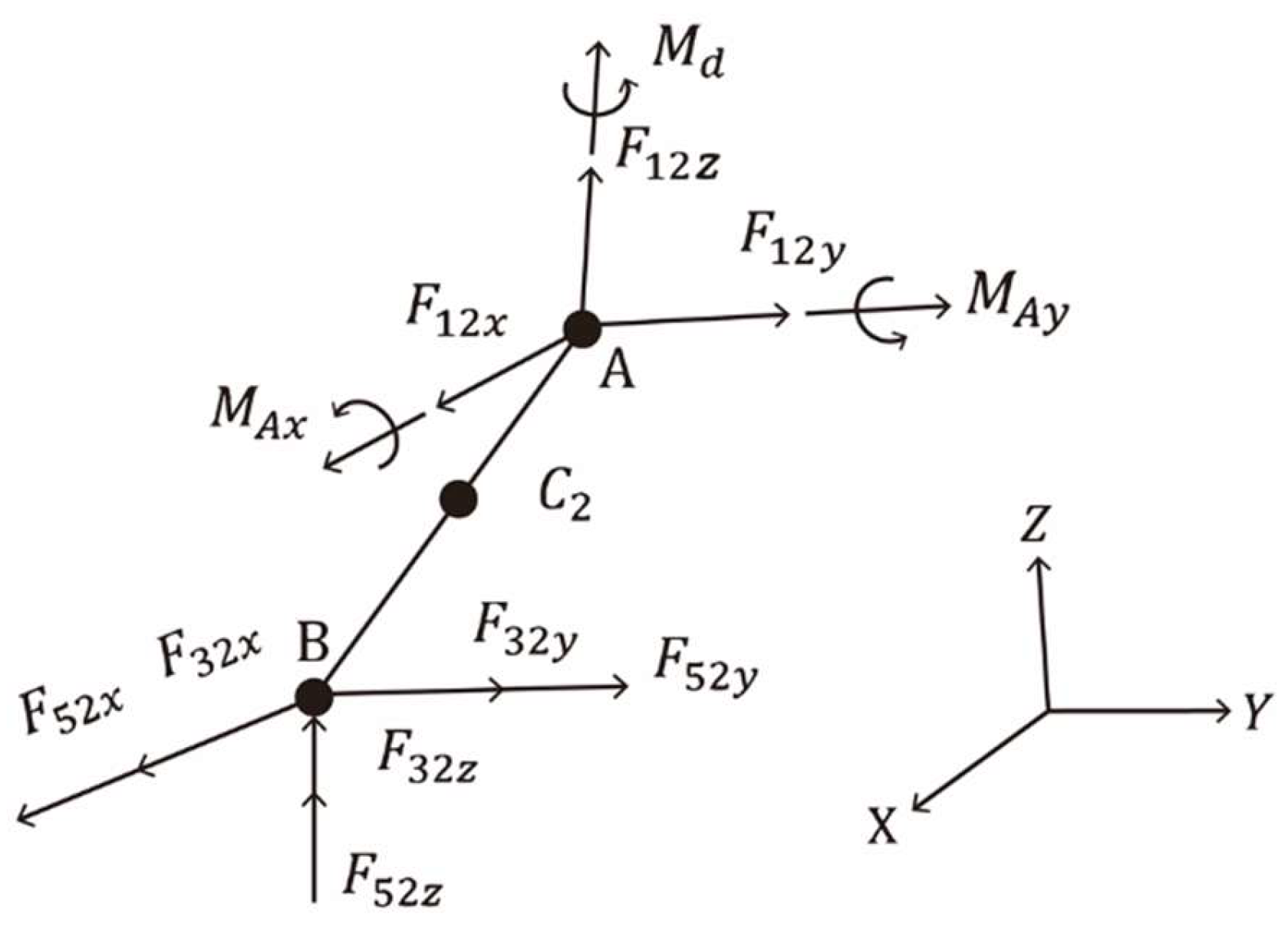
In
Figure 10,
represents the driving torque in the
direction at point A. The terms
and
represent external torques at point D in the
direction and at point E in the
direction respectively; both have known magnitudes. The driving torque required for Link AB to maintain a constant angular velocity is calculated. The joint forces, bearing forces, and driving torque in the CDLS are derived using Newton–Euler equations of motion. To simplify the dynamic analysis model, the following three assumptions are made:
Friction at the joints can be neglected.
All links are rigid bodies.
The effects of gravity are negligible.
All links in the mechanism are homogeneous.
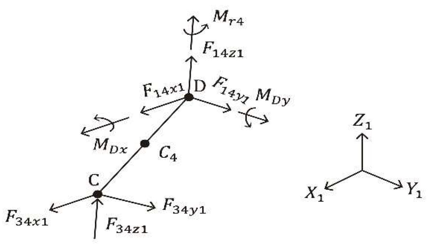
In
Figure 11,
, and
represent the reaction forces in the
,
, and
directions, respectively, at bearing D. The terms
,
, and
represent the components of the joint force exerted by Link BC on Link AB in the
,
, and
directions. The masses of Links AB, BC, and CD are denoted by
,
, and
, respectively, and
,
, and
are the acceleration components of the center of mass
of Link CD in each direction. The term
represents the mass moment of inertia of Link CD relative to its center of mass, and
and
are the reaction moments in the
and
directions, respectively, at bearing D. The position vector of the center of mass
of Link CD is denoted by
and expressed as follows:
where
is the acceleration of the center of mass
of Link CD in the
coordinate system.
Differentiating each component of vector
with respect to
t twice yields the following expressions:
Suppose that the force vector is scaled by a factor of in the direction of the unit vector of BC; that is,
The force balance equations and torque equations are as follows :
Using the Equation (41), (42), (43), (44 ), (45) and (46) we may obtain
,
,
and
as follow:
in which
and
.
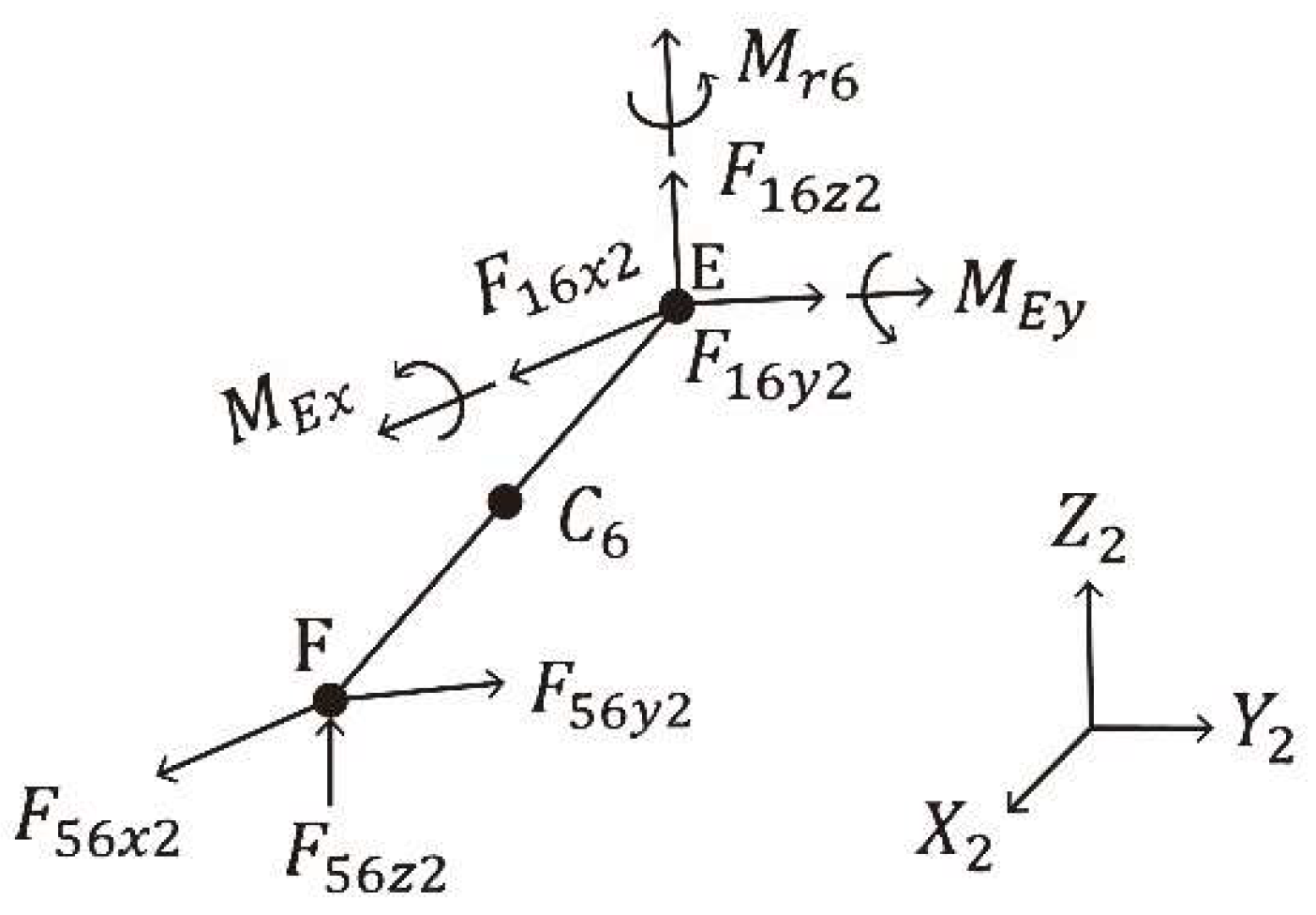
In
Figure 12,
,
, and
represent the reaction forces in the
,
, and
directions, respectively, at bearing E. Moreover,
,
, and
are the components of the joint force exerted by Link BF on Link EF in the
,
, and
directions, respectively. The terms
,
a6cy, and
a6cz represent the acceleration components of the center of mass
of Link EF in the
,
, and
directions, respectively. The term
I6 denotes the mass moment of inertia of Link EF relative to its center of mass;
and
are the reaction moments in the
and
directions, respectively, at bearing E; and
m5 and
m6 represent the masses of Links BF and EF, respectively.
The following matrix can be obtained in the
coordinate system by using the same method as that used for
Figure 11:
in which
In
Figure 13,
,
, and
represent the reaction forces in the
,
, and
directions, respectively, at bearing A. The acceleration components of the center of mass
of Link AB in the
,
, and
directions are
,
, and
, respectively. The term
represents the mass moment of inertia of Link AB relative to its center of mass. Moreover,
and
are the reaction moments in the
and
directions, respectively, at bearing A. The following matrix is obtained in the
coordinate system by using the same method as that used for
Figure 11:
in which
and
2.3. Optimization of the Angular Acceleration of the Output Links of the CDLS
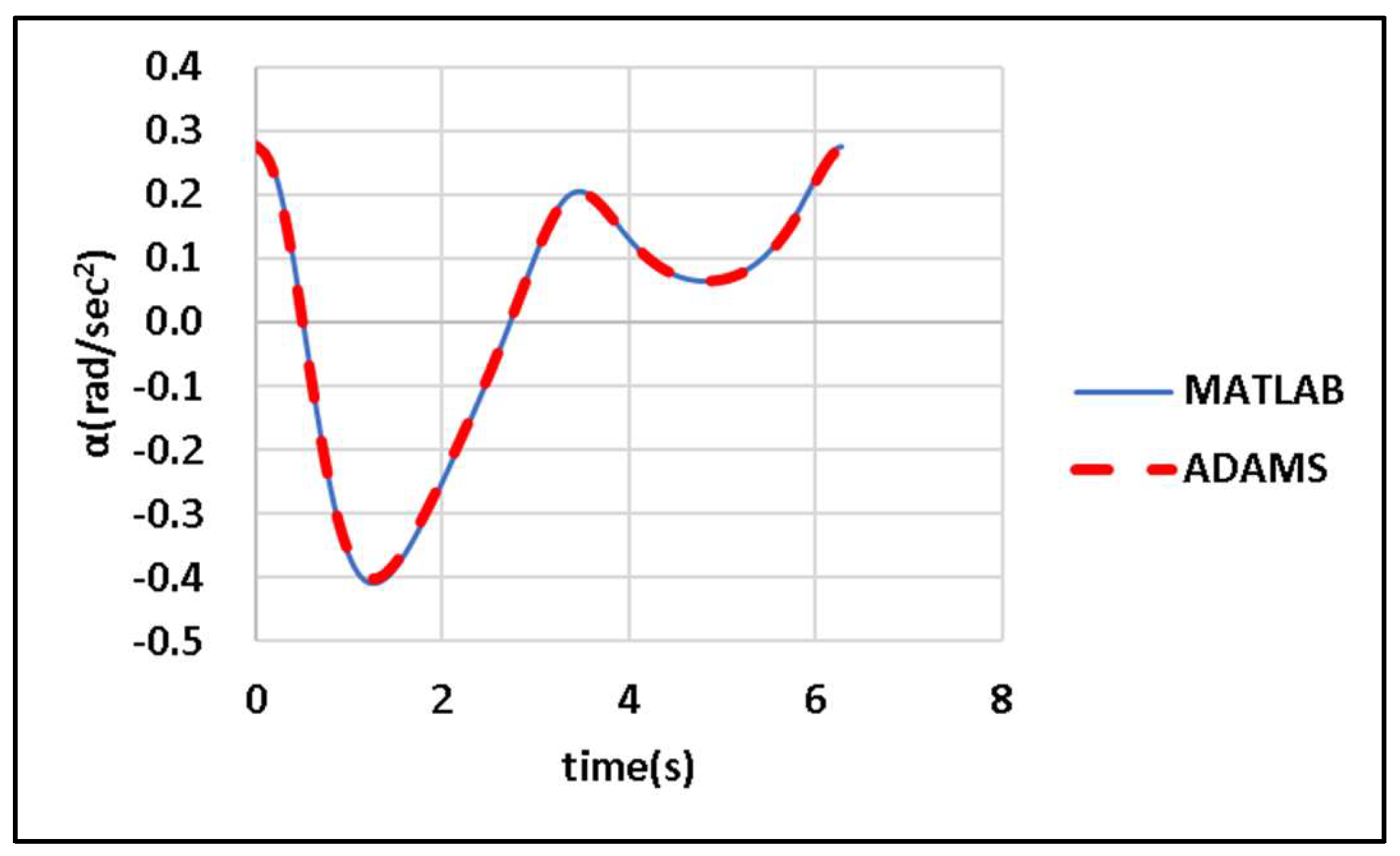
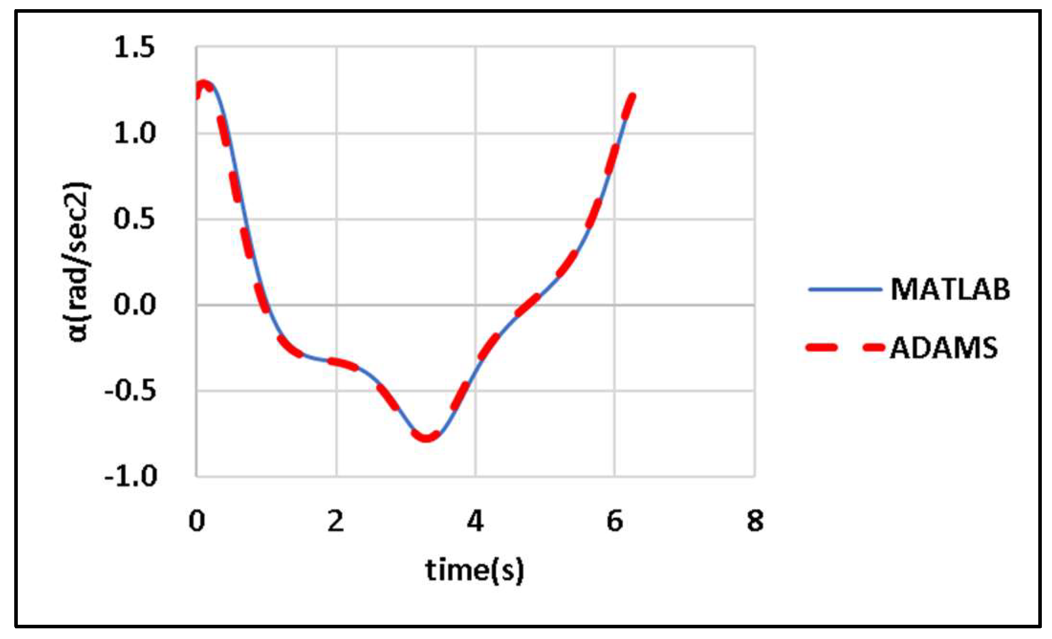
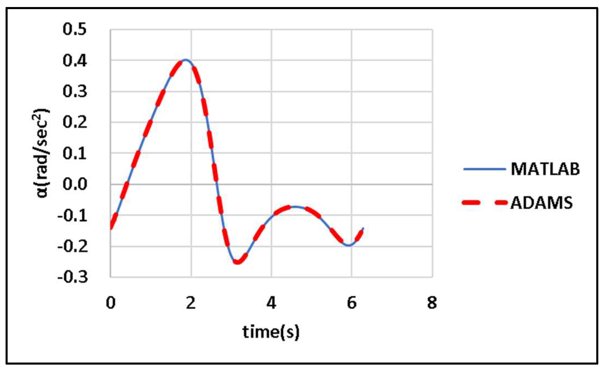
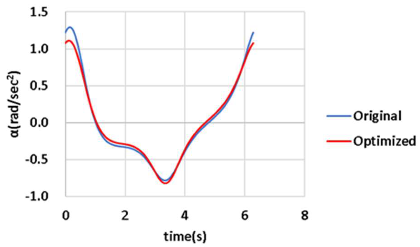
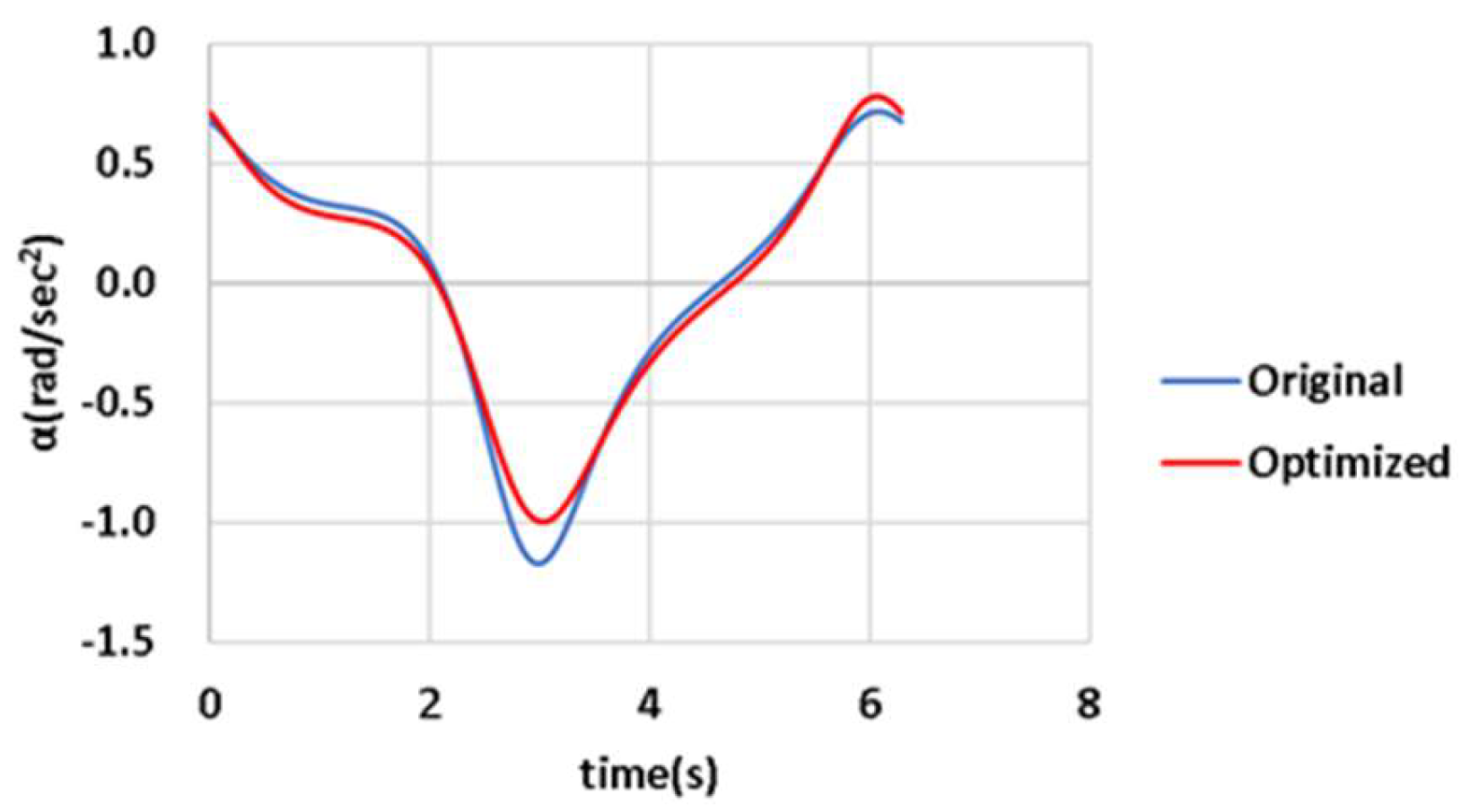
DE is applied to maximize the angular acceleration of the output links of the designed CDLS for windshield wipers. The objective function f is as shown in equation (1).
A detailed explanation of the model is presented in
Section 2.1. The input link AB of the designed CDLS is assumed to rotate at a constant angular velocity
= 1 rad/s, as illustrated in
Figure 4. Relevant items are recorded or calculated at an interval of
seconds. The widths of the wiping regions on the driver and passenger sides of the CDLS are
and
rad, respectively, with the permitted error margin being
rad. The patterns of the wiping region are regulated in accordance with the guidelines provided in [
14].
DE is employed to minimize
f subject to 10 constraints. For the CDLS, the fixed constants are
= 233.9 mm,
= 232.4 mm,
= 1 rad/sec,
= 0 rad/s
2, and
= 50 mm.
Table 1 presents detailed information on the angle-related parameters used in the simulations. The constraints for the objective function
are listed as follows:
(1) (mm)
(2) (mm)
(3) (mm)
(4) (mm)
(5) (rad)
(6) (rad)
(7) (rad/s)
(8) (rad)
(9)
(10) (rad/s)
The parameter values for DE in this study are as follows:
- (1)
Crossover ratio CR = 0.6.
- (2)
Scale factor F = 0.6.
- (3)
Population size M = 150.
- (4)
Maximum number of iterations Gmax = 100.
