Introduction
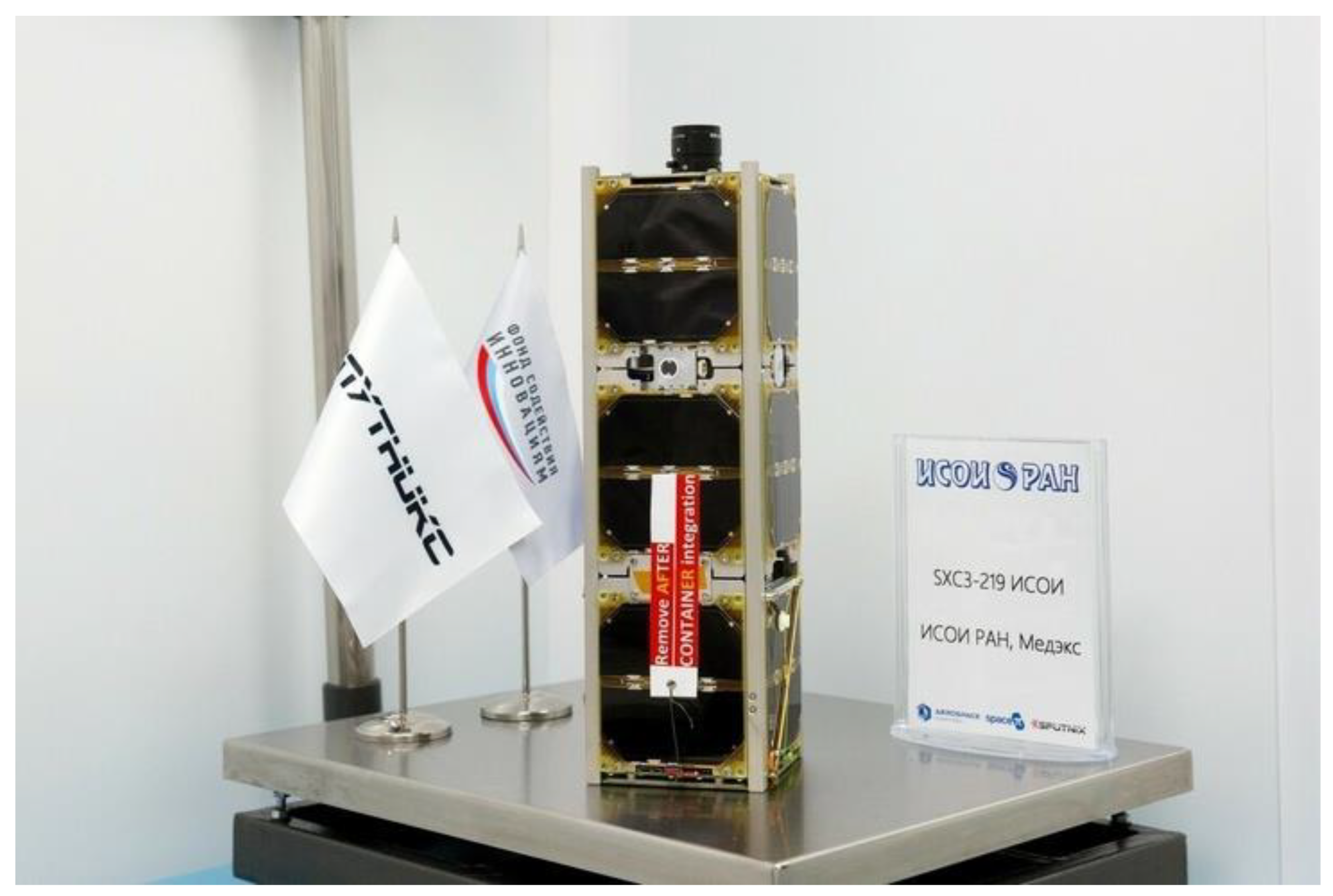
ISOI Small Spacecraft (SXC3-219) (
Figure 1) was launched on 09/8/22 from the Baikonur cosmodrome by a Soyuz-2.1b carrier rocket with a Fregat upper stage.
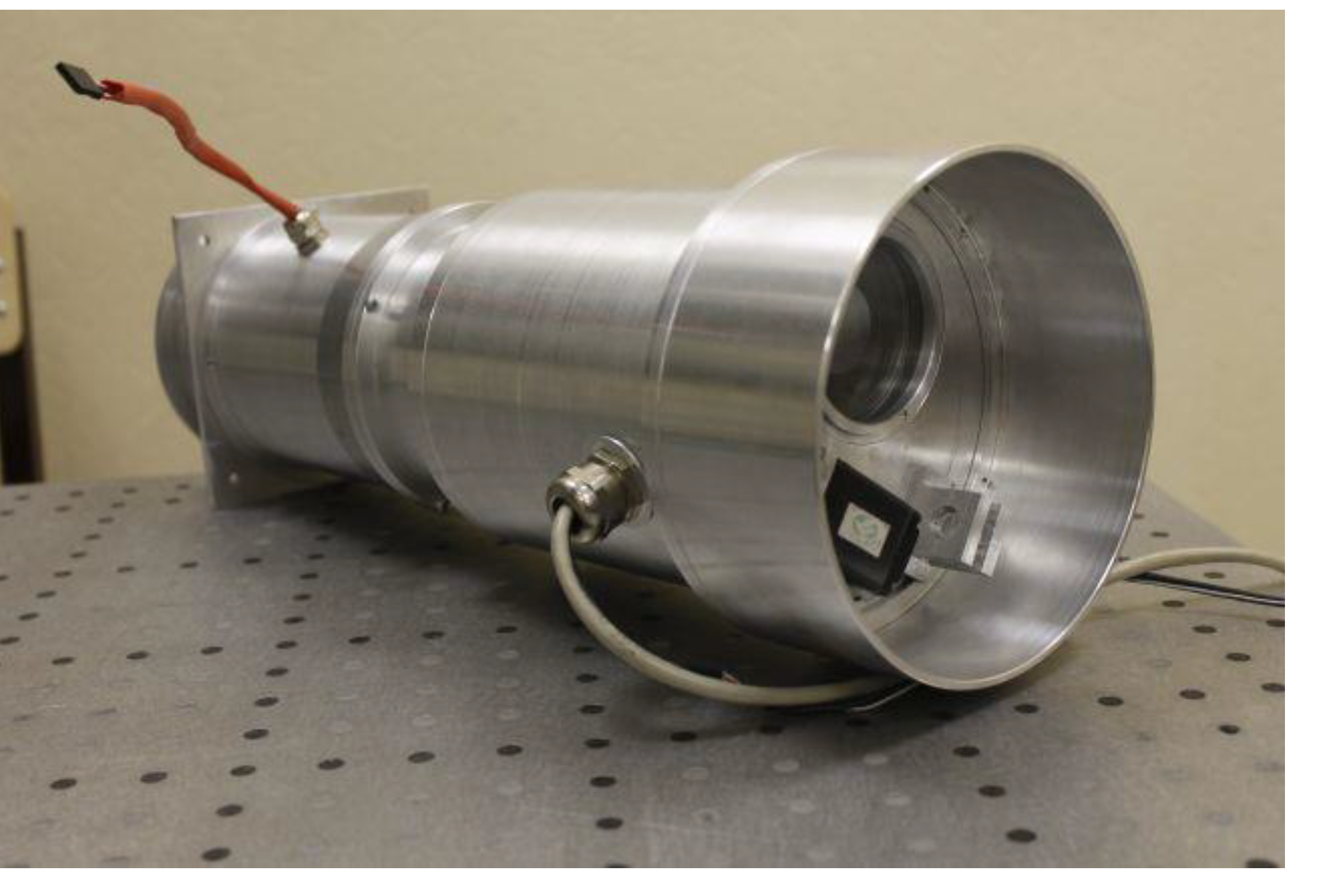
The small spacecraft is made on the OrbiCraft-Pro SXC3 platform of Sputnix. The payload, which weighs 3.471 kg, is a hyperspectral Earth remote sensing system. It is an imaging hyperspectrometer based on the Offner scheme for small spacecraft (
Figure 2 [
1]).
In the paper [
1], a new layout was proposed, which is based on the method of adaptive adjustment of the optical circuit depending on temperature by moving two optical elements of the system. These elements are axially located inside the hyperspectrometer. This arrangement allows the hyperspectrometer to operate in the temperature range from -40 to +45
oС without deterioration of optical characteristics. This makes it possible to use this system on board a small spacecraft.
Currently, small spacecraft are widely and successfully used to solve problems of remote sensing of the Earth. The paper [
2] presents the results and progress of flight tests of the small spacecraft for remote sensing of the Earth "Aist-2D". It is noted that this small spacecraft was created in the shortest possible time (less than three years) and can serve as an example of the successful implementation of the project of a modern multifunctional spacecraft for remote sensing of the Earth. he accumulated experience opens up opportunities for creating a series of spacecraft based on the "Aist-2" platform with minimal costs and short production times. The presented examples of using the obtained Earth remote sensing data to solve various tasks allow us to count on the creation of highly efficient space monitoring systems based on small spacecraft in the foreseeable future.
The paper [
3] sets out the principles to improve the sampling density and coverage of areas of the Earth's surface through the use of large groupings of small Earth remote sensing satellites. Performance indicators have been developed to characterize the key properties of the sample in numerical weather forecasting. Based on these indicators, the calculated parameters of the constellation orbit are optimized to develop optimized satellite configurations in low-orbit groupings in near-Earth orbit to maximize spatial and temporal sampling and coverage.
The paper [
4] is devoted to the analysis of innovative technological achievements used to create small satellites. New remote sensing capabilities based on numerous groupings of small satellites are considered to meet the needs for systematic continuous shooting with a minimum interval between images of any area of the Earth at a reasonable price.
In the paper [
5], the ways of development of small spacecraft for remote sensing of the Earth are predicted. It is noted that the first large groupings of small spacecraft (>100 satellites) are emerging. In the near future, all these small spacecraft will be interconnected and connected to the global Internet (IoT).
At the same time, the issues of improving the quality of remote sensing tasks are relevant [6, 7]. It is noted in the paper [
6] that the problem of data quality is becoming increasingly important in remote sensing due to the widespread use of digital services that use remote sensing data. The position of a group of experts from the Inter-Commission working group on data quality on the definition, classification and justification of issues that are considered key to the research program and the application of remote sensing is presented.
The authors of the paper [
7] believe that over the past two decades there has been a significant improvement in the quality of images using remote sensing spacecraft. The wide availability of images has allowed them to be used in many applications. However, as noted in [
7], image registration in remote sensing is a difficult task due to geometric differences between images and differences in intensity and influence of noise.
The paper [
8] notes the need for validation approaches to assess the quality of remote sensing data. Validation approaches use quality criteria in their evaluation. The analysis of how quality criteria are used in the life cycle of the remote sensing process is carried out. It is considered how quality criteria support solutions that determine the life cycle of the remote sensing process and correlate with the quality of the data itself.
The quality of remote sensing data is determined by:
- -
characteristics of the target equipment;
- -
the capabilities of the motion control system in stabilization mode;
- -
the quality of communication during the exchange of telemetry information and other factors.
Undoubtedly, the most important factor in the quality of remote sensing data is the capabilities of the target equipment itself. Therefore, the main direction towards improving data quality is to improve its characteristics [
9]. However, there are studies confirming the significant influence of the spacecraft motion control system in stabilization mode (for example, [10, 11]). It is noted in the paper [
10] that the spacecraft must ensure effective control of its orientation not only under the influence of external disturbances, but also with the relative movement of the target equipment. It is necessary to compensate for this movement in order to meet the requirements of precision guidance and stabilization of the spacecraft when performing target tasks.
The authors of the paper [
11] point to the continuous improvement of the characteristics of the target remote sensing equipment. This places increasing demands on the accuracy of orbit determination and the capabilities of the motion control system for Earth remote sensing spacecraft. This problem is especially relevant for a small spacecraft for remote sensing of the Earth [12, 13].
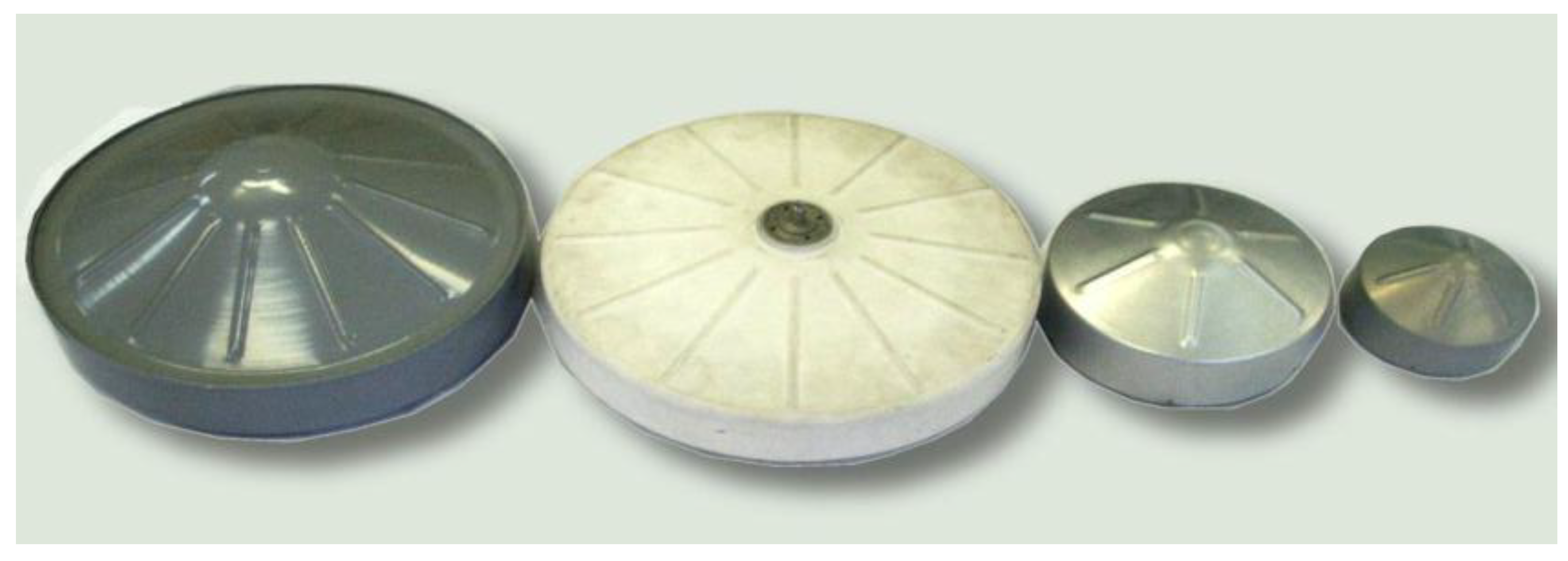
There are various methods for providing the required stabilization parameters for high-quality performance of Earth remote sensing tasks. They depend on the composition of the executive bodies of the motion control system. Currently, flywheel engines are most often used to solve orientation and stabilization problems on small spacecraft for remote sensing of the Earth (
Figure 3) [14, 15].
In the paper [
15], the influence of the number and location of flywheel engines on the quality of the target tasks is considered. The widespread use of flywheel engines is explained by the fact that they do not consume the working fluid [
16]. At the same time, they provide high stabilization accuracy [
17]. However, they periodically need to reduce their own kinetic moment when the maximum permissible angular velocity of rotation is reached [
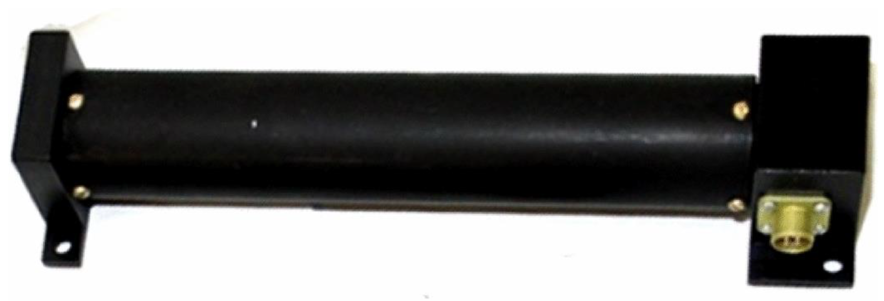
18]. Magnetic actuators can be used to solve target tasks not related to remote sensing (
Figure 4) [19, 20].
They don’t consume the working fluid and do not require unloading [21, 22]. However, the created control moment is always perpendicular to the induction vector of the Earth's magnetic field [
23]. At angular velocities greater than 5-10
0/s magnetic actuators become ineffective [
24].
A large number of works are devoted to the study of disturbing factors affecting a small spacecraft during its orbital flight. For example, in the paper [
19] the main external disturbing factors affecting its rotational motion around the center of mass in the illuminated and shadow sections of the orbit of the prototype small spacecraft "Aist" are considered. The possibility of reducing the angular velocity of rotation through the use of magnetic executive bodies has been studied (
Figure 4). In the paper [
15], the main disturbing factors were also studied, and a control system with four and eight flywheel engines was developed and tested. The efficiency of the control system with eight flywheel engines is shown. In the paper [
25] describes an approach to controlling the orientation of a small spacecraft based on the kinematic law of steering and servo subsystems. Modified Rodriguez parameters are used to describe the motion model taking into account perturbations. In the paper [
26], the problem of controlling the rotational motion of systems consisting of several spacecraft with specified characteristics in the presence of model uncertainties is investigated.
The evaluation of the parameters of the rotational motion of a small spacecraft can be carried out by various methods using various measuring instruments. Angular velocity sensors are considered the most reliable measuring instruments [2, 27]. However, the angular velocity is often estimated using data from measurements of the Earth's magnetic field [19, 28]. There are assessment methods related to the analysis of current data on current from solar panels [12, 29] or video surveillance cameras installed on a small spacecraft [
30]. All these methods have different accuracy and can be applied depending on the target tasks being solved and the requirements for the estimation error.
The issue of the accuracy of angular velocity estimates for many target tasks directly determines the quality of their implementation. Therefore, in this work, based on the analysis of measurement data of the components of the induction vector of the Earth's magnetic field by onboard magnetometers, the angular velocity is estimated and the methodological error of this estimate for the small ISOI spacecraft (SXC3-219) is investigated. Conclusions are drawn about the applicability of estimates in solving problems of remote sensing of the Earth.
Materials and Methods
The ISOI (SXC3-219) is considered as a small spacecraft in the paper (
Figure 1). The main characteristics of ISOI (SXC3-219) are given in
Table 1 [
31].
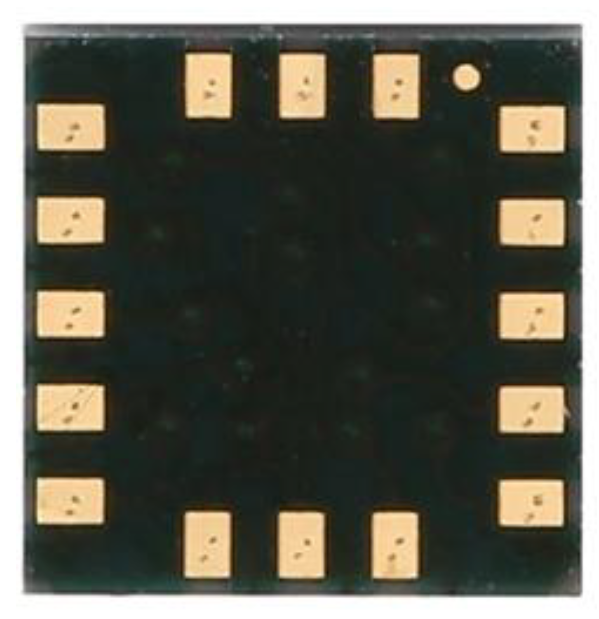
The ISOI small spacecraft (SXC3-219) is equipped with three-component MMC5983MA magnetometers (
Figure 5), the main characteristics of which are presented in
Table 2.
The angular velocity was estimated based on measurements of the components of the induction vector of the Earth's magnetic field in the construction coordinate system of the magnetometer according to the Boer formula [19, 32]:
where
и
– the components of the induction vector of the Earth's magnetic field, measured respectively at time
t0 and
t1 in the construction coordinate system of magnetometers,
– components of the angular velocity vector of rotation of a small spacecraft in the construction coordinate system of a magnetometer.
The estimate (1) doesn’t give a projection of the angular velocity onto the induction vector of the Earth's magnetic field. If one of the axes of the construction coordinate system coincides with the induction vector at some point in time, then the corresponding component of the angular velocity vector according to formula (1) will be zero. To solve this problem, it is proposed in [
33] to estimate the angular velocity of a small spacecraft using the derivative of the induction vector of the Earth's magnetic field:
where
и
– the components of the time derivative of the induction vector of the Earth's magnetic field, measured respectively at time points
t0 and
t1 in the construction coordinate system of magnetometers.
A combination of estimates (1) and (2) is used in this work to calculate the components of the angular velocity vector of the ISOI small spacecraft (SXC3-219).
Мetrological Measurement Model
For a correct assessment of the interpretation of the values of the angular velocity of rotation, we calculate the errors of its indirect measurements using (1) and (2). As shown by preliminary estimates [31, 34], the following errors are required to be taken into account:
- -
measuring error;
- -
methodological error;
- -
the dating error.
The measuring error of the MMC5983MA three-component magnetometer, taking into account the influence of the target and supporting equipment of the ISOI small spacecraft (SXC3-219), was estimated at± 1.5 μT (in the measurement range ± 400 μT, according to the passport of the measuring instrument). When comparing the results of indirect and direct measurements, a 3D Digital Angular Rate Sensor was used. Its measuring error is ± 0.1 deg/s (in the measurement range ± 245 deg/s, according to the passport of the measuring instrument). In the measured range of values, all measurement errors can be considered constant. The measurement error is considered additive.
For the methodological error in the estimation (1), it can written:
where
δB – the measurement error, which in this model is considered constant and the same for all three measurement channels.
In (3), the measurement error of the time interval is neglected in comparison with the measurement error of the components of the induction vector of the Earth's magnetic field. After simplifications and transformations (3), it is possible to obtain a simplified overestimation of the methodological error in the form of:
where
– the true values of the components of the angular velocity vector of a small spacecraft.
A more accurate estimate of the methodological error will look like:
The derivative of the components of the induction vector of the Earth's magnetic field is calculated using the difference formula:
where
i =
x,
y,
z;
j = 0, 1.
For the methodological error in the estimation (2), it can written:
where
– the components of the induction vector of the Earth's magnetic field, measured at time
t-1, preceding
t0;
– the methodological error of the difference formula (6).
It should be noted that the metrological model of the methodological error (7) is significantly more complicated than (5). In formula (7)
depends on how intensively the component of the induction vector changes in the area between two consecutive measurements. Therefore, it is incorrect to consider this error as a constant in the general case. It is a function of time and depends on the magnitude of the measurement step. With a uniform measurement step (
)and small values of this step (
) formula (7) can be simplified:
For a comparative analysis of estimation errors using different methods (1) and (2), it can be assumed that
and denote
. Then (8) is reduced to the following form:
Equations (9) are completely structurally consistent with Equation (3). This allows for a comparative analysis of estimation errors using different methods (1) and (2). It is easy to see that
. Even more so
. Therefore, the variance of the estimate (2) will always be higher than the estimates (1). In general, these estimates will not be equivalent. Similarly (5), an estimate of the methodological error can be written for (9):
Thus, the methodological error of both methods for estimating the angular velocity of rotation of a small spacecraft is estimated.
Verification of the Metrological Measurement Model
To verify the metrological model and build a statistical model for estimating the angular velocity of rotation of the ISOI small spacecraft (SXC3-219), various measurement sites and various orientation modes were selected. A 3D Digital Angular Rate Sensor was used to estimate the errors of indirect measurements of the components of the angular velocity of rotation of a small spacecraft using methods (1) and (2) (
Figure 6).
The instrument coordinate system of the 3D Digital Angular Rate Sensor (
Figure 6) coincides with the instrument coordinate system of the MMC5983MA three-component magnetometer (
Figure 5). To obtain comparable results, all measurements are carried out in the instrument coordinate system, and then recalculated into a movable coordinate system, the x-axis of which is directed along the vector of induction of the Earth's magnetic field. As mentioned above, the estimate (1) gives only two components of the angular velocity vector of the small spacecraft. The projection of the angular velocity on the direction of the magnetic induction vector using the estimate (1) will always be zero. Since this estimate is based on a vector product
[
32].
In fact, we are talking about verifying the error estimation using metrological reference tests. The 3D Digital Angular Rate Sensor is taken as the standard as a more accurate measuring instrument compared to the three-component MMC5983MA magnetometer. Verification is carried out according to the classical scheme described in [35, 36], under various observation conditions. The differences in these conditions are determined by the different modes of operation of the ISOI small spacecraft (SXC3-219).
This mode is characterized by a complete absence of control actions on a small spacecraft. The targets are not fulfilled. The supporting equipment and measuring instruments are working.
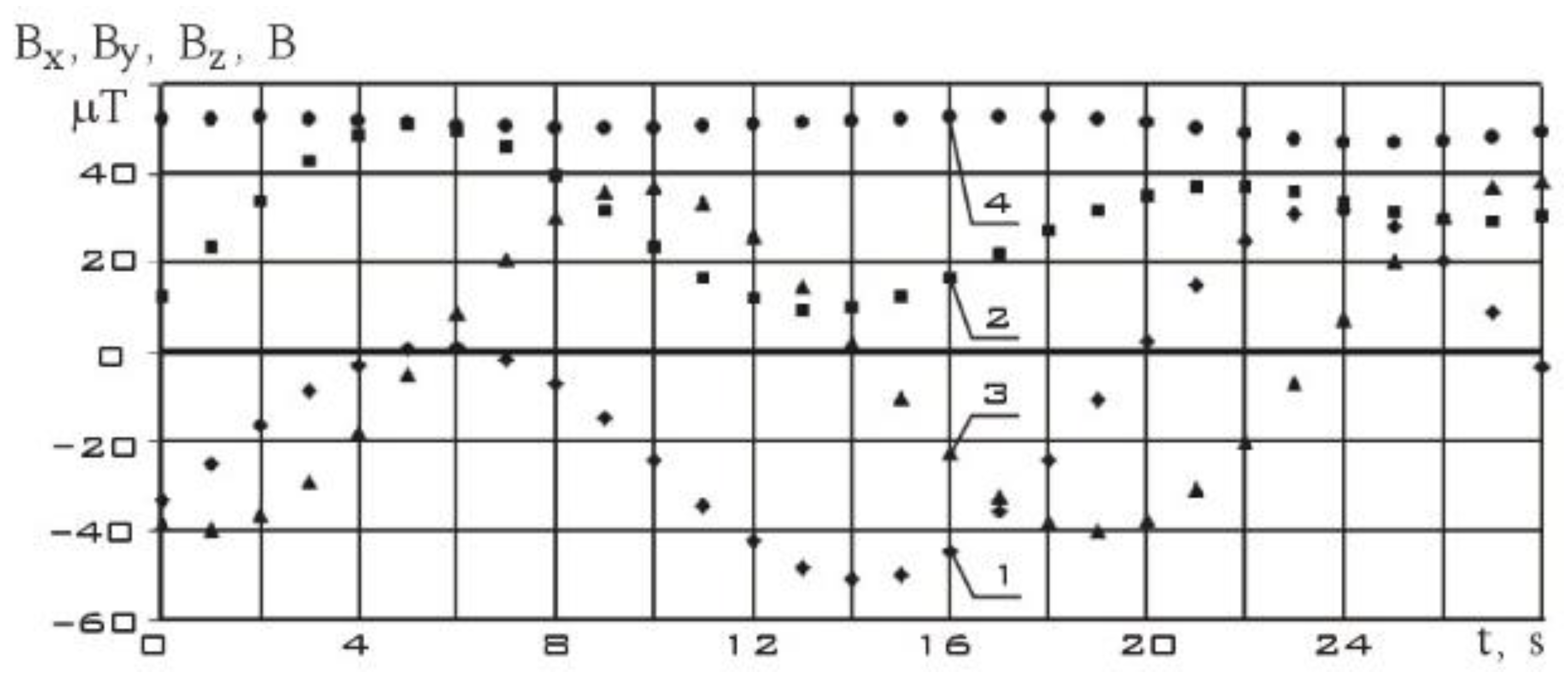
Consider the measurement section from 06/05/2023. It contains 15 measurements starting at 12:54:36.969 Moscow time with a uniform measurement step
.
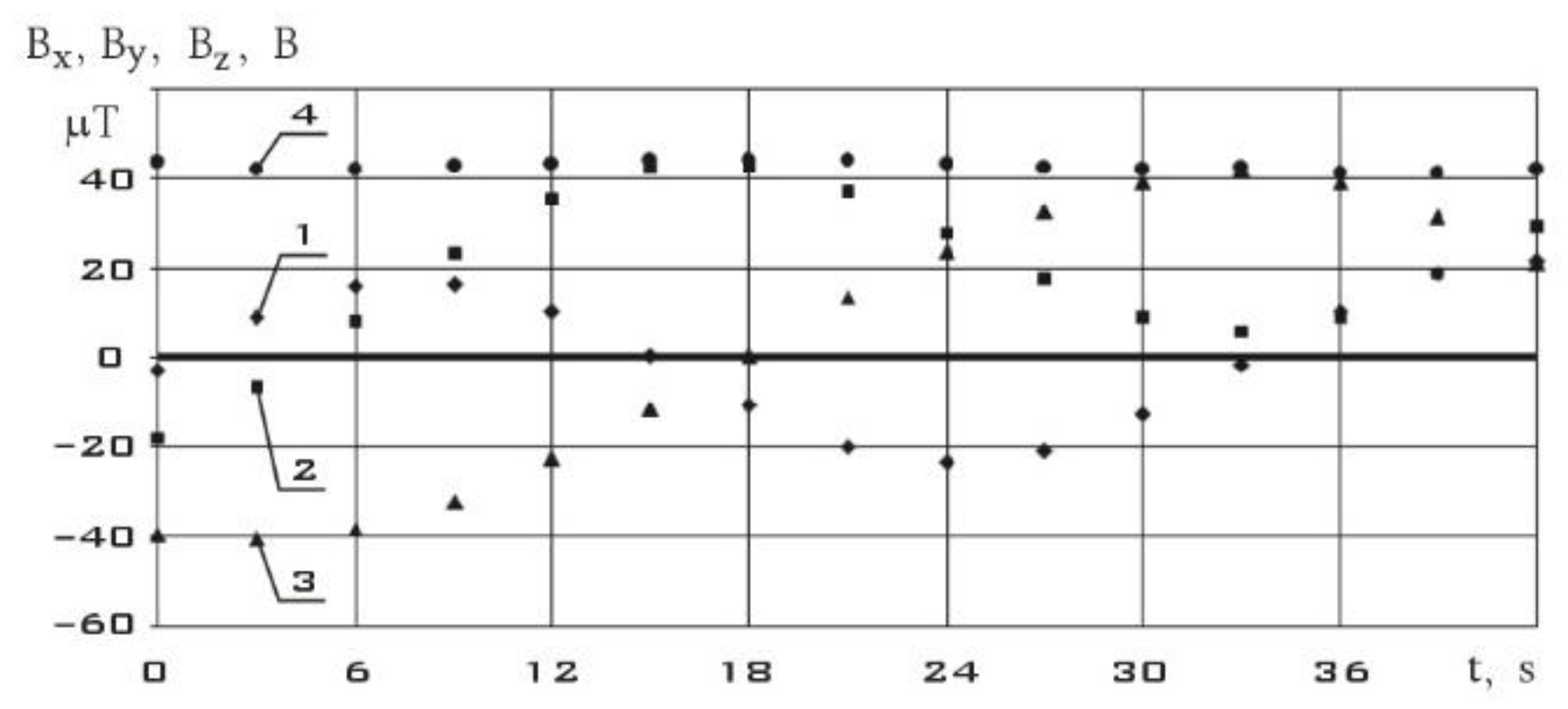
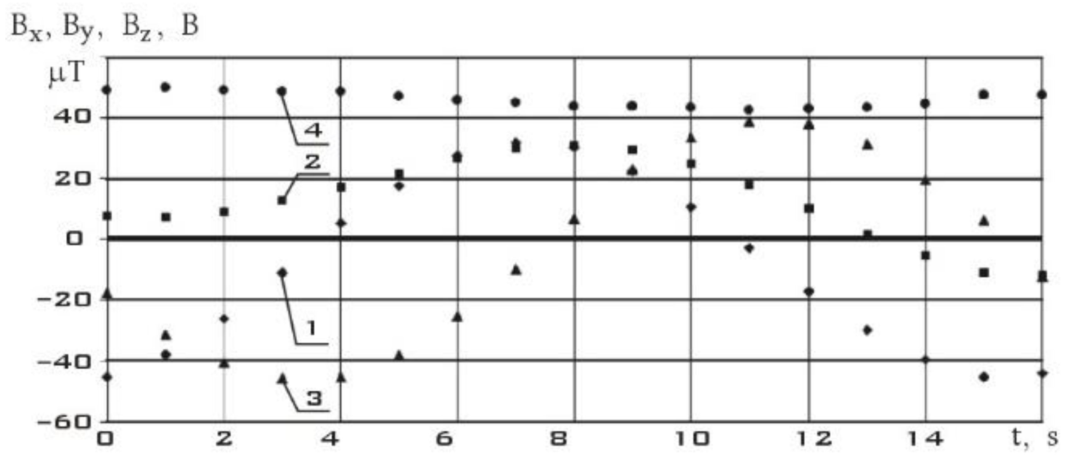
Figure 7 shows measurements of the components of the Earth's magnetic field induction vector in the instrument coordinate system of the MMC5983MA three-component magnetometer. As can be seen from
Figure 7, the modulus of the magnetic induction vector practically doesn’t change during measurements. Changes in its components are mainly due to the rotation of a small spacecraft. In
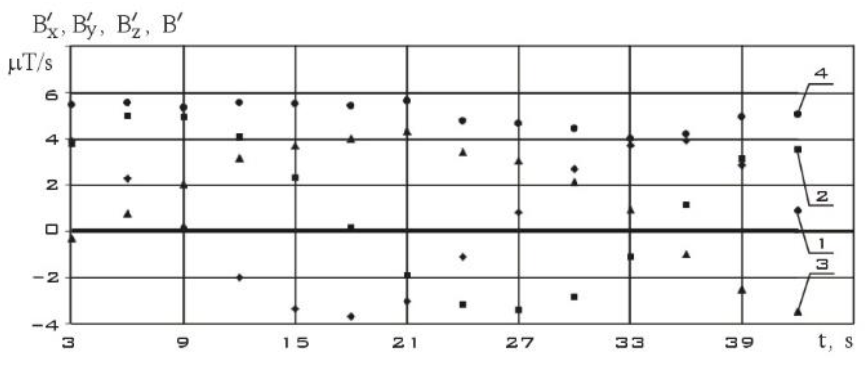
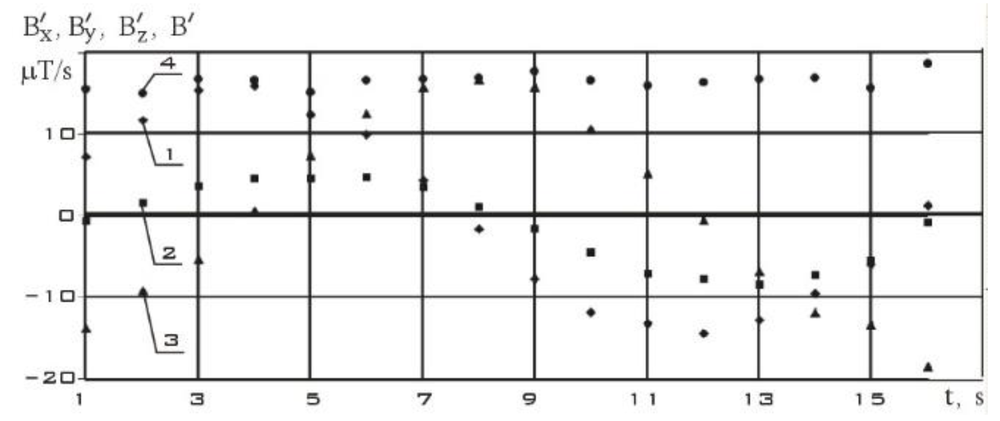
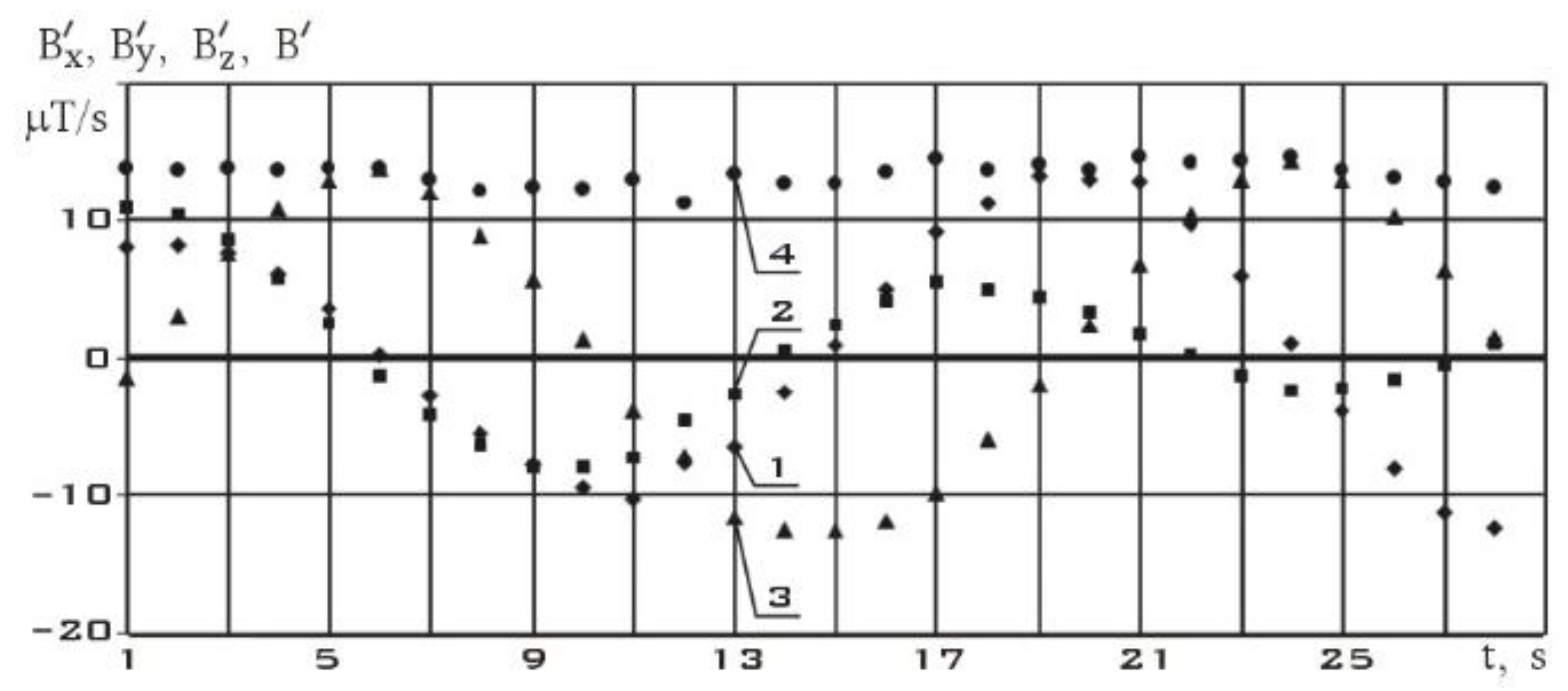
Figure 8, using the difference formula (6), the components of the local derivative of the induction vector of the Earth's magnetic field are estimated.
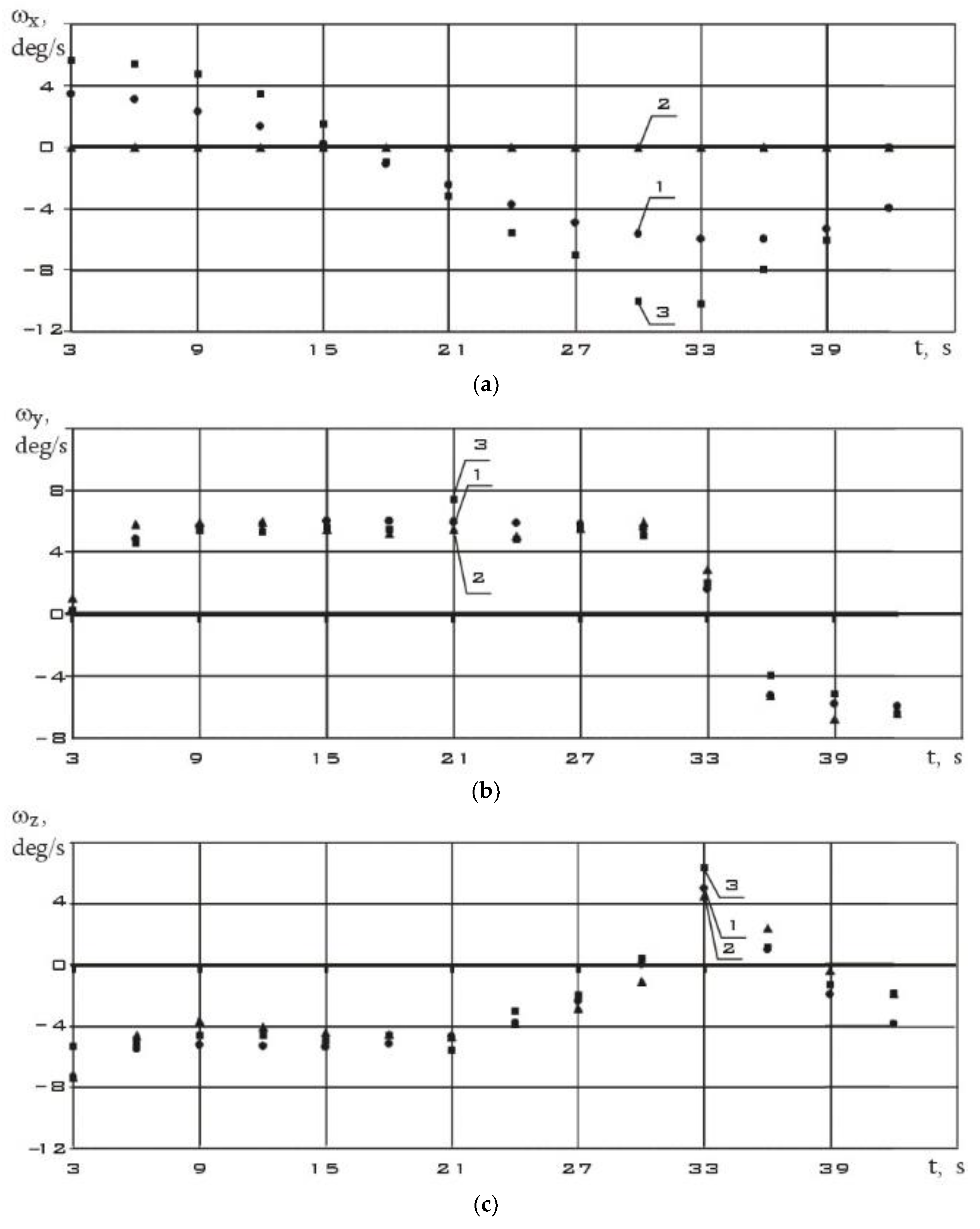
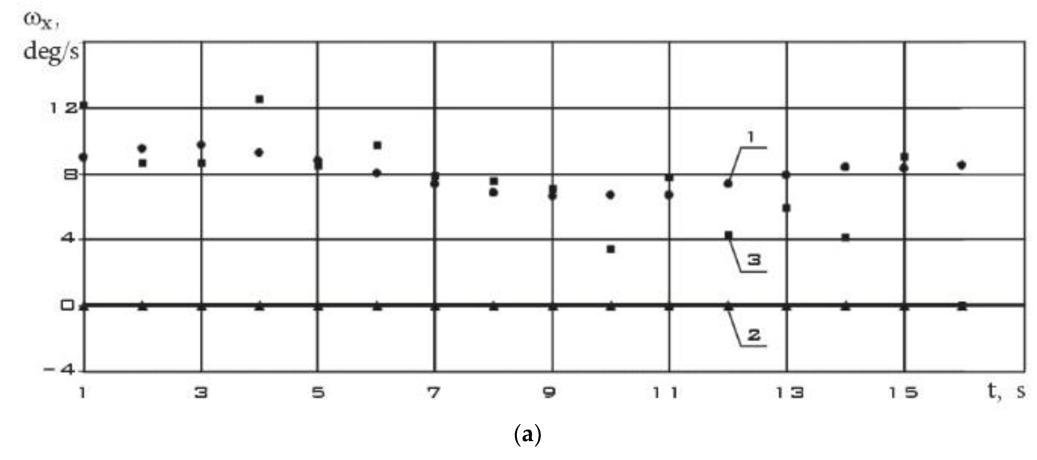
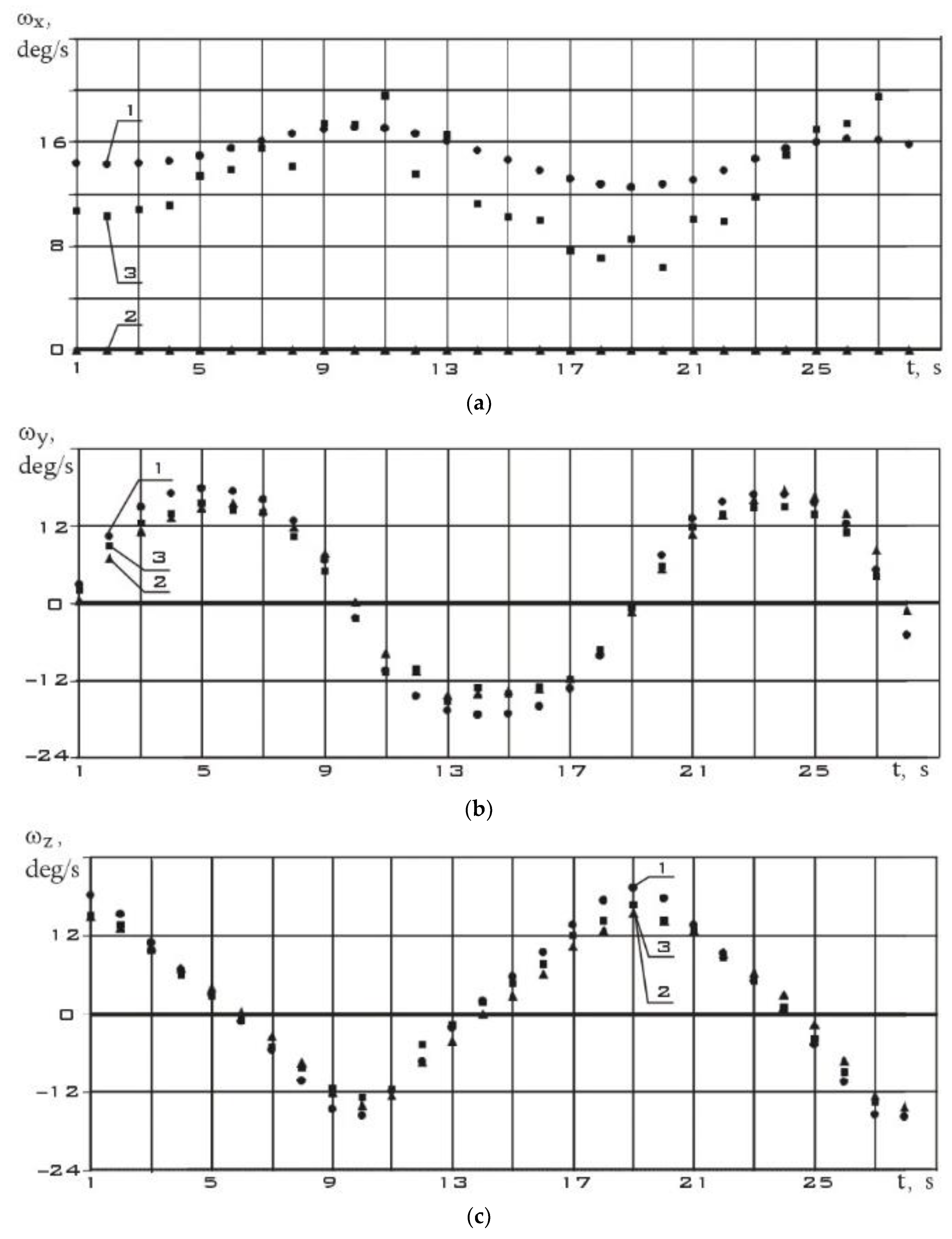
Further, the axes of the instrument coordinate system were rotated so that the x axis coincided with the direction of the induction vector of the Earth's magnetic field. And in this coordinate system, the components of the angular velocity vector of the ISOI small spacecraft (SXC3-219) were determined using estimates (1) and (2), as well as measurements of the 3D Digital Angular Rate Sensor. These results are shown in
Figure 9.
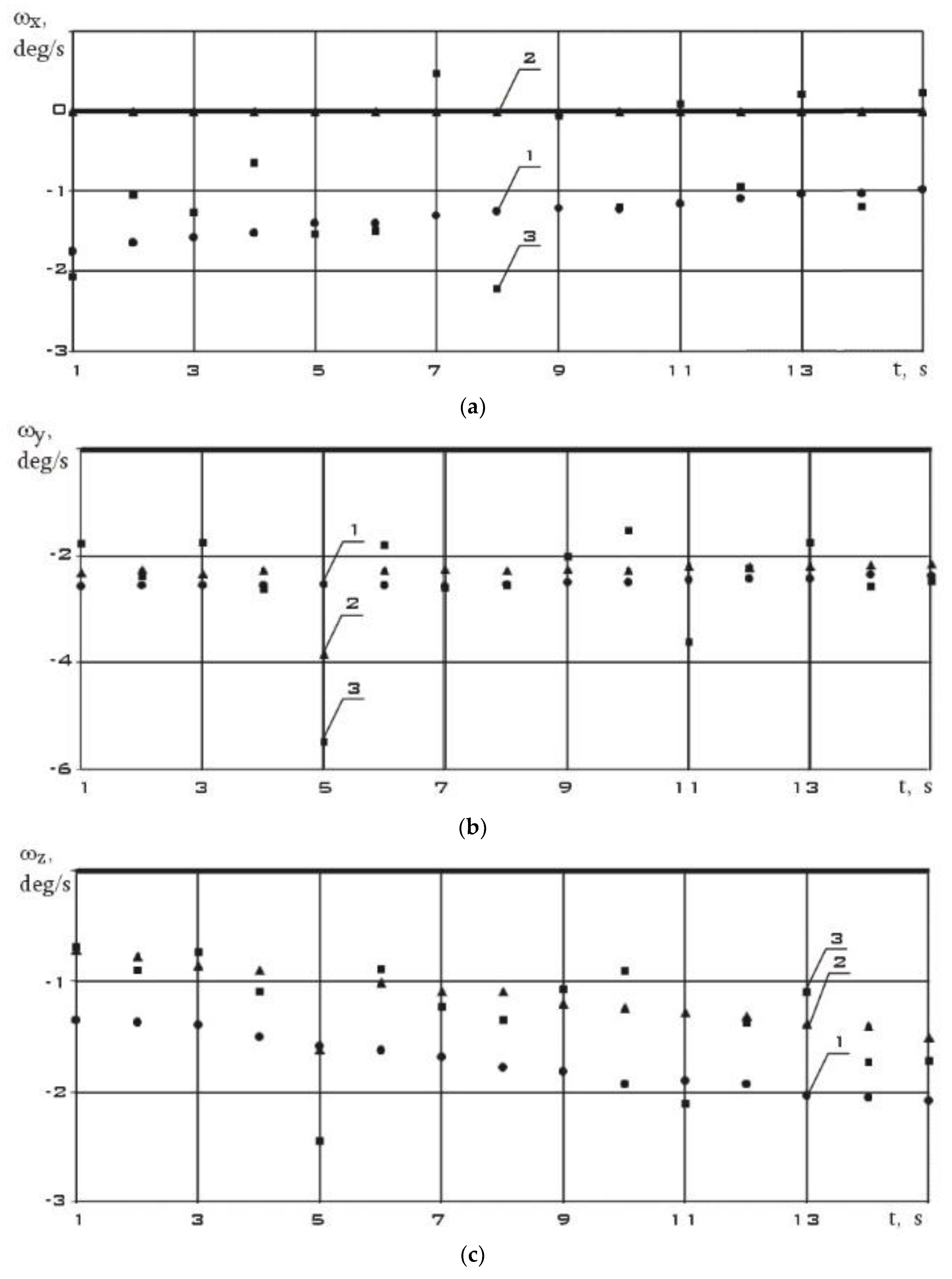
We will reduce the interval between measurements by three times. Consider the measurement section from 09/12/2023. It contains 17 measurements starting at 11:21:59.887 Moscow time with a uniform measurement step .
Figure 10 shows measurements of the components of the Earth's magnetic field induction vector in the instrument coordinate system of the MMC5983MA three-component magnetometer. As in
Figure 7, the modulus of the magnetic induction vector practically doesn’t change during measurements. In
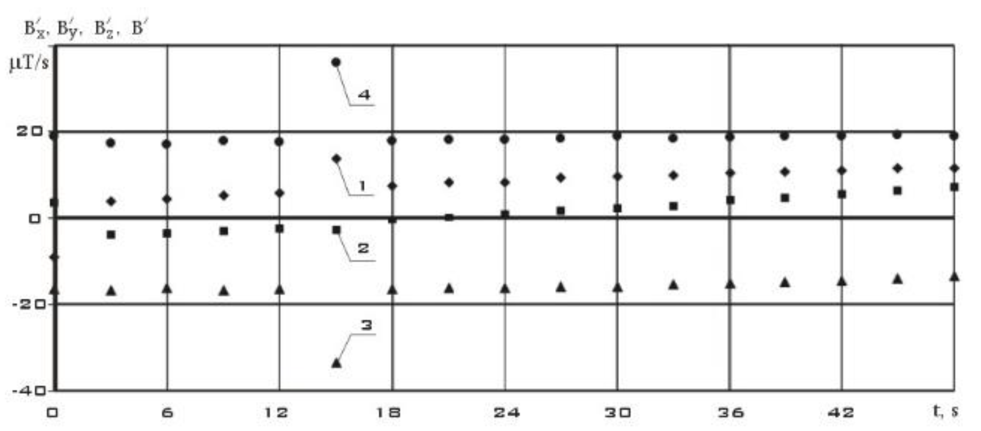
Figure 11, using the difference formula (6), the components of the local derivative of the induction vector of the Earth's magnetic field are estimated.
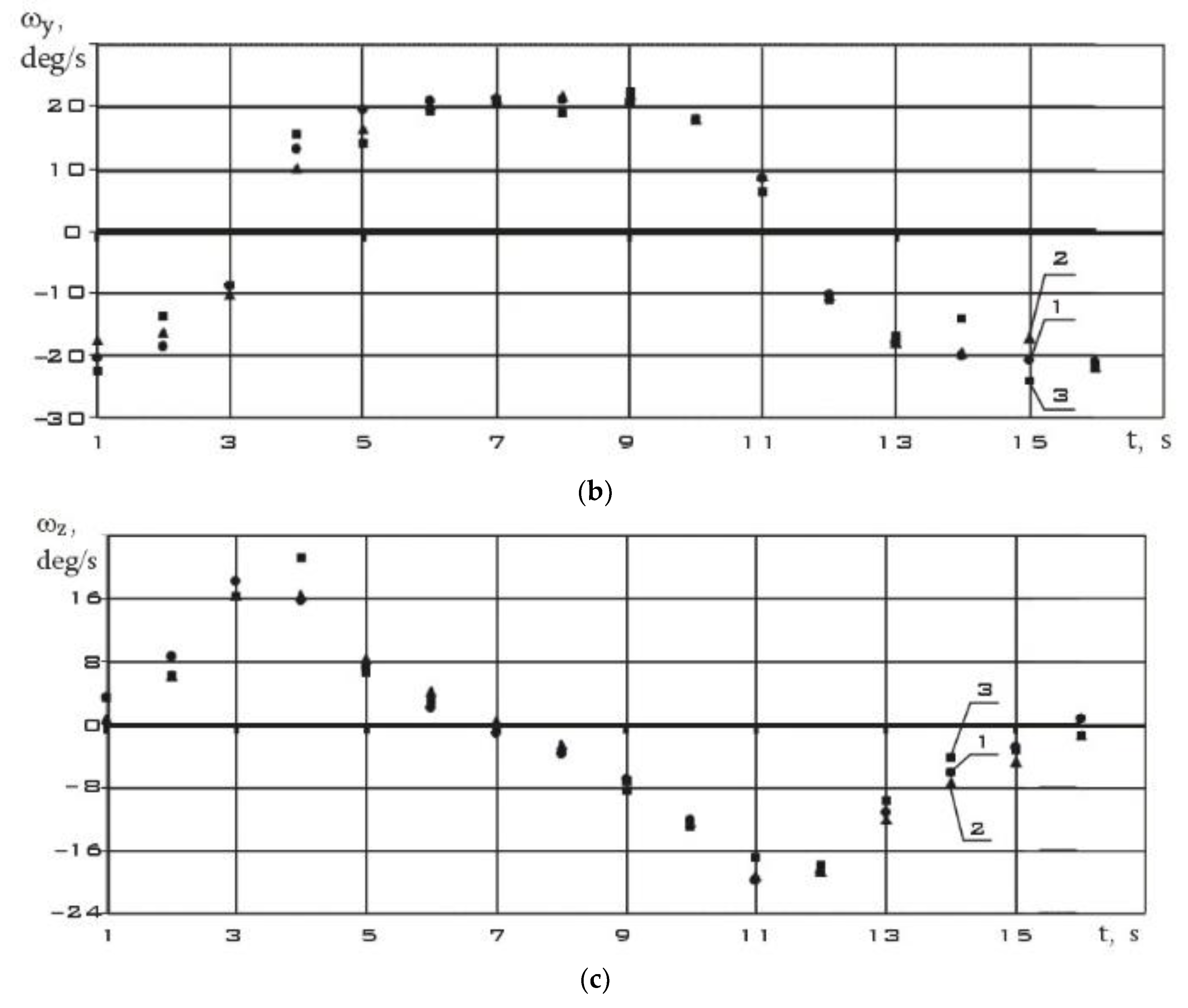
The components of the angular velocity vector were determined in a coordinate system whose x-axis coincides with the direction of the induction vector of the Earth's magnetic field. These results are shown in
Figure 12.
The analysis of the presented dependencies shows that when the measurement step is reduced from 3 s to 1 s, the difference between estimates (1) and (2) decreases. This is expected. Since the derivative over a shorter time interval is determined using the difference formula (6) more precisely.
- 2.
The mode of reducing the angular velocity of the ISOI small spacecraft (SXC3-219) by magnetic actuators.
This mode is characterized by the effect on a small spacecraft of a control moment from magnetic actuators to reduce the angular velocity of its rotation. In this mode, the target tasks are not solved. The supporting systems, measuring instruments and magnetic executive bodies are working. The algorithm of operation of magnetic executive bodies is the well–known and widely used in practice algorithm “–Bdot” [19-21].
Consider the measurement section from 09/24/2023. It contains 29 measurements starting at 10:05:30.869 Moscow time with a uniform measurement step .
Figure 13 shows measurements of the components of the Earth's magnetic field induction vector in the instrument coordinate system of the MMC5983MA three-component magnetometer. As in
Figure 7 and
Figure 10, the modulus of the magnetic induction vector practically doesn’t change during measurements.
In
Figure 14, using the difference formula (6), the components of the local derivative of the induction vector of the Earth's magnetic field are estimated.
The components of the angular velocity vector were determined in a coordinate system whose x-axis coincides with the direction of the induction vector of the Earth's magnetic field. These results are shown in
Figure 15.
- 3.
The mode of orbital orientation of the ISOI small spacecraft (SXC3-219) by flywheel engines.
This mode is characterized by the controlling effect on the small spacecraft of the main executive bodies of the motion control system. For the ISOI small spacecraft (SXC3-219) such executive bodies are flywheel engines (
Figure 3). In this mode, the lowest angular velocity of rotation is achieved and the target tasks of remote sensing of the Earth are solved.
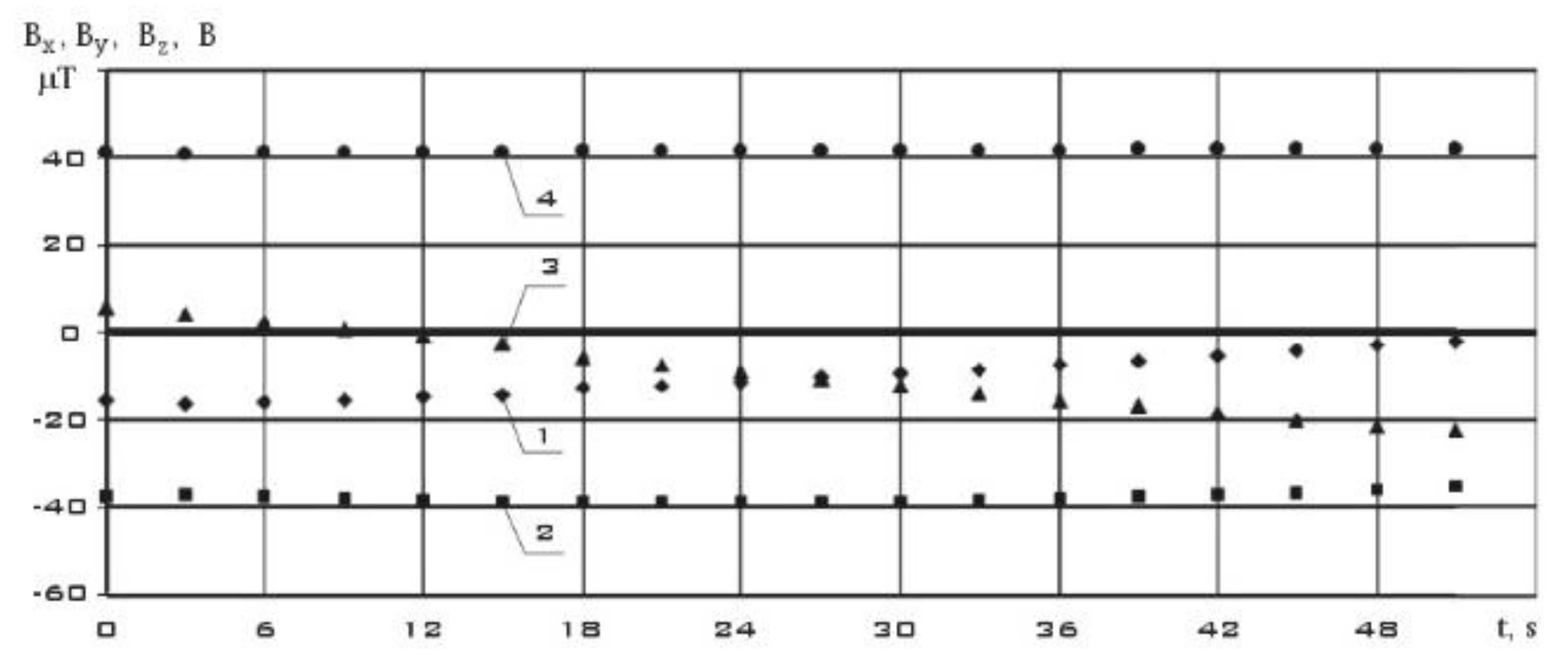
Consider the measurement section from 02/17/2024. It contains 18 measurements starting at 12:29:48.132 Moscow time with a uniform measurement step.
Figure 16 shows measurements of the components of the Earth's magnetic field induction vector in the instrument coordinate system of the MMC5983MA three-component magnetometer.
Unlike
Figure 7,
Figure 10 and
Figure 13, not only the modulus of the induction vector of the Earth's magnetic field is constant here, but also its components. This indicates low values of the angular velocity of rotation of the small ISOI spacecraft (SXC3-219) in this area. In
Figure 17, using the difference formula (6), the components of the local derivative of the induction vector of the Earth's magnetic field are estimated.
The values of the derived components of the Earth's magnetic field induction vector for the orbital orientation mode are significantly lower than for other operating modes of the ISOI small spacecraft (SXC3-219) (
Figure 8,
Figure 11 and
Figure 14). At the same time, their changes are also significantly less significant than for other modes (
Figure 8,
Figure 11 and
Figure 14). The components of the angular velocity vector were determined in a coordinate system whose x-axis coincides with the direction of the induction vector of the Earth's magnetic field. These results are shown in
Figure 18:
In addition to these measurement sites, other sites were investigated. The main data of the verification of the model of the methodological error of the angular velocity estimation are presented in
Table 3.
Explanations of
Table 3: Δ
t – uniform measurement step over time;
– the modulus of the average value of the angular velocity in the measurement area; δ
ω(5) – the maximum value of the methodological error of the assessment (1) in the considered measurement area, estimated by the formula (5); δ
ω(10) – the maximum value of the methodological error of the assessment (2) in the considered measurement area, estimated by the formula (10);
N0 – the total number of measurements taking into account all three components of the Earth's magnetic field induction vector and the angular velocity vector of the small spacecraft;
N5 – the total number of estimates of angular velocity (1) with a discrepancy is greater than the sum of the maximum methodological error (δ
ω(5)) and the measurement error of the 3D Digital Angular Rate Sensor;
N10 – the total number of estimates of angular velocity (2) with a discrepancy is greater than the sum of the maximum methodological error (δ
ω(10)) and the measurement error of the 3D Digital Angular Rate Sensor; δ
ωmax(5) – the maximum value of the estimation discrepancy (1) relative to direct measurements in the considered measurement area; δ
ωmax(10) – the maximum value of the estimation discrepancy (2) relative to direct measurements in the considered measurement area.
Discussion of the Results: Conclusion
In the theory of metrological tests of measuring instruments [36-39], the estimation of error and its probabilistic characteristics using metrological tests causes the following error:
where
– methodological error (error of imperfection of models);
– error of finiteness of the volume of the sample used;
– measurement error (error of difference between the real value and the true one);
– error of transformations.
In fact, the values of δω(5) and δω(10) are approximate estimates of the maximum likelihood of the mathematical expectation of a sample random variable
. These values are the point estimates of the error
(11). From the approximate formulas (5) and (10), the probabilistic characteristics of these estimates for various measurement segments were obtained. The results are presented in
Table 3.
During validation based on the results of metrological reference tests, it was found that approximate formulas (5) and (10) can be used to estimate errors in calculating angular velocity based on measurements of the components of the induction vector of the Earth's magnetic field. Formulas (1) give more accurate estimates of the components of the angular velocity vector. However, they can be used to evaluate only two of the three components.
It is established that the probabilistic characteristics of the error depend on the magnitude of the angular velocity modulus at the measurement site. As the angular velocity modulus increases, the sampling average and the sampling variance of the error increase. In addition, the probabilistic characteristics of the error are influenced by the magnitude of the angular velocity modulus at the measurement site. A larger scale corresponds to a larger value of the error variance. The estimation (2) is significantly more sensitive to the influence of the intrinsic magnetic field of the magnetic executive bodies than the estimation (1). In the "–Bdot" mode, the estimation (2) may be inadequate due to the operation of magnetic executive bodies that create their own magnetic field. At the same time, the accuracy of measuring the components of the induction vector of the Earth's magnetic field deteriorates. The evaluation of the derivative according to formula (6) deteriorates even more. In the orbital orientation mode, with a low angular velocity of rotation of the spacecraft, the methodological error becomes high due to neglect of the absolute derivative of the induction vector of the Earth's magnetic field. In this case, the interval between measurements of 1s is apparently large in order to correctly neglect this absolute derivative. These facts certainly require separate statistical studies, which are beyond the scope of this paper.
Thus, the paper builds a model for estimating the methodological error in calculating the angular velocity based on on-board measurements of the induction vector of the Earth's magnetic field for two different estimation methods. Verification of the constructed model was carried out on the small ISOI spacecraft (SXC3-219) using reference metrological tests. The results of the work can be used to study the dynamics of the rotational motion of the spacecraft.
Figure 1.
The exterior of the ISOI Small Earth Remote Sensing Spacecraft (SXC3-219).
Figure 1.
The exterior of the ISOI Small Earth Remote Sensing Spacecraft (SXC3-219).
Figure 2.
The appearance of the hyperspectrometer (quoted from [
1]).
Figure 2.
The appearance of the hyperspectrometer (quoted from [
1]).
Figure 3.
The appearance of flywheel engines (quoted from [
14]).
Figure 3.
The appearance of flywheel engines (quoted from [
14]).
Figure 4.
The appearance of the magnetic executive body (quoted from [
19]).
Figure 4.
The appearance of the magnetic executive body (quoted from [
19]).
Figure 5.
The appearance of the MMC5983MA three-component magnetometer.
Figure 5.
The appearance of the MMC5983MA three-component magnetometer.
Figure 6.
The appearance of 3D Digital Angular Rate Sensor.
Figure 6.
The appearance of 3D Digital Angular Rate Sensor.
Figure 7.
The measurements of the components of the Earth's magnetic field induction vector in the instrument coordinate system of the MMC5983MA three-component magnetometer from 06/05/2023 (t = 0 corresponds to 12:54:36.969 Moscow time).
Figure 7.
The measurements of the components of the Earth's magnetic field induction vector in the instrument coordinate system of the MMC5983MA three-component magnetometer from 06/05/2023 (t = 0 corresponds to 12:54:36.969 Moscow time).
Figure 8.
The estimation of the components of the local derivative of the Earth's magnetic field induction vector in the instrument coordinate system of the MMC5983MA three-component magnetometer from 06/05/2023 (t = 0 corresponds to 12:54:36.969 Moscow time).
Figure 8.
The estimation of the components of the local derivative of the Earth's magnetic field induction vector in the instrument coordinate system of the MMC5983MA three-component magnetometer from 06/05/2023 (t = 0 corresponds to 12:54:36.969 Moscow time).
Figure 9.
The estimation of the components of the angular velocity vector using (1) and (2), as well as their direct measurements from 06/05/2023 (t = 0 corresponds to 12:54:36.969 Moscow time).
Figure 9.
The estimation of the components of the angular velocity vector using (1) and (2), as well as their direct measurements from 06/05/2023 (t = 0 corresponds to 12:54:36.969 Moscow time).
Figure 10.
– T he measurements of the components of the Earth's magnetic field induction vector in the instrument coordinate system of the MMC5983MA three-component magnetometer from 09/12/2023 (t = 0 corresponds to 11:21:59.887 Moscow time).
Figure 10.
– T he measurements of the components of the Earth's magnetic field induction vector in the instrument coordinate system of the MMC5983MA three-component magnetometer from 09/12/2023 (t = 0 corresponds to 11:21:59.887 Moscow time).
Figure 11.
The estimation of the components of the local derivative of the Earth's magnetic field induction vector in the instrument coordinate system of the MMC5983MA three-component magnetometer from 09/12/2023 (t = 0 corresponds to 11:21:59.887 Moscow time).
Figure 11.
The estimation of the components of the local derivative of the Earth's magnetic field induction vector in the instrument coordinate system of the MMC5983MA three-component magnetometer from 09/12/2023 (t = 0 corresponds to 11:21:59.887 Moscow time).
Figure 12.
The estimation of the components of the angular velocity vector using (1) and (2), as well as their direct measurements from 09/12/2023 (t = 0 corresponds to 11:21:59.887 Moscow time).
Figure 12.
The estimation of the components of the angular velocity vector using (1) and (2), as well as their direct measurements from 09/12/2023 (t = 0 corresponds to 11:21:59.887 Moscow time).
Figure 13.
The measurements of the components of the Earth's magnetic field induction vector in the instrument coordinate system of the MMC5983MA three-component magnetometer from 09/24/2023 (t = 0 corresponds to 10:05:30.869 Moscow time).
Figure 13.
The measurements of the components of the Earth's magnetic field induction vector in the instrument coordinate system of the MMC5983MA three-component magnetometer from 09/24/2023 (t = 0 corresponds to 10:05:30.869 Moscow time).
Figure 14.
The estimation of the components of the local derivative of the Earth's magnetic field induction vector in the instrument coordinate system of the MMC5983MA three-component magnetometer from 09/24/2023 (t = 0 corresponds to 10:05:30.869 Moscow time).
Figure 14.
The estimation of the components of the local derivative of the Earth's magnetic field induction vector in the instrument coordinate system of the MMC5983MA three-component magnetometer from 09/24/2023 (t = 0 corresponds to 10:05:30.869 Moscow time).
Figure 15.
The estimation of the components of the angular velocity vector using (1) and (2), as well as their direct measurements from 09/24/2023 (t = 0 corresponds to 10:05:30.869 Moscow time).
Figure 15.
The estimation of the components of the angular velocity vector using (1) and (2), as well as their direct measurements from 09/24/2023 (t = 0 corresponds to 10:05:30.869 Moscow time).
Figure 16.
The measurements of the components of the Earth's magnetic field induction vector in the instrument coordinate system of the MMC5983MA three-component magnetometer dated 02/17/2024 (t = 0 corresponds to 12:29:48.132 Moscow time).
Figure 16.
The measurements of the components of the Earth's magnetic field induction vector in the instrument coordinate system of the MMC5983MA three-component magnetometer dated 02/17/2024 (t = 0 corresponds to 12:29:48.132 Moscow time).
Figure 17.
The estimation of the components of the local derivative of the Earth's magnetic field induction vector in the instrument coordinate system of the MMC5983MA three-component magnetometer dated 02/17/2024 (t = 0 corresponds to 12:29:48.132 Moscow time).
Figure 17.
The estimation of the components of the local derivative of the Earth's magnetic field induction vector in the instrument coordinate system of the MMC5983MA three-component magnetometer dated 02/17/2024 (t = 0 corresponds to 12:29:48.132 Moscow time).
Figure 18.
The estimation of the components of the angular velocity vector using (1) and (2), as well as their direct measurements from 02/17/2024 (t=0 corresponds to 12:29:48.132 Moscow time).
Figure 18.
The estimation of the components of the angular velocity vector using (1) and (2), as well as their direct measurements from 02/17/2024 (t=0 corresponds to 12:29:48.132 Moscow time).
Table 1.
The main characteristics of the ISOI small spacecraft ISOI (SXC3-219) [
31].
Table 1.
The main characteristics of the ISOI small spacecraft ISOI (SXC3-219) [
31].
| Parameter |
Value |
Dimension |
| Mass |
5.5 |
kg |
| Overall dimensions |
0.11х0.11х0.34 |
m |
| Medium-turn energy capacity |
0.9 |
W |
| Orientation accuracy |
5 |
deg |
| The number of executive bodies of the motion control system - engines-flywheels |
4 |
- |
| The height of the circumferential orbit |
485 |
км |
| Inclination of the circumferential orbit |
97.5 |
deg |
| Guaranteed period of active existence |
9 |
month |
| Build Date |
14.07.22 |
|
| Launch date |
09.08.22 |
|
Table 2.
The main characteristics of the MMC5983MA three-component magnetometer.
Table 2.
The main characteristics of the MMC5983MA three-component magnetometer.
| Parameter |
Value |
Dimension |
| Overall dimensions |
3.0х3.0х1.0 |
mm |
| Field Range (Each Axis) |
±8 |
G |
| Orientation accuracy |
0.5 |
deg |
| Linearity Error |
0.1 |
%FS |
| Maximal Total RMS Noise |
1.2 |
G |
| Null Field Output |
±0.5 |
G |
| Output Resolution |
18 |
Bits |
| Operating temperature range |
-40...+105 |
oC |
| Max Output data rate |
1000 |
Hz |
Table 3.
The final verification table.
Table 3.
The final verification table.
Parameter
Date |
, deg/s |
Δt, s |
δω(5), deg/s |
δω(10), deg/s |
N0
|
N5
|
N10
|
δωmax(5), deg/s |
δωmax(10), deg/s |
| Undirected flight mode |
21.06.2023
10:19:58.262–10:21:25.167 |
7.10 |
3 |
1.0 ±0.3 |
1.5 ±0.6 |
90 |
3 |
10 |
1.4 |
4.9 |
05.06.2023
12:54:36.969–12:55:18.973 |
7.99 |
3 |
1.0 ±0.3 |
1.5 ±0.6 |
45 |
4 |
5 |
1.9 |
4.3 |
25.05.2023
11:06:19.714–11:07:10.712 |
8.18 |
3 |
1.1 ±0.3 |
1.4 ±0.6 |
48 |
1 |
11 |
1.7 |
4.0 |
07.05.2024
12:21:52.166–12:23:46.105 |
8.7 |
3 |
1.5 ±0.4 |
2.0 ±0.7 |
117 |
7 |
11 |
2.5 |
4.4 |
04.05.2024
12:58:21.902–12:59:10.192 |
8.74 |
3 |
1.2 ±0.3 |
1.6 ±0.7 |
42 |
1 |
3 |
2.3 |
3.2 |
04.05.2024
13:02:28.068–13:03:22.020 |
9.17 |
3 |
1.5 ±0.5 |
2.0 ±0.9 |
57 |
1 |
3 |
2.2 |
8.4 |
07.05.2024
12:25:13.366–12:25:58.341 |
9.9 |
3 |
1.6 ±0.5 |
2.4 ±1.0 |
48 |
1 |
4 |
2.3 |
4.4 |
04.05.2024
12:58:21.902–12:59:10.192 |
12.4 |
3 |
2.3 ±0.8 |
3.1 ±1.1 |
51 |
2 |
3 |
3.4 |
7.1 |
04.05.2024
01:09:35.460–01:10:21.527 |
4.64 |
1 |
0.6 ±0.2 |
1.5 ±0.5 |
141 |
1 |
25 |
1.4 |
5.2 |
27.09.2023
00:39:31.166–00:39:43.165 |
15.9 |
1 |
1.5 ±0.4 |
1.8 ±0.5 |
39 |
0 |
0 |
1.9 |
2.2 |
24.09.2023
11:35:28.759–11:35:56.558 |
19.8 |
1 |
2.2 ±0.6 |
2.8 ±0.9 |
87 |
1 |
10 |
3.0 |
9.0 |
12.09.2023
11:21:59.887–11:22:16.016 |
22.5 |
1 |
2.4 ±0.6 |
3.0 ±1.0 |
51 |
1 |
6 |
3.5 |
5.9 |
24.09.2023
01:02:20.349–01:02:34.959 |
24.6 |
1 |
2.5 ±0.6 |
3.1 ±1.0 |
45 |
4 |
3 |
3.9 |
6.9 |
20.09.2023
23:47:22.738–23:47:43.783 |
27.1 |
1 |
2.7 ±0.7 |
3.2 ±1.1 |
66 |
2 |
0 |
3.6 |
3.7 |
22.09.2023
02:18:20.394– 02:18:44.222 |
27.7 |
1 |
3.2 ±0.8 |
3.9 ±1.3 |
66 |
4 |
17 |
5.4 |
9.1 |
|
Mode“-Bdot”
|
13.05.2024
00:41:39.540–00:41:54.648 |
5.53 |
1 |
0.9 ±0.2 |
2.2 ±0.6 |
42 |
1 |
2 |
1.7 |
3.6 |
13.05.2024
00:40:58.015–00:41:16.063 |
5.74 |
1 |
0.9 ±0.2 |
2.2 ±0.6 |
48 |
0 |
3 |
1.1 |
4.9 |
12.05.2024
12:15:08.288–12:15:36.088 |
5.76 |
1 |
0.9 ±0.3 |
2.2 ±0.7 |
72 |
1 |
33 |
1.4 |
9.5 |
13.05.2024
00:40:58.015–00:41:16.063 |
5.87 |
1 |
0.9 ±0.2 |
2.2 ±0.6 |
42 |
0 |
1 |
0.8 |
4.0 |
12.05.2024
12:13:58.932–12:14:38.624 |
6.18 |
1 |
1.0 ±0.3 |
2.2 ±0.7 |
96 |
2 |
20 |
1.6 |
7.6 |
12.05.2024
12:13:24.232–12:13:53.647 |
6.34 |
1 |
1.0 ±0.3 |
2.2 ±0.7 |
72 |
1 |
27 |
1.4 |
6.3 |
05.05.2024
13:20:53.444–13:21:14.690 |
8.99 |
1 |
1.2 ±0.4 |
2.5 ±0.8 |
60 |
0 |
14 |
1.6 |
6.5 |
05.05.2024
13:20:09.816–13:20:26.870 |
9.98 |
1 |
1.3 ±0.4 |
2.7 ±0.8 |
45 |
0 |
17 |
1.7 |
8.6 |
05.05.2024
13:19:29.502–13:19:56.049 |
11.3 |
1 |
1.7 ±0.5 |
3.2 ±0.9 |
75 |
2 |
19 |
2.5 |
7.7 |
24.09.2023
10:05:30.869–10:05:55.392 |
23.2 |
1 |
2.8 ±0.7 |
3.8 ±1.2 |
87 |
5 |
3 |
4.5 |
6.5 |
| Orbital orientation mode |
07.05.2024
12:24:19.402–12:25:04.450 |
0.54 |
3 |
0.2 ±0.1 |
1.0 ±0.3 |
48 |
2 |
22 |
0.4 |
4.2 |
07.05.2024
12:27:25.287–12:28:31.223 |
0.65 |
3 |
0.3 ±0.1 |
1.2 ±0.4 |
69 |
5 |
49 |
0.6 |
5.8 |
04.05.2024
13:00:01.167–13:01:37.106 |
1.19 |
3 |
0.5 ±0.2 |
1.6 ±0.4 |
99 |
1 |
45 |
0.9 |
4.5 |
24.05.2024
11:05:46.637–11:07:09.840 |
0.54 |
1 |
0.2 ±0.0 |
0.9 ±0.2 |
252 |
3 |
99 |
0.3 |
7.8 |
18.05.2024
11:59:19.836–11:59:41.086 |
0.59 |
1 |
0.2 ±0.0 |
0.9 ±0.2 |
66 |
1 |
63 |
0.3 |
5.1 |
24.05.2024
11:04:43.558–11:05:44.633 |
0.61 |
1 |
0.2 ±0.0 |
0.9 ±0.2 |
186 |
1 |
98 |
0.3 |
8.9 |
24.05.2024
11:04:02.542–11:04:41.551 |
0.66 |
1 |
0.2 ±0.0 |
0.9 ±0.2 |
120 |
0 |
95 |
0.2 |
8.5 |
18.05.2024
11:58:57.940–11:59:21.841 |
2.22 |
1 |
0.5 ±0.1 |
1.6 ±0.3 |
72 |
2 |
55 |
0.8 |
8.3 |
17.02.2024
12:29:48.132–12:30:06.256 |
3.33 |
1 |
0.5 ±0.1 |
1.6 ±0.3 |
54 |
1 |
1 |
1.3 |
2.9 |
