1. Introduction
Additive manufacturing processes (AM) enable the production of complex geometries and structures that are only possible to a limited extent with conventional manufacturing processes [
1]. Powder bed fusion (PBF) is the most common industrial process to produce dense metal parts for a variety of applications, e.g. individual medical implants, lightweight structures or parts for the aerospace industry [
2,
3,
4]. The high costs and slow printing rates are the main limitations. Therefore, further research has been conducted to explore the advantages of directed energy deposition (DED), which enables higher printing rates . In directed energy deposition, either a powder or a wire can be applied as a starting material to a substrate onto which an energy source such as a laser beam, an electron beam or an electric arc is simultaneously focused, forming a molten pool and depositing the material continuously layer by layer [
5].
In addition to the high deposition rates, the benefits of DED include the possibility of printing multi-materials, composites and functionally graded materials or the simple integration with other manufacturing processes for repairing or coating various components [
6]. Compared to laser PBF, however, a lower dimensional resolution, higher residual stresses and intensive post-processing are required, which are still the main obstacles of the DED process [
5,
7].
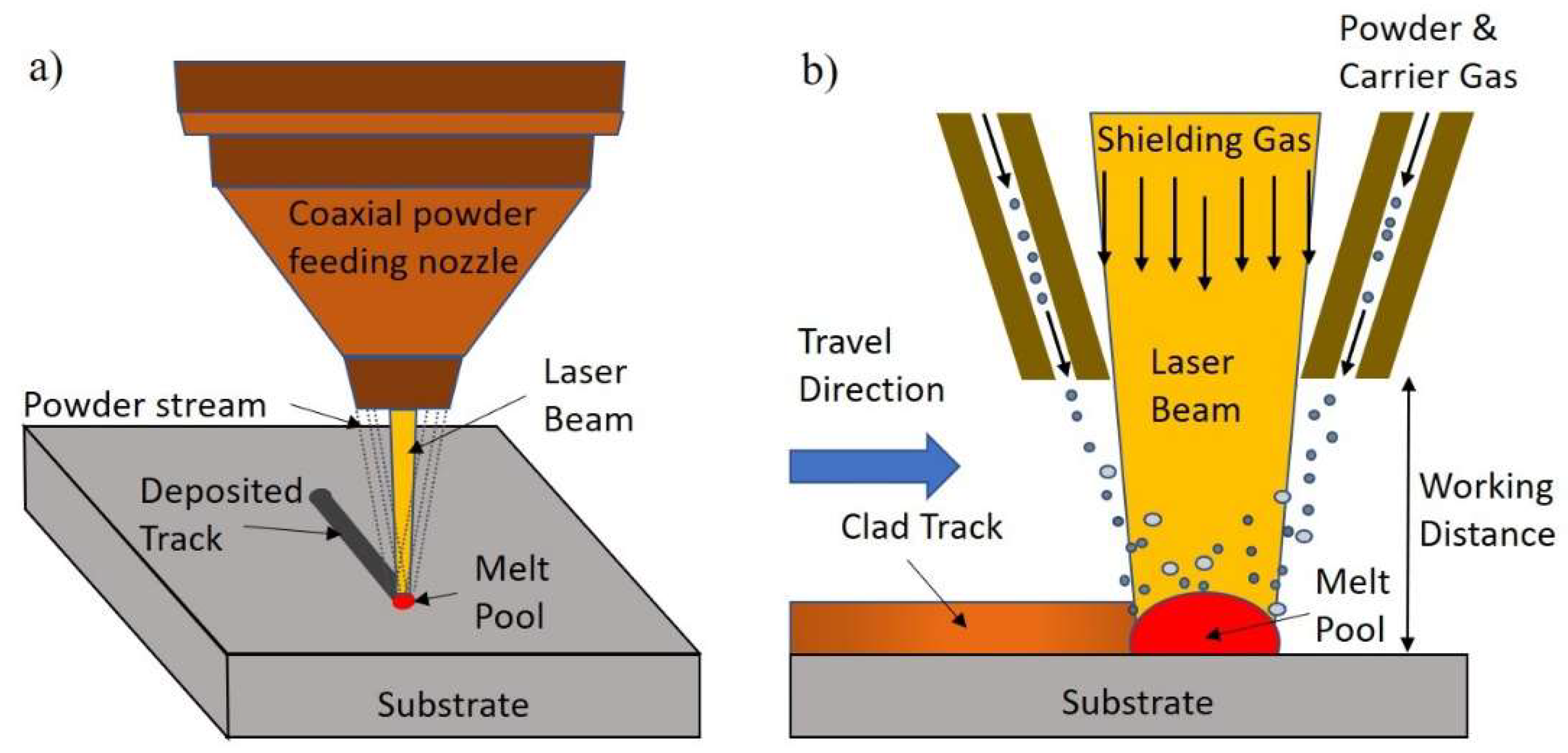
Figure 1 shows the basic principle of directed energy deposition using a laser beam as heat source and powder as feedstock material (DED-LB-p).
Alloy 625 is a face-centred cubic nickel-based superalloy that is strengthened by the solid-hardening effect of refractory metals such as niobium and molybdenum in a nickel-chromium matrix [
8,
9] . The precipitation of the fine metastable phase γ’’(Ni3Nb) after annealing in the temperature range of 550-850 °C is the main reason for the high mechanical properties [
10]. In addition, various carbides such as MC, M6C and M23C6 can also precipitate as a function of time and temperature. The intermetallic Laves- and δ-Phase are also reported [
11].
Recently the field of additive manufacturing has gained a lot of interest and multiple efforts are currently taking to enhance understanding of underlying mechanisms. The application of DED based additive manufacturing in repair was investigated by Saboori et al [
12]. The effect of deposition strategy and post processing on microstructure and mechanical properties of serviced IN625 parts repaired using DED was investigated by Chaurasia et al [
13]. The microstructure and hardness comparison of as- built IN625 alloy following various additive manufacturing processes was reported by Gamon et al [
14].
In this work, samples of Alloy 625 were printed by directed energy deposition (DED-LB-p). The microstructural evolution as well as the mechanical tensile properties at room temperature under varying printing strategies were investigated.
2. Materials and Methods
Gas-atomized powders of Alloy625 were supplied by Inopowders (Germany).
Table 1 shows its chemical compositions. The analysis of the particle size distribution showed that 10 % of the powder measures less than 37.0 µm in diameter, 50 % less than 59.3 µm in diameter, and 90 % less than 93.9 µm [
15].
The flow rate was determined by Hall Flow method to be 16.1 s/50g.
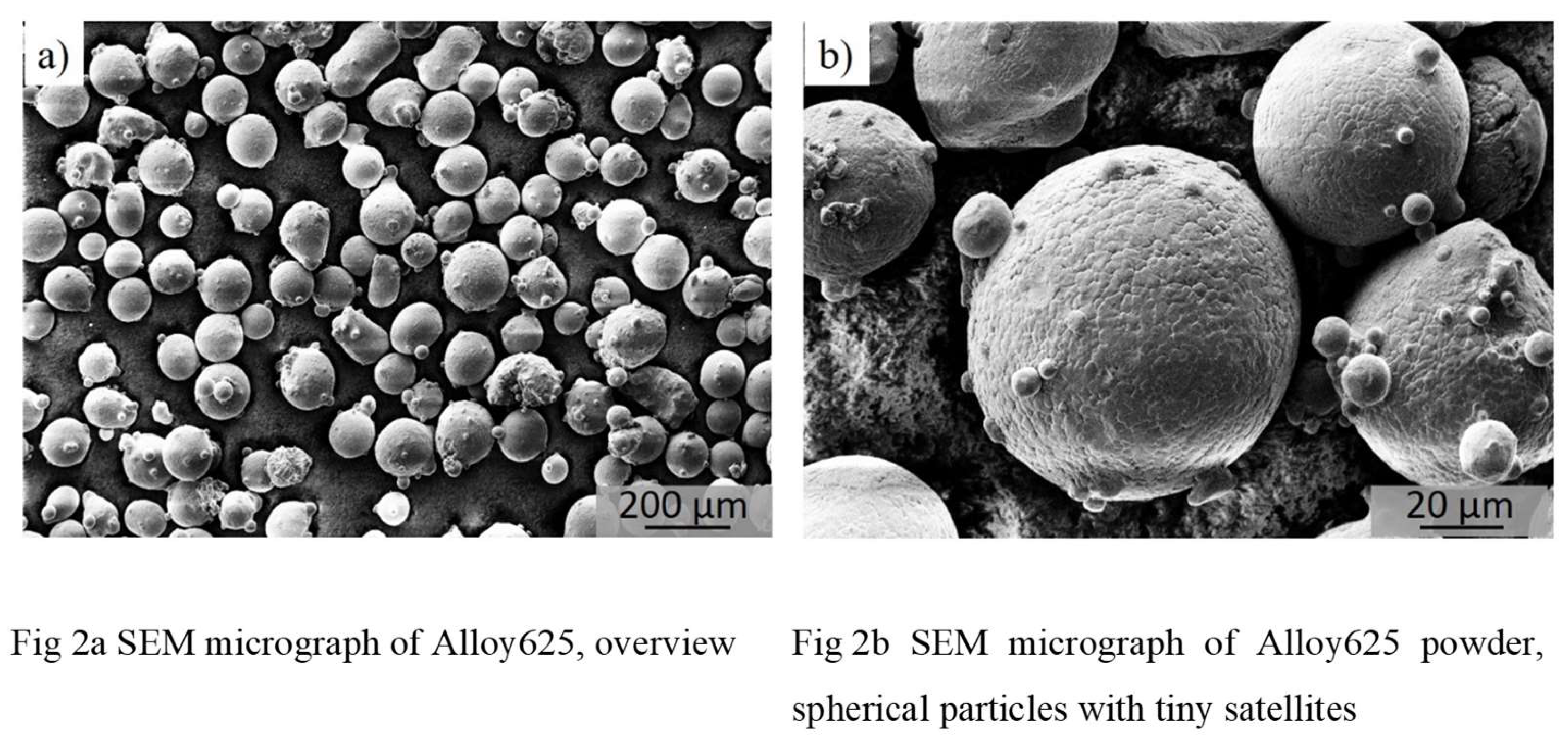
Figure 2a,b present the morphology of the powders used for experiments. The micrographs were obtained using a scanning electron microscope (SEM, Zeis 1540 XB). It can be observed that the majority of the particles have a very spherical shape with small satellites attached to the surface.
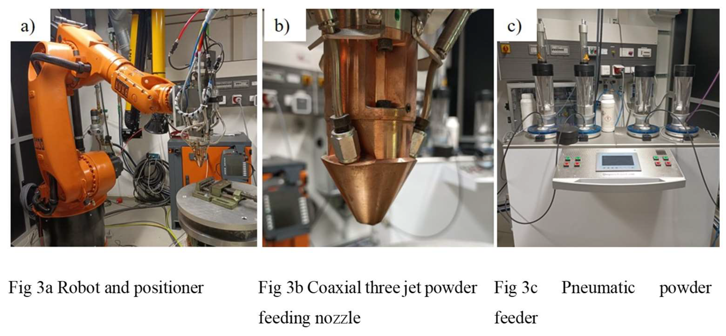
The DED system used for the experiments consists of a disk laser (TruDisk 2000, Trumpf, Ditzingen, Germany) emitting at a wavelength of 1030 nm and a maximum power of 2000 W, a coaxial powder feed nozzle with three nozzles, a six-axis robot (Kuka KR30, Kuka, Augsburg, Germany) and a two-axis positioner (DKP 400, Kuka) on which the substrate is mounted.
Figure 3a-c show the setup used for the experiments.
Sandblasted rolled 304L steel plates with dimensions of 6 x 60 x 100 mm
3 were used as substrate. Prior to deposition the substrates were degreased and cleaned using acetone and ethanol. A pneumatic powder feeder with four independent lines (GTV4, Trumpf, Ditzingen, Germany) was used to transport the powder to the powder nozzle. Argon gas with > 99.999 % purity (with O
2 < 2 ppm, N
2 < 5 ppm, H
2O < 3 ppm and Hydrocarbon < 0.2 ppm) was used as carrier gas and shielding gas for protecting the melt pool from oxidation and subsequent contamination during experiments. The flow rates were experimentally found to be in the range of 5 l min
-1 for carrier gas and 9 l min
-1 for shielding gas. For carrier gas rates less than 5 l min
−1 the powder flow is not stable and reproducible. Carrier gas flow rates higher than 6 l min
-1 result in higher gas velocity, which leads to a loss in efficiency caused by powder ricocheting at the impingement point. These observations are in good accordance with Jinoops [
16] work in which thin walls of Inconel 718 were manufactured by DED.
A number of single tracks were deposited under variation of laser power PL, laser scan speed v and powder feed rate ṁ. The working distance (WD, from end of nozzle to the deposited surface) was generally set at 12 mm, the laser was in-focus. In three following test runs samples were deposited using a laser power of 300, 600 and 700 W, laser scanning speeds in the range of 2 up to 10 mm s-1 and powder feed rates from 3.2 up to 9.1 g min-1. Metallographic cross sections were prepared and examined by light optical microscopy (Zeiss Axioplan 2). The primary goal of these test runs with single tracks was to optimize laser deposition parameters for minimum porosity and maximum deposition rate.
After these trials test runs with four adjacent tracks were conducted. Laser power, scan speed and powder feed rates were identical to deposition of single tracks, overlap Φ of adjacent tracks was 10 to 60 % in 5 % steps. In these tests the influence of the line spacing and thus the overlap on the porosity was analyzed.
The results of the deposition of single and adjacent tracks were used for the deposition of larger volumes in a parameter study in which samples with a geometry of 15 x 15 mm2 and 10 layers were fabricated. Based on the optimized parameter set determined in the preliminary tests samples with varying laser power, scan speed and energy density were deposited.
Energy density was calculated according to equation 1.
With laser power and scan speed.
Table 2 summarizes process parameters used for deposition and resulting porosity values, track height and build rates. Build rates were calculated using equation 2.
With scan speed track width , track height and density .
For the preparation of tensile specimens samples with a geometry of 40 x 25 x 10 mm
3 were fabricated by depositing 20 layers of 25 adjacent tracks each with a length of 40 mm. The process parameters used are those with the lowest porosity in both printing directions (see
Table 2, sample number 2, optimized parameters).
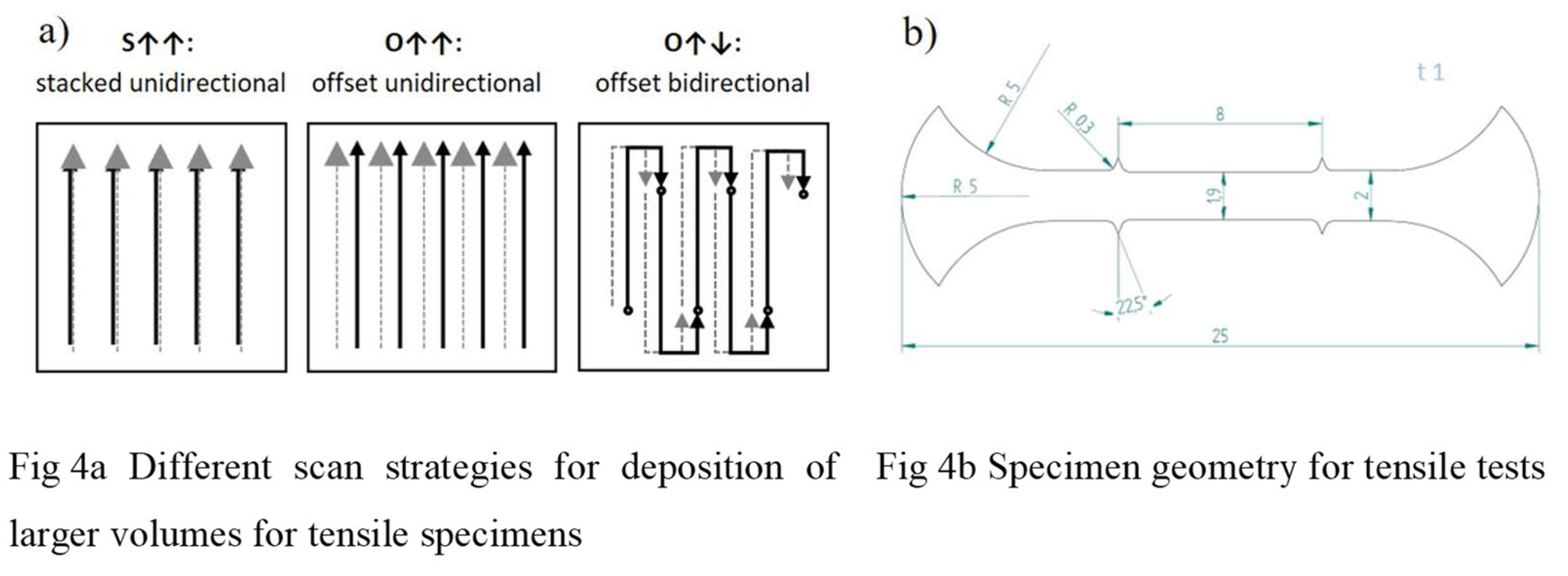
Figure 4a shows the movement of the laser for three different scan strategies which were conducted. In the first case the laser scan direction (SD) for all tracks was identical and the tracks were stacked without any offset from layer to layer (stacked unidirectional). For the second case the laser scan direction was identical within a layer, the offset of the track in the following layer was 50 % of the track width (offset unidirectional). In the third variant the laser scan direction of each track changed by 180° with 50 % offset from layer to layer (offset bidirectional).
Tensile specimens were fabricated using wire electrical discharge machining (AgieCharmilles Cut 200SP). For each build up strategy at least five samples were eroded parallel and perpendicular to the scan direction. The samples used for tensile testing were 25 x 2 x 1 mm
3 in size.
Figure 4b, shows the specimen geometry for tensile tests. Tensile testing was performed using a Zwick Z100 with a strain rate of 0.001 s
-1, the elongation of the specimens was measured with a video extensometer, strain was calculated using Superstrain software as described in [
17].
Scanning electron microscope (SEM; Zeiss 1540 XB) combined with energy dispersive X-ray spectroscopy (EDX) and electron backscatter diffraction (EBSD) was used for microstructural investigation.
3. Results and Discussion
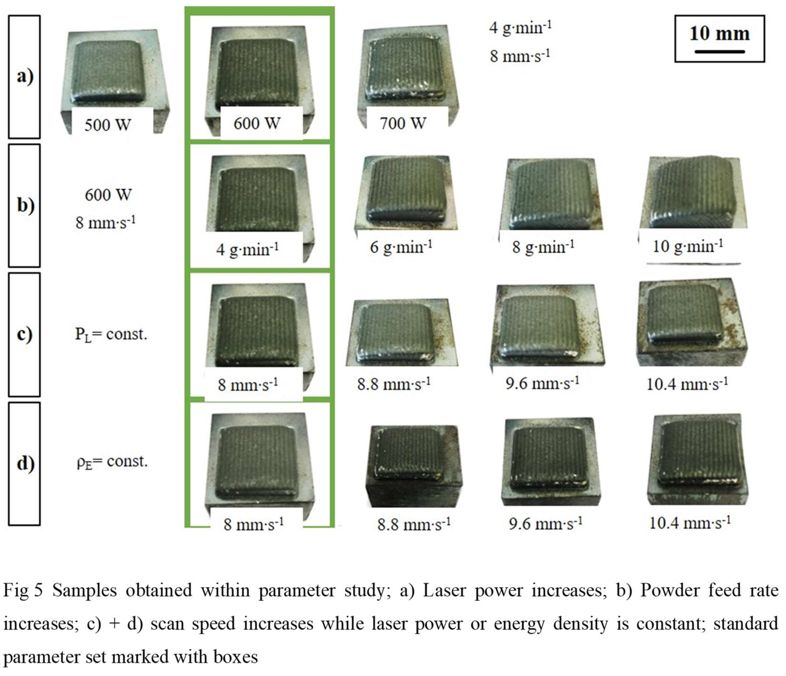
Figure 5 shows the samples obtained in the parameter study in which four different test series were conducted. The standard parameter set is 600 W laser power, 4 g min
-1 powder feed rate and 8 mm s
-1 scan speed. In the first laser power was varied from 500 to 700 W with constant powder feed rate and scan speed (a), in the second powder feed rate was increased by 50, 100 and 150 % with fixed laser power and scan speed (b). In the third test series the laser power was fixed to 600 W while the scan speed was increased by 10, 20 and 30 % (c) and in the fourth test series the scan speed was increased while keeping energy density
constant (d).
The results for porosity are calculated as the mean value and standard deviation from five cross-sections for each orientation. The evaluation is carried out using the bright field of the light microscope perpendicular (ꓕ) and parallel (||) to the scan direction (
Table 2). Apart from sample nr. 6 all printed samples have a low porosity of less than 0.4 %. No trend could be observed here when varying the process parameters. This could be attributed to the high depth of the melt pool in the DED-LB-p process as a reason for the repetitive melting process. However, the process parameters for sample number 2 were selected for further microstructural characterization and mechanical testing. This is because the lowest porosity was achieved with these parameters in both printing directions (perpendicular (ꓕ) and parallel (||)).
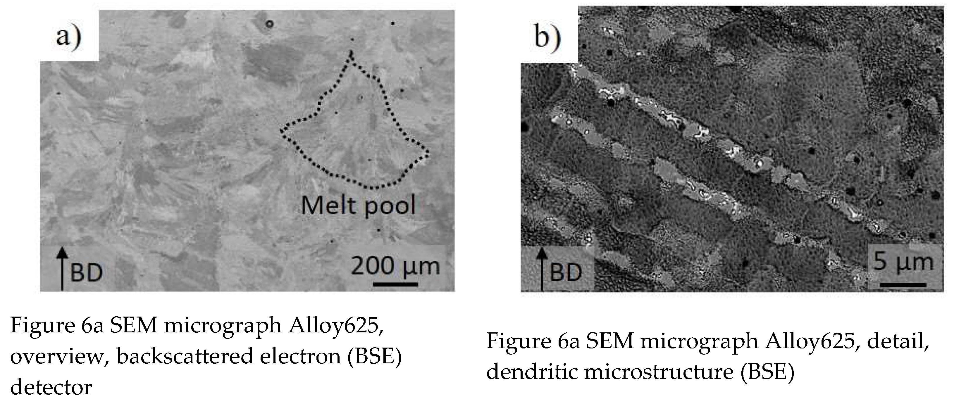
Figure 6a,b show SEM images from cross sections of deposited samples in backscattered mode. The samples were manufactured with the so called “optimized parameters” (denoted Sample 2 in
Table 2). Building direction (BD) was vertical.
Figure 6a shows grains and melt pool tracks of which one is schematically marked with a dotted line.
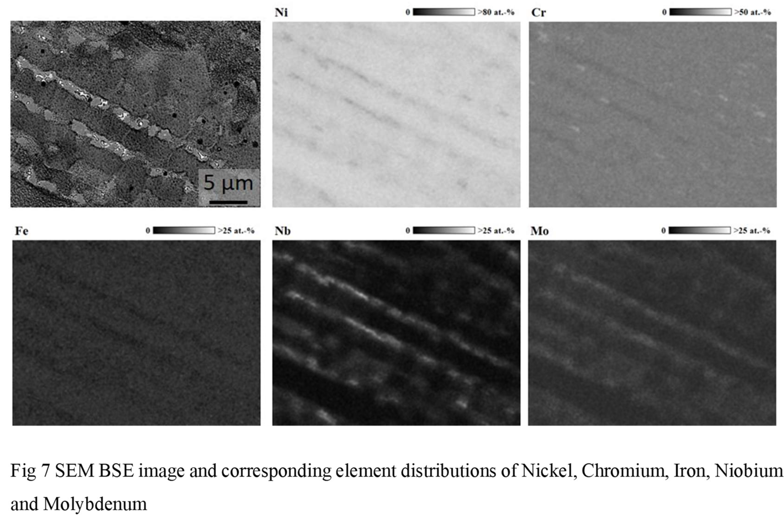
Element mappings show segregation between dendritic and interdendritic regions.
Figure 7 shows a SEM image and the corresponding element distributions in grey scale maps.
The element mappings show that Iron, Chromium and Nickel are located in the dendritic regions whereas Molybdenum and Niobium segregate in the interdendritic regions. The investigation of segregation effects of Niobium in additive manufactured Ni-based superalloys is described in [
18].
Process parameters for depositing larger volumes for tensile tests were 600 W laser power, 8 mm s
-1scan speed and 4 g min
-1 powder feed rate (denoted sample 2, optimized parameter in
Table 2).
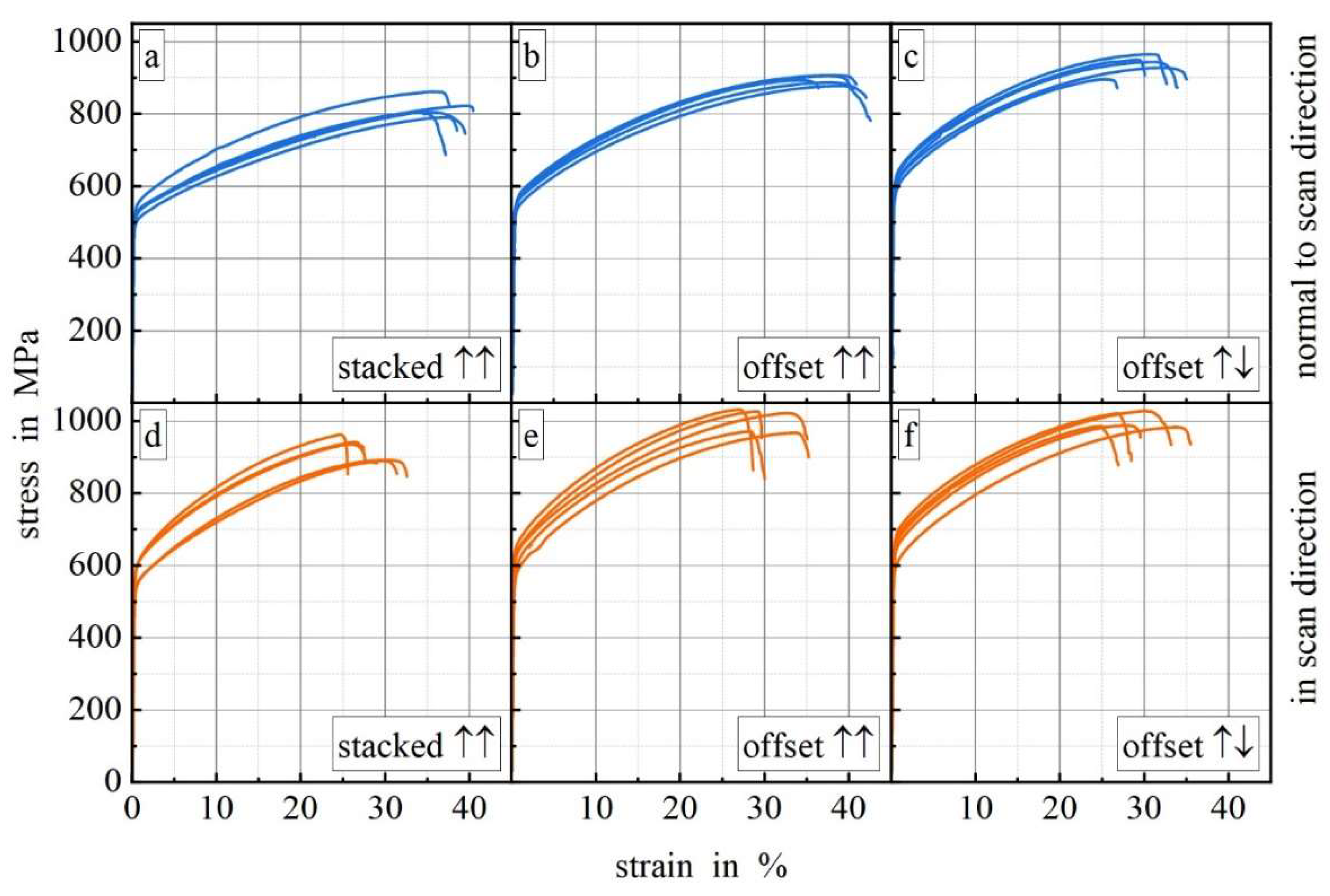
Figure 8 shows stress-strain curves for samples deposited with different scan strategies and the load applied normal to and in scan direction.
All curves exhibit ductile material behavior. For each scan strategy the curves achieve higher strengths in scan direction (8e–f) than normal to scan direction (8a–c). Elongation to failure when load applied normal to scan direction for scan strategies stacked (8a) and offset undirectional (8b) is significantly higher compared to the samples with load applied in build direction. The anisotropy for scan strategy offset bidirectional is lower than for the other strategies.
Table 3 gives an overview of the ultimate tensile strength, yield strength, elongation to failure and porosity for the different scan strategies and compares them with literature.
Ultimate tensile strength and yield strength are for all tested scan strategies in scan direction higher than normal to scan direction. Elongation to failure is for the scanning strategy offset bidirectional in scan direction and normal to scan direction comparable. For the scanning strategies offset and stacked unidirectional elongation to failure normal to scan direction is at least 22 % higher in comparison to in scan direction. In order to get high tensile strength and isotropic deformation the scanning strategy offset bidirectional is recommended.
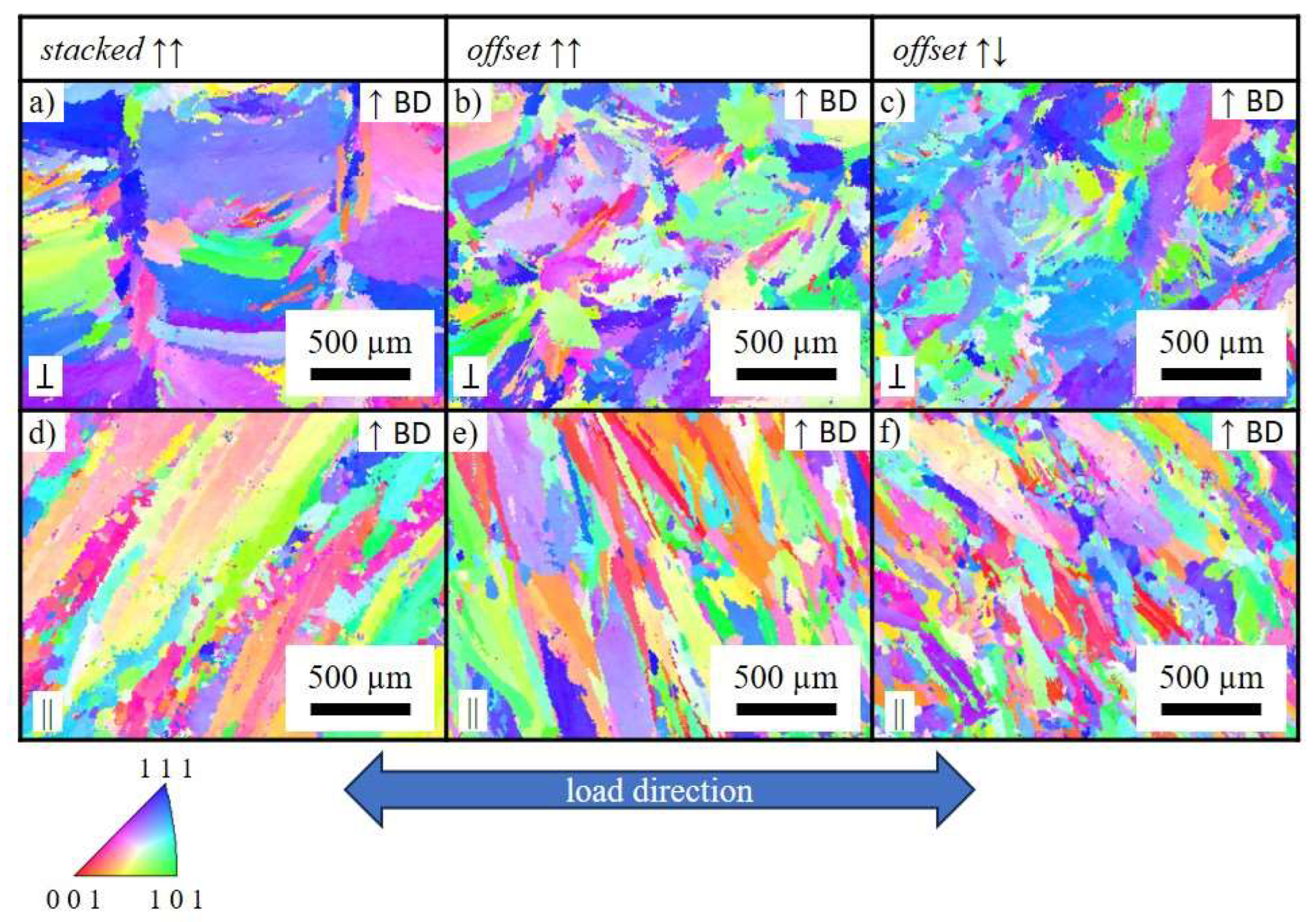
Electron backscattered diffraction (EBSD) analysis was conducted using a Zeiss Sigma 300 SEM, equipped with an EDAX system. Grain size fractions and grain orientations were measured using Orientation Imaging Microscopy (OIM) Software for the three different scan strategies.
Figure 9 shows grain orientation maps for different scan strategies.
Based on grain orientation map data grain sizes in load direction were measured.
Table 4 lists these values.
Depending on the scan strategy the grain size decreases from stacked unidirectional via offset unidirectional to offset bidirectional. The grains in scan direction are smaller than the grains normal to scan direction. The mechanical properties of the samples deposited with offset bidirectional scan strategy show the best mechanical properties which can be attributed to Hall Petch relationship.
The mechanical strength properties of the printed samples with the offset bidirectional scanning strategy are better to those of the wrought alloy (
Table 3). However, the ductility seems to be slightly lower which can be attributed to smaller tensile samples and different cooling rates [
22]. M. Rombouts et al [
19] have obtained the same mechanical properties and process parameters depending on the printing direction and the printing strategies. J. Nguejio [
21] and F. Zafar [
23] attempted to improve the tensile strength of printed samples of Alloy 625 (DED-LB-p) by post-heat treatment and the addition of TiC as reinforcement. A comparable tensile strength of around 1000 MPa was achieved.
Further improvements concerning deposition efficiency of additive manufactured alloy 625 can be realized by using hot-wire laser metal deposition. Su et al [
24] manufactured defect-free thin walled structures with a deposition rate of 1.72 kg h
-1. The UTS of the walls were 826 MPa and therefore only slightly lower.
4. Conclusions
The properties of an Alloy625 alloy obtained by DED were studied, the influence of printing parameters and scanning strategies were considered. The main conclusions of this study are:
Porosities less than 0.5 % for all scanning strategies possible
Deposition volumes of 33 cm3 h-1 (which is 0.28 kg h-1) are deposited
The scan strategy offset bidirectional shows the highest ultimate tensile strength 1001 ± 19 MPa and yield strength 711 ± 27 MPa, the smallest grain size and the lowest anisotropy concerning strength and elongation to failure under different loads
Tensile properties of the printed samples (tensile strength and yield strength) are better than that of wrought parts which is in good accordance with [
25] but their ductility is lower which can be attributed to different sample geometries.
Ultimate tensile strength of 1000 MPa and yield strength over 710 MPa can be realized without any heat treatment.
Author Contributions
All authors have read and agreed to the published version of the manuscript
Funding
The laser system used was partly financed by the german science foundation (DFG) Forschungsgroßgeräte Art 91b GG.
Conflicts of Interest
The authors declare no conflicts of interest.
References
- ISO/ASTM 52900: 2015 additive manufacturing–general principles–terminology, (2792).
- Colomo, A.G.; Wood, D.; Martina, F.; Williams, S.W. A comparison framework to support the selection of the best additive manufacturing process for specific aerospace applications. International Journal of Rapid Manufacturing 2020, 9, 194. [Google Scholar] [CrossRef]
- Yap, C.Y.; Chua, C.K.; Dong, Z.L.; Liu, Z.H.; Zhang, D.Q.; Loh, L.E.; Sing, S.L. Review of selective laser melting: Materials and applications. Applied Physics Reviews 2015, 2, 041101. [Google Scholar] [CrossRef]
- Thompson, M.K.; Moroni, G.; Vaneker, T.; Fadel, G.; Campbell, R.I.; Gibson, I.; Bernard, A.; Schulz, J.; Graf, P.; Ahuja, B.; et al. Design for Additive Manufacturing: Trends, opportunities, considerations, and constraints. CIRP Annals 2016, 65, 737–760. [Google Scholar] [CrossRef]
- Svetlizky, D.; Das, M.; Zheng, B.; Vyatskikh, A.L.; Bose, S.; Bandyopadhyay, A.; Schoenung, J.M.; Lavernia, E.J.; Eliaz, N. Directed energy deposition (DED) additive manufacturing: Physical characteristics, defects, challenges and applications. Materials Today: Proceedings 2021, 49, 271–295. [Google Scholar] [CrossRef]
- ASTM International. ASTM F3187-16: Standard guide for directed energy deposition of metals; ASTM International: West Conshohocken, PA, 2016. [Google Scholar]
- Hilzenthaler, M.; Bifano, L.; Scherm, F.; Fischerauer, G.; Seemann, A.; Glatzel, U. Characterization of recycled AISI 904L superaustenitic steel powder and influence on selective laser melted parts. Powder Technology 2021, 391, 57–68. [Google Scholar] [CrossRef]
- Kumar, P.S.; Elangovan, S.; Mohanraj, R.; Ramakrishna, J.R. A review on properties of Inconel 625 and Inconel 718 fabricated using direct energy deposition. Materials Today: Proceedings 2021, 46, 7892–7906. [Google Scholar]
- Dinda, G.P.; Dasgupta, A.K.; Mazumder, J. Laser aided direct metal deposition of Inconel 625 superalloy: Microstructural evolution and thermal stability. Materials Science and Engineering: A 2009, 509, 98–104. [Google Scholar] [CrossRef]
- Kohl, H.K.; Peng, K. Thermal stability of the superalloys Inconel 625 and Nimonic 86. Journal of Nuclear Materials 1981, 101, 243–250. [Google Scholar] [CrossRef]
- Suave, L.M.; Cormier, J.; Villechaise, P.; Soula, A.; Hervier, Z.; Bertheau, D.; Laigo, J. Microstructural Evolutions During Thermal Aging of Alloy 625: Impact of Temperature and Forming Process. Metallurgical and Materials Transactions A 2014, 45, 2963–2982. [Google Scholar] [CrossRef]
- Saboori, A.; Aversa, A.; Marchese, G.; Biamino, S.; Lombardi, M.; Fino, P. Application of Directed Energy Deposition-Based Additive Manufacturing in Repair. Applied Sciences 2019, 9, 3316. [Google Scholar] [CrossRef]
- Chaurasia, J.K.; Jinoop, A.N.; Paul, C.P.; Bindra, K.S.; Balla, V.K.; Bontha, S. Effect of deposition strategy and post processing on microstructure and mechanical properties of serviced Inconel 625 parts repaired using laser directed energy deposition. Optics & Laser Technology 2024, 168, 109831. [Google Scholar]
- Gamon, A.; Arrieta, E.; Gradl, P.R.; Katsarelis, C.; Murr, L.E.; Wicker, R.B.; Medina, F. Microstructure and hardness comparison of as-built inconel 625 alloy following various additive manufacturing processes. Results in Materials 2021, 12, 100239. [Google Scholar] [CrossRef]
- INOPOWDERS. Material Data Sheet Ni Alloy Type 625 Powder – Batch No 17122501, 2023.
- Jinoop, A.; Paul, C.; Mishra, S.K.; Bindra, K.S. Laser Additive Manufacturing using directed energy deposition of Inconel-718 wall structures with tailored characteristics. Vacuum 2019, 166, 270–278. [Google Scholar] [CrossRef]
- Völkl, R.; Fischer, B.; Beschliesser, M.; Glatzel, U. Evaluating strength at ultra-high temperatures - methods and results. Materials Science and Engineering: A 2008, 483, 587–589. [Google Scholar] [CrossRef]
- Xiao, W.; Xu, Y.; Xiao, H.; Li, S.; Song, L. Investigation of the Nb element segregation for laser additive manufacturing of nickel-based superalloys. International Journal of Heat and Mass Transfer 2021, 180, 121800. [Google Scholar] [CrossRef]
- Rombouts, M.; Maes, G.; Mertens, M.; Hendrix, W. Laser metal deposition of Inconel 625: Microstructure and mechanical properties. Journal of Laser Applications 2012, 24, 052007. [Google Scholar] [CrossRef]
- Chen, F.; Wang, Q.; Zhang, C.; Huang, Z.; Jia, M.; Shen, Q. Microstructures and mechanical behaviors of additive manufactured Inconel 625 alloys via selective laser melting and laser engineered net shaping. Journal of Alloys and Compounds 2022, 917, 165572. [Google Scholar] [CrossRef]
- Nguejio, J.; Szmytka, F.; Hallais, S.; Tanguy, A.; Nardone, S.; Godino Martinez, M. Comparison of microstructure features and mechanical properties for additive manufactured and wrought nickel alloys 625. Materials Science and Engineering: A 2019, 764, 138214. [Google Scholar] [CrossRef]
- Dutkiewicz, J.; Rogal, Ł.; Kalita, D.; Berent, K.; Antoszewski, B.; Danielewski, H.; Węglowski, M.S.; Łazińska, M.; Durejko, T.; Czujko, T. Microstructure and Properties of Inconel 625 Fabricated Using Two Types of Laser Metal Deposition Methods. Materials 2020, 13, 5050. [Google Scholar] [CrossRef]
- Zafar, F.; Emadinia, O.; Conceição, J.; Vieira, M.; Reis, A. A Review on Direct Laser Deposition of Inconel 625 and Inconel 625-Based Composites—Challenges and Prospects. Metals 2023, 13, 787. [Google Scholar] [CrossRef]
- Su, G.; Shi, Y.; Li, G.; Zhang, G.; Xu, Y. Highly-efficient additive manufacturing of Inconel 625 thin wall using hot-wire laser metal deposition: Process optimization, microstructure, and mechanical properties. Optics & Laser Technology 2024, 175, 110763. [Google Scholar]
- Trosch, T.; Strößner, J.; Völkl, R.; Glatzel, U. Microstructure and mechanical properties of selective laser melted Inconel 718 compared to forging and casting. Materials Letters 2016, 164, 428–431. [Google Scholar] [CrossRef]
|
Disclaimer/Publisher’s Note: The statements, opinions and data contained in all publications are solely those of the individual author(s) and contributor(s) and not of MDPI and/or the editor(s). MDPI and/or the editor(s) disclaim responsibility for any injury to people or property resulting from any ideas, methods, instructions or products referred to in the content. |
© 2024 by the authors. Licensee MDPI, Basel, Switzerland. This article is an open access article distributed under the terms and conditions of the Creative Commons Attribution (CC BY) license (http://creativecommons.org/licenses/by/4.0/).
