Preprint
Article

A Comparative Impact Assessment of Hail Damage to Tile and Built-Up Roofing Systems: Technical Review and Field Study

Altmetrics

Downloads

144

Views

94

Comments

0

This version is not peer-reviewed

Submitted:

25 July 2024

Posted:

25 July 2024

You are already at the latest version

Alerts
Abstract
Hail causes damage to property, including roofs, automobiles, and crops, with an average annual loss of $850 million. In residential structures, tile roofing systems are common in the southern U.S. due to their resistance to hail impact and long service life. Additionally, the commercial buildings and some portions of the residential structures have low-sloped or flat roof systems. Commercial low-slope roof systems are equally prone to hail-strike damages as steep residential roof systems. The objectives of this paper are to present a literature review, inspection protocol, and case studies on a comparative assessment of hail threshold for built-up roof (BUR) and tile roof (TR) systems. The published papers determining the hail impact assessment of different roofing systems from 1969 through 2023 were studied and analyzed. This study develops a comparative hail damage assessment table between BUR and TR systems, and the hail threshold for various built-up roof composition systems. In addition, the different failure modes and their causes, the characteristics of hail impacts, and the variables influencing the impact resistance of these roofing systems were examined using field studies. To better understand the effects, it is recommended that an intelligent model be developed to predict the hail resistance threshold of various configurations of BUR and TR systems with critical variables.
Keywords: 
Subject: Engineering  -   Architecture, Building and Construction

1. Introduction and Background

Two types of damaging hailstorms occur in the United States (Greenfeld 1969; CoreLogic 2016). The frontal storm is more prevalent, where hailstones are formed during thunderstorms with strong, sustained updrafts. Initially, the formation of a hailstone begins with a hailstone “kernel” or “nucleus,” which is supercooled water freezing on con
tact with raindrops, dust, etc., to serve as a core for the hailstone’s initial growth (Haag Engineering 2006; Deiling 2020). The newly formed hailstones or frozen particles are lifted and cycled through the lower and upper regions of the thunderstorm with different temperatures, allowing more water to freeze on its surface. This juggling with the hailstone around the freezing level creates concentric layers of clear and white ice around the kernel (Heymsfield 2014).
The milky, opaque layer of ice is formed when water droplets freeze instantly upon impact with the forming hailstone and entraps air bubbles (Morrison 1999; Petty 2013). Similarly, the transparent rings or wet growth forms lower in the cloud with temperatures near freezing levels, and the warmer temperatures let the water droplets freeze slowly,
allowing the air bubbles to escape. The cycle repeats until the hailstone grows too large to be afloat and finally falls to earth, usually at a free-fall terminal velocity (Koontz 1991) (Figure 1). The reported hail densities range between 0.7 to 0.9 g m c m 3 , with the latter value being the density of pure ice (Crenshaw and Koontz 2010; Noon 2001). A typical hailstorm swath contains the largest hailstones in only the central portion of the path, with marble- to pea-sized hailstones toward the outside of the swath (Haag Engineering 2006; RICOWI 2012). The larger hailstones are generally fewer than the small hailstones when present concurrently.
In residential structures, tile roofing systems are common in the southern U.S. due to their resistance to hail impact and long service life. Additionally, the commercial buildings and some portions of the residential structures have low-sloped or flat roof systems. Commercial low-slope roof systems, like built-up roofing (BUR), and steep residential roof systems, like tile roofing (TR) are prone to hail-strike damages (Noon 2001; Petty 2013).
BUR consists of multiple plies or layers of roofing felt bonded together on site with hot bitumen. Since the roof system consists of layers of bitumen and felts, hence the name (built-up). The heart of this roofing system lies in the roofing membrane, composed of bitumen and felts. The bitumen acts as a waterproofing agent and has adhesive properties. It arrives on-site as solid and is applied in one of the following ways. Hot mopping, cold process asphalt, or self-adhesive materials. The bitumen is either a product of petroleum refining – asphalt or a product of coal burning in power plants (Hinojosa and Kane 2001).
The tile roof systems include slate, clay, concrete, fiber cement, and asbestos (Noon 2001; Petty 2013). The tile roof systems are known for their exceptional water-shedding capabilities and ability to withstand continuous age-related weathering. A typical service life of clay roof tiles is at least 70 years or longer (Petty 2013).

1.1. Physics Laws and Basics of Energy Transfer for a Hailstone

According to the law of energy conservation, the total energy associated with a particular system or an object (i.e., hailstone) stays constant over time and thus is neither created nor destroyed (Smith 1975; Petty 2013). The total energy with which a hailstone falls to the ground is the summation of its potential energy, which is the non-moving energy due to height, and the kinetic energy associated with the motion. The total energy of a falling hailstone is given by Equation 1:
E T = E p + E k = Constant
Where:
E T = Total energy of hailstone
E p = potential energy of hailstone
E k = kinetic energy of hailstone
The potential energy of the hailstone while falling is given by Equation 2:
E p = m g h
Where:
m = mass of hailstone
h = height of hailstone above the ground
g = gravitational constant (i.e., 9.8 m/s2, 32.2 feet/s2)
Similarly, the kinetic energy of the hailstone while falling is given by equation 3:
E k = 1 2 m v 2
Where:
m = mass of hailstone
v = velocity of hailstone at any given time
Thus, it should be noted that the potential energy constantly decreases as the height decreases, which means that just prior to the impact with a roof system of a structure, the total energy of the falling hailstone will predominantly be kinetic energy generated due to the decent (Noon 2001; Petty 2013). The acceleration of gravity, g, increases the hailstone’s speed and kinetic energy. However, at some point, it reaches a terminal (constant) velocity when the drag force from the air stops the increase in velocity (i.e., acceleration is zero) (Crenshaw and Koontz 2010; Deiling et al. 2020).
Hail varies by several parameters, amongst which size, shape, density, and terminal velocity are the predominant factors affecting the overall impact or kinetic energy. The terminal velocity of the hailstone, in turn, is influenced by various factors such as drag coefficient, air density, and strong winds (Cullen 1997; Noon 2001; Deiling et al. 2020). In the early 1960s, hail researchers calculated the terminal velocities and corresponding impact energy (Laurie 1967; Greenfeld 1969). More recently, the earlier work was re-evaluated, and a new set of terminal velocity and corresponding impact energy has been found (Heymsfield et al. 2014). The following graph indicates that, for an increase in hailstone diameter from 1.0 inches (2.54 cm) to 3.0 inches (7.62 cm), the impact energy (measured in Joules) for hailstones increases by a factor of 113.6 (Petty 2013).
Amongst the world, the central parts of the United States (U.S.) are where large hail is most frequent (Koontz, 1991). According to a CoreLogic® report, in Texas alone, the residential property damage was estimated to be near $250 million, excluding the vehicle or commercial property after a hailstorm on April 11, 2016 (Morgan 1976; CoreLogic 2016; RICOWI 2016).

2. Objectives and Methodology

The objectives of this paper are to present a literature review, inspection protocol for roof damage assessment, and field studies on a comparative assessment of hail threshold for built-up (BUR) and tile roof (TR) systems. The published papers that directly or indirectly determine the hail impact assessment of different roofing systems from 1969 through 2023 were studied and analyzed. This study develops a comparative hail damage assessment table between BUR and TR systems and the hail threshold for various built-up roof composition systems. In addition, the different failure modes and their causes, the characteristics of hail impacts, and the variables influencing the impact resistance of these roofing systems were examined using field studies. As demonstrated in Figure 2, published papers were collected from various databases, such as ProQuest, Google Scholar, Engineering Village, ASCE Database, Google Scholar, technical bulletins, books, and industry databases, that analyzed hail impact on BUR and TR systems from 1969 through 2023. All of these papers were reviewed, and essential data—the year of study, BUR system types, TR system types, hail thresholds, ASTM standards used, dependent and independent variables, and variables influencing impact resistance—were collected.

3. Roofing Systems

3.1. Built-Up Roof Systems

By definition, a low-sloped roof system consists of roof categories that are installed on slopes that are 3:12 or less (Petty 2013; Dodson 2023). Majorly, the commercial buildings and some portions of the residential structures have low-sloped or flat roof systems. The cost of removing and replacing commercial low-sloped roof systems is ten times greater ($100,000 vs. $10,000) than the replacement cost of a steep-sloped roof system (Petty 2013). Different types of finished surfaces for a low-sloped roof system include asphaltic bitumen built up in layers (BUR), bitumen modified with polymers (mod-bit), and single-ply synthetic materials.
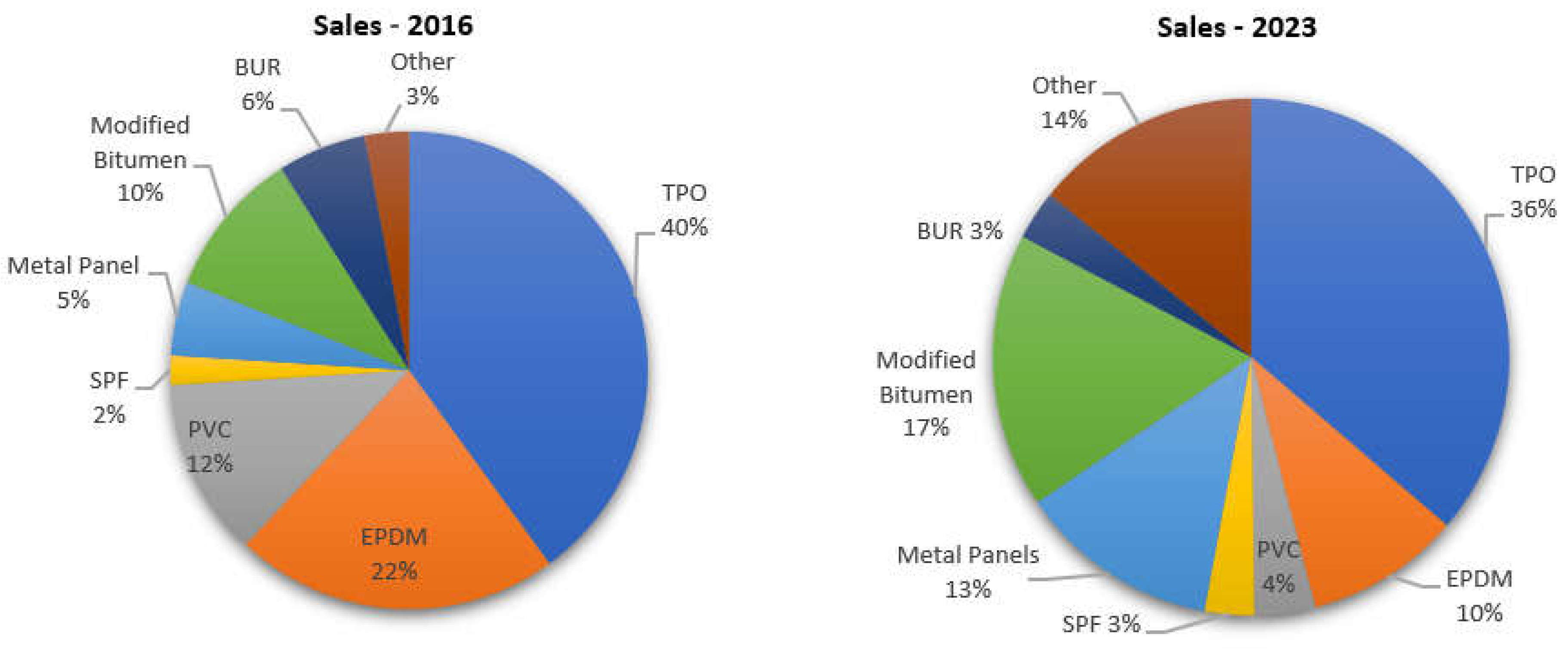
The low-sloped roofing market accounted for about 63% of the total roofing market in 2001 (Hinojosa and Kane 2001). The market decreased to 55% in 2023, which still dominates over half of the total roofing market (Dodson 2023) (Figure 3).
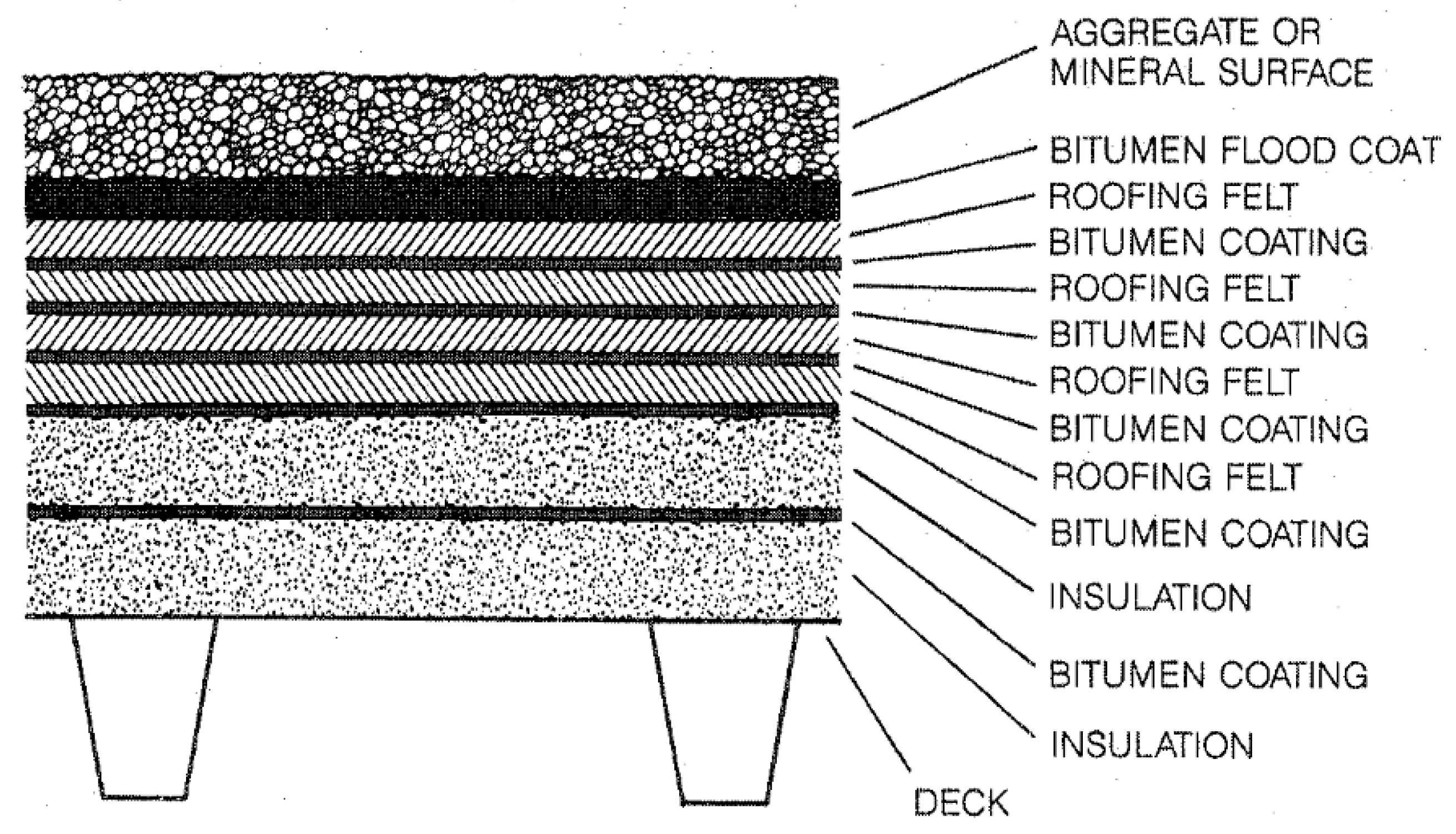
Built-up roofs have been around since 1844 and have dominated the marketplace for several years (Petty 2013). A built-up roof system comprises a roof deck, vapor retarder, insulation, membrane, and surfacing material (Figure 4).
Most felts used in current BUR systems are manufactured with a fiberglass-reinforced mat, though older felts can contain organic mats. Fiberglass felts are the latest in the roofing industry since they are more moisture resistant than organic felts, which are moisture resistant only in areas saturated with bitumen. The fiberglass mats are coated with bitumen at the plant, creating a strong bond with the felt. Built-up roofs commonly surface with gravel embedded in the top layer of hot bitumen to protect from damaging ultraviolet radiation and mechanical damage from hail and foot traffic. Another common surface coating is a granule-surfaced cap sheet or smooth surface, referred to as modified bituminous roofing. Above this, aluminum or zinc coating increases reflectivity and provides UV protection to the roof surface (Figure 5).
BUR is laid down to conform to the roofing substrate and to seal all angles formed by projecting surfaces to create a single-unit waterproof membrane. The waterproofing properties of BUR depend on the existence of continuous bitumen films. The felt stabilizes and prevents rupture or flow of the bituminous films and generally strengthens the roof covering. The simple principle for BUR is to turn the membrane up to make a skirting or base flashing on vertical surfaces, forming a large watertight tray. The roof drainage system is the only outlet from this tray to remove water.
American Society for Testing and Materials (ASTM) D-312 provides standards for selecting the proper bitumen. Bitumen is classified into four types (Table 1). The asphalt/bitumen is susceptible to damage from overheating. A drop in softening point can crack or degrade the asphalt. As the softening point decreases, the “holding power” of the asphalt decreases, resulting in slippage (Synder 1984). If the overheating is gradual, the asphalt “ages” prematurely, losing the beneficial oils that help the asphalt to stay waterproof and unweathered. Depending on the type of bitumen allows the owner to choose the kind of slope the roof will have (Trumbull 1997).
Type-I is “relatively susceptible” to flow at roof temperatures and is used from “dead level” to slopes not above ½-inch per foot (Fricklas 1989). It’s common in the industry to limit Type I to ¼ inch, especially when used with glass fiber ply felts. It’s a preferred “flood coat” or “top pour” on flat roofs, as it serves as a self-healing binder for the roofing gravel. Type II is “moderately susceptible to flow and used as a compromise on glass fiber roofs to slopes of ½ inch or higher. Type III has become very popular in the industry due to its high melt-point, and it can be safely used on roof decks and joints without the concern of “drippage” into the structure. However, since the bitumen has low tensile strength, it cannot withstand normal building stresses independently.
Hence, roofing felt, plies, or reinforcement fabric must be added to stabilize and strengthen the roofing membrane. Apart from strengthening the membrane, the roofing felt also resists puncturing and tearing of the roof, eliminates bitumen flow, increases resilience and pliability of the roofing membrane, protects bitumen from water degradation, and serves as fire-retarding elements in the membrane system.
Service Life: The roofing industry traditionally has assigned five years of anticipated service life to each felt ply; hence, a 25-year service life could be expected on a five-ply BUR (D’ Annunzio 2004). The mean service life of an asphaltic fiberglass reinforced membrane is between 15-20 years (D’Annunzio 2004; Hoff J 2007).

3.2. Tile Roofing System (TR)

A common type of roofing system used for residential structures is the tile roofing system. Different types of common concrete and clay tiles include (Concrete Tile Roofing 2024):
Barrel Tiles: These are also known as S-tiles due to their semi-cylindrical shape. These tiles are heavy and are the most expensive design options. In clay barrel tiles, the wave pattern is formed by alternating concave dips with convex covers forming half-moon-shaped barrels.
  • Flat Tiles: These are the most common concrete roofing tiles. For the clay flat tiles, the durability of terracotta clay.
  • French Tiles: These tiles have deep locks on all four sides, plus two prominent flutes on the surface. French clay tiles are a low-profile option with two protruding flues per tile.
  • Double Roman Tiles: The Double Roman is a standard profiled concrete roof. These Tiles have a small round roll and are also known as mission tiles.
  • Spanish Tiles: These tiles provide a pattern of distinctive ripples across the roof and are popular in heavy rain regions. These have an S-shaped design similar to mission tiles. These can be clay or concrete.
  • Scalloped Tiles: These concrete tiles have a curved bottom edge, which gives them a fish-scale appearance.

3.3. Inspection Protocol for Roof Damage Assessment

The study of roofs begins by studying the collateral indicators, which provide tangible and clear clues about the direction of hailstorms, the density of hailstones, the diameter of the hailstones, and much more. The following is the summary of the inspection protocol (Figure 6). The collateral indicators include, but are not limited to, exterior metal appurtenances, exterior wood surfaces, windows, window screens, and heating, ventilating, and air conditioning (HVAC) condenser fins. On the roof, the metal roof appurtenances such as box vents, powered attic vents, plumbing stack flashing, chimney caps, soft-metal flue caps, and the flashings at the wall-slope interfaces and valley provide collateral evidence (Mayercsik and Bennett 2022).
The inspection methodology for a tile roof system is unique and different from other roofing systems. The scope of the investigation or inspection for hail projects is typically clear: to determine whether the tile roofing system is damaged by hail. Further, the total number of tiles covering the roof slopes will be estimated from the area measurements of the roof and the tiles (width and exposure). The amount of functional hail-strike damage to all the roof slopes is reported as a percentage of the roof surface area for each elevation inspected.
If tiles are loose and can be removed without damage, the manufacturer’s information, size, and type of tile can be noted. Any evidence of fractures, punctures, or chips associated with hail impact or windborne debris will be documented. The fracture in the tile may provide evidence of the relative age of the break (Marshall et al. 2002). For instance, bright-colored cracked edges or rounded edges filled with debris. The fractures also include the right or left corner fractures, which must be studied for the general frequency and location throughout the roof slopes. The investigator should observe if corner breaks occur in relatively shaded areas like under trees.
Horizontal or vertical cracks in tile are typically not related to hail. Hail causes a radial-type fracture pattern. Horizontal and vertical cracks are typically from install/handling or from foot traffic. It should be noted whether the cracked pieces are still in place, near the parent tile, or are missing. For instance, fragments are often close to the originating tile if the hailstorm was recent. Any previous repairs, including different colored sealants, adhesive sheets, or other repair material if used, should also be considered if the damaged tiles are grouped closely along the travel paths, like a valley, which is unlikely to be the result of hail, since hailstones should fall at random and not be localized in an area. Roof sketches are a good tool for annotating and indicating the location of the damage.

4. Comparative Impact Assessment and Discussion

A technical literature review is conducted using various academic and industry databases on the hail impact damages to BUR and TR systems. According to Greenfeld’s report, a number of non-bituminous roofing products were tested to determine the threshold of hail damage. Greenfeld reported the smallest hailstone size causing damage to red clay tile was 2 inches for the center and 1 ¾ inches for the unsupported edge of the tile (Greenfeld et al.1969). This study did not investigate concrete tiles.
According to Koontz et al. (1991), three concrete tile targets all exhibited fairly high degrees of hail resistance. Fracture/breakage occurred when the velocity was increased to 131 feet per second (40 meters per second) or 89 mph, resulting in kinetic energy of 71.49 feet per second. The flatter concrete tile shingle was the most hail-resistant concrete tile product tested. Multiple impacts with 2%-inch (64-mm) hail were required before fracture/breakage occurred. Concrete tile systems appear to offer a very high degree of hail resistance. The lower-profile shingle— either flat or lower configurations—results in increased hail resistance.
According to Marshall et al. (2004), none of the concrete tiles tested were fractured by 1 in. diameter ice balls, even in their most sensitive locations. Four of the 13 tiles were fractured at their corners with ice balls as small as 1.25 in. in diameter. Six of the 13 tiles remained unbroken when impacted with 1.50 in. diameter ice balls. Ice balls 2.5 inches in diameter broke all tiles. These test results correlated well with their observations of concrete tile roofs after actual hailstorms.
A threshold is the smallest size of hail at which the damage can occur. Based on testing and field experience, if a hard hailstone strikes perpendicular to a clay tile, the threshold size for the damage is 1 ½ inches in diameter. Similarly, for a concrete tile, the threshold size for damage is 1 ¾ inches in diameter (Haag Engineering 2006). Damage to roofing can be categorized as cosmetic or functional damage (Marshall and Herzog 1999; Marshall et al. 2004; Morrison 2009). In the insurance and roofing market, a standard definition for functional damage to the roofing system is a structure is defined as follows: (1) reduction or diminution of its water-shedding or weather resistance capabilities and (2) reduction in the expected long-term service life of a roofing material. On the other hand, cosmetic damage affects only the appearance or aesthetic appeal of the roof and does not fall under the category of functional damage (Cullen 1997).
For causing functional damage to a roofing tile system, the hailstone should have a minimum size to generate sufficient impact energy. Oftentimes, when hailstones are not of sufficient size to cause functional damage to tile roofing systems, burnish marks to the tile exposures will be observed, with no associated penetrations, fractures, splits, chips, or impressions will be present. This is not functional damage and will not likely shorten the expected service life of the tiles (Mayercsik and Bennett 2022).
“The smallest size where the hailstone can cause damage to a given material is known as the threshold size of hail for that material” (Haag 2006; Petty 2013). The hailstone size threshold for functional damage to any roofing material is defined as “The minimum or smallest size of natural hail at which functional damage typically begins to occur and refers to hailstones that strike perpendicular to the surface of the roofing material, which is in relatively good, mid-life conditions” (Morrison 1999; Shephard and Gromicko 2006).

4.1. Hail Threshold

BUR System
The threshold hail diameter needed to cause damage to the BUR roofing materials is summarized in Table 2.
TR System
The functional damage to roof tile caused by a hail impact must have one or all of the following conditions (Greenfeld 1969; Cullen 1997; Marshall and Herzog 1999; Marshall et al. 2004; Petty 2013):
  • A radiating fracture or multiple irregular fractures radiating out from the point of impact.
  • Complete shatter, penetration, or puncture through the tile.
  • Cracks or breaks in the tile’s exposure or fractures above the head lap are functional damage as they inhibit the tiles’ ability to shed water.
  • Crescent-shaped breaks along the thinner edges or corners of S-shaped tiles, particularly where they interface with adjacent tiles.
  • Chips at the tile’s corners with the evidence of burnish mark.
  • Substrate damage or discernable impressions left that broke through the surface layers.
Experience has shown that some types are more prone to hail damage than others. For example, lightweight concrete and relatively thin tiles are more prone to hail damage than their heavier, thicker counterparts. The threshold hail diameter needed to cause damage to the concrete and clay tile roofing materials is summarized in Table 3.
The comparative assessment of BUR and TR systems is tabulated in Table 4.

4.2. Failure Modes

BUR System
Defects in BUR membranes are associated with installation anomaly, normal aging, and exposure to elements (Petty 2013). The common defects in BUR are tabulated in Table 5.
Blistering. Blisters are spongy, dome-shaped areas caused by gases (air or water vapor) that expand beneath or within roof membrane plies (Korhonen and Charest 1995). It can also result from moisture trapped within a roof assembly, expanding to vapor (1400 x expansion). The blisters form from voids built into the roof, either between the plies or between the bottom of the membrane and impermeable substrate (Korhonen and Bayer 1986; Korhonen 1989; Korhonen and Charest 1995). Voids can form from too-cold asphalt when poured so that it does not adhere to the felt, skips in the bitumen mopping, entrapped debris, bitumen bubbling, walking on freshly laid plies, or curled felt edges. Blistering of the built-up roofing takes two main forms: blistering between the roof membrane and substrate and blistering between the membrane plies.
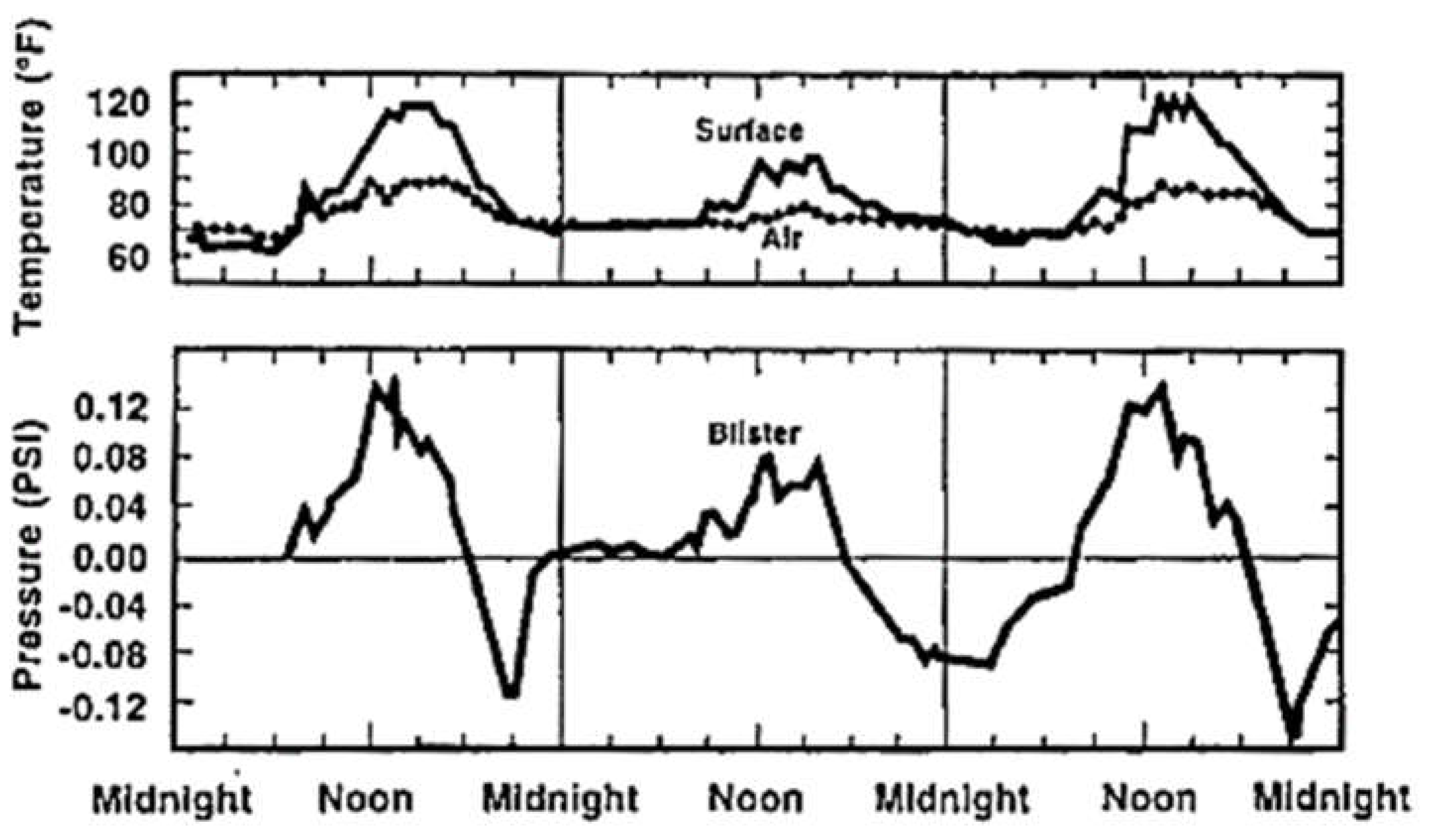
A blister grows within a void from the expansion of gases under the sun’s intense heat. However, the mere expansion is not the sole reason for the large blisters (Cullen 1993). A small void that grows into a characteristic bloated hump several inches high to a few feet across is a breathing action called thermal cycling. The pressure changes within the membrane voids cause the blister growth (Figure 7). A blister cycles between positive to negative pressures daily and typically goes from overpressure during the day to under pressure at night. This also indicates that blisters are not air-tight, but leak air through the microscopic cracks in the bitumen and microporous felts (Korhonen and Bayer 1986; Korhonen 1989).
It shortens the membrane life by decreasing its vulnerability to physical damage and weathering. The sloped sides of the blister will cause the aggregate to roll downhill and expose the flood coat and felt to increased embrittlement by ultraviolet rays. Puncturing the blisters by foot traffic or inadvertent man-made damage allows water/moisture to access the roof system directly.
Splitting/Ridging/ Wrinkles. A long and narrow blister is a ridge (Melnick 1989). It resulted from the movement of the roof assembly, loss of the physical properties of the membrane as it ages, low fatigue resistance, and acceleration by vapor drive (Barrett 2000). Other causes include wrinkled felt, moisture through the substrate or insulation, blockage in holes of asphalt, curling edges of insulation and slipping of felt plies, structural movement, cracking of substrate, differential movement of different decks, lack of attachment to the substrate, shrinkage in concrete deck, lack of expansion joints in the roof membrane. The fiberglass felt has limited elongation properties and no recovery characteristics. Due to the ultraviolet aging and water, it loses its minor elongation properties. After aging and associated loss in physical properties, the movement induced by daily and seasonal thermal cycling results in splitting and ridging of the membrane and, ultimately, fatigue failure. About 12% of the roofs were reported to have these problems in 1988 (Melnick 1989). It’s pertinent to differentiate between blistering and ridging since these two distresses have different leak potentials. The severity levels of blisters are: (1) Low: The raised areas are noticeable by vision or feel, but the surfacing is still in place and felts are not exposed; (2) Medium: The felts are exposed and show deterioration, and (3) High: The blisters are broken. At high severity levels, distinguishing between ridging and blistering is very important.
Deterioration from Ponding Water. The most probable cause of the ponding water is improper design with inadequate slopes for drainage (Petty 2013). A sufficient slope must be provided to ensure proper drainage and avoid standing water ponds. Section R905 of the International Residential Code (IRC) and Section 1507 of the International Building Code (IBC) state that the minimum slope of BUR is ¼ inch per foot. However, coal tar built-up roofs can have a minimum slope of ⅛ inch per foot. This code requirement is for new roofs, and that existing roofs may have been designed under previous codes.
Bare Spots from loss of gravel. An area where the gravel is missing, the coating is lost, or the felt deteriorated. The probable causes of bare spots include inadequate bonding of aggregate/gravel with the bitumen at the edges, corners, and through the field, gravels applied in adverse weather conditions, too thin or too fine gravel at the edges and corners, wind scour, erosion due to water flow, coating over dirty or poorly prepared felts, and traffic on the roof.
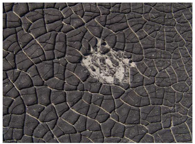
Alligator Cracking. Cracking in the membrane surface resembles alligator skin or dried mud. These occur on smooth surfaces or bare spots with missing gravel. The causes of this are the heaviness of the flood coat of asphalt or the loss of volatiles in the flood coat due to UV exposure or aging.
Fish mouthing. An open lap or separation in the roofing membrane is caused by improper installation, un-ironed wrinkles in the membrane, and installing felts with damp edges.
Flashing Failures. These occur due to punctures, tears, and wrinkling from the movement between the parapet and deck or other structural movements, differential movement between metal flashings, gravel stops, scuppers, etc., improperly securing the membranes at the top of flashings or on walls, no or inadequate allowance for movement, corroded metal, damage to the capping at the parapets and expansion joints.
TR System
Corner Fractures. Corner fractures or chips along the tile edges can be mistakenly identified as hail damage. However, a close examination usually reveals algae or dirt with weathered edges or caulking, indicating these have been historically present. A major cause of right corner fractures is shunting the tiles together with no room for expansion. The tiles expand typically due to thermal expansion/contraction and moisture. Hence, they need room to expand. With no room, the resulting strains fracture the thinner overlap region of the tile, which is the lower right corner (looking upslope). Hence, tiles with interlocking side joints should be installed with maximum “play” in order to accommodate lateral movement (Marshall et al. 2004; Petty 2013).
The corner fractures do not result in water infiltration, provided the crack remains below the head lap region. An installed tile’s required overlap portion (head lap region) is usually 3 inches. The secondary fractures extending above the head lap region are less common and qualify for replacement (TRI 2010). The other causes that promote right corner fractures include shrinkage cracks, which form as the tile dries unevenly, and a small nub that extends from the lower left corner on the adjacent tile.
Inadvertent Human-Made Damage to Tile Roofs. Due to the brittle nature of the tiles, any activity by workers can damage the tiles. A person walking improperly on a tile can break the tiles across their widths. Typically, stepping at the bottom three inches of the installed tile is recommended, where the underlying lugs provide firm support, and the weight is transferred through it to the deck below (TRI 2014). The center of the tile has little to no underlying support and, hence, is easier to break underfoot. The major footfall is common in high-traffic areas like valleys, and therefore, it is recommended to stay away from hips or valleys to avoid breaking cut tiles that would be more difficult to replace.
Voids in Tile. Often, irregular pop-outs on the surface of a concrete tile could be mistakenly marked as hail damage. These open voids in the face of tile sporadically on several tiles are casting defects due to the air pockets in the concrete (Petty et al. 2009).

4.3. Case Studies on TR and BUR Systems

Normal-weight concrete roof tiles stamped with “Monier-Monray” on the underside were installed on the house built in 1980 in Denton County, Texas. The tiles are installed with nominal 1-inch by 4-inch (1x4) battens at 12-inch spacing with no roof underlayment beneath the battens. The roof has a slope of 4:12. Based on the study of the on-site collateral indicators included oblong dents in the downspouts, tears in the window screens, chips in the weathered wood fence, dents in the cooling fins, dents in the roof appurtenances, cracked skylight indicate that hail up to 2 inches in diameter fell at this site.
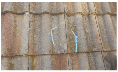
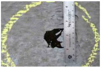
A total of 12 field tiles have larger fractures extending along the tile exposure, punctures, chipped with crescent-shaped cracks, and a point of fracture with radiating cracks. These have associated spatter marks up to 1 ½ inches and expose a bright-colored concrete edge. Approximately 85 tiles have fractured or chipped lower-right corner edges of the tiles throughout the roof on each elevation. The edges of the exposed tile are weathered, algae-covered, covered with adhesive sheets, or have caulking. Linear cracks or fractures along the length of the tile are commonly seen on the roof. The cracks are localized near the likely travel path, valleys, or near the roof penetrations. A few tiles have these open voids sporadically in the face of tile on several elevations. Table 6 depicts the typical functional hail-strike and non-strike damage for the roofs in consideration.
Built-up roofs with smooth and gravel surfacing were included in the study. The first two case studies included commercial building roofs with a smooth surface BUR for building 1 and a reflective coating as the top flood coat for building 2. The inspection of the metal surfaces indicated that the hail that struck the building and the roof surfaces was up to 2 ½ inches for building 1 and 2 ¼ inches for building 2. The top finished surface indicated circular indentations and penetrations consistent with hail impact. The hail stones caused damage to the entire top, and cracks or penetrations were present in the membrane when the test cuts were made.

5. Contribution to the Body of Knowledge and Conclusions

This paper presented a thorough technical review, inspection protocol for roof damage assessment, authors’ experience, and case studies on a comparative assessment of hail threshold for BUR and TR systems. This study developed a comparative hail damage assessment table between BUR and TR systems and the hail threshold for various built-up roof composition systems. In addition, the different failure modes and their causes, the characteristics of hail impacts, and the variables influencing the impact resistance of these roofing systems were examined using field studies. A methodology was presented with the help of field studies to determine whether the hail event damaged the TR and BUR systems. It can be concluded that the house’s tile roof covering was damaged by hail impacts, with approximately 0.15% of the total roof area. The field tiles with larger fractures, punctures, splits, and crescent-shaped cracks have spatter marks and bright-colored concrete edges exposed, indicating the tiles were recently impacted by hail. The corner cracks tiles, most of the detached pieces near the parent tile, and expose algae-covered edges, indicating historical damage due to thermal contraction and expansion of the tiles. Numerous other defects were found on the roof, including inadvertent man-made damage, corner fractures, and open voids. A procedure of monitoring service life and future repairs by homeowners of the studied roof coverings would provide data on the long-term effects of hail impact on the tile roofing system.

6. Recommendations for Future Research

In the future, there is a need to describe the effect of winds on the terminal velocity of the hail and the corresponding impact on the tile roofing system. More field campaigns should be conducted to measure hailstones on-site or shortly after falling. More data can be collected by investigating a greater variety of roofing systems, and statistically critical roofs in a certain hail-prone area could be considered, which could further help us understand the performance of TR and BUR systems. To better understand the effect of hail impact on different compositions of BUR and TR systems, it is recommended that an intelligent model be developed to predict the hail resistance threshold of various configurations of BUR and TR systems with more critical input variables.

Notation

The following symbols are used in this paper:
E T Total energy of hailstone
E k kinetic energy of hailstone
E p potential energy of hailstone
AI Artificial Intelligence
BUR Built-up roofing system
C surface Cracked
D Foamboard Delaminated
F Felts Cracked
g gravitational constant (i.e., 9.8 m/s2, 32.2 feet/s2)
h height of hailstone above the ground
HVAC Heating, ventilation, and air conditioning (HVAC)
m mass of hailstone
N No visible indentation
P Penetrated Roofing
ND No Damage
NRCA National Roofing Contractor Association
NT Not Tested
S Surface Shattered
THR Threshold for Damage
TR Tile roofing system
UTA University of Texas at Arlington
v velocity of hailstone at any given time

Author Contributions

Conceptualization, Vinayak Kaushal and Mohammad Najafi; Methodology, Gayatri Thakre, Vinayak Kaushal and Mohammad Najafi; Investigation, Gayatri Thakre; Data curation, Gayatri Thakre; Writing – original draft, Gayatri Thakre; Writing – review & editing, Vinayak Kaushal and Mohammad Najafi; Visualization, Mohammad Najafi; Supervision, Vinayak Kaushal.

Data Availability Statement

No data, models, or codes were generated or used during the study.

References

  1. CoreLogic. “Everything is Bigger in Texas-Hail Events 2016.” Accessed February 6, 2024 http://www.corelogic.com/about-us/researchtrends/everything-is-biggerin-texas-hail-events-2016.aspx#.
  2. Crenshaw, V., and J. D. Koontz. 2010. “Hail: Sizing it Up!”. Accessed February 10, 2024, http://www.hailtrax. com/hail_size_it_up.pdf.
  3. Cullen, W. C. 1997. “Hail damage to roofing: Assessment and classification.” In Proc., Fourth International Symposium on Roofing Technology, NRCA/NIST, Gaithersburg, Maryland, 211–216.
  4. Deiling, C., M. Smith, and M. Beruvides. 2020. “ Review of Impact Factors of the Velocity of Large Hailstones for Laboratory Hail Impact Testing Consideration.” Geosciences 2020.
  5. Dodson M. 2023. “Low Slope Roofing Market.” Accessed March 17, 2024. Western Roofing Market. https://www.westernroofing.net/2023/11/22/low-slope-roofing-market/.
  6. Fricklas, R. L. 1989. “Judging The Performance of Roofing Asphalt.” The Better Understanding Of Roofing Systems Institute (BURSI).
  7. Greenfeld, S. H. 1969. “Hail Resistance of Roofing Products.” National Bureau of Standards Inst. For Applied Technology: Washington D.C. (U.S.), Building Science Series #23, 1-11.
  8. Griffith, M. , and J. A. Morgan. 1976. “On the Role of Strong Winds in Damage to Crops by Hail and its Estimation with a Simple Instrument.” Journal Of Applied Meteorology Vol 15, 891-898.
  9. Haag Engineering. 2006. “Hailstorm Characteristics”. Accessed February 9, 2024. http://www.haagengineering.com/ehail/chas/ eHail/hailstorm.html.
  10. Heymsfield, A. J., I. M., Giammanco, and R. Wright. 2014. “Terminal velocities and kinetic energies of natural hailstones.” Geophysical research letters, American Geophysical Union. 8666–8672.
  11. Hill V. 2017. “Roofing Trends”. Accessed March 18, 2024, International Institute of Building Enclosures Consultants. https://iibec.org/wp-content/uploads/2017-03-hill.pdf.
  12. Hinojosa O., K. Kane. 2002. “A measure of the industry.” Accessed March 17, 2024. NRCA Professional Roofing. https://www.professionalroofing.net/Articles/A-measure-of-the-industry--04-01-2002/41.
  13. Koontz, J.D. 1991. “What are the Effects of Hail on Residential Roofing Products.” In Proc., Third International Symposium on Roofing Technology, 206-215.
  14. Laurie, J. A. P. 1960. “Hail and Its Effects on Buildings,” Research Report 176, NBRI, Pretoria, South Africa, 1960.
  15. Marshall, T. P. , and R. F. Herzog. 2002. “Protocol for Assessment of Hail-Damaged Roofing.” In Proc., Proceedings of the North American Conference on Roofing Technology. 40-46.
  16. Marshall, T. P., R. F. Herzog, S. J. Morrison, and S. R. Smith. 2002. “Hail Damage Threshold Sizes for Common Roofing Materials.” Dallas, TX: Haag Engineering Co.
  17. Marshall, T. P., R. F. Herzog, S. J. Morrison, and S. R. Smith. 2004. “Hail damage to tile roofing.” In Proc., 22nd Conference on Severe Local Storms.
  18. Mayercsik, N.P. , and P. J. Bennett. 2022. “Assessing Hail Damage to Concrete Tile Shingles: An Analytical Method and a Case Study.” In Proc., Ninth Congress on Forensic Engineering, Denver, Colorado. Sponsored by the Forensic Engineering Division of ASCE.
  19. Morrison, S. J. 1999. “Long-Term Effects of Hail Impact on Asphalt Shingles – An Interim Report.” In Proc., Proceedings of the North American Conference on Roofing Technology.
  20. Morrison, S. J. 2009. “Holy Hail.” National Roofing Contractors Association. Accessed February 7, 2024, https://www.professionalroofing.net/Articles/Holy-hail--06-01-2009/1506.
  21. NOAA NSSL (National Oceanic and Atmospheric Administration) (National Severe Storms Laboratory). “Hail Basics.” Accessed February 6, 2024. https://www.nssl.noaa.gov/education/svrwx101/hail/#:~:text=Hailstones%20are%20formed%20when%20raindrops,freeze%20onto%20the%20hailstone’s%20surface.
  22. Noon, R. K. 2001. Forensic Engineering Investigation. Boca Raton, FL: CRC Press.
  23. Petty, S. E. 2013. Forensic Engineering Damage Assessments for Residential and Commercial Structures. Boca Raton, FL: CRC Press, 103-115.
  24. Petty, S.E., M. A Petty., and T. Kasberg. 2009. “Evaluation of Hail-Strike Damage to Asphalt Shingles Based on Hailstone Size, Roof Pitch, Direction of Incoming Storm, and Facing Roof Direction.” Interface Magazine, 4–10.
  25. Rajeev, P., J. G. Sanjayan, and S. S. Seenuth. 2016. “Assessment of thermal cracking in concrete roof tiles.” Materials and Design 107. 470–477.
  26. RICOWI (The Roofing Industry Committee on Weather Issues, Inc.). 2004. Hailstorm Investigation Report Oklahoma City, OK, April 21, 2004.
  27. RICOWI (The Roofing Industry Committee on Weather Issues, Inc.). 2012. Hailstorm Investigation Report Dallas/Fort Worth, TX May 24, 2011.
  28. RICOWI (The Roofing Industry Committee on Weather Issues, Inc.). 2016. Hailstorm Investigation Report North Texas, TX April 11, 2016.
  29. Shephard K., N. Gromicko. 2006. “Mastering Roof Inspections: Hail Damage, Part 6.” International Association of Certified Home Inspectors®. Accessed February 9, 2024, https://www.nachi.org/hail-damage-part6-33.htm.
  30. Smith J. M., H. C. Van Ness. 1975. Introduction to Chemical Engineering Thermodynamics, 3rd ed. New York: McGraw-Hill Book Company.
  31. TRI (Tile Roof Institute). 1999. “Technical Brief: Chipped Tile.” Technical Brief. Accessed February 9, 2024. https://tileroofing.org/wp-content/uploads/19TRI036_99-002-chipped-tile_d2.pdf.
  32. TRI (Tile Roof Institute). 2010. “Hail Damage is Not indicative of a Manufacturing Defect.” Technical Brief. Accessed February 9, 2024. https://tileroofing.org/wp-content/uploads/19TRI036_2010-001-hail-damage_d2.pdf.
  33. TRI (Tile Roof Institute). 2014. “Concrete Roof Tiles.” Technical Brief. Accessed February 9, 2024. https://tileroofing.org/wp-content/uploads/19TRI036_PCATechBrief-concrete-homes_d2.pdf.
  34. TRI (Tile Roof Institute). 2014. “Technical Brief: Walkability on Concrete and Clay Roof Tiles.” Technical Brief. Accessed February 9, 2024. https://tileroofing.org/wp-content/uploads/19TRI036_Technical-Brief-2014-02-Walkability_d2.pdf.
  35. Verhulst, S. M. 2018. “Hail Sizing: A Comparison of On-Site Data with Weather Data”. In Proc., Forensic Engineering 8th Congress: Forging Forensic Frontiers. Austin, Texas. Sponsored by the Forensic Engineering Division of ASCE.
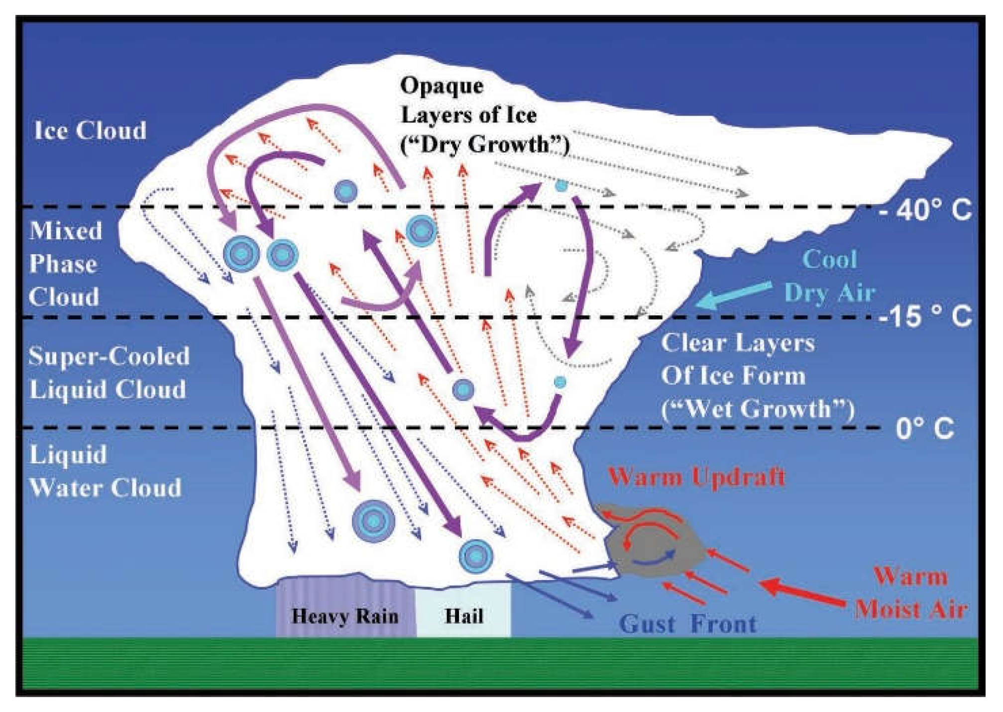
Figure 1. Hailstone Formation within Thunderstorm Cloud. Source: Petty 2013.
Preprints 113246 g001
Figure 2. Research Methodology.
Preprints 113246 g002
Figure 3. Sales Comparison of Product Mix of Low-Sloped in 2016 and 2023. Source: National Roofing Contractor Association 2023.
Preprints 113246 g003
Figure 4. Built-up Roof (BUR) Composition. Source: Roofing Series- Built-Up Systems (1984).
Preprints 113246 g004
Figure 5. BUR Composition Summary.
Preprints 113246 g005
Figure 6. Inspection Protocol for Roof Damage Assessment.
Preprints 113246 g006
Figure 7. Top Graph – Air and Blister Surface Temperature. Bottom Graph – Pressure Difference between Inside of Blister and Atmosphere. Source: Bailey D, Roofer: A management tool for maintaining built-up roofs (1999).
Preprints 113246 g007
Table 1. ASTM D-312 Classification.
Product Types of Bitumen Roof Grade Softening PointMin. Max.
140°F (60°C) Type I Dead Level 135°F (57°C) 151 °F (66°C)
170°F (77°C) Type II Flat Grade 158°F (70°C) 176 °F (80°C)
190°F (88°C) Type III Steep Grade 185°F (85°C) 205 °F (96°C)
220°F (104°C) Type IV Special Steep 210°F (99°C) 225 °F (107°C)
Table 2. Hail Resistance of BURs (Modified from Greenfeld 1969).
Hail Damage Indentation Size (mean diameter of indentation)
Hailstone Size, in(cm) 1 ½ (3.8) 1 ¾ (4.5) 2(5.1) 2 ½ (6.4)
1. Base sheet plus organic felt, asphalt flood coat on
a. ½ inch (1.3 cm) plywood 5/8 (1.6) 5/8 (1.6) 5/8 (1.6) C 1 ¼ (1.6) C
b. 1-inch (2.5 cm) fiberboard on ½ inch (1.3 cm) plywood 5/8 (1.6) 1 (2.5) C 1 ¼ (3.2) C 1 5/8 (4.1) C
c. 1-inch (2.5 cm) Foamboard A on ½ inch (1.3 cm) plywood 5/8 (1.6) NT 5/8 (1.6) 2 ¼ (5.7) P
d. 1-inch (2.5 cm) Foamboard B on ½ inch (1.3 cm) plywood ¾ (1.9) NT 1 ¼ (3.2) D NT
e. 1-inch (2.5 cm) Asbestos Cement 7/8 (2.2) NT 1 (2.5) C 1 ¼ (3.2) C
f. 1-inch (2.5 cm) Fiberboard on 22 Ga. Steel Decking ¾ (1.9) 7/8 (2.2) 1 ¼ (3.2) C 1 ¾ (4.5) C
g. 1-inch (2.5 cm) Glass fiber insulation on 22 Ga. Steel Deck N 1 (2.5) C 1 ¼ (3.2) C 2 ¼ (5.7) FP
2. Base sheet plus asbestos felt, asphalt flood coat on
a. ½ inch (1.3 cm) plywood N NT N N
b. 1-inch (2.5 cm) Asbestos Cement N N 1 (2.5) N
c. 1-inch (2.5 cm) fiberboard on ½ inch (1.3 cm) plywood N N 1 (2.5) C NT
3. Base sheet plus tarred felt, tar flood coat on
a. ½ inch (1.3 cm) plywood C ½ (1.3) C C CS
b. 1-inch (2.5 cm) Asbestos Cement C NT N C
c. 1-inch (2.5 cm) fiberboard on ½ inch (1.3 cm) plywood C NT C 2 (5) C
4. 2 Glass felt + 1 glass cap sheet on
a. ½ inch (1.3 cm) plywood N NT ½ (1.3) 1 (2.5)
b. 1-inch (2.5 cm) Asbestos Cement N NT N N
c. 1-inch (2.5 cm) fiberboard on ½ inch (1.3 cm) plywood ¾ (1.9) NT 1 (2.5) 1 ½ (3.8) C
d. 1-inch (2.5 cm) fiberboard on 1-inch (2.5 cm) Asbestos Cement ½ (1.3) NT N 1 ½ (3.8) C
e. ¾-inch (1.9 cm) Glass fiber insulation on 1/2-inch (1.3 cm) plywood 5/8 (1.6) NT 1 1/8 (2.8) 1 ¾ (4.5) C
f. ¾-inch (1.9 cm) Glass fiber insulation on 1-inch (2.5 cm) Asbestos Cement ½ (1.3) NT 7/8 (2.2) 1 ½ (3.8) C
5. 2 Base sheets, asphalt flood coat on
a. ½ inch (1.3 cm) plywood ½ (1.3) C NT 7/8 (2.2) C 1 ¼ (3.2) C
b. 1-inch (2.5 cm) Asbestos Cement N NT N N
c. 1-inch (2.5 cm) fiberboard on ½ inch (1.3 cm) plywood ¾ (1.9) C ¾ (1.9) C 1 1/8 (2.8) C NT
d. 1-inch (2.5 cm) fiberboard on 1-inch (2.5 cm) Asbestos Cement 5/8 (1.6) C 7/8 (2.2) C 1 (2.5) C NT
6. 2 Base sheets, asphalt flood coat + slag on
a. ½ inch (1.3 cm) plywood N NT N N
b. 1-inch (2.5 cm) Asbestos Cement N NT N N
c. 1-inch (2.5 cm) fiberboard on ½ inch (1.3 cm) plywood N NT N N
d. 1-inch (2.5 cm) fiberboard on 1-inch (2.5 cm) asbestos cement N NT N N
Note: C – Surface Cracked; D – Foamboard Delaminated; F – Felts Cracked; N – No visible indentation; P – Penetrated Roofing; S – Surface Shattered; NT – Not Tested.
Table 3. Threshold Hail Size for Concrete and Clay Tile Roofing.
References Hail Size (Inches) Damage Classification
Marshall et al. (2004)
Concrete Tile 1.0 ND
1.25 4 of the 13 tiles had corners damaged
1.5 7 of 13 tiles are damaged
2.5 all the tiles are broken
Clay S-Tile 1.0 ND
1.25 ND
1.5 All tile corners broke
Marshall et al. (2004a)
Flat Concrete Tile 1.25 20 percent (%) tiles are damaged
1.5 50 % of tiles are damaged
1.75 50 % of tiles are damaged
2 100 % of tiles are damaged
S-Shaped Conc. Tile 1-1.75 ND
2.0 80% of tiles are damaged
Koontz J.D. (1991)
Concrete Tile 2.5 Fractures with multiple impacts
Haag (2006)
Clay 1.5 THR
Concrete Tile 1.75 THR
Greenfeld (1969)
Red Clay Tile 1.5-1.75 Unsupported edges
2 Center
Note: N.D. - No Damage; THR - Threshold for Damage.
Table 4. Comparative Assessment of Hail Impact on BUR and TR Systems.
Hail Diameter
Literature
Hail Threshold for Roofing Configuration Systems (inches)
Built-up Concrete and Clay Tile
1 1 ¼ 1 ½ 1 5/8 1 ¾ 2 2 ¼ 2 ½ 1 1 ¼ 1 ½ 1 5/8 1 ¾ 2 2 ¼ 2 ½
Greenfeld (1969)
Mathey and Cullen (1974)
Haag (1988)
Koontz (1991)
Haag (1993)
Cullen (1997)
Crenshaw and Koontz (2000)
Noon (2002)
Marshall and Morrison (2004)
Marshall et al. (2004)
Marshall et al. (2004a)
Haag (2006)
RICOWI (2011)
Petty (2013)
Herzog, RICOWI (2016)
Table 5. Built-up Roofing Distress.
Flashing Membrane
Base Flashing Blisters
Metal Cap Flashing Ridges
Flashed Penetrations Splits
Alligator Cracking
Surface Deterioration
Bare Spots on Gravel
Ponding
Fish mouths
Slippage
Table 6. Typical Damage to Roofing Systems.
Defects Image
Hail-strike types of failures
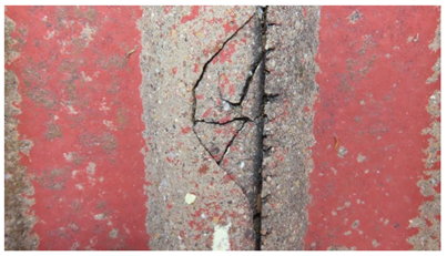
A crescent-shaped crack in concrete field tile with a central impact point Preprints 113246 i001
A crescent-shaped crack in concrete field tile with associated spatter mark Preprints 113246 i002
A finish displacement in the top coat of the BUR system Preprints 113246 i003
Circular cracks in BUR membrane with associated dull interiors exposed Preprints 113246 i004
Disclaimer/Publisher’s Note: The statements, opinions and data contained in all publications are solely those of the individual author(s) and contributor(s) and not of MDPI and/or the editor(s). MDPI and/or the editor(s) disclaim responsibility for any injury to people or property resulting from any ideas, methods, instructions or products referred to in the content.
Copyright: This open access article is published under a Creative Commons CC BY 4.0 license, which permit the free download, distribution, and reuse, provided that the author and preprint are cited in any reuse.
Prerpints.org logo

Preprints.org is a free preprint server supported by MDPI in Basel, Switzerland.

Subscribe

© 2024 MDPI (Basel, Switzerland) unless otherwise stated