1. Introduction
The permanent storage of carbon dioxide (CO
2) is vital in virtually all mitigation scenarios compatible with ambitious climate targets. CO
2 storage could be used, both for the CO
2 captured from the flue gas of industrial processes and for the CO
2 sequestrated from the atmosphere through artificial processes.[
1]
The most developed approach for storing CO
2 is the geological storage, namely the injection of CO
2 in geological formations, e.g. in deep saline aquifers.[
2] Because the pace and scaling of geological CO
2 storage deployment have fallen short of expectations, and considering that this approach is unfeasible in many geographical areas, [
3,
4,
5] there is an increasing interest in alternative solutions that could provide permanent storage of large quantities of CO
2.
Many authors have proposed and studied the storage of carbon dioxide in seawater, which already contains 98% of the overall CO
2 in the combined ocean-atmosphere system.[
6] The large majority of this (86.5%) is actually in the form of bicarbonate ions (HCO
3-).[
6] Marine storage of CO
2 in the form of bicarbonate ions has the potential to last for geologic times, on the order of 10,000 years.[
7,
8,
9] Rau and Caldeira [
10,
11] proposed a method called Accelerated Weathering of Limestone (AWL), consisting of the reaction of CO
2 from power plants exhaust gas with seawater and calcium carbonate minerals (CaCO
3), namely calcite or aragonite, with a final discharge in the ocean of an ionic solution rich in bicarbonates. The overall “weathering” reaction may be summarized as follows:
This method has progressed from the laboratory level[
12] to the feasibility case study[
13] and to a pilot-scale reactor,[
14] as well as with modelling of local impacts on seawater carbonate chemistry. [
15] An improvement of this method, named buffered accelerated weathering of limestone (BAWL), has been proposed by Caserini et al.[
16] With this approach, CO
2 is used in stoichiometric excess with respect to the carbonate minerals, but calcium hydroxide [Ca(OH)
2, also known as slaked lime, SL] is added in the final stages of the process to produce a buffered ionic solution at the same pH of the seawater. De Marco et al.[
17] investigated mass and energy balances and the costs of applying BAWL to the capture and storage of CO
2 from the flue gas of an existing industrial source, and concluded that the process is technically feasible and economically viable.
One intrinsic shortcoming of the AWL and BAWL is the slow rate of the reaction between aqueous CO
2 and limestone. As a consequence, big plants treating large amounts of seawater would be necessary for marine storage of CO
2. The Limenet
® [
18] process is an evolution of BAWL that attempts to overcome this problem by the direct combination of CO
2 with Ca(OH)
2, to induce the overall reaction:
The reaction is carried out in specially designed reactors, where CO
2 is first dissolved in seawater, and then Ca(OH)
2 is added to give a bicarbonate-enriched solution with a pH equal to that of natural seawater. As an additional benefit, the solution has a large alkalinity, thus increasing the buffer capacity of seawater against acidification.[
19] For this reason, those technologies are classified as Ocean Alkalinity Enhancement (OAE) processes. The SL employed in reaction (2) is typically produced by calcination of limestone, an energy-intensive process, that produces one mol of CO
2 per mol of CaCO
3. Any additional CO
2 emission can be avoided by using renewable energies for the calcination and by sequestering the CO
2 with one half of the produced Ca(OH)
2. Therefore, ideally this process enables the net sequestration of one mol of CO
2 per mol of CaCO
3.
The fundamental question which inspired this research is whether the increased amount of bicarbonate in seawater remains stable over time and therefore fulfils the requirements for permanent storage. The aim is also to identify the optimal relative amounts of seawater, CO
2 and Ca(OH)
2 that avoid CO
2 degassing as well as abiotic or biotic precipitation of carbonate minerals. These are two of the strongest pitfalls of such approaches, because carbonate precipitation would lead to the re-emission of CO
2 in the atmosphere, by a reaction that is essentially the reverse of (1):
These questions were prompted, amongst other things, by analogous studies of the stability of seawater treated by ocean liming (OL) operations.[
7,
20,
21] OL consists in the direct dispersion of Ca(OH)
2 on the surface of seawater, to induce an additional absorption of atmospheric CO
2.[
7] Those studies demonstrated that, apart from causing potentially harmful spikes of the seawater pH, such OAE operations may also be ineffective because they trigger unwanted side reactions like (3). While the classical ocean liming is an unequilibrated process, the injection of a bicarbonate solution has the inherent advantage of leaving the seawater pH unaltered. In fact, the dissolution of calcium hydroxide occurs in a closed system and with the exact amount of water needed. Only afterwards, the bicarbonate-enriched marine solution is released into the sea, at the same pH. This pH-equilibrated marine solution implies fewer serendipities and unpredictable behaviours than ocean liming, especially pH pikes and possible precipitation of carbonates.
In this respect it is important to stress that ocean surface is heavily supersaturated in carbonate minerals, which implies a high risk of precipitation. A sudden and uncontrolled increase of the local concentration of carbonate ions may trigger the nucleation and therefore the precipitation of the carbonate minerals. In particular, the aragonite saturation state:
(where [
X] is the molar concentration and
KSP is the stoichiometric solubility product of aragonite in seawater) ranges between 2.7 and 3.7 in the Mediterranean Sea.[
22] The aragonite saturation state is considered a useful indicator of the risk of precipitation, even though it is more soluble than calcite, because precipitation of the latter is inhibited by the high concentration of magnesium in seawater.
Having this in mind, we have tested the stability of seawater solutions containing an enhanced concentration of bicarbonate ions, in two distinct sets of experiments:
- (a)
natural seawater treated with the Limenet® process at a site located in the harbour of La Spezia (Italy), and subsequently transferred to our laboratory at the Politecnico di Milano for long-term monitoring;
- (b)
artificial seawater prepared and treated in the laboratory with controlled additions of sodium bicarbonate.
Furthermore, we have evaluated the durability of CO2 stored in the form of dissolved bicarbonates through measurements of the pH, Dissolved Inorganic Carbon (DIC) and Total Alkalinity (TA).
Within the scope of our study, it is important to stress that DIC approximately coincides with the sum of C contained in HCO3- and CO32- because the smaller contribution of CO2 can be ignored in seawater and no other inorganic C is present. On the other hand, TA is approximately the sum of quantities of HCO3- and 2 times CO32-. Both indicators are therefore useful to monitor the C content in seawater. Our observations have been correlated with the calculated saturation states (Ω) of calcite and aragonite [equation (4)]. We have monitored these parameters over long time periods, ranging from a few days up to three months. This allowed us to assess the stability of the treated solutions.
2. Results
Table 1 summarizes the series of experiments that we carried out to test the stability of bicarbonate-enriched seawater solutions. The first column contains labels used throughout the manuscript to indicate a series of samples and experimental conditions. These can be classified according to the following variables (see Materials and Methods for more details):
- 1)
Mode: carbon was added to the solutions either in a single step or by multiple additions over a period of several days.
- 2)
Seawater: we used either natural seawater (collected from the Mediterranean Sea at La Spezia) or artificial seawater (prepared from purified water and inorganic salts).
- 3)
Environment: we measured the evolution of the treated solutions either in an open atmosphere or otherwise in closed cabinets with a fixed volume of enclosed air (ca. 300 L). We call “mixed” the experiments where we have temporarily opened the cabinet to perform the addition of sodium bicarbonate.
- 4)
Treatment: the alkalinization of seawater was obtained either with a concentrated solution of sodium bicarbonate or through the Limenet® process. The latter implies the formation of calcium bicarbonate from the neutralization of carbon dioxide and calcium hydroxide, as described in the Introduction and in Materials and Methods. These treatments are indicated in the table as NaHCO3 and Ca(HCO3)2, respectively.
- 5)
MaxΔDIC: the largest theoretical amount of added carbon (in µmol/L), for a series of experiments. It is a theoretical value because it represents the expected increase of the DIC, assuming an ideal addition without degassing or precipitation.
- 6)
Initial DIC: in the experiments with natural seawater, the measured initial DIC was 2370 µmol/L for SN1/SN2 and 2470 µmol/L for MN. In the experiments with artificial seawater (MA and SA), the initial DIC was set to 2000 µmol/L[
23] or to 2800 µmol/L obtained from the dissolution of NaHCO
3.
- 7)
Duration: it refers to the longest duration of a set of experiments. Measurements were carried out in the laboratory for up to 90 days.
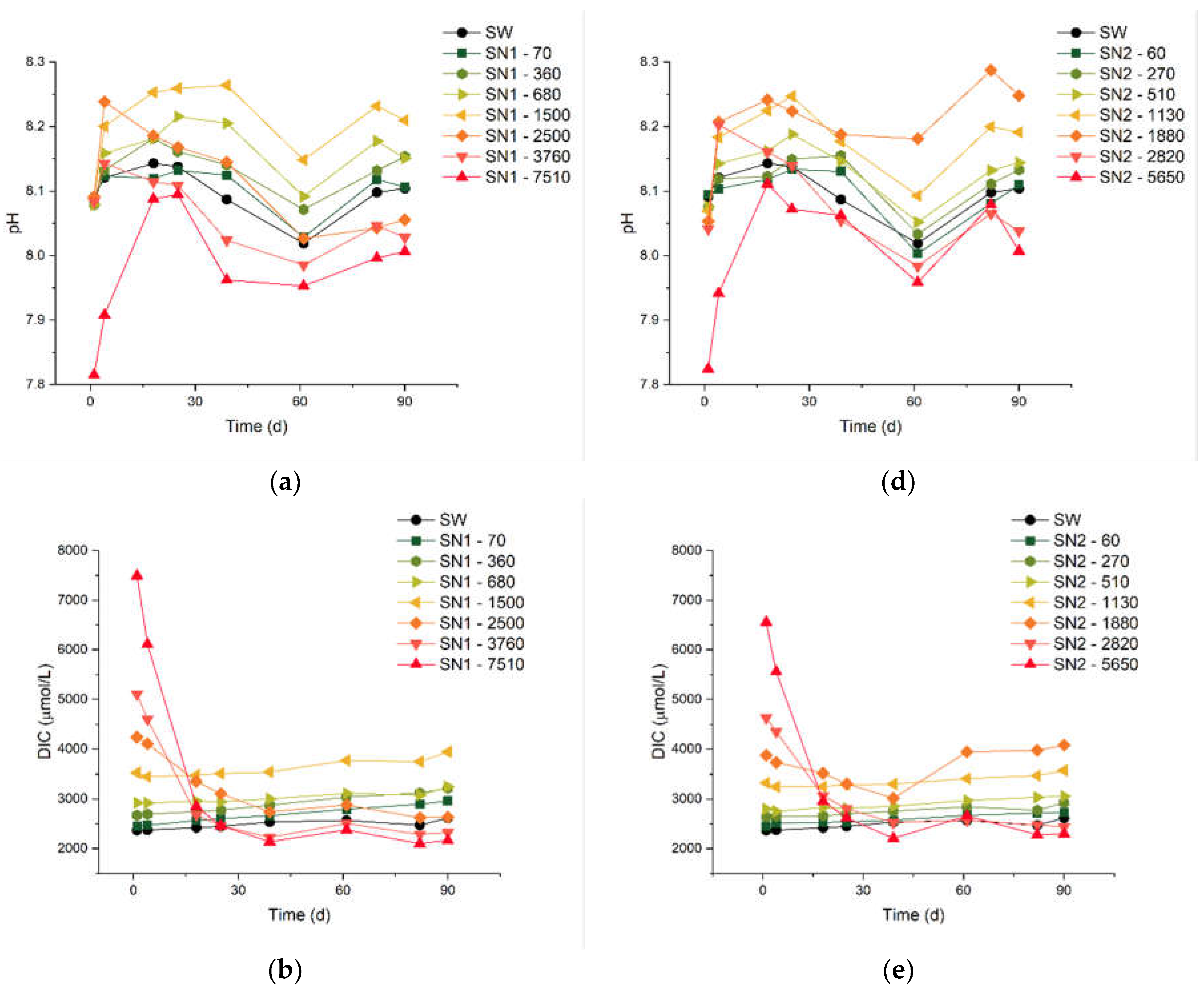
In
Figure 1, we report results from the experiments of types SN1 and SN2, which are characterized by different values of MaxΔ
DIC. The measurements lasted up to 90 days, which is one of the longest periods ever reported in the literature for this kind of studies. The numbers next to each code (e.g., 70 in “SN1 - 70”) indicate the theoretical added DIC, in µmol/L. We measured the pH, DIC and TA, with variable frequency. We also report the results of concomitant control experiments on untreated natural seawater (SW) used as reference. The average starting pH of the SW samples we analysed is ca. 8.1, close to the values reported in the literature for the Mediterranean.[
22]
A few minutes after the initial dissolution (“day 0”), all the samples share the same pH as SW, apart from the two solutions with the highest Δ
DIC (7510 μmol/L for SN1 and 5650 μmol/L for SN2), which feature a lower pH. This is probably caused by a partial precipitation of carbonate minerals occurring in the initial stages of the treatment, before the first pH measurement. Nonetheless, even in these two solutions the pH grows until day 18, when the gap with the other solutions is greatly reduced, even though it remains below that of SW. The pH of the solutions with an added DIC below 270 μmol/L does not show a systematic trend compared to SW, although the differences with respect to SW are always below 0.04, well within the precision limits of the measurements. For solutions with carbon addition between 360 and 1500 μmol/L, the pH is consistently higher than in SW, proportionally to the theoretical concentration. Note that a small increase in pH is expected to be beneficial for the marine environment, considering that the oceans have already undegone significant acidification (the average pH has decreased from 8.11 in 1985 to 8.05 in 2021) due the enhanced absorption of CO
2 from the atmosphere,[
24] and that a surface ocean pH as low as recent times is uncommon in the last two million years. [
25]
The rest of
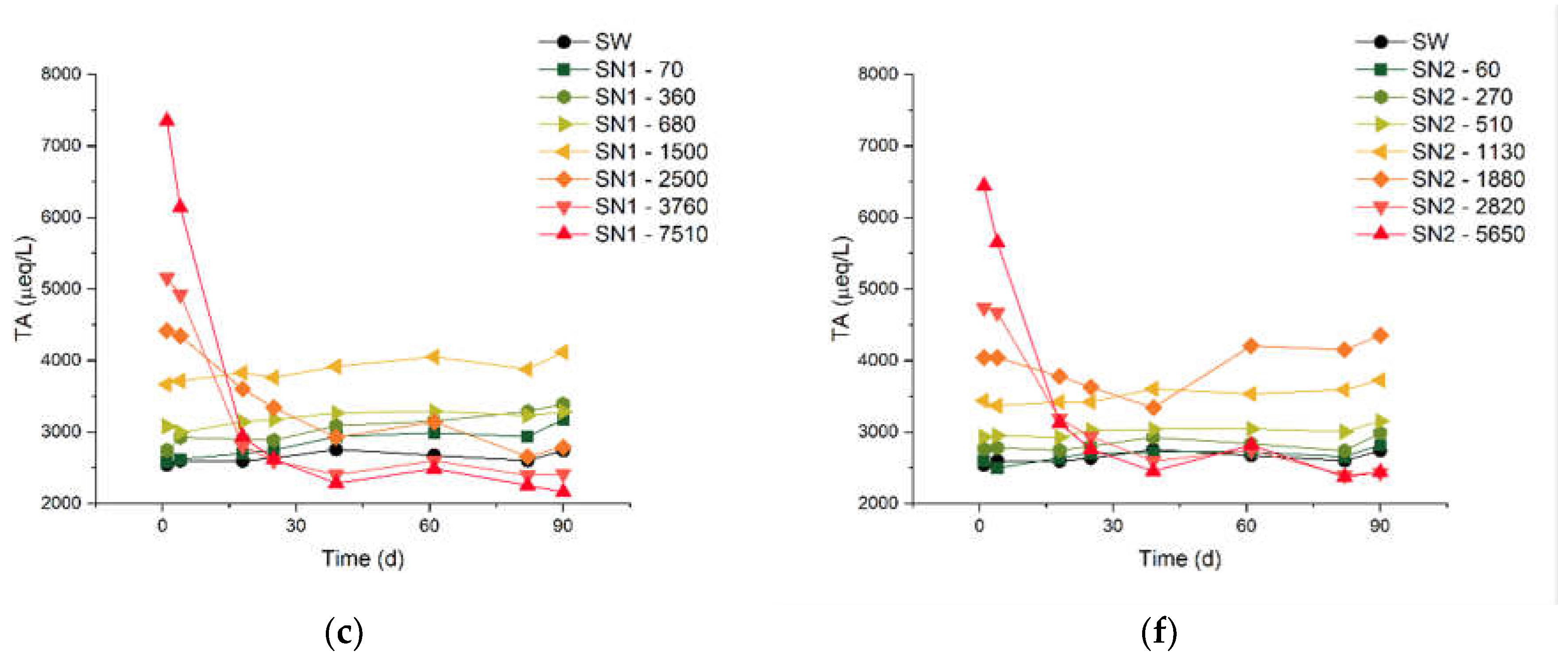
Figure 1 reports results for the DIC [panels (b) and (e)] and the TA [panels (c) and (f)]. The measurements of these quantities started on “day 1”, immediately after the arrival of the seawater samples at our laboratory. The overall behaviour of these quantities is consistent with our pH measurements. In both the SN1 and SN2 series of experiments, the two solutions treated with the largest additions show a decrease of DIC and TA to levels lower than in SW, within approximately 30 days. Note that, for most of the samples, the measurements of DIC indicate values already lower than the sum of the initial DIC and the theoretical Δ
DIC (see again
Table 1). This will be taken into account in the formulation of the process efficiency, below. On the other hand, untreated SW and the solutions with Δ
DIC equal to 1500 µmol/L or lower show a slight increase of TA and DIC for the entire duration of the monitoring.
The precipitation of carbonates from the most concentrated solutions is not surprising, considering the natural supersaturation of seawater.[
22] The saturation states Ω of all solutions under examination can be computed from the measured pH, TA and DIC values,[
6] and it shows some variation. We should consider that the samples were not stored in a temperature-controlled ambient, therefore also the Ω of untreated natural seawater had fluctuations during the control period: the initial Ω was 6.45 and 4.20 for calcite and aragonite, respectively, and the two quantities varied in the ranges 5.15-8.84 (calcite) and 3.34-5.69 (aragonite) without the occurrence of precipitation (
Table A1). Of course, analogous oscillations have also affected the treated solutions. Therefore, for each measurement, we focus on the saturation of the treated solutions (Ω
i) relative to the saturation of the control SW measured on the same day (Ω
SW), using the ratio:
Calcite and aragonite share the same rΩ because the solubility products disappear from the denominators, when computing equation (5).
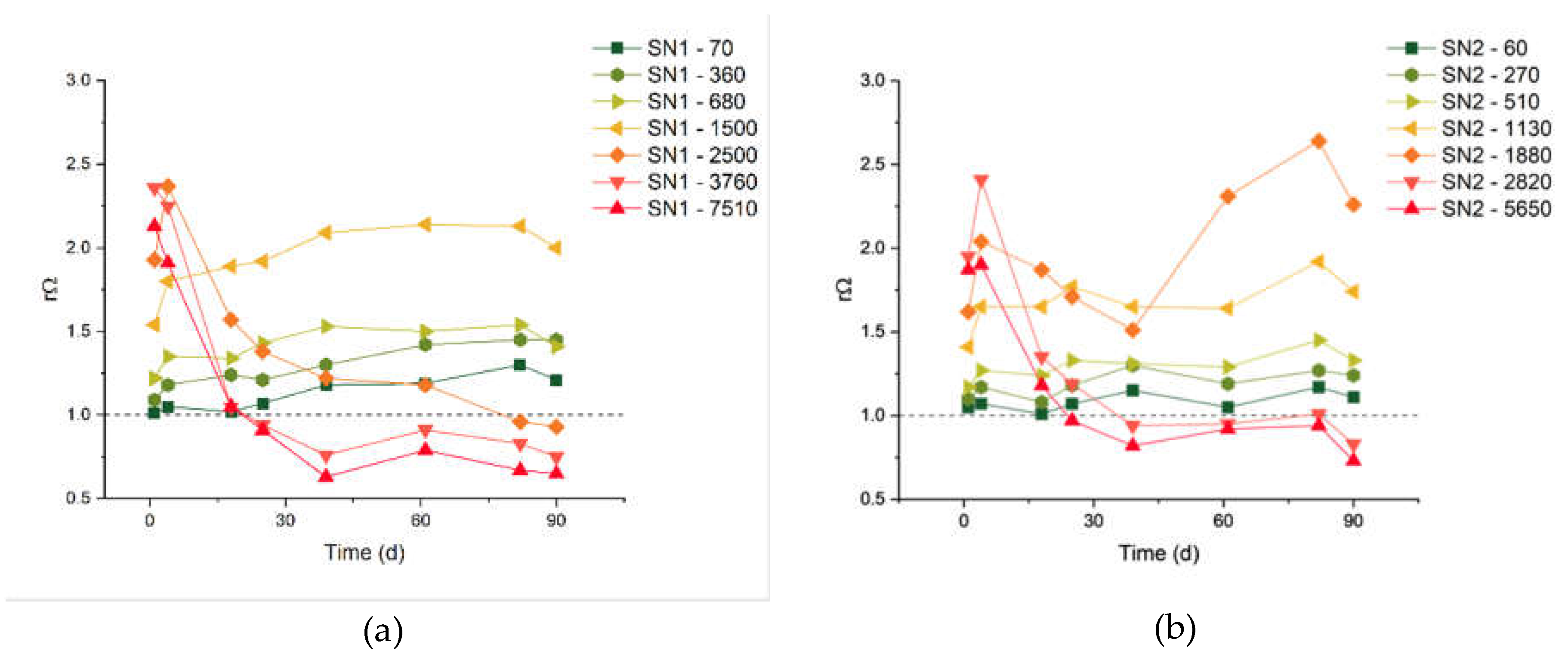
The results are reported in
Figure 2. The samples with carbon additions of 5650 μmol/L and 2820 μmol/L are those with the largest rΩ at day 1, which rapidly decreases due to observed massive precipitation. The samples with carbon additions of 1500 μmol/L (for the SN1 experiments) and 1130 μmol/L (for the SN2 experiments) have the largest stable rΩ values, respectively equal to 1.94 and 1.68 (average values). These could be considered safe threshold values, below which precipitation of carbonate minerals does not occur in our samples.
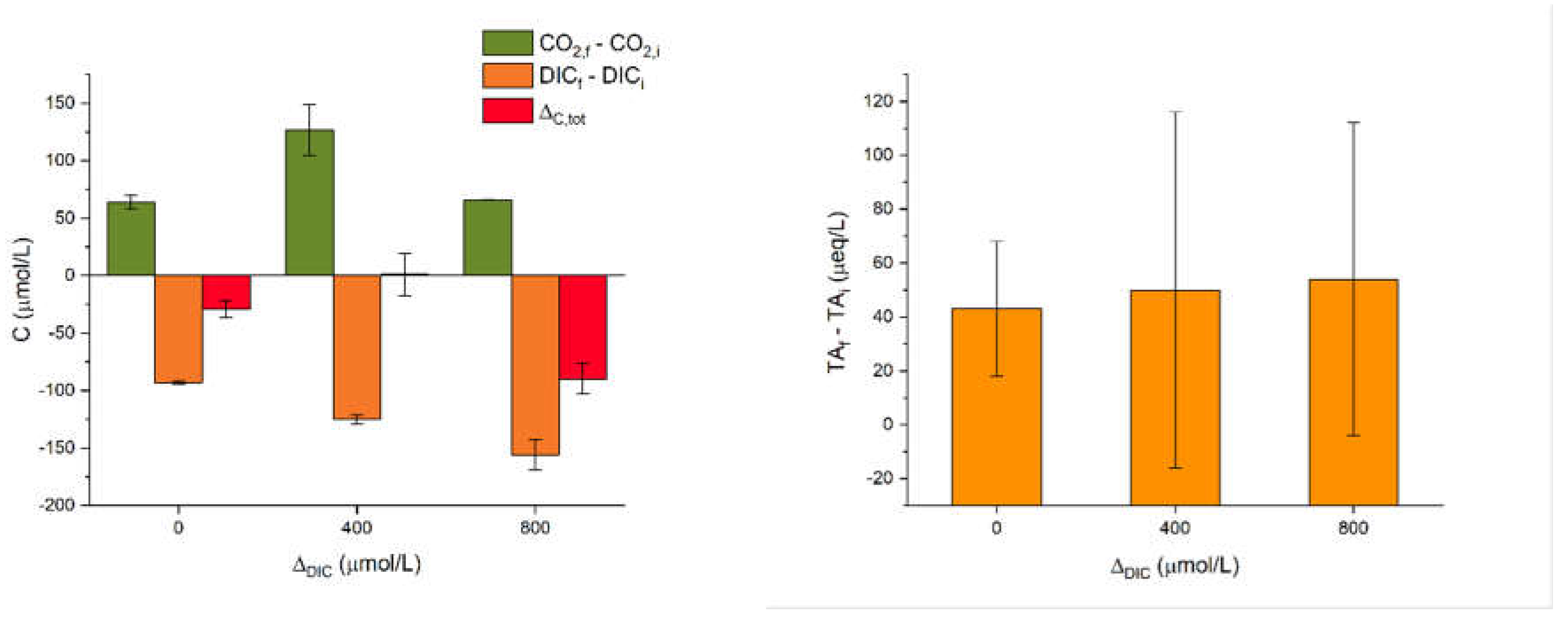
Figure 3 reports results from the SA experiments on artificial seawater with a single addition of alkalinity in the form of NaHCO
3 powder. Namely, we tested carbon concentrations of 2000, 2400 and 2800 µmol/L. Each experiment was repeated twice. Considering the value of 2000 µmol/L as a baseline close to untreated natural seawater (see again
Table 1), these experiments are labelled as Δ
DIC = 0, 400 and 800, respectively. The SA experiments were monitored in a sealed cabinet, which allowed to measure also the CO
2 concentration in the atmosphere. The variation of CO
2 over time should reflect the degassing from the solution.
The pH stabilizes in all the SA experiments, from 7.93 to 8.03. Instead the TA shows sizeable fluctuations, which however are largely due to the technical difficulty of these measurements. As shown in
Figure 3, in all the three additions, the DIC measured just after the dosage decreases at the end of the experiment to about 100-150 µmol/L, depending on the dosage (values reported as DIC
f - DIC
i). This gap increases with the DIC addition, suggesting a degassing of CO
2. This hypothesis is confirmed by the measured increase of atmospheric CO
2 (CO
2,f - CO
2,i), although not consistent with the DIC addition. Overall, we can define Δ
C,tot as the sum of DIC
f - DIC
i and CO
2,f - CO
2,i. We see that all the experiments show a loss of carbon which is not present either in solution or in air. The missing carbon is likely due to minor precipitation of carbonates. We were not able to retrieve the expected quantities in the form of powder after filtration, precisely because these were very small.
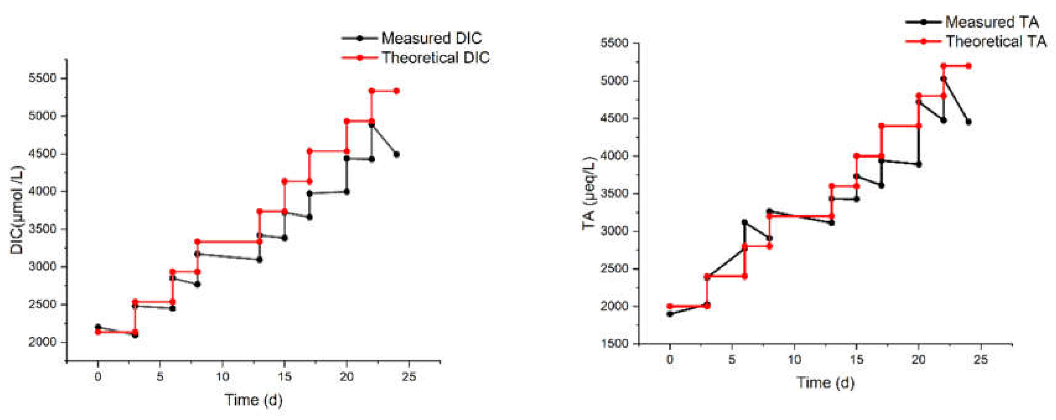
Another laboratory experiment (MAM in
Table 1) was carried out with eight regular additions, again starting from 2000 µmol/L up to a theoretical DIC of 5200 µmol/L (hence, a Δ
DIC of 3200 µmol/L).
The results of the MAM experiment are reported in
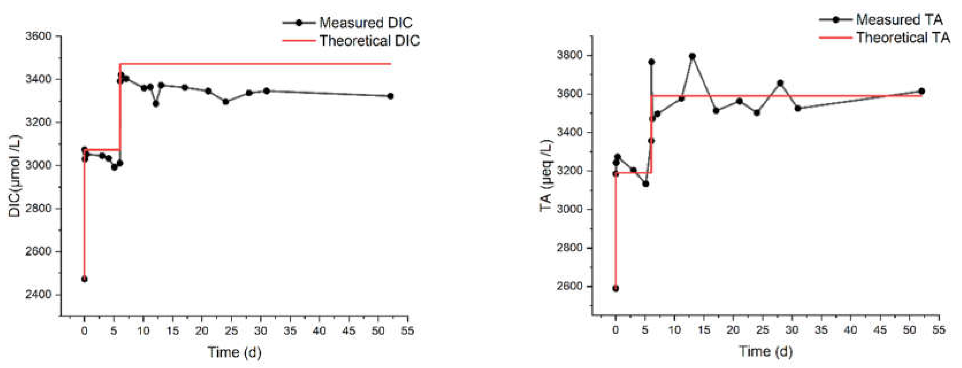
Figure 4. The measured DIC increases, but it is progressively lower than the expected one. It is noteworthy that the last addition did not produce any increase in DIC. The total alkalinity, also shown in
Figure 4, reflects the same behavior of DIC, though with a pair of outliers at day 6, possibly due to a calibration pitfall. It should be considered, in fact, that the precision of DIC measurement (repeated 3-4 times for each sampling) is much superior to that of TA (single measurement for each sampling).
Even accounting for the lower precision, the drop of TA (compared to the theoretical value) seems to be delayed with respect to the drop of DIC. For example, after the third addition on day 8, the TA still matches the theoretical value, while the DIC does not. This may be ascribed to some CO2 degassing occurring already after the first additions, while the loss of carbon by precipitation (with a concurrent decrease of DIC and TA) would be triggered only subsequently. Indeed, the formation of a few particles was visually observed at two stages of the MAM experiments:
1) a few days after the third injection of NaHCO3 (with a theoretical DIC of 3200 µmol/L) some precipitates floated on the surface of the solution;
2) at the endpoint of the experiment (theoretical DIC = 5200 µmol/L), a significant number of precipitates stuck on the wall and bottom of the beaker were observed.
The first episode of precipitation occurred during the longest shift at a fixed concentration, enough to allow precipitation. This is the point where the differences between the measured and the theoretical DIC and TA start to increase significantly. Calculated ΩAr rises from 0.88 (at day 0) to 6.37 (at day 22) and then drops due to precipitation.
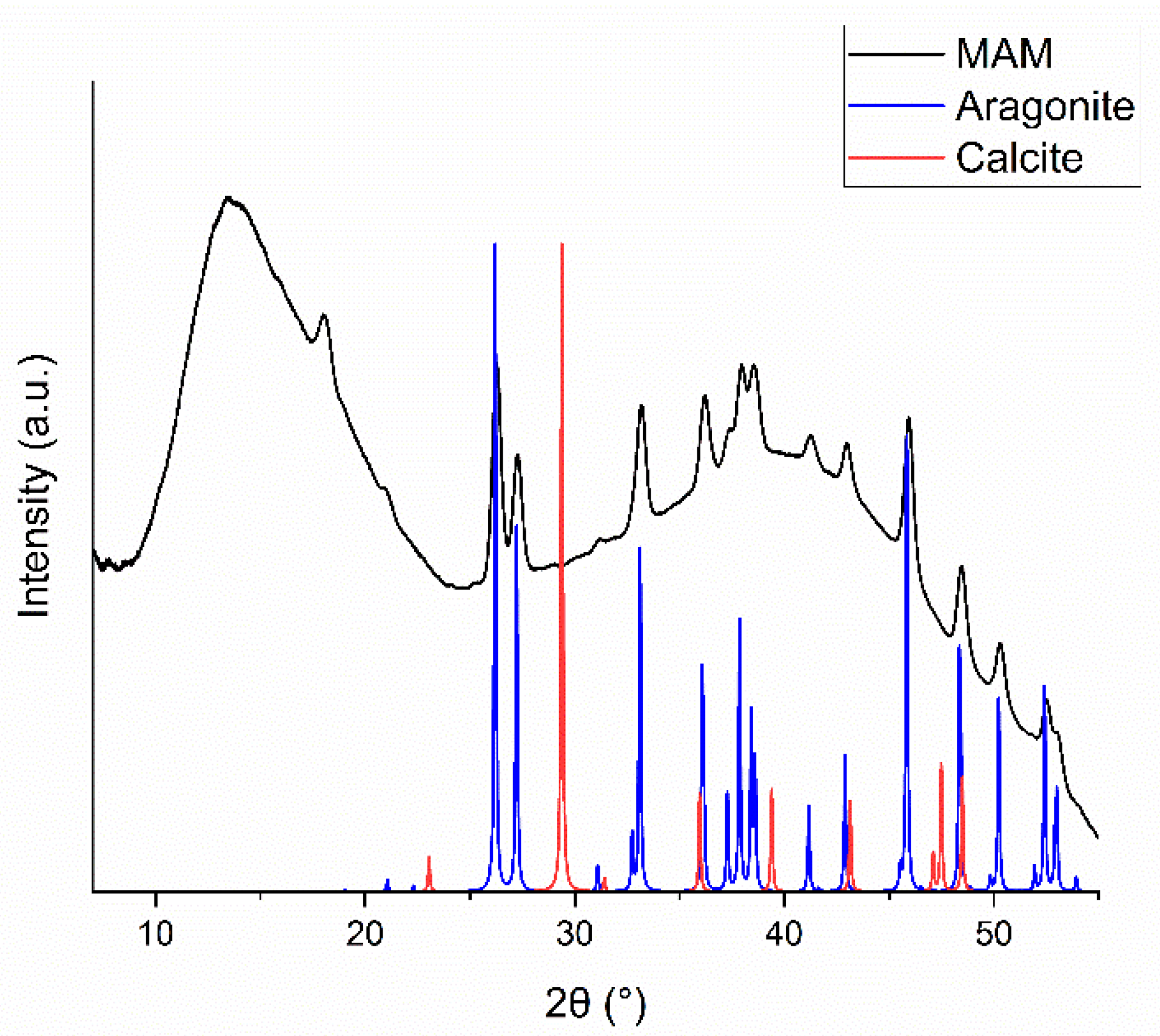
The precipitates from the MAM experiment were collected and analyzed by XRD. The diffraction pattern, shown in
Figure 5, has clear signatures for the presence of aragonite. The large bump at low diffraction angles is mainly due to scattering from the sample holder and air, while the second one at higher angles is likely due to an amorphous carbonate phase and small precipitation nuclei.[
26] From the diffraction pattern it is not possible to recognize any other crystal form than aragonite (and certainly exclude the presence of calcite), despite of the fact that aragonite is more soluble (it has a higher K
SP) than calcite. It is well-known that kinetic factors may dominate over thermodynamic ones in the precipitation of carbonates from seawater.[
27]
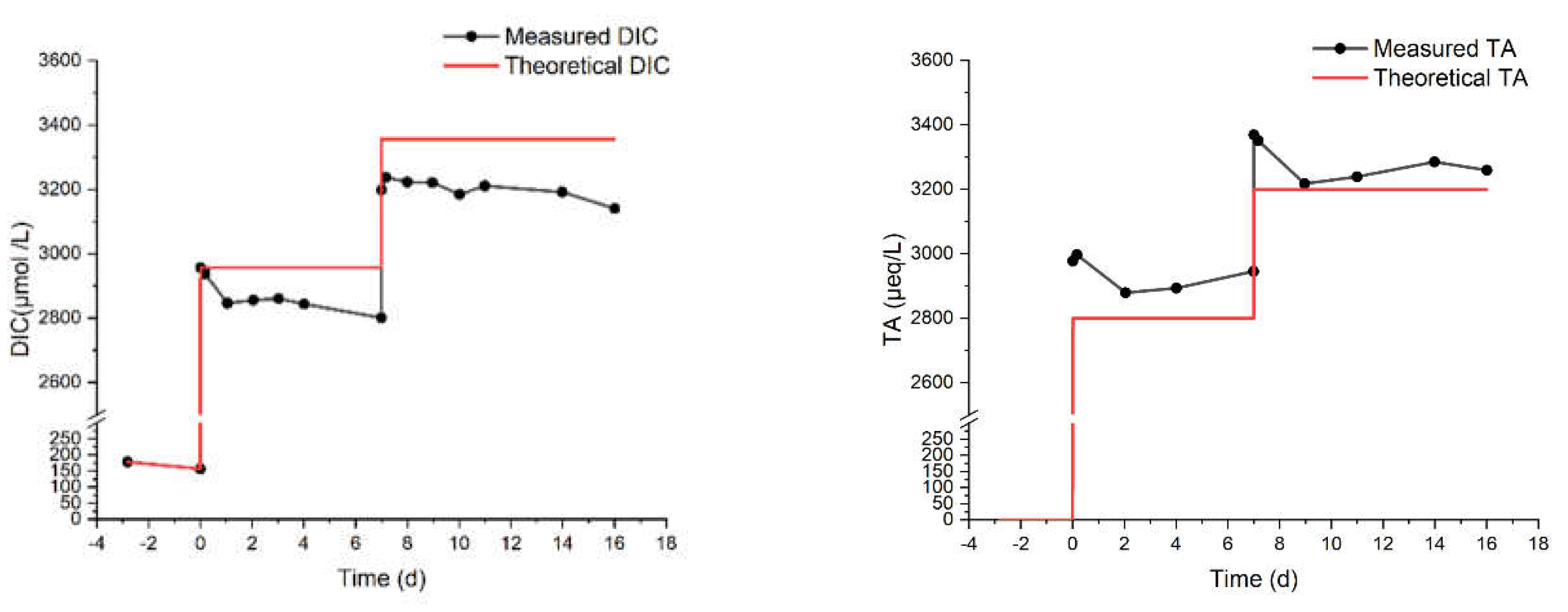
Finally, we describe the MAC and MN experiments. They were carried out to compare the response of artificial and natural seawater against alkalinity addition. These experiments lasted 16 and 52 days, respectively, with an NaHCO
3 addition one week after the start of the experiments. The final theoretical DIC concentration was chosen in both cases to be greater or equal to 3200 µmol/L, which triggered the precipitation of aragonite in the MAM experiments (
Figure 4). The environment was sealed for the entire duration of these experiments. As shown in
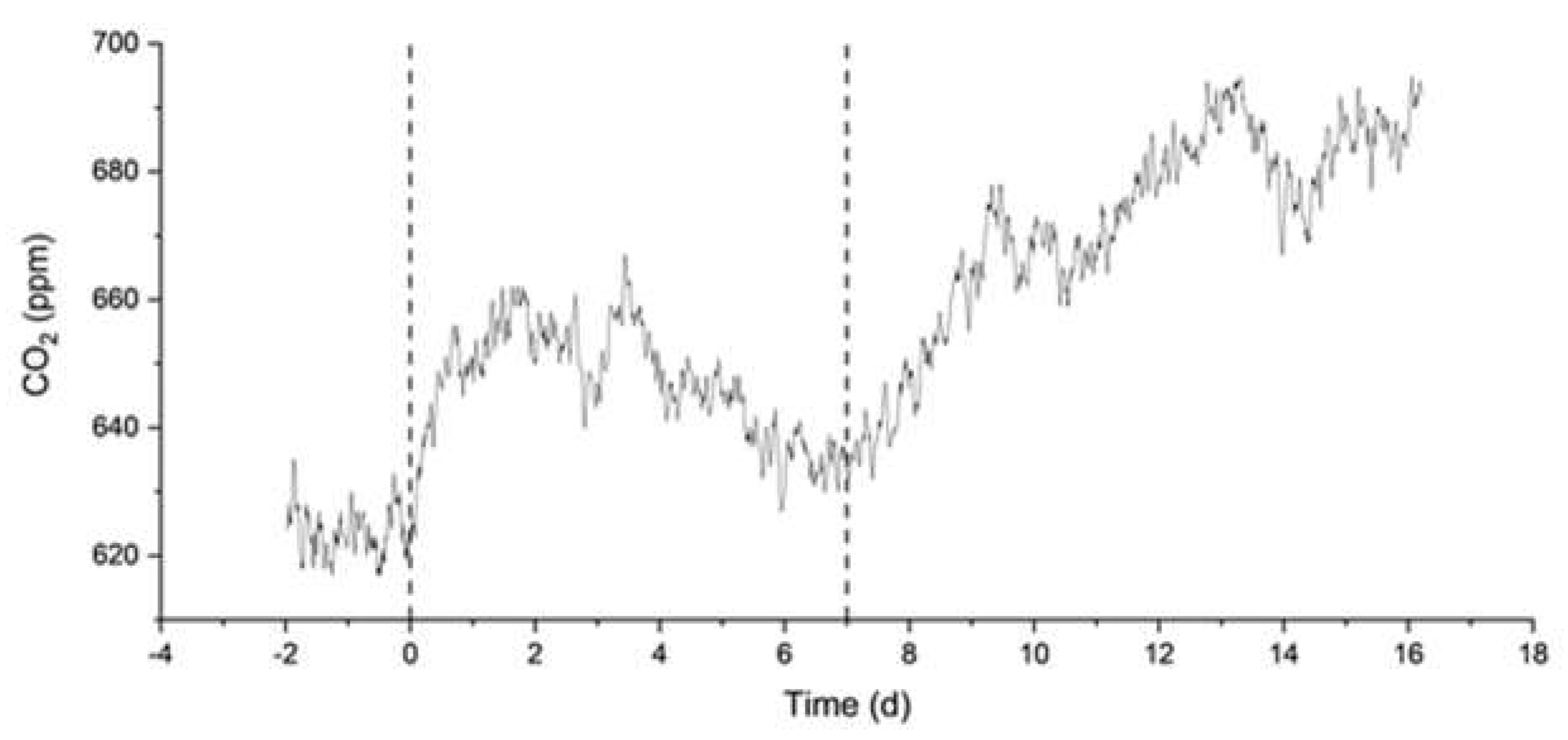
Figure 6, continuous decreases of DIC and TA are observed since the start of the MAC experiment, indicating continuous degassing and precipitation, consistent with the measured increase in CO
2 concentration in the surrounding atmosphere (
Figure 7). The results from the MN experiment in
Figure 8 show a similar trend in DIC, while the measurements of TA are more erratic but stable, which may indicate degassing and, to a lesser extent, some precipitation.
3. Discussion
The experiments described in the previous section enable us to widen the perspective on the processes for treating seawater with buffered solutions enriched with CO2. The overall purpose of the experiments was to assess the efficiency of the alkalinity enhancement process (i.e., the fraction of CO2 that is actually introduced in seawater, mainly as bicarbonates) and its efficacy (i.e., the stability over time of the solutions, without precipitation of minerals or degassing of CO2). Here we concentrate on the discussion of the SN experiments, that are based on the application of the revised BAWL technology implemented by Limenet® on natural seawater.
The hypotheses underlying the BAWL technology that we wanted to test are:
by injecting a CO2 solution pre-equilibrated at the same pH as natural seawater, one induces the least perturbation to the chemical equilibria of the carbonate system and to the natural environment. In particular, pH should remain constant both after the initial treatment and over longer times;
CO2 remains in the seawater solution mainly in the form of bicarbonate, so that the alkalinity and carbon content should increase, without precipitation of mineral phases or degassing of CO2;
the efficiency is high , meaning that the measured increase of DIC matches the added quantity, over a long time.
One major concern for marine sequestration approaches is that seawater is already oversaturated for calcium carbonates, therefore any further addition increases the risk of precipitation and degassing. All results indicate that there is indeed an upper limit, above which it is not possible to increase the carbon content of seawater. This affects the CO2 storage and the method efficiency, i.e. hypotheses b) and c). Below the critical concentration, all the previous interrelated hypotheses are simulatenously verified.
The natural seawater solutions treated with the Limenet
® process had a stable pH around the natural value of 8.1, up to DIC additions of 1500 µmol/L (
Figure 1). Therefore there are no special concerns about hypothesis a). Also the DIC and TA are stable when seawater is treated within this concentration limit, as they show an average variation of 3 to 4%, the same observed for untreated natural seawater.
The DIC and TA drop by more than 60% when seawater is treated with the most concentrated solutions (see more details in
Table A4,
Table A5 and
Table A6). The decrease of carbon content observed for DIC additions > 1500 µmol/L is probably due to a combination of CO
2 degassing and precipitation of carbonate minerals. Once nucleation triggers the precipitation of carbonates, it can quickly proceed to significantly reduce Ω, in addition or in synergy with degasification.
The critical Ω of aragonite and calcite were recognized as important indicators of the likelihood of precipitation.[
20,
21] Marion
et al. [
28] suggested 18.8 and 12.3 for Ω
Ca and Ω
Ar, respectively. In more specific experiments on OAE, Moras
et al. [
20] reported aragonite formation at much lower supersaturations and suggested a safe threshold of Ω
Ar=5 to avoid the “runaway” precipitation. In our SN1-1500 samples, there is no evidence of precipitation even if the Ω
Ar has an average value of 7.7. Such discrepancies among the defined thresholds may originate from a number of factors. First of all, we point out that the supersaturation states are not measured directly, but they are calculated by geochemical softwares that may apply different models. Secondly, one should take into account the specific technologies and chemicals used in the OAE operations, as well as the origin of the seawater (location, temperature, salinity, etc.). Finally, there are factors such as the presence of organic matter, pollutants, colloidal particles and marine organisms that are not taken into account in the evaluation of Ω
Ar, but they can certainly affect precipitation reactions.[
29,
30,
31] For these reasons, here we suggest the increase of Ω relative to that of the starting SW [rΩ, see eq. (5)] as a possible indicator for defining a safe OAE application.
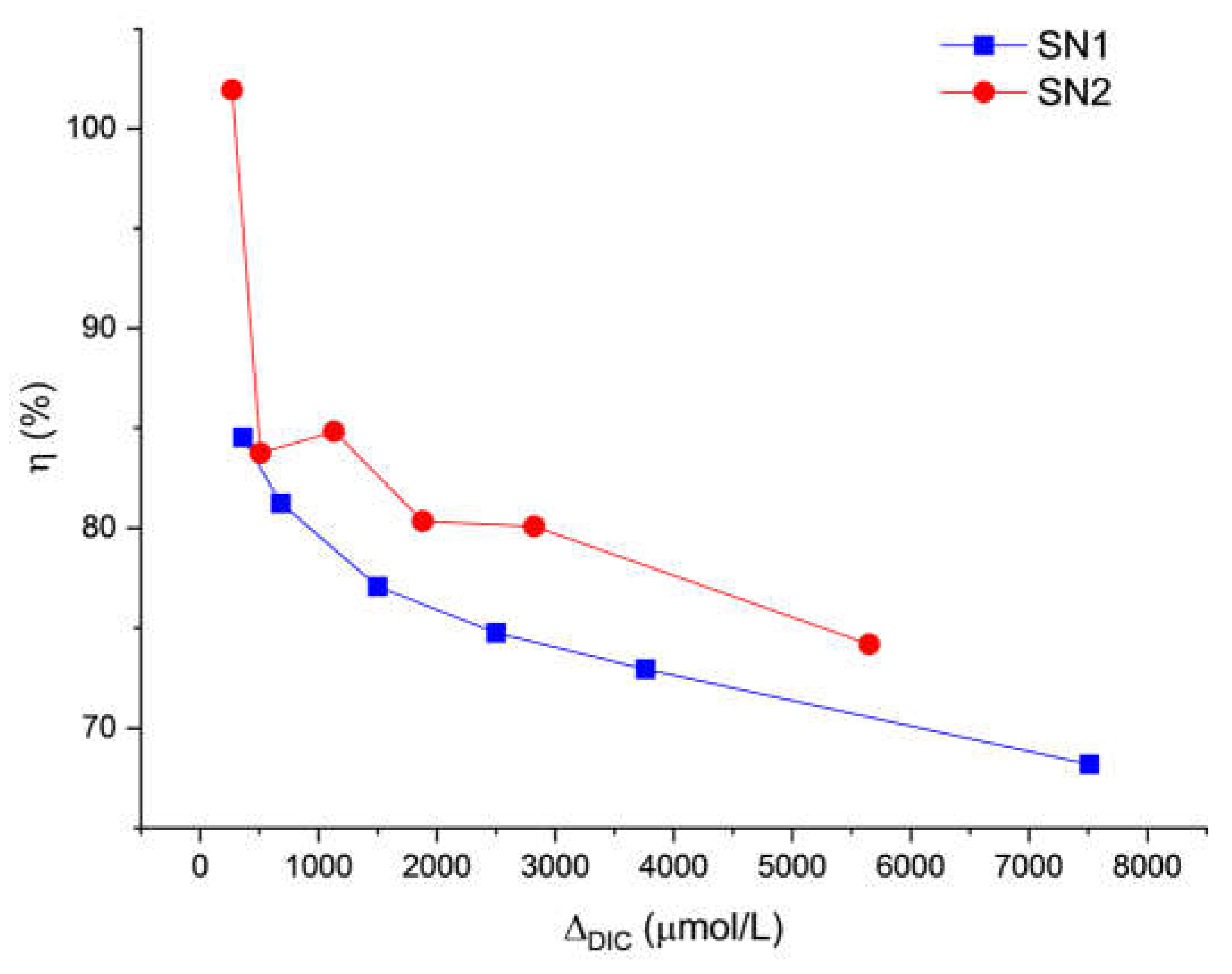
Notwithstanding the different approaches to define the threshold, when the limit is reached, the carbon storage efficiency drops significantly. The efficiency [η(t)] can be defined as the ratio between the observed increase in the carbon content of seawater, and the theoretical one (ΔDIC). Our notation indicates that it is a time-dependent quantity.
Let DIC(t) and DICSW(t) be the measured values of DIC for a given treatment and for untreated natural seawater, measured in the laboratory at the same time t. These two concentrations change in time, also due to processes that are unrelated to the loss of carbon, such as water evaporation and biological activity (the samples were kept in the lab at room temperature, in open glass bottles).
We obtain the efficiency as the product of two factors. The first (
) depends on phenomena occurring during the initial addition of carbon, the second one (
) during the subsequent stability tests:
These are given by:
and:
where:
The value of ƞ
0 takes into account non-idealities that may occur in the reactor and in the line from the reactor to the delivery point, that reduce the amount of carbon taken up by the seawater solutions before discharge. Our estimates, based on the extrapolation of DIC data measured at day 1 (see
Figure 9), lead to
80% for
μmol/L. This value could be increased by optimizing the process parameters. The efficiency of stability includes a correction factor
that takes into account the already mentioned phenomena, which also occur in natural seawater under our laboratory conditions and affect all the DIC values, even though there are unrelated to the loss of carbon.
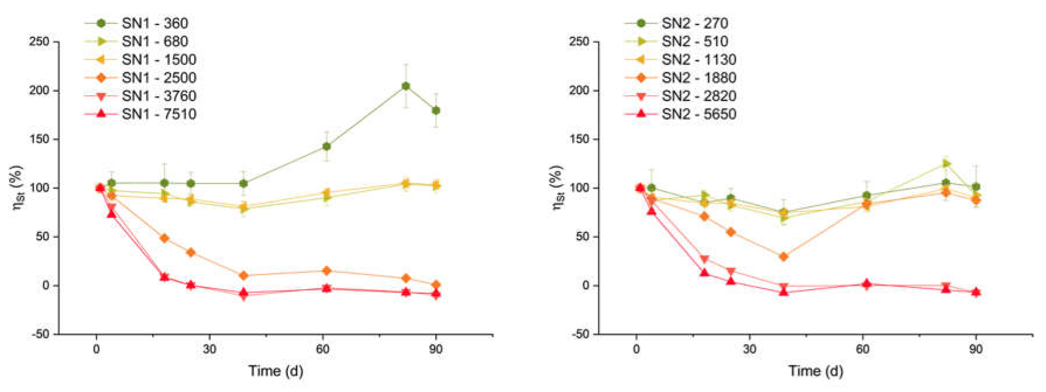
Figure 10 shows the ƞ
St trends for samples with Δ
DIC higher than 270 µmol/L. The data for lower concentrations are not reported here because they are subject to very large errors. All samples with carbon addition between 510 and 1500 µmol/L share a similar trend: an average stability efficiency between 88% and 94%, and a standard deviation of 8%-9% (but for the 510 µmol/L theoretical DIC addition, for which the standard deviation was 16%). This implies an overall process efficiency of the order of 70%.
The sample with ΔDIC equal to 360 µmol/L shows an efficiency that grows far above the 100% limit. This anomalous behaviour is likely due to a contamination of the sample after day 39, as it is not observed in all the other samples.
On the other hand, for the samples with a Δ
DIC higher than 1500 µmol/L, the efficiency drops dramatically within a few days. For the highest concentrations, the efficiency is actually close to zero or even negative. A negative efficiency indicates a final DIC content lower than in untreated seawater. This agrees with the observed decrease of DIC in
Figure 1 and the runaway precipitation of carbonate minerals, similar to the discussion by Moras et al.,[
20] Hartmann et al. [
21] and Varliero et al.[
32]
A final remark on efficiency is related to CO
2 equilibrium with the atmosphere.
Figure 1(a) and 1(d) show a small increase of pH from day 1 to 4, for all the samples, including seawater. This is likely due to the equilibration of the solution with the atmosphere, by degassing. The importance of degassing is also highlighted by the experiments with small Δ
DIC in artificial seawater (SA and MAC, see
Figure 3,
Figure 6 and
Figure 7). In those experiments, atmospheric CO
2 increased without precipitation. Indeed, the pH of artificial seawater is generally lower than that of natural one, so it is understandable that degassing is more prominent.
4. Materials and Methods
4.1. Natural Seawater
Natural seawater has been used for two experiment configurations: single and multiple alkalinity dosages. The seawater has been sampled in two different occasions. Seawater sampling for SN1 and SN2 experiments occurred in September and October 2022 in La Spezia (Liguria, Italy) at CSSN (Naval Support and Experimentation Center coordinates: 44.095863, 9.862471). The MN experiment used water collected in February 2024 always in La Spezia bay (44.1013006, 9.8280323), and stored in glass or polycarbonate Nalgene containers.
4.2. Artificial Seawater
The artificial seawater was prepared by dissolving NaCl, Na
2SO
4, KCl, MgCl
2·6H
2O, and CaCl
2 salts in purified water, with the relative abundances proposed by Roy et al.[
33] Then, it was stored in polycarbonate Nalgene tanks. All salts were Labkem products, purchased from Labbox, and used without further purification.
4.3. Treatment with Ca(HCO3)2
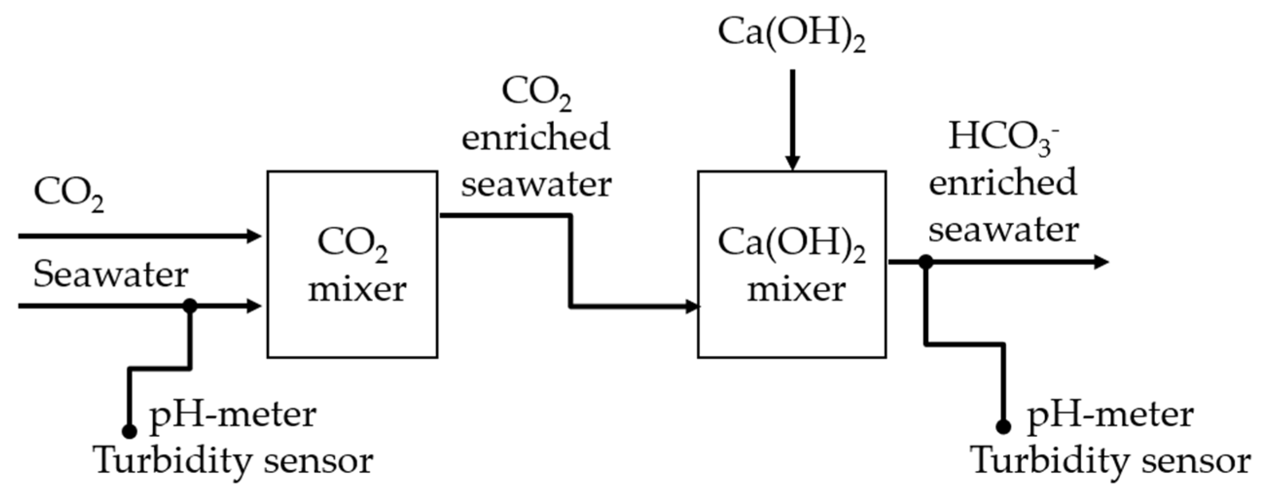
Figure 11 shows a schematic block diagram of the Limenet
® system as implemented in La Spezia. Using a draft pump, about 25 L/s, seawater was collected at a depth of 2 meters. After about 10 seconds, a gaseous stream of 100% CO
2 was injected. After about 180 seconds, a slurry of Ca(OH)
2 was dosed into the acidic stream of seawater and CO
2 to reach the same pH as fresh seawater (i.e., about pH 8.1). The slurry was made of 30 parts of seawater and 1 part of Ca(OH)
2 in weight.
Table 3 summarizes the proportion of seawater, CO
2 and Ca(OH)
2.
pHSense 5-381 and TurbSense SN—TSIR—9667 probes were used to monitor pH and turbidity in the system. CO2 was provided by AirLiquide, while Ca(OH)2 powder by Unicalce.
Three sets of samples were collected: SN1 with a ratio of 3000 m
3/ton between seawater and CO
2; SN2 and SN3 with a ratio of 4000 m
3/ton (see
Table A6 for SN3). The bicarbonate-enriched solutions produced were diluted with fresh seawater, using variable proportions, namely 1:0, 1:1, 1:4, 1:10, 1:20 and 1:100 mass rations between the alkaline solution and the fresh seawater (see
Table 4 for the corresponding Δ
DIC).
After preparation, the containers were capped and transported on the same day to the laboratory of the Department of Chemistry, Politecnico di Milano, without any thermostatic storage device or other conditioning.
DIC and TA analysis was carried out within 24 hours after the collection. It was repeated once a week for one month and then twice a week for the last two months, for a total of 90 days.
Each sample was stored in two 500-mL borosilicate glass bottles and uncapped to allow them to reach equilibrium with CO
2 of the laboratory conditions. On day 1, pH and conductivity measurements were carried out to check the consistency between the two containers. We excluded from the result section the measurements on day 53 because the first bottles of each sample were almost empty and therefore more affected by evaporation. Anyway, in
Figure 1, for some solutions (especially SN2-1880) there is a visible gap between day 39 (last measurement from first bottle) and day 61 (first measurement from second bottle).
4.4. Treatment with NaHCO3
Experiments SA, MAM, MAC and MN took place at the Politecnico di Milano. In these experiments, powdered sodium bicarbonate (NaHCO3) was added to 4.5 L of natural seawater.
NaHCO3 was a Labkem product from Labbox, and used without further purification.
In the SA experiments, sodium bicarbonate was added in a single dosage (2.0, 2.4 and 2.8 mmol/L). 2 mmol/L is the value of NaHCO
3 suggested by Millero[
23] for artificial seawater to mimic the natural seawater pH and alkalinity. These experiments have been repeated twice. Furthermore, a control test, without NaHCO
3 addition, was carried out.
After NaHCO3 addition, the beaker was confined inside a sealed poly(methylmetracrilate) plexiglas cabinet with a volume of 0.335 m3 to avoid exchanges of air with the external environment of the laboratory, having an air/water volumetric ratio equal to 74.3. The windows were opened approximately two hours before the analysis to keep the concentration of CO2 similar among different experiments and to allow the CO2 equilibration.
Probes were placed inside the cabinet to measure continuously pH, conductivity, and temperature of the artificial seawater. A CO2 sensor was used to measure concentration (ppm) of CO2 in the atmosphere inside the cabinet. DIC and alkalinity were analysed before and immediately after the NaHCO3 addition. At the end of the experiment, i.e., after about 48-72 hours, the cabinet was opened, and all the measurements were repeated.
The MAM experiments were performed in artificial seawater. Sodium bicarbonate was dosed in multiple stages, opening the cabinet for dosages and samplings. The addition was done step by step over 24 days, from 2000 to 5200 µmol/L.
MN and MAC experiment were performed with 4L of solution instead of 4.5 L, thus with air/water volumetric ratio of 83.35. The cabinet was closed for the entire duration of the experiments, and sample suction and alkalinity injection were done through a 150 ml syringe by piping from the inside to the outside of the cabinet and controlled by a manually driven valve. NaHCO3 was pre-dissolved in a treated solution sampled by the syringe and then re-injected in the solution. To maintain the volume of the solution, treated seawater samples were kept outside the cabinet and added to replace the seawater sampled for measuring the DIC and TA. Before the first injection, the artificial and natural seawater were equilibrated with air inside the closed cabinet for three and one day, respectively. TA, DIC, pH, and conductivity were measured by periodic sampling, and CO2 concentration in the air was continuously recorded.
For all experiments, temperature was not controlled; the maximum and minimum values recorded during the entire duration of the experiments were about 21 and 16°C, respectively.
4.4. Measurements
Before the first measurements of a new bottle, each sample is vacuum filtrated with sieves of 2-3 μm cut-off to remove large particles that could affect the subsequent analyses. Moreover, filtration allows identification of the precipitates' nature and composition by X-ray diffraction analysis (XRD) using a Rigaku-Synergy-S single-crystal diffractometer. This equipment was necessary given the small amount of precipitate that did not allow a classical powder XRD measurement.
pH and conductivity are measured using electrode sensors of MATTLER TOLEDO Seven excellence. The pH probe was calibrated every two weeks according to the NIST scale, then the values were corrected on the total scale, as suggested by Badocco
et al.[
34]
Total alkalinity was measured by automatic titration (Hanna Instruments HI84531). The pH probe was calibrated every two weeks while the pumping system was every day.
Dissolved Inorganic Carbon was measured by acidification and non-dispersive infrared absorbance (Analytik Jena multi NC 2100S). The machine calculates DIC concentration as the average of three measurements. If the average has a variation coefficient higher than 2%, a fourth measurement is provided, and one is discarded. We verified the calibration by measuring a 2500 µmol/L standard.
Atmospheric CO2 was measured using a sensor (ITSENSOR RCO2-W) located inside the cabinet.
4.5. Speciation and Phase Equilibria Simulation
The supersaturation Ω of aragonite has been calculated with CO2Sys Excel Macro,[
35] version 2.5, using salinity, temperature, DIC and pH as input data to characterize the carbonate system. The software was set on pH total scale, using constants from Mehrbach[
36] refit by Dickson and Millero[
37] for the carbonate system, Dickson[
38] for KHSO
4, and Uppström[
39] for B
T. Practical salinity was calculated from the measured conductivity.[
40] The calculation of Ω in CO2Sys does not consider the variation of Ca
+2 due to the dissolution of Ca(OH)
2 and precipitation of CaCO
3, so the value was corrected as suggested by Moras et al.[
20]
For the experiments in artificial seawater, a set of simulations was performed to determine the concentrations of NaHCO
3. The aim was to ensure that Ω of aragonite did not exceed 5, i.e., the threshold value above which seawater is so oversaturated to cause the precipitation of carbonates and the consequent release of CO
2 in the atmosphere.[
21] These simulations were performed with PHREEQC software version 3.7.0,[
41] with the dataset “phreeqc.dat”.
5. Conclusions
We have presented a series of experiments on bicarbonate-enriched seawater, including both its natural and artificial variants. The aim was to assess the factors affecting the stability and overall efficiency of the storage process, against adverse mechanisms such as CO2 degassing and precipitation of carbonate minerals [see e.g. Equation (3)].
The experiments on natural seawater presented in this work enable us to conclude that, for carbon additions up to 1500 µmol/L, the carbonate system and the carbon storage efficiency are stable over time. In fact, mixing seawater with calcium bicarbonate solutions prepared with the Limenet® process results in a stable preservation of CO2 for over three months. Noteworthy, the duration of these experiments is almost unprecedented for this kind of studies. On the other hand, higher concentrations (with total DIC of ca. 4100 µmol/L, equivalent to a carbon addition of about 1800 µmol/L) may lead to precipitation and loss of efficiency. Experiments on artificial seawater, treated with solid NaHCO3, show precipitation and degassing for an increase of carbon content of ca. 1200 µmol/L, corresponding to a total DIC of 3200 µmol/L.
Considering the uncertainties of our measurements and the environmental variance, we may conclude that a safe limit for the increase of carbon content in our seawater samples is about 1000 µmol/L. It is also important to consider that the precipitation observed above this threshold occurs only after several days. In a real-world application in a marine environment, this delay is likely sufficient to achieve a significant dilution and avoid this pitfall, also for higher DIC additions.
