Preprint
Review

Review – Safety Aspects of Sodium-Ion Batteries: Prospective Analysis from 1st Generation towards More Advanced Systems

Altmetrics

Downloads

214

Views

118

Comments

0

A peer-reviewed article of this preprint also exists.

Submitted:

31 July 2024

Posted:

31 July 2024

You are already at the latest version

Alerts
Abstract
After an introductory reminder of safety concerns pertaining to early rechargeable battery technologies, this review discusses current understandings and challenges of sodium-ion batteries. Sodium-ion technology is now being marketed by industrial promoters who are advocating its workable capacity, use of readily accessible and cheaper key cell components. Often claimed to be safer than lithium-ion cells, currently only limited scientific-sound safety assessment of sodium-ion cells has been performed. However, the predicted sodium-ion development roadmap reveals that significant variants of sodium-ion batteries will potentially enter the market in the near future. With recent experiences of lithium-ion battery failures, sodium-ion battery safety management will constitute a key aspect of successful market penetration. As such this review discusses the safety issues of sodium-ion batteries presenting a twofold innovative perspective: i) in terms of comparison with the parent lithium-ion technology making use of the same working principle and similar flammable non-aqueous solvent basis and ii) anticipating the arrival of innovative sub-chemistries at least partially inspired from successive generations of lithium-ion cells. The authors do hope that the analysis provided will assist the concerned stakeholders in the quest for safe marketing of sodium-ion batteries.
Keywords: 
Subject: Physical Sciences  -   Chemical Physics

1. Introduction

Due to public awareness of limited fuel energy and greenhouse gas emissions by the internal combustion engine vehicles, researchers started to focus on environmentally friendly alternatives and considered decarbonized electrical energy as one of the sustainable options to tackle climate change. However, its use often requires intermediate physical (thermal, mechanical, electrical, chemical, thermochemical, electrochemical or magnetic fields) subsystems to store the produced electrical energy and release it on demand [1,2]. Hence, the concept of using rechargeable batteries was introduced to power electrical devices. In 1859, Gaston Planté invented the lead-acid battery, which showed real road, rail and hydraulic applications with the partnership of Camille Alphonse Faure in 1881 [3]. Lead acid batteries [4] includes toxic lead compounds and corrosive sulphuric acid electrolyte [5]. This raises potential safety concern when exposed under abusive environments and can impact environmental ecosystem. Besides, the lead production from mines causes public health concern [6]. However, owing to its cheap manufacturing, the lead-acid battery still has a dominant market share. Thereafter, Ernst Waldemar Jungner, in 1899, patented the use of alkaline electrolyte [7]. The Ni-Cd cells consisting of nickel hydroxides and cadmium at the positive and negative electrode, respectively, will be banned in the EU with all portable applications from August 2025 [8]. The havoc comes from cadmium metal instructed by the Restriction of Hazardous Substances (RoHS) EU directive 2002/95/EC, due to its carcinogenic nature and the adverse effects it imposes on environment [9]. Compared to Ni-Cd batteries, the Ni-MH batteries consisting of same positive electrode and intermetallic compounds at the negative electrode have 30-40% greater volumetric energy density [10] and are considerably safer and usable for consumer applications. However, the cost of production remains high due to Ni and rare earth metals in these systems and safety precaution must be followed to prevent hydrogen leaking [11].
Following this, the initial research on Li-ion and Na-ion intercalation chemistry started during the 1960s and the 70s [12,13,14]. The first lithium-ion batteries (LiBs) commercially produced by Sony in 1991 contained lithiated cobalt oxide (LiCoO2) as cathode, petroleum coke as anode [15] and aprotic organic carbonate based solvent/lithium hexafluorophosphate (LiPF6) salt electrolytes. They had greater energy density than aforementioned pioneer rechargeable aqueous batteries, hence this led to the dominance of LiBs as the state-of-the-art battery that commands the portable electronic and electric vehicle markets. However, these batteries may undergo so called thermal runaway (TR): Also a very well-known hazard in the chemical industry, battery TR is the incident when temperature of a battery cell increases due to self-heating caused by uncontrollable cascading exothermic reactions [16]. TR leads to flammable and toxic gas venting, and subsequent threats pertaining to fires and explosions events. The severity of these processes depends on the chemistry of electrodes and the electrolyte materials. The most frequently used cathode families of LiBs include layered oxides as LiCoO2 (LCO) [17,18,19], Li[NixCoyAlz]O2, ( x ≥ 0.8, y = 0.1 – 0.15, and z = 0.05) (NCA) and Li[Ni1-x-yCoxMny]O2 (NMC) [20,21,22,23], spinel oxides such as LiMn2O4 (LMO) [24,25] or olivine phosphates [26,27] such as LiFePO4 (LFP) [28]. These materials begin to react exothermically with electrolyte in the 130 - 250 °C range with the thermal stability order of LFP > LMO > NCM111 > NCA > LCO. Ni-rich layered oxides are required for high-energy Li-ion battery technologies, however, their thermal stability decreases with increasing Ni content [29,30]. This instability results from the propensity of Ni4+ at the charge state to spontaneously reduce into Ni2+ [31,32]. This reduction reaction is accompanied by i) a release of singlet oxygen (1Δg or 1O2) reactive species that are oxidizing the electrolyte solvents [33] and ii) phase transitions from a hexagonal to a spinel then rock-salt type phase [34]. The structure instability of Ni-rich layered material is also responsible for the gas generation [35] and thus swelling of the cell when stored at charge state at temperatures slightly higher than room temperature. LiFePO4 is intrinsically considered as safer cathode material than LCO and LMO due to the inherent Fe-P-O bond, which is stronger than Co-O and Mn-O bonds, therefore when exposed to abusive conditions, the oxygen atoms are much harder to remove [36,37,38]. However, this statement must be taken cautiously, since field failure of LFP batteries do also occur, and from flammability and toxicity induced by TR, LFP chemistry was recently reported as more severe than NMC [39]. The selection of the ideal cathode material is still a matter of active research, however in the quest of high performing material, the associated safety must be analyzed simultaneously. The most widely used low-potential anode materials (<0.3 V vs. Li°/Li+) in LiBs is graphite [40,41,42] sometimes added with silicon or silicon oxide (SiOx) to meet high-energy LiBs requirements. The thermal runaway process is initiated by the decomposition of the solid electrolyte interphase (SEI) [16,43] formed from carbonate solvent and additives reduction (< 1.2 V vs. Li°/Li+) on these materials upon first cycles. The TR onset temperature around 80 – 130 °C and heat release at the very beginning mostly depends upon the active material surface area, additives and state of charge (SOC). The spinel lithium titanate, Li4Ti5O12 (LTO) compound [44] whose lithium insertion/deinsertion potential (1.5 V vs. Li°/Li+) is higher than the electrolyte solvent reduction is also used as anode materials [45] for low-energy batteries. In addition to being considered a "zero-strain" electrode material, which guarantees excellent capacity retention, improved safety gain is a promising feature. Belharouak et al [46] investigated the comparative thermal behavior of charged LTO vs. graphite anodes paired with LiMn2O4 cathode full cells. Graphite showed an initial exothermic peak at 100 °C, whereas for LTO it was around 130 °C, moreover the total energy released for the latter was found out to be less than graphite anode.
Despite the dominance of LiBs, sodium-ion batteries (SiBs) are emerging as promising next-generation alternatives to complement the growing energy demand because sodium is widely available, much cheaper and exhibits similar chemistry to that of LiBs. They are considered as the best candidate power sources even if they might lack behind in terms of specific energy due to the higher standard redox potential of Na0/Na+ (-2.71 V vs. SHE) vs. Li0/Li+ (-3.04 V vs. SHE) and the heavier atomic weight of Na (22.9 g.mol-1) vs. Li (6.9 g.mol-1). Recently, sodiated layered transition metal oxides and polyanions have been introduced as cathode materials and hard carbon materials as anodes in SiBs. For instance, developed by the start-up TIAMAT Energy, France, prismatic and cylindrical high-power batteries [47] consisting of a structurally robust polyanionic cathode material Na3V2(PO4)2F3 (NVPF) can be found in the market today with screwdriver as real-life application [48]. The UK-based startup company, Faradion Limited is manufacturing high-energy cells based on the substituted and structurally stabilized layered oxide cathode material, NaaNi(1-x-y-z)MnxMgyTizO2 [49]. This technology, developed in collaboration with Williams Advanced Engineering and Oxford University, is aimed for electronic bikes [50].
The sodiated layered metal oxides positive active material (Na1-xMO2, where M is a transition metal = Mn, Ni, Ti, Zn, Fe, Co and their mixtures) are classified into O3 and P2 type materials [51]. These are based on the oxide layer stacking in octahedral or prismatic environment of Na ions and the numbers 2 and 3 are the transition metal layers with different octahedral coordination stacking in a unit cell [52]. These P2, O3 and nanoscale mixture of O3-P3 or O3-P2 type layered oxide materials can be used in SiBs for medium to high-energy storage applications [53]. P2 type oxides show superior structural integrity and capacity retention, and high Na+ conduction as compared to the O3-type oxides due to huge occupying sites and greater diffusion pathways for Na+ [54]. Because of oxygen presence in the skeleton framework, it is interesting to compare the rate and temperature at which oxygen evolution occurs and how it differs from Li-ion systems. The higher the temperature at which oxygen release from layered oxide cathode occurs, the later sharp temperature increase contributing to TR is observed. Such increase in critical temperature leading to oxygen release can contribute to the overall safety and reliability of battery systems. Polyanionic compounds are also used as sodiated positive active materials. They contain tetrahedron anion units (XO4)n- or their derivatives (XmO3m+1)n- (X = S, P, Si, As, Mo, or W) with strong covalently bonded MOx polyhedra (M = transition metal) [55] which improves the stability of oxygen in the structure thus offering better thermal stability compared to that of layered oxides. Due to the rigidity of the polyanionic structure, the particles show little change in volume during insertion and extraction of Na+ ions, which also enhances their thermal stability. Hence, such active materials must be promoted due to their safety gain and quest on finding ways to increase their energy density must be explored [56,57,58]. Other materials as Prussian blue have also been introduced as cathode materials for SiBs by Natron Energy Technology [59,60]. Prussian blue and its analogs possess the general formula NaxM1[M2(CN)6]y.nH2O, where M1 and M2 are transition metals [61]. The electrochemical performances of Prussian blue analogues (PBAs) are significantly affected by the different transition metals, the intrinsic crystalline water and vacancies in the structure [62]. Due to its poor structural stability, it thermally decomposes to form HCN and cyanogen gas which is equally a major safety hazard [63]. Safety and environmental issues bound to potential byproducts such as HCN and NaCN indeed will deserve due considerations on the full material’s life cycle, as recently discussed by Xiao et al [64]. Currently, it appears that, of the three, layered oxides and polyanionic compounds are leading the race for ideal cathode material for sodium-ion batteries both in terms of electrochemical performance and safety. As for anodes for SiBs, recent developments have used transition metal oxides (or sulfides), intermetallic and organic compounds [65]. However, for the practical utilization of sodium-ion batteries, the low-cost hard carbon (HC) materials remain the state-of-the-art anode material. This carbon type can maintain its disordered structure, in an inert atmosphere, even at a high temperature exceeding 2000 °C, i.e., it is non-graphitizable [66].
The suitable choice of electrolyte, additives and binders is equally as important as the choice of electrode materials for making safe and operational SiBs. The electrolyte and additives form a protective layer at both the cathode and the anode, designated as the Cathode Electrolyte Interphase (CEI) and the Solid Electrolyte Interphase (SEI) respectively [67]. Both these nanometric layers are stabilizing the electrode-electrolyte interfaces [68,69]. Therefore, finding suitable electrolyte formulations is also crucial for developing high-performance SiBs, in terms of capacity, cyclability and safety. Eshetu et al [70] compared the SEI composition of sodiated hard carbons and lithiated graphite with X-ray photoelectron spectroscopy and found out that the sodiated SEI possessed more organic species than lithiated graphite because of the lower Lewis acidity of Na+ (higher solubility) of inorganic sodium salts [71,72]. These results cue that sodium cells have poorer SEI stability upon cycling which poses problems of capacity retention and perhaps also of safety if we consider that the TR onset temperature corresponding to SEI degradation may be faster for SiB than for LiB. On the other hand, sodium salts are more thermally stable than lithium salts [73], hence lesser PF5 and HF might be formed upon thermal decomposition of salt. This might delay or minimize the extent of TR when compared to LiBs, hence, this hypothesis of faster SEI decomposition but lower Tmax reached during TR still need confirmation from more global direct experimental comparison of the two technologies.
When emerging technologies are changing constantly with research and development, the supply chain course might change overtime and influence the market share, hence investigating the safety of the latest technology must be carefully performed and reassessed as far as needed. This review introduces current research on materials and proposes future directions for sodium-ion batteries. On the other hand, despite developments in electrode materials and other components, there remain several challenges, including cell design and cell engineering in the application of sodium-ion cells, this paper will provide insights into scientific and practical issues in the development of SiBs from the safety perspective.
High-energy and high-power battery with targeted applications is desired but one should also equally anticipate its associated thermal and chemical threat. While considering SiB safety aspect and given operational similarity between LiBs and SiBs, one should remember that incidents have paved the commercialization of LiBs since its infancy and that some myths as regard some safety aspects have had to be understood towards better safety considerations in developing electrochemical energy storage systems. Some misconceptions include by the simple choice of adequate “safer” key materials selection (LFP cathode for instance), the TR problem would be solved, however the fact is that the best choice will reduce the chance of TR but not eliminate it. Another myth is that the non-flammable electrolytes would solve the combustibility issue and release of toxic gases during TR, however the definition of non-flammability property is defined conventionally by regulators, may change versus time, and varies regionally. It does not replace field risk analysis considering strengths of potential ignition sources in terms of intensity and duration. Ionic liquids earlier thought to be nonflammable electrolytes due to their negligible vapor pressure are proved to be combustible as well [74].
From early scarce incidents reports of battery fires by the media, nowadays more structured and application-focused incident databases have come up like EV FireSafe platform or the EPRI Battery Electrical Energy Storage Systems (BESS) failure incident database [75,76]. It brings a new insight on the importance of the issue of sharp development of consumer market, as well as high power/energy demanding e-mobility and energy storage applications. Indeed, these structured databases help to learn lessons from past incidents in a scientific-sound manner [77]. Examples of some tragic incidents of battery failure include an EV bus with LiFePO4 power batteries on fire in the charging station on 2015 in Shenzhen, China [78]. Renault-Samsung’s EV SM3.Z.E. caught fire from the front bonnet on 2016 in South Korea [79]. A large explosion and fire in a lithium battery warehouse on 2023 in Rouen, France [80], and a fatal accident in South Korea on 2024 were also reported [81]. Indeed, fatal incidents involving LiBs have occurred on the full life cycle of batteries (from manufacturing to recycling) and in all types of applications from consumer market devices up to large stationary applications. All these hazards correspond to the LiB failure, so will the possibility of a new SiB technology be a boon? It is a million-dollar question with so far rather little to no answer in terms of consolidated evaluation, chiefly when considering the anticipated sharp innovation in the field as reflected by the increasing number of industrial promoters of variants of SiB technology. This was indeed a clear justification of this review work focusing above all on unraveling this question [82]. Establishing what one knows currently on the matter as well as what needs to be further studied to accompany safe development of advanced versions of SiBs seems at the utmost importance. The active materials and its potential associated menace could be tested at the component level followed by cell level to module or pack design in due time for their safe and sustainable developments, two aspects that are from July 2023 key reinforced requirements in the EU since the publication of the new (EU) 2023/1542 Regulation on the matter [83]. This new EU Regulation [84] concerning the applications and repealing the old battery EU directive of 2006 sets new rules towards safe and more sustainable battery value chain by considering the carbon footprint of battery manufacturing, ethical sourcing of precursors and facilitating recycling.

2. Lessons to Be Learnt from LiBs to Develop Thermally Resilient SEI Layer in SiBs

Operational batteries form a nanometric SEI layer on the anode surface typically graphite for LiBs and hard carbons for SiBs. The formation of SEI layer is responsible for the irreversible capacity loss due to electrochemical reduction of electrolyte components during the primary cell cycles [85]. An ideal SEI is electronically insulating to prevent further electrolyte decomposition, ionically conductive to selectively allow transport of Li+ or Na+ ions [86]. This layer must remain electrochemically stable and insoluble over the cycling course [87]. The composition of the SEI formed depends on the material surface chemistry and crystallography, the binder used, the composition of electrolytes (solvents, salts and additives) and the electrochemical procedure adopted (current density, potentiostatic holds, temperature). The SEI formed in sodium-based electrolytes is reported to be less efficient than lithium counterparts with respect to self-discharge, probably due to the higher solubility of SEI components in sodium-based systems [72]. Na2CO3 and NaF, which are often the major components of Na-derived SEI, are reported to be more soluble in organic carbonate solvents than the corresponding Li2CO3 and LiF for Li-based SEI [71]. However, with appropriate electrode and electrolyte engineering this issue could be tackled.
Additives are added to reinforce the SEI. The electrochemical stability window of the electrolyte is defined by oxidation (reduction) potentials related to HOMO (LUMO) levels of electrolyte and additives must lie within these levels [88]. Ideally, additives must have their LUMO energy levels lower than those of electrolyte solvents to reduce before and form an effective SEI layer [89] promoting the long cyclability of the cell. Out of solvents, mostly cyclic carbonates are primarily responsible for SEI formation [90]. Zhang et al studied Na3V2(PO4)3 (NVP) || HC cells independently in EC and PC solvents and found out that the generation of ethene and propene gaseous hydrocarbons corresponding to EC and PC reduction occurs around 2.6-3.1 V (ca. 0.8-0.3 V vs. Na0/Na+), moreover EC solvent reduces on HC around 0.5 V vs. Na0/Na+ in half-cell [91]. Several researches have reported the use of additives such as vinylene carbonate (VC), sodium difluoro(oxalate)borate (NaODFB) [90,92] and fluoroethylene carbonate (FEC) reducing above 0.8 V vs. Na0/Na+, that mitigate the decomposition of the electrolyte at hard carbon electrode by forming an effective SEI layer as supported by DFT calculations. As the onset triggering point during TR is due to decomposition of the SEI layer [93], the study of its thermal behavior is of great interest. These SEI-reinforcing reduction products could be thermally more resistant to breakdown at much higher temperatures [94].
Samigullin et al [95] performed comparative studies of thermal stabilities for Li-ion and Na-ion electrode materials. The electrodes from fully charged state were extracted from lithium and sodium corresponding half-cells comprising 1 M LiPF6 in EC/DMC 1:1 and 1 M NaPF6 in EC/PC 1:1 electrolyte respectively, washed with DMC solvent and dried under vacuum. These dried electrodes were placed in stainless steel crucibles for differential scanning calorimetry (DSC) analysis. The DSC profile obtained in Figure 1a for HC shows two broad peaks between around 150 and 300 °C. These peaks were assigned to SEI decomposition and redox reaction between sodiated HC and poly(vinylidene difluoride) (PVDF) binder.
The authors said that the TR onset temperature of ∼150 °C seems promising from safety point of view, however, as electrodes are washed, the first peak cannot represent the highly exothermic solvent reduction reactions consecutive to SEI decomposition, mostly responsible for the TR triggering. The DSC profile obtained in Figure 1b for lithiated graphite (LiC6) shows a sharp peak around 297 °C (Tonset at 220 °C) corresponding to the redox reaction between LiC6 and PVDF binder. The lithium-titanium spinel (Li4Ti5O12) displays an almost flat DSC curve up to 350 °C and a broad peak around 420 °C with Tonset around 344 °C. This peak might correspond to the combustion of xerogel (solid material formed after evaporative drying of wet gel) precursor and release of CO2 and H2O gases [96].
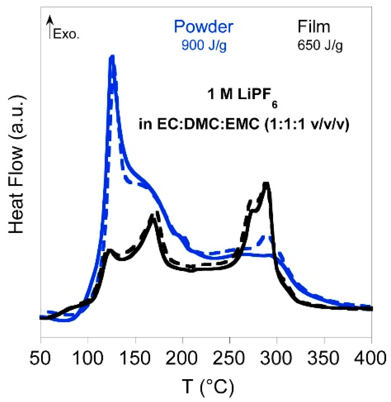
The more realistic SEI breakdown for lithiated graphite was studied by Forestier et al [94] who investigated its thermal behavior in presence of electrolyte. The exothermic heat of reaction was released in the temperature range from 100 °C to 325 °C as shown in Figure 2. The primary exothermic reaction between 100 and 250 °C was attributed to SEI breakdown and solvent reduction. The SEI breakdown was demonstrated to follow acid-base reactions [Equations mainly (1),(2),(3)] between SEI components and PF5 (LiPF6 thermal decomposition product) [94].
Li2CO3 + PF5 → 2LiF + POF3 + CO2
(CH2OCO2Li)2 + PF5 → 2LiF + C2H4F2 + 2POF3 + 2CO2
ROCO2Li + PF5 → LiF + RF + POF3 + CO2 (R=CH3 or C2H5)
It is interesting to compare the SEI breakdown in hard carbon for SiBs and if the thermal decomposition differs from one another. Eshetu et al [73] studied the rate of exothermic heat release of carbonate mixture-based electrolyte with different Na salts as shown in Figure 3.
Irrespective of the salt used, the solvent mixture EC/PC showed the lowest heat release and therefore this mixture would be preferred for safer electrolyte formulation. EC/PC has an improved thermal property due to the intrinsic high polarity of both solvents where Na+ preferentially coordinates with both EC and PC [97]. For solvent mixtures, EC/DEC or EC/DMC, Na+ ions coordinate preferentially to EC and the linear carbonates DEC or DMC diffuse through the porous SEI layer to react with the highly reducing sodiated HC [73]. Even though EC/PC solvent mixture appears to be a safe electrolyte, it must be noted that both are cyclic carbonates with high dielectric constant but high viscosity, hence for practical applications linear carbonates like DMC, DEC or EMC must be added to improve ion transport and ionic conductivity.
Information from DSC analysis regarding exothermic onset temperature linked to SEI breakdown, peak temperature and overall heat generation enables to compare and select safer electrolytes. The SEI layer formed is the result of innate physico-chemical properties of the anode and the electrolyte used. So, by tuning the electrolyte composition, one can expect to some extent to delay the thermal runaway onset temperature. The similarity of the electrochemical processes between the two technologies would lead us to take the example of the most advanced Li-ion technology for a faster choice of electrolytes. However, besides the different nature of the anode material, the potentially higher solubility of the Na-SEI compounds and higher thermal stability of sodium salts compared to Li-counterparts make it challenging to predict the TR onset temperature based on results obtained from LiBs technology. Further in-depth thermal studies, combined with a detailed analysis of the composition of the SEI, are still required for both technologies, in order to be able to anticipate any desirable change in reactivity.

3. Is Zero-Volt Storage Possible for SiBs and What Are the Added Safety Gains?

Sodium-ion batteries can use aluminum for the anode current collector instead of the copper used in LiBs. This change has an impact on over-discharge phenomenon which is an electrical abuse that arises in cell module when there is a voltage imbalance between series-connected cells [98]. During the discharge of a Li-ion cell, the graphite-based anode potential vs. Li/Li+ increases. As copper oxidizes at a potential greater than 3.5 V vs. Li/Li+, it is recommended not to discharge Li-ion batteries to 0 V to avoid reaching this copper dissolution potential [99]. Flügel et al [100] discharged a commercial 18650 Li-ion cell and held it at 0 V for 430 hours and observed that the current collector had visible holes by Cu dissolution. On recharging, the dissolved copper can form copper dendrites, which favors an internal short-circuit in the same way as lithium dendrite, inducing thermal runaway. On the other hand, as the copper current collector of LiB anodes is at around 3V vs. Li°/Li+ in a just-assembled cell, the latter must be charged quickly after to move away from the oxidation potential of Cu, whereas SiBs can be stored appreciably after assembly without cycling.
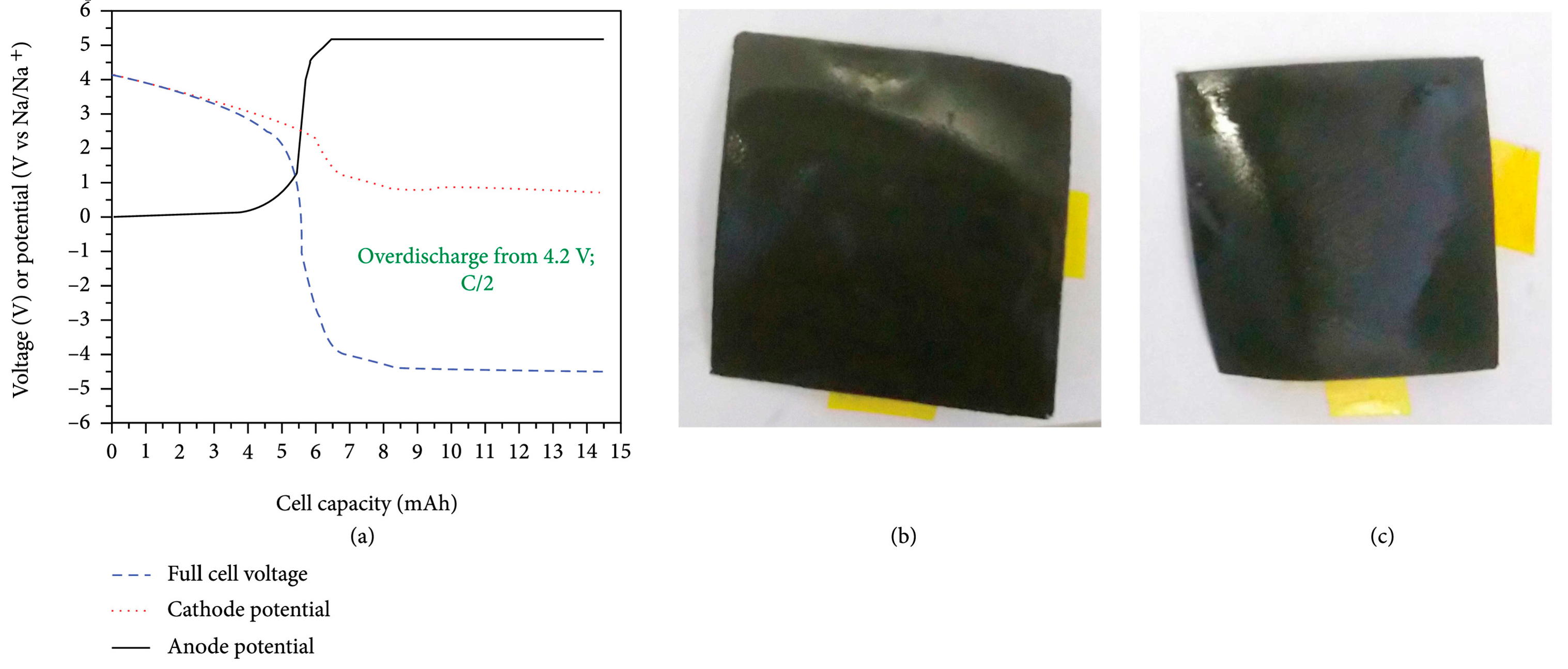
With different chemistries and use of aluminum current collector for SiBs, the collector dissolution process does not occur in SiBs when discharged to 0 V. Rudola et al [101] performed an over-discharge on a 5.5 mAh nominal capacity Na-ion pouch cell with a discharge rate of C/2, results are shown in Figure 4a.
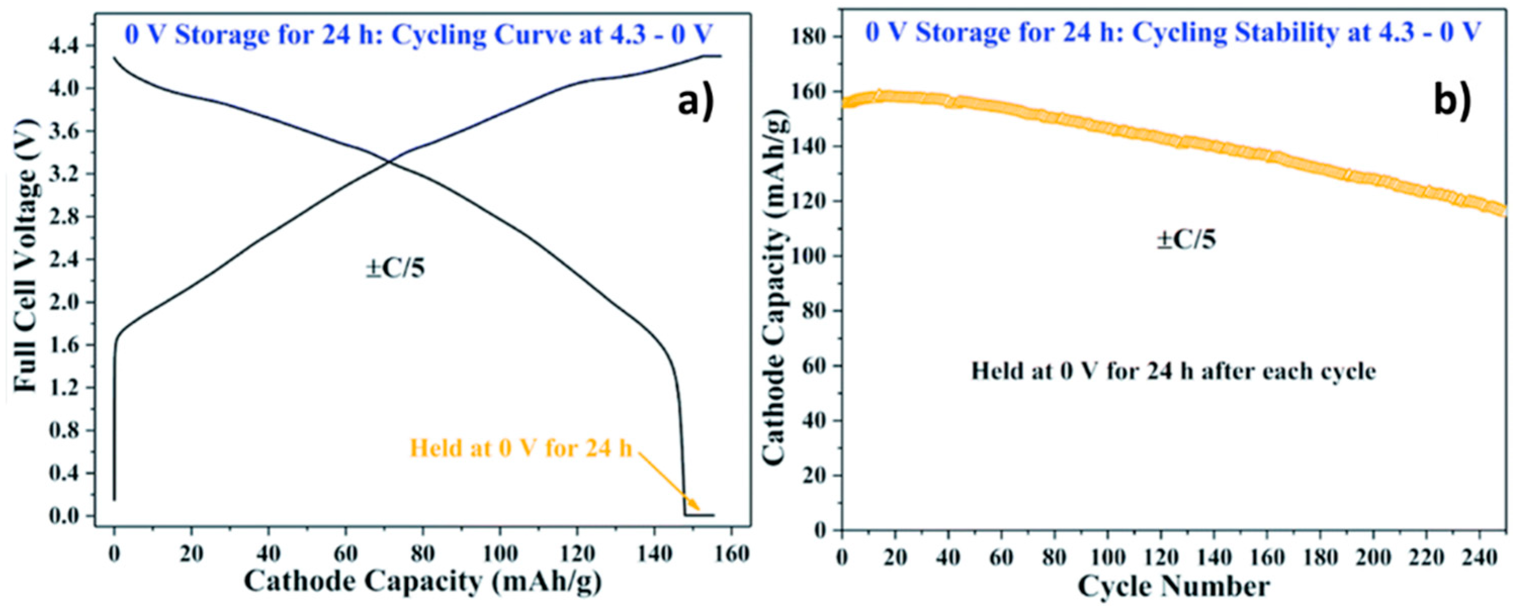
To invigilate extreme worst conditions, the cell was discharged down to negative voltage so that the anode potential arose to 5.2 V vs. Na/Na+, a high potential well beyond the electrochemical stability window of organic electrolytes. The anode potential stayed at this value upon continued discharge due to electrolyte decomposition. As shown in Figure 4b and Figure 4c, no visible decomposition products are observed on anode and cathode surfaces. Another similar study performed by Rudola et al [102] shows the cycling profile of a Faradion Na-ion cell fully discharged down to 0 V and held at this potential for 24 hours (Figure 5a). The cycling stability of this cell cycled between 4.3 and 0 V and held at this low voltage for 24 hours after each cycle (Figure 5b) is not compromised. Considering the above, the zero-volt storage possibility in SiBs might be a boon for safe transportation.
The large demand for electronic devices requires them to be shipped worldwide either by land, air and sea. LiBs are classified under United Nations (UN) category 9 as dangerous goods because they are thermally and electrically unstable when exposed under certain uncontrolled environmental conditions or mishandled during transportation [103]. Hence, when transported, these batteries must follow the applicable regulations according to their mode of transportation: The European agreement concerning the international carriage of dangerous goods by road (ADR), the international carriage of dangerous goods by rail (RID), the international civil aviation organization (ICAO) technical Instructions for the safe transport of dangerous goods by air and the international air transport association (IATA) dangerous goods regulations, the international maritime dangerous goods code (IMDG code) for sea transportation and so on [104]. The higher the SOC during transport, the greater the risk of explosion and thermal runaway. Therefore, during transportation, lower SOC is recommended, however, LiBs have serious complications when discharged down to 0 V as discussed above. A fully charged battery represents the most thermally unstable state. He et al [105] studied the effect of SOC on the self-heating behavior of LiCoO2||graphite prismatic cells. The cells were heated in a mechanically ventilated oven and the presence of flames was detected at SOC ≥ 80%. Hence, transportation of batteries must be strictly prohibited at such high SOC. Hence, to ensure safety and save lives, ICAO and IATA had issued a statement prohibiting the transport of Li-ion cells and batteries at SOC not exceeding 30% [106,107]. With the emerging sodium-ion powered batteries, ICAO has published a joint statement for vehicles powered by SiBs (UN 3558) in addition to LiBs (UN 3556) and lithium metal batteries (UN 3557). Vehicles must have the battery(ies) discharged as far as practicable, and where charge remains, the capacity must not exceed 25% SOC [108] for safe transportation. UN numbers are assigned to each dangerous goods and shipping names based on their hazard classification and composition. LiBs and SiBs are classified into Class 9 assigned as UN numbers 3090, 3091, 3480, 3481 and 3536 and UN numbers 3551 or 3552 respectively [109]. These 4-digit numerical codes designate specific dangerous goods for transport, according to the type of hazard class. It defines provisions for transport in terms of packaging instructions, potential limited quantities per package, and special provisions for transport. Additionally a special provision uniquely for SiBs assigned as UN 3292 allows the transportation of shorted or discharged sodium-ion batteries after sufficient evidence that the electrical or mechanical abuse during its transport do not bring about serious safety hazards [110]. As shown in Figure 4 and Figure 5, the zero-volt storage might be a possibility for SiBs [101,102]. However with discrepancies and arguments among researchers, Desai et al [111] showed that zero-volt storage of SiBs is heavily dependent on cathode cell chemistry and the electrolyte used and is not an innate property for all SiBs. Hence, more advanced studies must be performed to unravel the true zero-volt storage possibility for SiBs.

4. Comparative Thermal Studies of SiBs versus LiBs

4.1. Component Level

4.1.1. Cathode Material

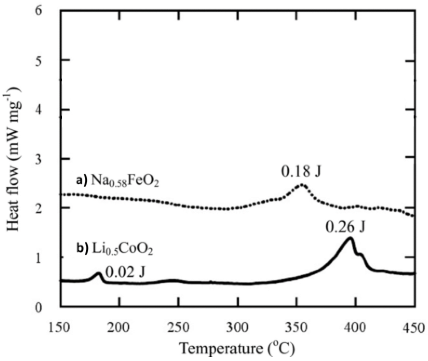
Layered intercalated oxide compounds are used as one of the cathode families for both high-energy SiBs and LiBs. Zhao et al [112] investigated the electrochemical and thermal property of an O3-type layered material, α-NaFeO2 for SiBs and compared it with LiCoO2 cathode material of LiBs. Na0.58FeO2 was formed at the end of the first charged cycle. 57Fe Mössbauer spectrometry confirmed the presence of Fe4+ super iron state on charging making α-NaFeO2 the first iron-based cathode active material based on Fe3+/Fe4+ redox couple. Cobalt is acutely more toxic than iron hence the use of iron-based Na-cathode material is a favorable choice for safer material selection. Further, to check cathode material thermal stability, the desodiated Na0.58FeO2, and delithiated Li0.5CoO2 powders were tested by DSC as shown in Figure 6.
Figure 6a. showed an exothermic peak at 360 °C detected for Na0.58FeO2 desodiated cathode which was supposed to be due to the fact that α-NaFeO2 become thermally unstable through the generation of Fe4+ abnormal valence state. Li0.5CoO2 powder in Figure 6b showed two exothermic peaks at 190 and 395 °C. Those peaks would correspond to the phase transitions from layered rocksalt to spinel and/or rocksalt structures accompanied with oxygen release [29,113]. Thus, suspected similar reactions were supposed to take place for the two materials as shown in Equations (4) and (5).
Li 0.5 CoO 2 0.5   LiCoO 2 + 1 6   Co 3 O 4 + 1 6 O 2
Na 0.58 FeO 2 0.58 NaFeO 2 + 0.21 Fe 2 O 3 + 0.105 O 2
Comparing Na0.58FeO2 and Li0.5CoO2 materials at charged state, the Na cathode shows better thermal stability, no phase transition as for Li cathode, higher Tonset and lower heat generation. These findings prove that Fe-based Na-ion layered cathode is of higher interest than Co-based Li-ion layered cathode in terms of cathode safety.
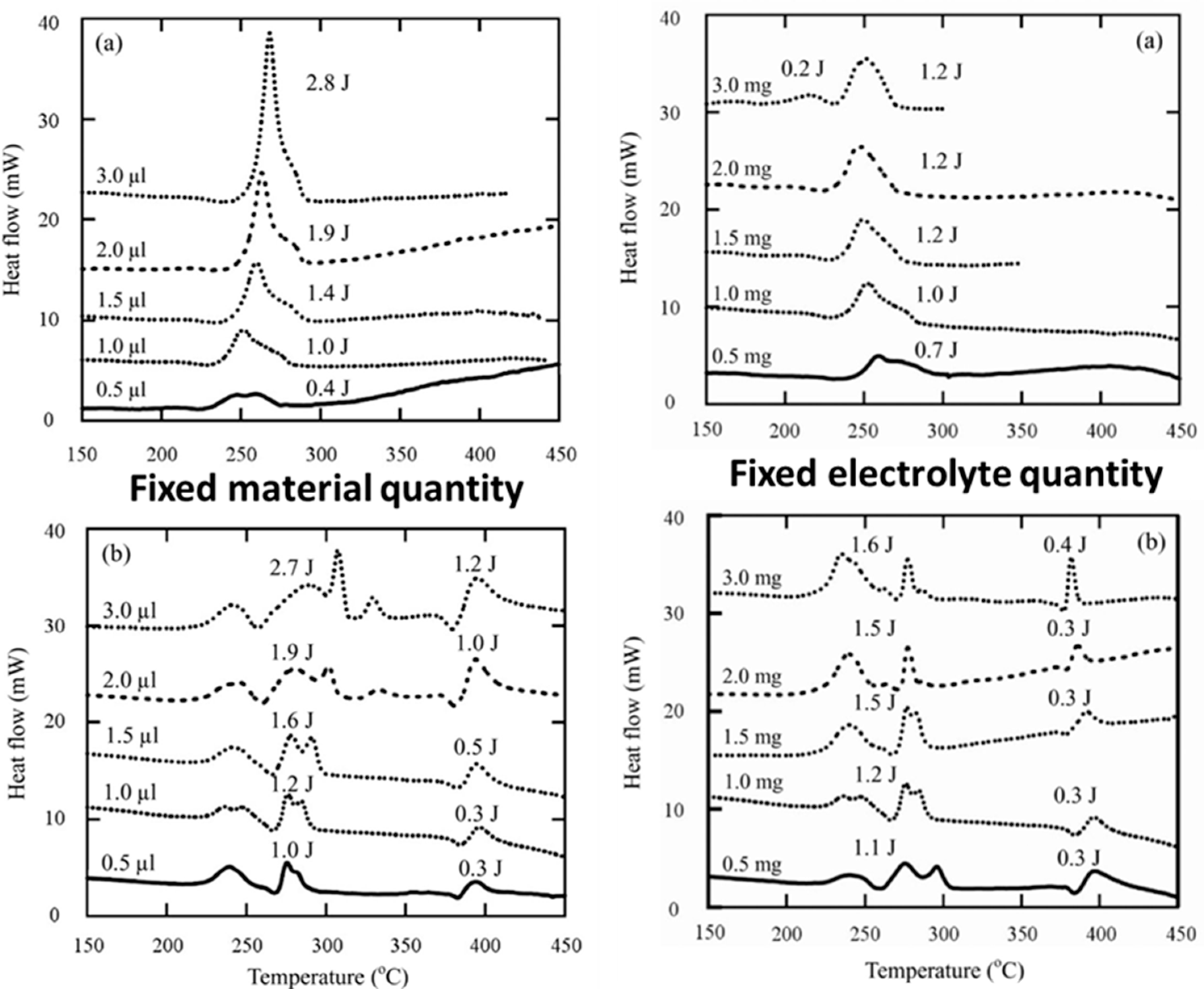
Zhao et al [112] further studied the thermal behavior of these cathode materials in presence of electrolyte as shown in Figure 7 by keeping constant the charged active material or the electrolyte mass.
As observed in Figure 7, the Na and Li layered oxides showed contrasting DSC profiles. For the Na-cathode (Figure 7a, fixed material quantity), on increasing electrolyte quantity from 0.5 µL to 3 µL, the exothermic peak increases and slightly shifts to higher temperature. This suggests that the heat generation is mainly due to the electrolyte thermal decomposition. The mechanism of heat generation from Li0.5CoO2 with electrolyte has been studied well. Co3O4 is formed when Li0.5CoO2 oxygen evolution takes place as shown in equation (4). The following are the chain reactions generated from Co3O4 and EC solvent as shown in [Equations (6),(7),(8),(9)] which have been studied by MacNeil et al by calorimetric techniques (DSC, ARC) and XRD [114,115].
Co 3 O 4   ,   s o l v   3 CoO + 1 2 O 2
5 2     O 2 + ( CH 2 ) 2 OCO 2   3 CO 2 + 2 H 2 O
CoO   , s o l v   Co + 1 2   O 2
2 LiCoO 2 + CO 2 , s o l v Li 2 CO 3 + 2 Co + 3 2   O 2
These series of reactions take place for Li0.5CoO2 with electrolyte from temperature range of 200 to 430 °C, hence their DSC curve (Figure 7b, fixed quantity) appears more complicated than the Na-ion counterpart. Fe2O3 formed in equation (5) from thermal decomposition of Na-cathode might possess improved thermal stability as compared to Co3O4 to prevent the cascading chain of reactions. Hossain et al [116] investigated the thermal stability of Fe2O3 with carbonaceous spheres and TGA/DTA analysis confirmed that an exothermic peak at 462 °C was detected due to the decomposition of γ-Fe2O3 to α-Fe2O3 [117]. The calcined hollow α-Fe2O3 exhibited no weight loss until 1000 °C validating the high thermal stability of the compound. This delayed thermal response of Fe2O3 could attribute to the added safety gain.
Zhao et al [112] studied alternative configuration with varying amounts of Li0.5CoO2 and Na0.58FeO2 charged material with 1 µL of electrolyte, the results are shown in Figure 7 (Fixed electrolyte quantity, a and b). As before, Na0.58FeO2 shows simpler DSC curves than Li0.5CoO2 cathode. The increase in the cathode content mildly increases heat generation but retains peak shape and no major temperature shift is observed from both Li and Na-based cathode. The Na cathode gives off less heat generation in this orientation which is recommendable from safety viewpoint and overabundant cathode had no drastic contribution to heat increase.
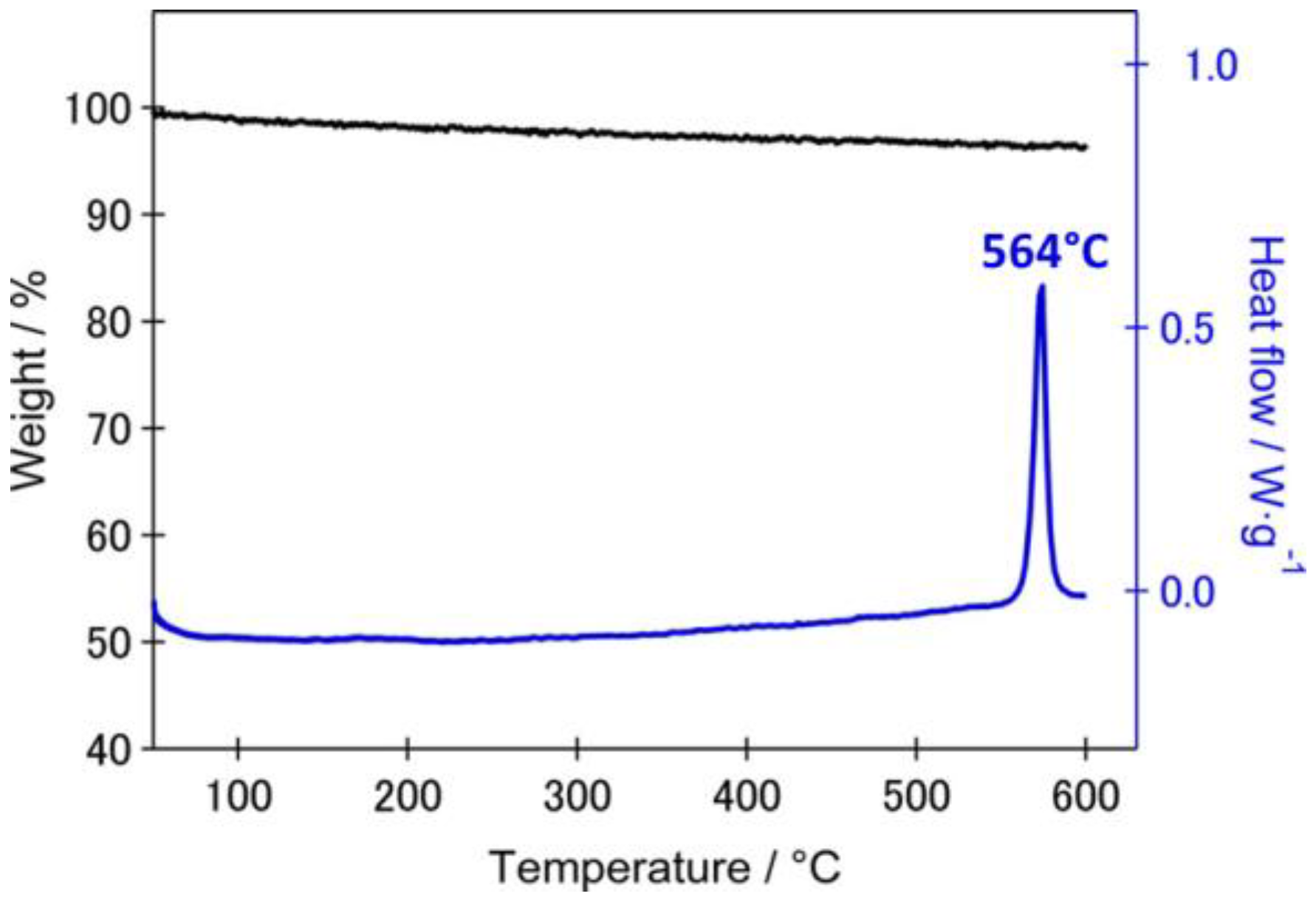
Barpanda et al [118] studied the polyanionic insertion cathode compound, Na2FeP2O7 pyrophosphate. The desodiated cathode composition after charging to a potential of 4 V vs. Na/Na+ was β-NaFeP2O7. The thermal stability of this charged phase was measured by TG-DSC technique. An exothermic peak with onset temperature of 564 °C and heat generation of 16 kJ mol-1 was obtained as shown in Figure 8. The TG curve showed no weight change which inputs the high thermal stability of β-NaFeP2O7. Temperature dependent XRD analysis on the charged cathode revealed that at 560-580 °C an irreversible phase transition from β-NaFeP2O7 (triclinic, P 1 ¯ ) to α-NaFeP2O7 (monoclinic, P21/c) had taken place. This complements the DSC result and answers the exothermic peak generation at 564 °C. The inherent high stability of pyrophosphate (P2O7)4- units could be the reason for high thermal stability. Liu et al [119] also studied the stability of Na3.32Fe2.11Ca0.23(P2O7)2 which falls under pyrophosphate-based Na cathode and observed similar phase transition from triclinic to monoclinic phase with enhanced thermal properties. Additionally, Ca-doping in this particular study enhanced the material’s thermal stability, hence doping could be a good strategy to enhance both capacity retention and structural stability. These researches help promote safe cathode development for sodium-ion battery technology.
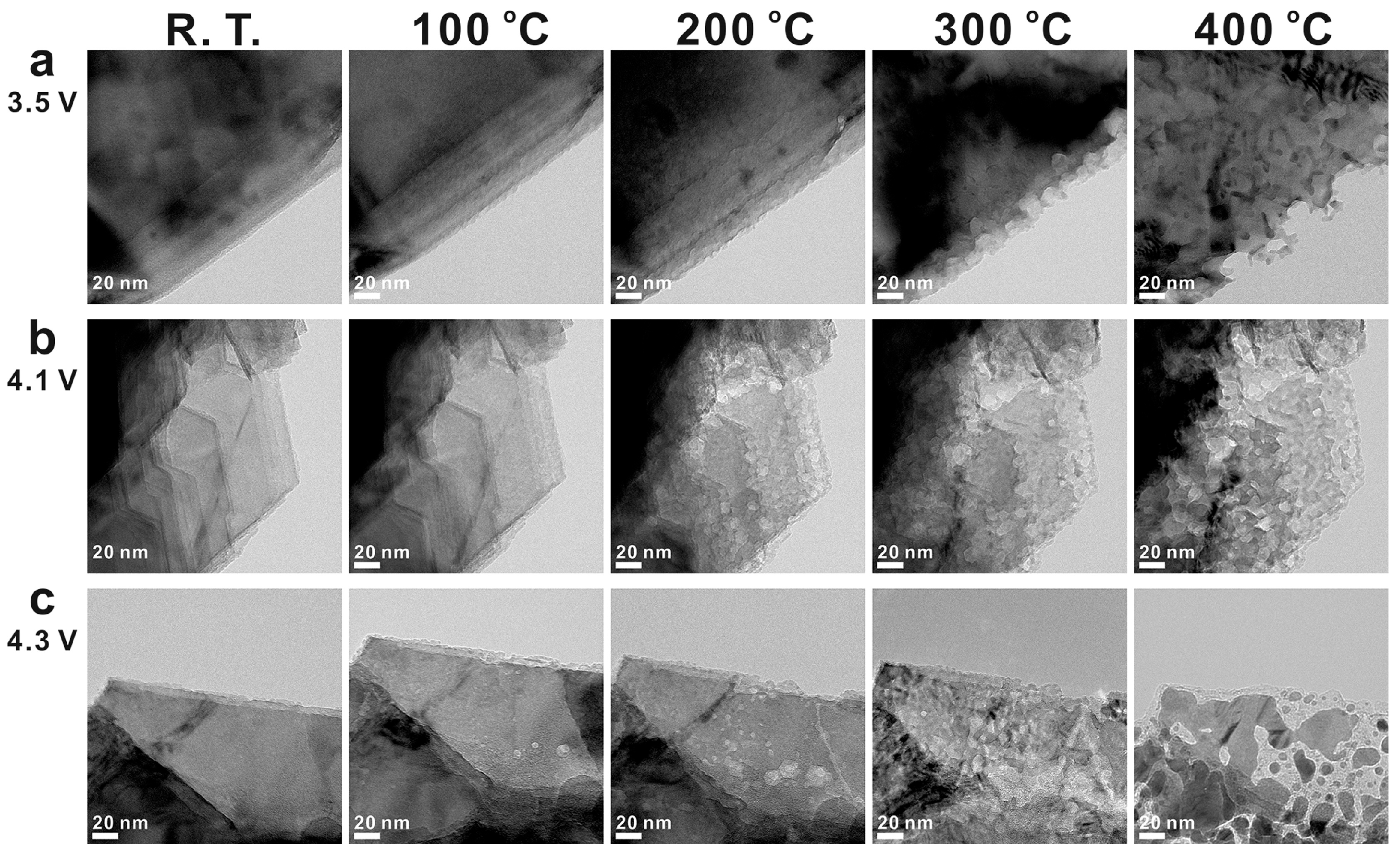
The structural changes of active material and thermal stability may depend on SOC or sodiation/lithiation levels. Hwang et al [120] performed constant charge experiments for layered oxide P2-type Na0.69CoO2 cathode material versus Na metal until the cut off voltages reached 3.5, 4.1 and 4.3 V. It led to the formation of Na0.52CoO2, Na0.24CoO2 and Na0.12CoO2 charged states respectively. The local changes in crystallographic, electronic structures and morphology of charged P2-type NaxCoO2 cathode with temperature ramp was studied using real-time in situ TEM microscopy. The morphology change of NCO materials was tracked by recording bright field images from room temperature to 400 °C. As shown in Figure 9, the NCO morphologies were more severely affected for charged materials at higher SOC and exposed to higher temperature likely due to the complicated series of phase transitions of layered oxide materials at these voltages.
The crystal phases corresponding to each temperature was determined from selected area electron diffraction (SEAD) patterns. The desodiated NaxCoO2 cathode decomposed to Co3O4 and CoO or metallic Co at very high temperatures. The Co3O4 phase was found only at 400 °C for the sample charged to 3.5 V, on the contrary, the Co3O4 phase was found even at 100 °C for those samples charged to 4.3 V. For the harshest condition of 4.3 V and 400 °C used in this study, significant morphology changes, as well as reduction of cobalt oxide to metallic state and loss of oxygen from the structure were observed. These are serious threats to the battery system; however, one needs to go to high voltages (here 4.3 V) to access the maximum capacity to store more energy but reaching high voltages seems detrimental from thermal runaway point of view. Hence, in the quest of finding SiBs with enhanced electrochemical performances, it is crucial to find a balance between producing high-energy or power batteries and safety managements constraints.

4.1.2. Electrolytes

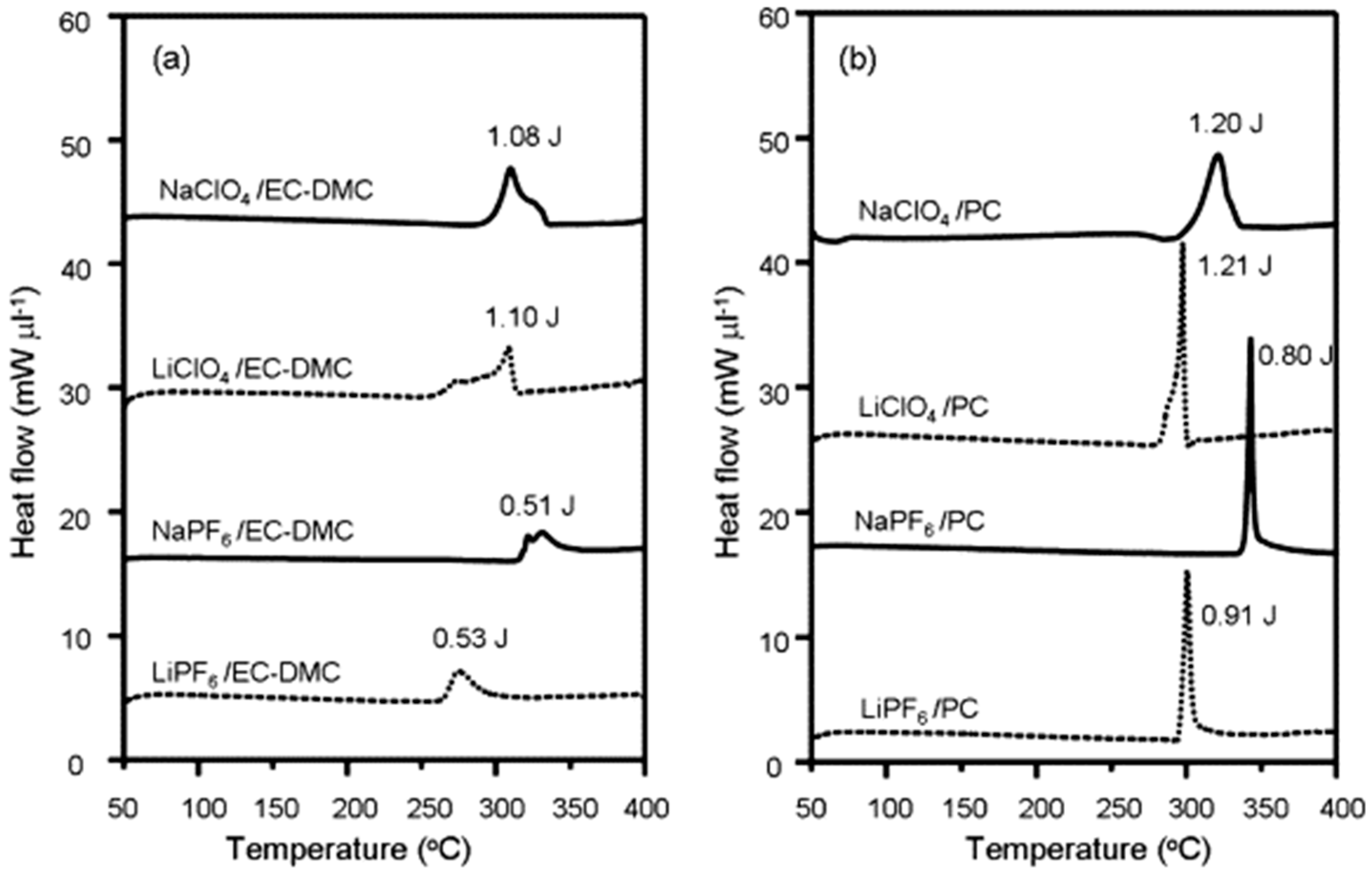
Zhao et al [121] studied the thermal stability of Na electrolytes and compared with Li electrolytes with TG-DSC technique. The thermal stability of electrolytes is dominated by the solvent used. NaClO4 and NaPF6 salts were tested in both EC-DMC solvent mixture and PC solvent with the corresponding synonym formulation for Li-electrolytes as shown in Figure 10. The results show that the PC based solvent generated larger heat of formation than EC-DMC based solvents, however the average onset temperature for EC-DMC solvents is about 25 °C lower than PC-based solvents. These studies also reveal that Na-salt electrolytes generate around the same heat and increased onset temperature (ca. + 20-50 °C) than corresponding Li-salt electrolytes. This explains the better thermal stability of Na-salt electrolytes which paves improved safety in case of thermal runaway.
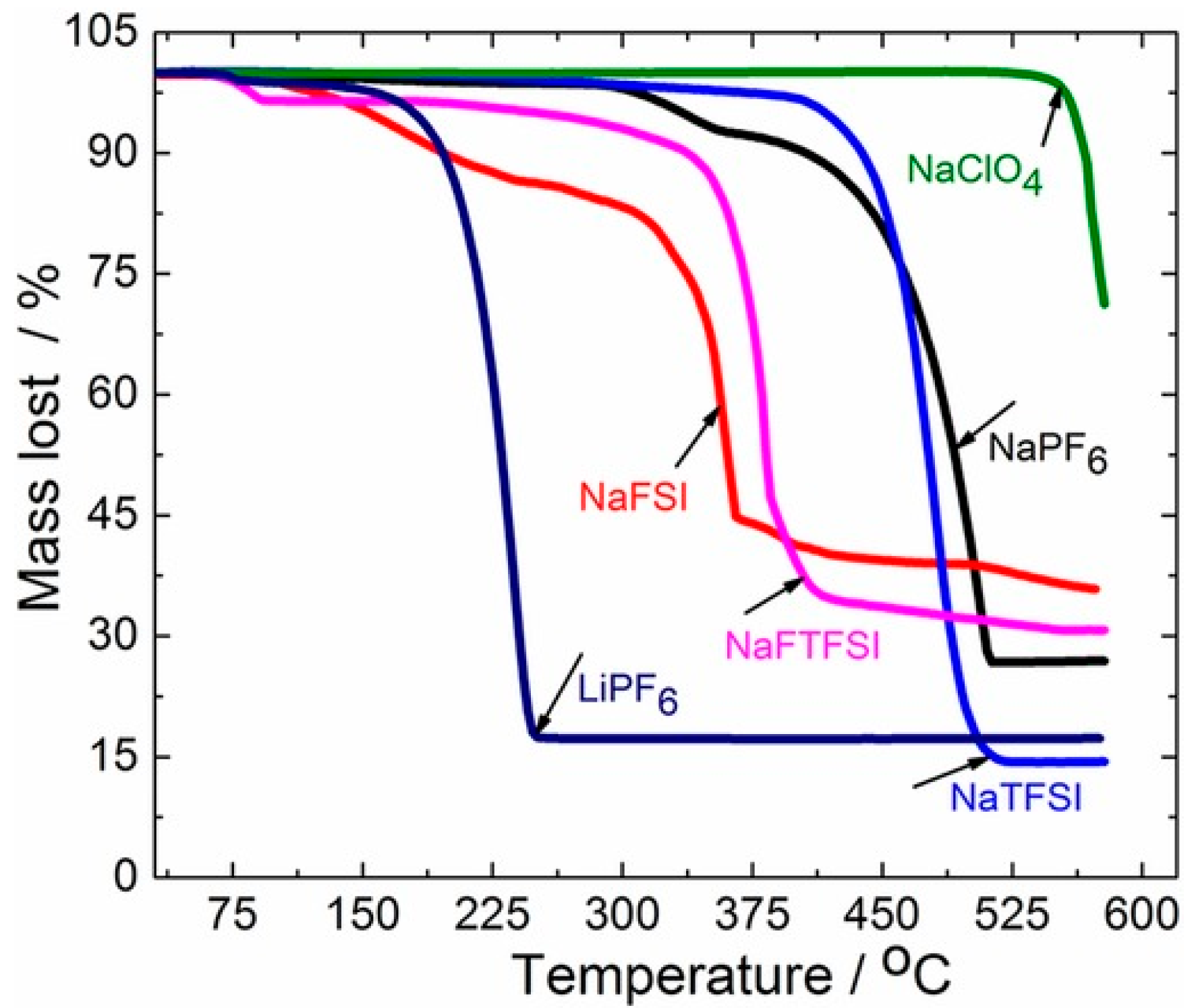
Eshetu et al [73] studied the thermal reactivity of Na-based salts by TG analysis and showed that Na salts are much more thermally stable than corresponding Li salts. As shown in Figure 11, the thermal stability of the Na salts decreases in the order of NaClO4 > NaTFSI > NaPF6 > NaFTFSI > NaFSI. Even though NaClO4 outperforms other salts, it is generally a strong oxidizing agent and explosively decomposes over 130 °C in the dry state [122]. Hence, its use must be limited and exploring other alternatives are recommended. A comparison between LiPF6 and NaPF6 salts indicates that their decomposition starts around 125 and 325 °C respectively, this is true for most of the equivalent Li and Na salts. Na salts are much more stable than the homologous Li salts, explained by higher Madelung energy, a parameter linked to the electrostatic energy in ionic crystals. Moreover, as obtained in Figure 11, LiPF6 salt loses ∼ 83% of its mass at 250 °C whereas NaPF6 salt does not show observable change up to 300 °C. It is worth noting that the thermal degradation of Li(Na)PF6 leads to the formation of the Lewis acid PF5 which adversely reacts towards the basic salts of the SEI in batteries or water from environmental air to yield HF. Besides the gain in intrinsic safety, these results also indicate that SiBs might perform better than LiBs in long-term capacity retention and storage at high temperature which could be one of the potential applications of the emerging SiBs.
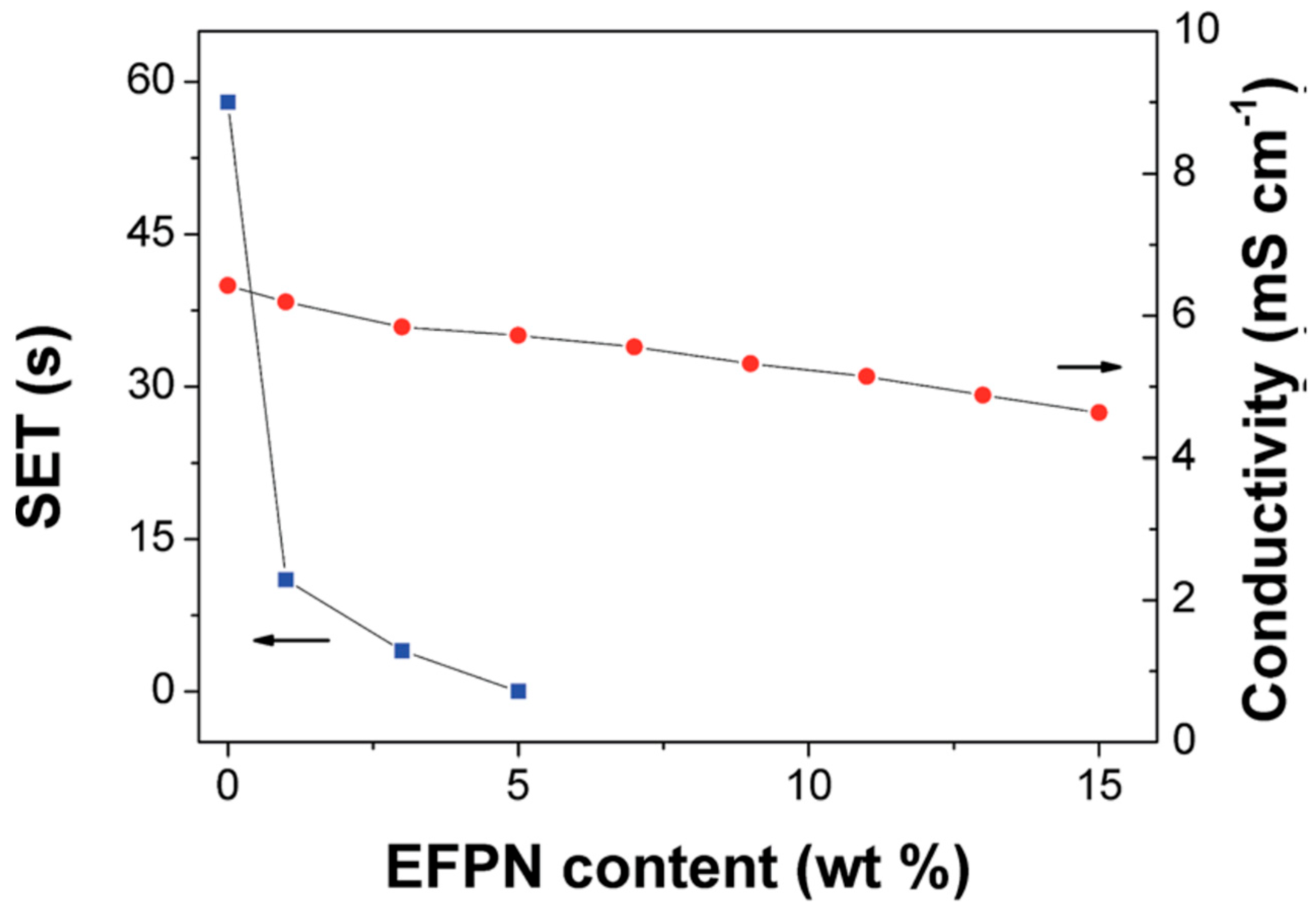
Careful selection of flame retarding additives also promotes overall cell safety. Feng et al [123] used ethoxy(pentafluoro)cyclotriphosphazene (EFPN) additive and investigated the flame-retarding efficiency with the base electrolyte, 1 M NaPF6 in EC:DEC solvent mixture. The resilience to flaming combustion hazard of the electrolyte was studied by so-called self-extinguishing time (SET). Figure 12 shows the variation in SET and ionic conductivity of the electrolyte with increasing EFPN content. The SET value dropped from 58 s to 0 s with no EFPN to 5 wt% of EFPN additive, hinting that the electrolyte transformed from ‘flammable’ to ‘non-flammable’ in these specific test conditions. The more global fire hazard need some more careful consideration however, since it will be assessed according to potential activation energy sources, which in the domain of batteries may rank well over ignition sources used to qualify flammability of liquid chemicals referring to the flash point measurements for regulatory purposes [124]. The ionic conductivity of the electrolyte decreased from 6.4 mS cm-1 to 5.7 mS cm-1 and then to 4.6 mS cm-1 when EFPN content increased from 0 to 5 wt% and to 15 wt%. Thus, it is also important to find an optimum between SET and conductivity. With 5% EFPN additive in the base electrolyte, the electrochemical performance of Na0.44MnO2 cathode and acetylene black anode improved as well.
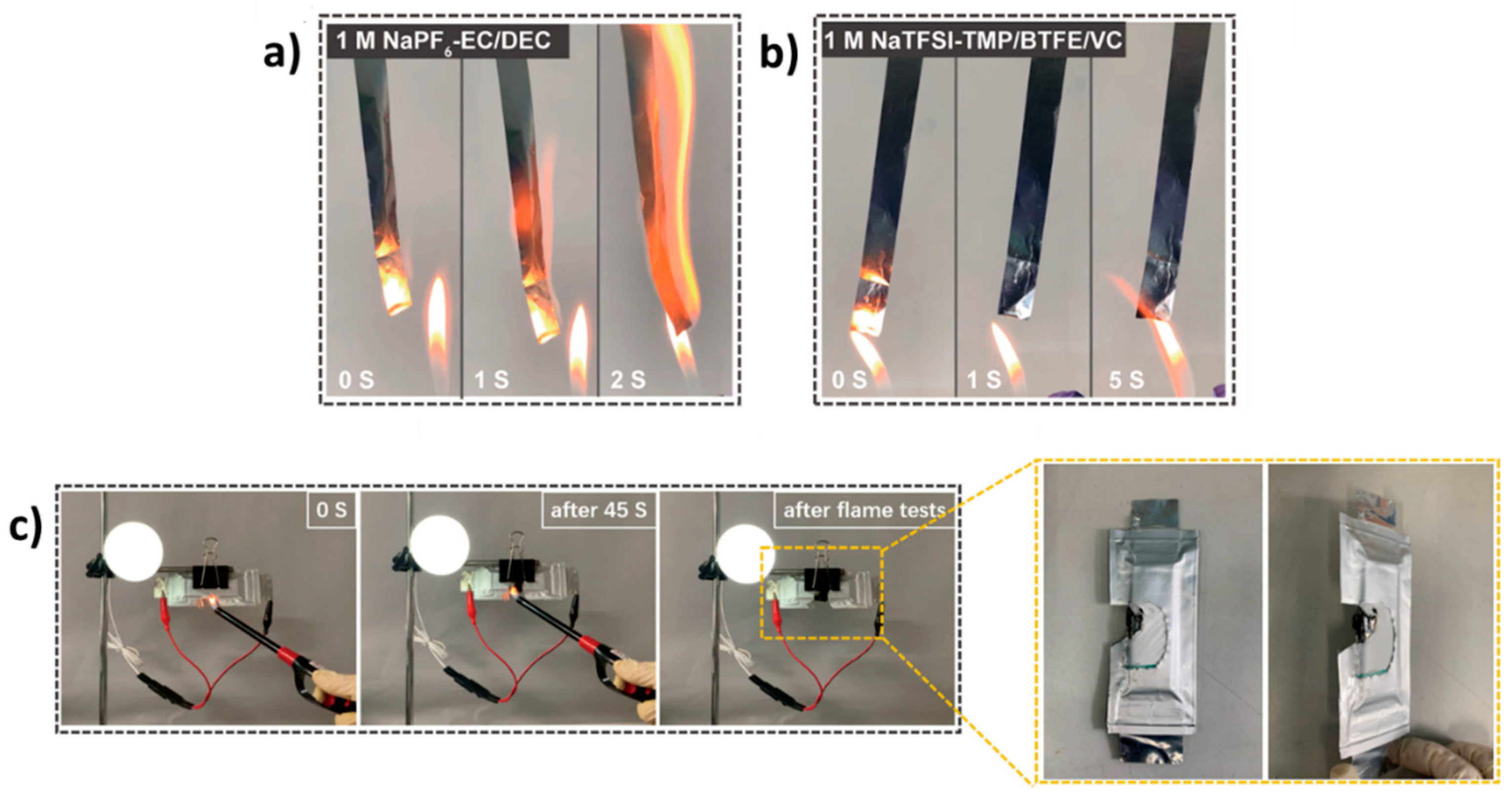
Yang et al [125] studied the effect of 1.2 M sodium bis(trifluoromethanesulfonyl) imide - trimethyl phosphate/bis(2,2,2-trifluoro ethyl) ether/vinylene carbonate electrolyte (1.2 M NaTFSI-TMP/BTFE/VC) with electrode contact to analyze the flammability behavior. It was compared to the classical electrolyte 1 M NaPF6 in EC/DEC which is flammable as shown in Figure 13a and possesses poor compatibility with electrodes due to continual electrolyte decomposition and poorer passivation film protection of electrodes. In comparison, 1.2 M NaTFSI-TMP/BTFE/VC shows improved resilience to flaming combustion (Figure 13b) due to the dispersed concentrated salt-solvent clusters by fluorinated BTFE ether. Hence, according to the fire test selected, it seemed to develop some fire-retardant properties with the proposed electrolyte. However, this kind of fire testing is not well recognized in the field of battery testing and ‘non-flammability’ claims (speaking about non-intrinsic material property) may be misleading in terms of real ignitability and combustibility. Next, pouch cells with sodium-vanadium phosphate || HC and prussian blue || HC were cycled with the fluorinated electrolyte and used to investigate the safety of the whole system using flame test by simultaneously powering a light bulb as shown in Figure 13c. The edge of the cell was cut and even though it was exposed to air, the bulb kept on glowing. As the cells burnt, no smoke or fire was emitted in these test conditions. The post-mortem results verified only the part that was in direct contact with flame was damaged, while the other parts remained intact. This was attributed due to the improved flame-retarding properties of the electrolyte. Thus, tuning electrolyte properties helps to produce safer sodium-ion batteries and such approaches must be promoted for advanced formulations.

4.2. Full Cell Level

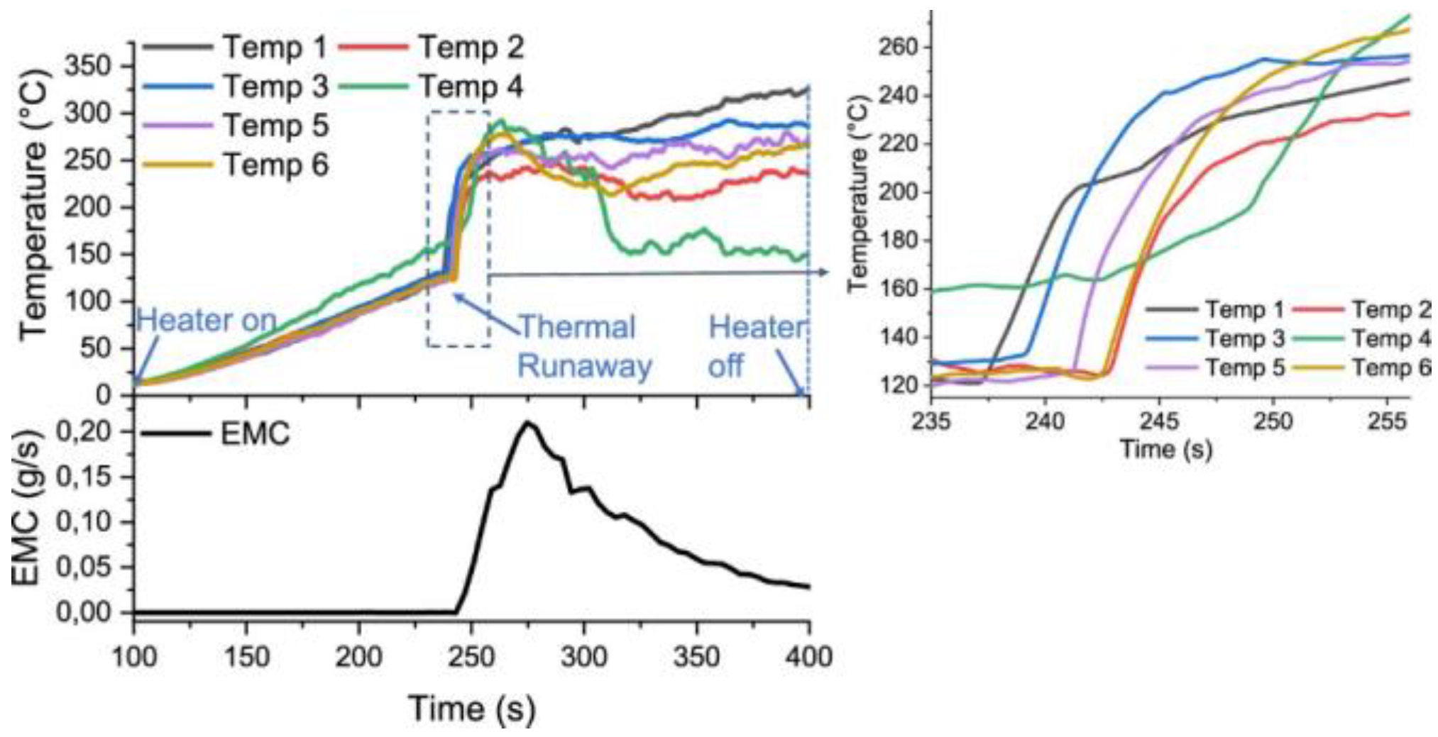
The French National Institute for Industrial Environment and Risks (INERIS) performed thermal runaway of 18650 type NVPF || HC cells commercialized by TIAMAT [126]. These Na-ion cells were charged to full SOC and then thermal runaway was triggered with homemade built system by overheating with four cartridge heaters (400 W each) integrated into copper block with calibrated holes. Six identical cylindrical cells were tested independently and as the heaters were switched on, the TR was observed when the temperature increased exponentially as shown in Figure 14. The time between the six cells that went into TR first (Temp 1) and in the end (Temp 4) was shorter than 15 seconds. The maximal average recorded temperature was 286 °C, with the degassing process from white fumes lasting no longer than 40 seconds. The gas analysis from these cells was simultaneously performed and the EMC solvent due to its volatile nature from electrolyte source showed the most abundant release during the same time of TR. The other released gases were PC, EC, H2, CO2, CO, CH4, C2H4 and HF. HF accounted to only 4 vol % of the total release which demonstrated limited toxicity originating from Na cells. Additionally, it showed no traces of POF3 toxic gas which is a common toxic hazard during LiBs thermal runaway.
To compare these results with those of LiB technology reported in the literature, the methods employed and the protocol analysis of TR must be consistent for fair differentiation. The comparable results for LiBs with non-flaming combustion were observed for the safer low nickel content layered oxide LiNi1-x-yMnxCoyO2 (NMC111 with x=y=0.33)||graphite and LiFePO4 (LFP)||graphite cell technologies when abused thermally by internal heater or overcharged [127,128]. The LFP and NVPF phosphate-based cathodes gave off mostly similar gases. However, PF3 gas was additionally observed in LFP cell abuse which was absent in NVPF chemistry. The NMC111 cells had some differences in gas generation from NVPF chemistry. The organic carbonates were present in lesser quantities in NMC111 cell but this was balanced by increasing amounts of CO2 and CO gases. This difference was due to the readiness of oxygen release in NMC cathode than NVPF and LFP chemistry.
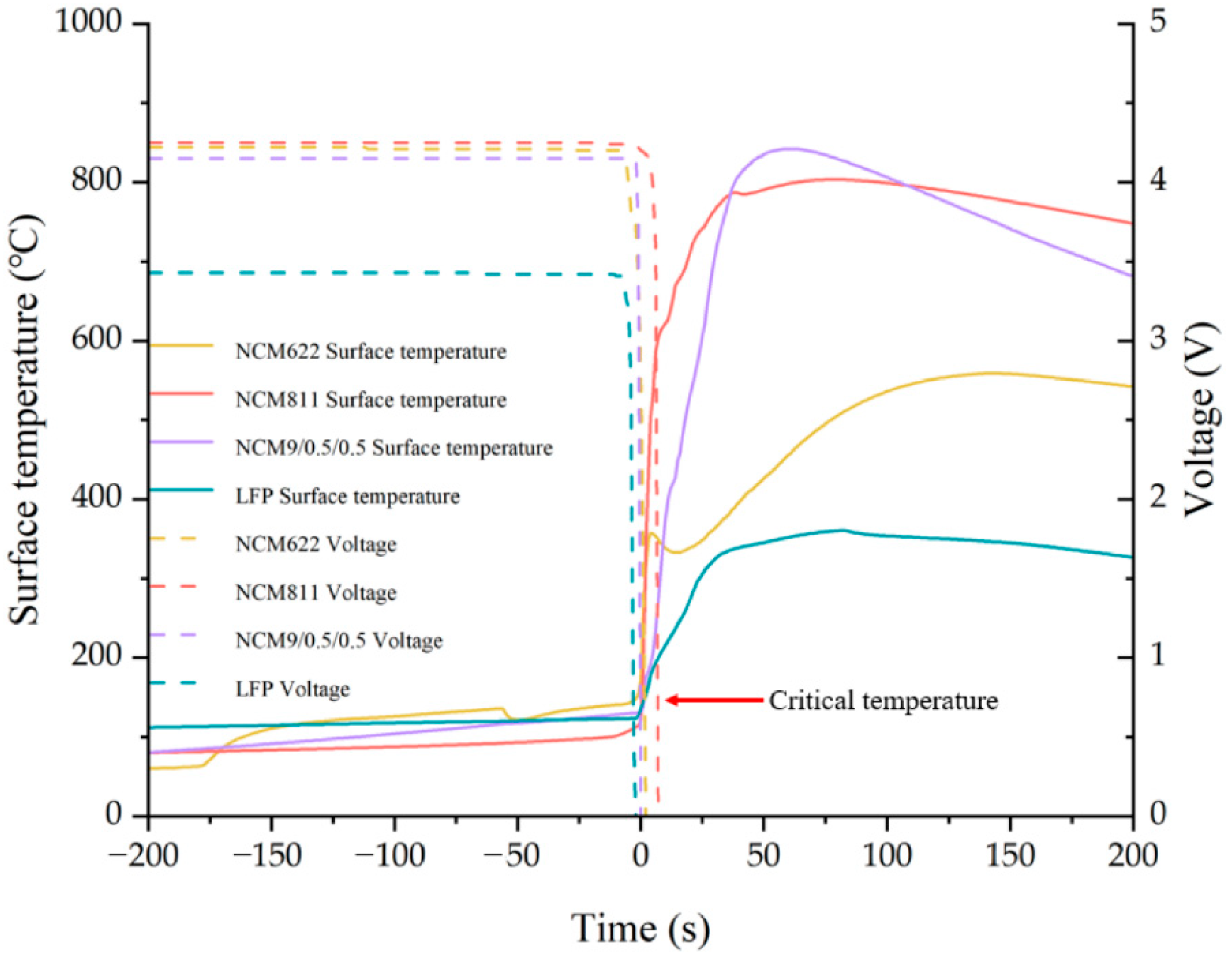
The work performed by Yang et al [129] for LiB cells who tested nickel-rich layered oxides LiNi1-x-yMnxCoyO2 (NMC622 with x=y=0.2, NMC811 with x=y=0.1, NMC9/0.5/0.5 with x=y=0.05) and LFP with graphite counter electrode brings some information for comparative purposes against NVPF-based SiB cells. Nickel-rich layered oxides inherently possess more energy density and oxygen release from these structures might induce increased safety concerns, however NVPF can be compared to LFP technology since both cathode materials have enhanced structural stability and common phosphate group. The experimental abuse test was performed in a sealed chamber equipped with pressure sensor in an inert atmosphere. The heating plate and the battery were placed side by side and TR was triggered by lateral heating. The temperature increased slowly and reached the critical temperature after which the battery temperature rose rapidly. The TR critical temperature obtained were 155 °C, 121 °C, 131 °C and 145 °C for NCM622, NCM811, NCM9/0.5/0.5 and LFP respectively. The more the delay in the critical temperature, the more enhanced is the battery safety. However, this critical temperature mostly depends on the processes taking place at the negative electrode (SEI breakdown followed by solvent reduction in contact with charged material) and thus is not impacted by the positive electrode material. The corresponding maximum thermal runaway temperature reached were 559 °C, 803 °C, 842 °C and 361 °C respectively as shown in Figure 15. The lower the maximum temperature of the battery, the less harmful is the overall battery state. Considering the maximal temperature that can be reached during TR, the LFP-based chemistry can be considered safer than Ni-rich NMC-based materials. The maximum temperature that can be reached for NMC-based materials increases due to higher energy density of the cell and higher propensity to release oxygen. Bugryniec et al [130] also compared the LFP cells against LCO chemistry under convection by overheating in an oven and found that LFP cells are more stable and showed less severe thermal behavior than LCO cells. For NVPF||HC-based cell as shown in Figure 14, it seems that the critical temperature failure also occurs around 125 °C, suggesting that processes on graphite and HC have the same impact on TR triggering. However, the NVPF||HC cell reaches lower maximal temperature than LFP||graphite cell (286 °C versus 361 °C from [126] and [129]) which might highlight its increased safety. Following this, the more interesting point of comparison would be the gases analysis during TR to compare the overall safe technology.
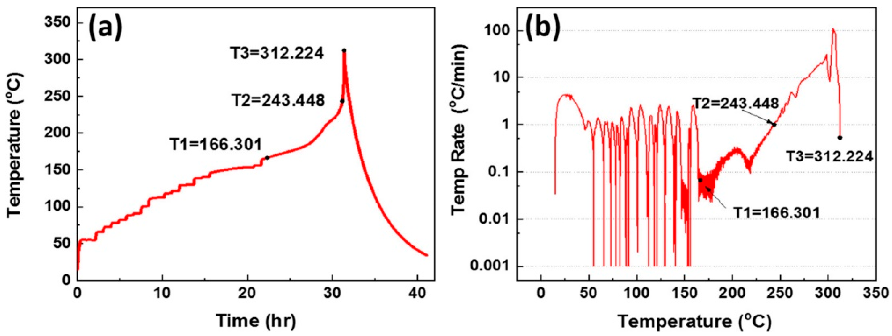
Xie et al [131] prepared sodium-pouch cell with layered oxide NaNi1/3Fe1/3Mn1/3O2 (NFM) cathode and HC anode and performed thermal runaway with Accelerating Rate Calorimetry (ARC). It was ramped at 5 K min-1 heating rate with heat-wait-seek protocol from 50 °C to approximately 300 °C [132]. Three distinct exothermal stages (Figure 16) were obtained, the first at 166 °C, where SEI decomposition and the internal short-circuit might have taken place, the other at 243 °C, where battery temperature increased exponentially and reached 1 °C min-1. The final temperature T3 was observed at 312 °C which was the peak maximal temperature. This temperature is significantly lower than that reached from most lithium-layered oxide cathode materials/graphite cells as for instance around 800 °C for NMC111 cathode as discussed above [129]. These results serve as a proof of concept of the lower maximal temperature for sodium layered cathode during TR as compared to lithium-ion counterparts [133,134].
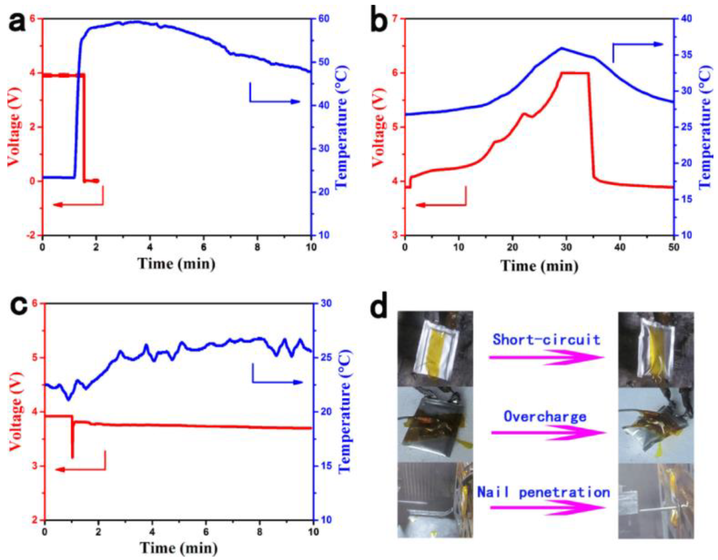
As potential alternative to non-graphitizable and disordered hard carbon structures, Li et al [135] employed pyrolyzed anthracite (PA) anode obtained in the 1000-1400 °C temperature range in SiBs. PA have an anisotropic structure which resembles to that of hard carbons between 1000 to 2000 °C with non-graphitizing carbons but can switch to high degree of graphitization above 2000 °C [136]. Pouch cells of O3-type layered oxide Na0.9[Cu0.22Fe0.30Mn0.48]O2 as cathode and PA as anode exhibiting energy density of 100 Wh kg-1 were fabricated. These pouch cells at 100% SOC were subjected to safety tests like external short circuit, overcharge and nail penetration tests, as shown in Figure 17. No smoke or fire were detected from these tests, however the cells swelled at the end of the overcharge test maybe because of high voltages reached outside the electrochemical stability window of the electrolyte inducing its oxidation leading to gas generation. However, the temperature increase was not of high magnitude for all safety tests. With the nail penetration test, the voltage returned to normal value once the nail was ejected from the system. These experiments also demonstrate the superior safety of SiBs system in these test conditions.
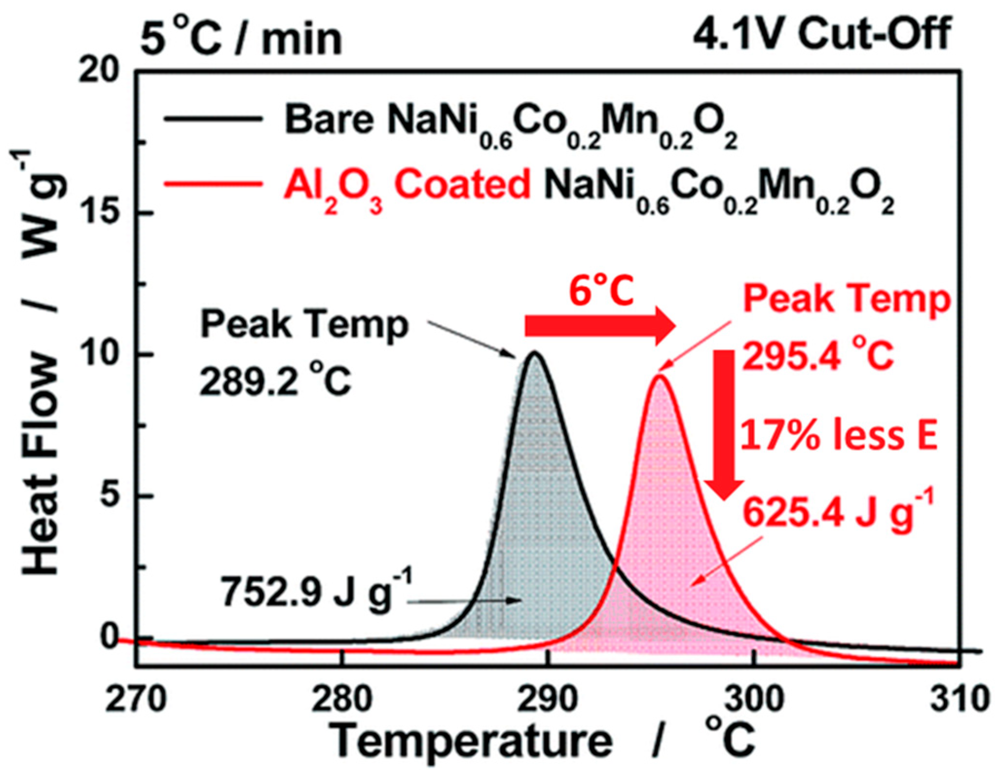
Hwang et al [137] studied pouch cells composed of bare or Al2O3 coated O3-type Na[Ni0.6Co0.2Mn0.2]O2 layered oxide cathode and HC anode. The cells were tested in the voltage range of 1.0 to 4.1 V. Al2O3 coated electrodes not only showed better coulombic efficiency but also showed an improvement in cycling performance. After charging, the cathode material was recovered from the current collector and DSC was performed at the scan rate of 5 °C min-1 to assess the thermal stability. The desodiated bare Na0.34[Ni0.6Co0.2Mn0.2]O2 shows an exothermic peak at 289 °C with heat generation of 753 J g-1. These results were significantly improved with Al2O3 coated desodiated material showing better thermal stability with a smaller exothermic peak occurring at 295 °C and decreased heat generation of 625 J g-1 as shown in Figure 18. The improved thermal stability was explained by uniform Al2O3 coating which prevents the oxidized cathode from being in direct contact with the electrolyte and delays oxygen release. These studies suggest that coating the active material is a good strategy not only to improve electrochemical performances but also overall cell safety.

5. Role of the Separator in Battery Safety

The separator has a major contribution in battery safety preventing short circuits and malfunction as it lies in the middle of cathode and anode to prevent physical contact between the two electrodes [138,139,140]. It also facilitates sodium or lithium ions transport while blocking electron flow and there exists a tradeoff between mechanical robustness for enhanced safety and ion transport properties [141]. The collapse of the separator by melting, shrinking or vaporizing under high temperature leads to thermal runaway [142]. During cell abuse, the mechanical collision might cause mismatch in separator alignment leading to contact with electroactive species or during overcharge the metal dendrites might penetrate the separator leading to short-circuit. Hence, the separator must have high heat resistance for battery application at elevated temperature, good mechanical properties to withstand resistance against unfortunate calamities, be inert in the electrochemical stability range to suppress side reactions and have high wettability compatibility with electrolyte to ensure effective ion migration and decrease in internal resistance [143].
Zhou et al [142] fabricated NMC532 and graphite Li-ion pouch cells with four different separators: cellulose-based, trilayer PP/PE/PP, standard propylene and homemade modified graphene-polydopamine coated separator. The latter is made of a PP separator soaked in polydopamine solution followed by slurry coating of carboxymethyl cellulose and graphene nanoflakes. The electrochemical formation cycles were done to form a uniform SEI layer and then the fully charged cells were subjected to ARC by employing heat-wait-seek method. The inhouse made separator showed the most improved thermal stability over the three commercial separators as evident from ARC experiment. This is suspected due to the enhanced mechanical robustness and anti-shrinkage properties under abusive conditions, such approaches using modified separators must be applied to SiB or LiB technology to maximize safety. Zu et al [144] developed polyolefin-based separators with reactive Mg(OH)2@MgO coatings to tackle lithium metal dendrite formation on lithium metal anode when cycled in liquid electrolyte. This protective coating interacts with lithium metal to eliminate lithium protuberance and facilitate uniform metal deposition. Such an approach can be extended to LiB and emerging SiB technologies to eliminate alkali metal dendritic plating while cycling at high current rates or low temperature and thus ensure added safety.
Conventional polyolefin (polyethylene or polypropylene) separators have poor wetting with SiB liquid electrolyte and low ionic conductivity in NaPF6 and NaClO4 based sodium salts [145,146]. Ho et al [145] introduced a poly(dopamine) modified PE separator by dip coating method, the dopamine incorporation in the PE separator increased the hydrophilicity of PE separator and promoted ionic conductivity. As a result, the electrochemical performance in HC half cells was improved as compared to bare PE separator. Kim et al [146] demonstrated that an SiO2 thin layer coated with Chemical Vapor Deposition (CVD) method onto a PE separator improved wettability with the electrolyte and ion transport properties. Therefore, the development of innovative coatings on polyolefin separators seems a great strategy to boost battery safety owing to the possibility of lowering internal resistance through wettability enhancement and avoiding short-circuits through elimination of alkali dendrite formation at the anode upon cycling and separator shrinkage upon thermal event.

6. Conclusion and Perspectives

Battery researchers often deal with the development and further improvement of high-energy or high-power cells with good cyclability. However, too often yet, the safety of the battery is not part of the primary focus. As frequent battery failures with large thermal runaways may cost hundreds of lives, battery safety must be accessed with equal priority. In this regard, this paper discusses the current understanding of safety issues pertaining to the emerging sodium-ion batteries. They possess advantages like reduced cost of production due to high sodium abundance, similar working principle and the possibility of using cheaper and lighter aluminum current collectors. The latter favors the over-discharge phenomenon promoting zero-volt storage and safer handling and shipping. Even though LiBs and SiBs function with a similar charge-discharge phenomenon, the same pre-established set of rules with analogous corresponding cathode or electrolyte will not function prominently. It is a system that needs to be optimized differently to maintain stable interfaces with electrolyte engineering. Indeed, the SEI in SiBs is generally reported to be more vulnerable than in LiBs. Here, we talk about how the electrolyte optimization aids to mitigate this issue and delay SEI breakdown at the origin of the thermal runaway triggering. As with LiBs, identifying additives with a synergistic effect that is truly exceptional remains a significant challenge. This paper also compares most of the electrode materials commonly used in SiBs and LiBs. The studied desodiated layered oxides showed better thermal stability. However, further layered oxide materials and proofs of the exothermic thermal decomposition paths in presence or not of the electrolyte still requires in-depth investigations to generalize on the better thermal stability of this cathode family. These studies can benefit from the latest cutting-edge operando technologies. As example, real-time in-situ TEM studies taught a lesson to find an optimum between cycling to higher voltages to extract the maximum capacity and maintaining the cathode structure upon heating, focusing on safety. However, some sodium-ion cells, NVPF||HC or O3-type layered oxide Na0.9[Cu0.22Fe0.30Mn0.48]O2||pyrolyzed anthracite, showed no flaming combustion during thermal abuse tests or when exposed to external short circuits, overcharge tests or nail penetration tests, respectively encouraging companies like Tiamat in France and Faradion in the UK to turn the pages of proposed future SiBs from research papers to the physical batteries of today. With great inventions come even greater responsibilities, hence, one must access great depths into the safety of such latest technologies. As in the case of Li-ion, Na-ion is not based on one unique chemistry, and therefore, any new variant of Na-ion needs to be reassessed and relating safety profile must be examined. Furthermore, its threats should be benchmarked with potential alternatives before any choice for a given application.

Supplementary Materials

The following supporting information can be downloaded at the website of this paper posted on Preprints.org.

Author Contributions

Conceptualization, G.M.; Validation, S.G., A.E.M., S.L. and G.M.; Investigation, P.T.B.; Writing - Original Draft Preparation, P.T.B.; Writing - Review & Editing, S.G. and G.M.; Visualization, P.T;B.; Supervision, S.L. and G.M. All authors have read and agreed to the published version of the manuscript.

Funding

As a part of the DESTINY Ph.D. program, this publication is acknowledged by funding from the European Union's Horizon2020 research and innovation program under the Marie Skłodowska-Curie Actions COFUND (Grant Agreement #945357).

Data Availability Statement

No new data were created in this study. Data sharing is not applicable to this article.

Conflicts of Interest

The authors declare no conflict of interest.

References

  1. Luo, X.; Wang, J.; Dooner, M.; Clarke, J. Overview of Current Development in Electrical Energy Storage Technologies and the Application Potential in Power System Operation. Applied Energy 2015, 137, 511–536. [Google Scholar] [CrossRef]
  2. Mitali, J.; Dhinakaran, S.; Mohamad, A.A. Energy Storage Systems: A Review. Energy Storage and Saving 2022, 1, 166–216. [Google Scholar] [CrossRef]
  3. Kurzweil, P. Gaston Planté and His Invention of the Lead–Acid Battery—The Genesis of the First Practical Rechargeable Battery. Journal of Power Sources 2010, 195, 4424–4434. [Google Scholar] [CrossRef]
  4. Zhu, X.; Li, L.; Sun, X.; Yang, D.; Gao, L.; Liu, J.; Kumar, R.V.; Yang, J. Preparation of Basic Lead Oxide from Spent Lead Acid Battery Paste via Chemical Conversion. Hydrometallurgy 2012, 117–118, 24–31. [Google Scholar] [CrossRef]
  5. Zhang, J.; Chen, C.; Zhang, X.; Liu, S. Study on the Environmental Risk Assessment of Lead-Acid Batteries. Procedia Environmental Sciences 2016, 31, 873–879. [Google Scholar] [CrossRef]
  6. World Health Organization, Recycling Used Lead-Acid Batteries: Health Considerations; World Health Organization: Geneva, 2017; ISBN 978-92-4-151285-5.
  7. Bernard, P. SECONDARY BATTERIES – NICKEL SYSTEMS | Nickel–Cadmium: Sealed. In Encyclopedia of Electrochemical Power Sources; Elsevier, 2009; pp. 459–481 ISBN 978-0-444-52745-5.
  8. EU Bans Nickel-Cadmium Batteries in Portable Devices by 2025: Impact on Emergency Lighting. Available online: https://www.etaplighting.com/en/blog/end-of-cadmium-batteries-portable-applications (accessed on 16 April 2024).
  9. Maxianova, K.; Rusche, T.M. Restriction of Hazardous Substances: On the Need for and the Limits of Comitology. Rev EC Int Env Law 2006, 15, 202–210. [Google Scholar] [CrossRef]
  10. Bernard, P.; Lippert, M. Nickel–Cadmium and Nickel–Metal Hydride Battery Energy Storage. In Electrochemical Energy Storage for Renewable Sources and Grid Balancing; Elsevier, 2015; pp. 223–251 ISBN 978-0-444-62616-5.
  11. Ikoma, M.; Yuasa, S.; Yuasa, K.; Kaida, S.; Matsumoto, I.; Iwakura, C. Charge Characteristics of Sealed-Type Nickel/Metal-Hydride Battery. Journal of Alloys and Compounds 1998, 267, 252–256. [Google Scholar] [CrossRef]
  12. Winn, D.A.; Shemilt, J.M.; Steele, B.C.H. Titanium Disulphide: A Solid Solution Electrode for Sodium and Lithium. Materials Research Bulletin 1976, 11, 559–566. [Google Scholar] [CrossRef]
  13. Whittingham, M.S. Electrical Energy Storage and Intercalation Chemistry. Science 1976, 192, 1126–1127. [Google Scholar] [CrossRef]
  14. Cairns, E.J.; Shimotake, H. High-Temperature Batteries: Research in High-Temperature Electrochemistry Reveals Compact, Powerful Energy-Storage Cells. Science 1969, 164, 1347–1355. [Google Scholar] [CrossRef]
  15. Nishi, Y. Lithium Ion Secondary Batteries; Past 10 Years and the Future. Journal of Power Sources 2001, 100, 101–106. [Google Scholar] [CrossRef]
  16. Feng, X.; Ouyang, M.; Liu, X.; Lu, L.; Xia, Y.; He, X. Thermal Runaway Mechanism of Lithium Ion Battery for Electric Vehicles: A Review. Energy Storage Materials 2018, 10, 246–267. [Google Scholar] [CrossRef]
  17. Lyu, Y.; Wu, X.; Wang, K.; Feng, Z.; Cheng, T.; Liu, Y.; Wang, M.; Chen, R.; Xu, L.; Zhou, J.; et al. An Overview on the Advances of LiCoO 2 Cathodes for Lithium-Ion Batteries. Advanced Energy Materials 2021, 11, 2000982. [Google Scholar] [CrossRef]
  18. Cho, J.; Kim, Y.J.; Park, B. Novel LiCoO 2 Cathode Material with Al 2 O 3 Coating for a Li Ion Cell. Chem. Mater. 2000, 12, 3788–3791. [Google Scholar] [CrossRef]
  19. Jo, M.; Hong, Y.-S.; Choo, J.; Cho, J. Effect of LiCoO[Sub 2] Cathode Nanoparticle Size on High Rate Performance for Li-Ion Batteries. J. Electrochem. Soc. 2009, 156, A430. [Google Scholar] [CrossRef]
  20. Ahangari, M.; Szalai, B.; Lujan, J.; Zhou, M.; Luo, H. Advancements and Challenges in High-Capacity Ni-Rich Cathode Materials for Lithium-Ion Batteries. Materials 2024, 17, 801. [Google Scholar] [CrossRef] [PubMed]
  21. Xia, Y.; Zheng, J.; Wang, C.; Gu, M. Designing Principle for Ni-Rich Cathode Materials with High Energy Density for Practical Applications. Nano Energy 2018, 49, 434–452. [Google Scholar] [CrossRef]
  22. Zhang, S.S. Problems and Their Origins of Ni-Rich Layered Oxide Cathode Materials. Energy Storage Materials 2020, 24, 247–254. [Google Scholar] [CrossRef]
  23. Chakraborty, A.; Kunnikuruvan, S.; Kumar, S.; Markovsky, B.; Aurbach, D.; Dixit, M.; Major, D.T. Layered Cathode Materials for Lithium-Ion Batteries: Review of Computational Studies on LiNi 1– xy Co x Mn y O 2 and LiNi 1– xy Co x Al y O 2. Chem. Mater. 2020, 32, 915–952. [Google Scholar] [CrossRef]
  24. Vitins, G.; West, K. Lithium Intercalation into Layered LiMnO2. J. Electrochem. Soc. 1997, 144, 2587–2592. [Google Scholar] [CrossRef]
  25. Berg, H.; Göransson, K.; Noläng, B.; Thomas, J.O. Electronic Structure and Stability of the LixMn2O4 (0 < x < 2) System. J. Mater. Chem. 1999, 9, 2813–2820. [Google Scholar] [CrossRef]
  26. Cheruku, R.; Kruthika, G.; Govindaraj, G.; Vijayan, L. Electrical Relaxation Studies of Olivine Type Nanocrystalline LiMPO4 (M=Ni, Mn and Co) Materials. Journal of Physics and Chemistry of Solids 2015, 86, 27–35. [Google Scholar] [CrossRef]
  27. Manthiram, A. A Reflection on Lithium-Ion Battery Cathode Chemistry. Nat Commun 2020, 11, 1550. [Google Scholar] [CrossRef] [PubMed]
  28. Benoit, C.; Franger, S. Chemistry and Electrochemistry of Lithium Iron Phosphate. J Solid State Electrochem 2008, 12, 987–993. [Google Scholar] [CrossRef]
  29. Dahn, J.; Fuller, E.; Obrovac, M.; Vonsacken, U. Thermal Stability of LixCoO2, LixNiO2 and λ-MnO2 and Consequences for the Safety of Li-Ion Cells. Solid State Ionics 1994, 69, 265–270. [Google Scholar] [CrossRef]
  30. Bak, S.-M.; Hu, E.; Zhou, Y.; Yu, X.; Senanayake, S.D.; Cho, S.-J.; Kim, K.-B.; Chung, K.Y.; Yang, X.-Q.; Nam, K.-W. Structural Changes and Thermal Stability of Charged LiNi x Mn y Co z O 2 Cathode Materials Studied by Combined In Situ Time-Resolved XRD and Mass Spectroscopy. ACS Appl. Mater. Interfaces 2014, 6, 22594–22601. [Google Scholar] [CrossRef] [PubMed]
  31. Rumble, C.; Conry, T.E.; Doeff, M.; Cairns, E.J.; Penner-Hahn, J.E.; Deb, A. Structural and Electrochemical Investigation of Li(Ni[Sub 0.4]Co[Sub 0.15]Al[Sub 0.05]Mn[Sub 0.4])O[Sub 2] Cathode Material. J. Electrochem. Soc. 2010, 157, A1317. [Google Scholar] [CrossRef]
  32. Wang, J.; Li, Y.; Liu, R.; Xu, X.-M.; Zeng, C.-S.; Shen, X.-B.; Gu, Y.-J. The Different Roles of Ni2+/Ni3+, Ni3+/Ni4+, and Mn3+/Mn4+ in Li-Rich Layered Nanostructured LiNi Mn1-O2·Li2MnO3 with High Capacity. International Journal of Electrochemical Science 2021, 16, 210425. [Google Scholar] [CrossRef]
  33. Schafzahl, L.; Mahne, N.; Schafzahl, B.; Wilkening, M.; Slugovc, C.; Borisov, S.M.; Freunberger, S.A. Singlet Oxygen during Cycling of the Aprotic Sodium-O2 Battery. Angew Chem Int Ed Engl 2017, 56, 15728–15732. [Google Scholar] [CrossRef]
  34. Kalyani, P.; Kalaiselvi, N. Various Aspects of LiNiO 2 Chemistry: A Review. Science and Technology of Advanced Materials 2005, 6, 689–703. [Google Scholar] [CrossRef]
  35. Salomez, B.; Grugeon, S.; Armand, M.; Tran-Van, P.; Laruelle, S. Review—Gassing Mechanisms in Lithium-Ion Battery. J. Electrochem. Soc. 2023, 170, 050537. [Google Scholar] [CrossRef]
  36. Electrochemical Devices for Energy Storage Applications; Kebede, M.A., Ezema, F.I., Eds.; 1st ed.; CRC Press, 2019; ISBN 978-0-367-85511-6.
  37. Mao, N.; Gadkari, S.; Wang, Z.; Zhang, T.; Bai, J.; Cai, Q. A Comparative Analysis of Lithium-Ion Batteries with Different Cathodes under Overheating and Nail Penetration Conditions. Energy 2023, 278, 128027. [Google Scholar] [CrossRef]
  38. Brand, M.; Gläser, S.; Geder, J.; Menacher, S.; Obpacher, S.; Jossen, A.; Quinger, D. Electrical Safety of Commercial Li-Ion Cells Based on NMC and NCA Technology Compared to LFP Technology. WEVJ 2013, 6, 572–580. [Google Scholar] [CrossRef]
  39. Bugryniec, P.J.; Resendiz, E.G.; Nwophoke, S.M.; Khanna, S.; James, C.; Brown, S.F. Review of Gas Emissions from Lithium-Ion Battery Thermal Runaway Failure — Considering Toxic and Flammable Compounds. Journal of Energy Storage 2024, 87, 111288. [Google Scholar] [CrossRef]
  40. Azuma, H.; Imoto, H.; Yamada, S.; Sekai, K. Advanced Carbon Anode Materials for Lithium Ion Cells. Journal of Power Sources 1999, 81–82, 1–7. [Google Scholar] [CrossRef]
  41. Asenbauer, J.; Eisenmann, T.; Kuenzel, M.; Kazzazi, A.; Chen, Z.; Bresser, D. The Success Story of Graphite as a Lithium-Ion Anode Material – Fundamentals, Remaining Challenges, and Recent Developments Including Silicon (Oxide) Composites. Sustainable Energy Fuels 2020, 4, 5387–5416. [Google Scholar] [CrossRef]
  42. Li, L.; Zhang, D.; Deng, J.; Gou, Y.; Fang, J.; Cui, H.; Zhao, Y.; Cao, M. Carbon-Based Materials for Fast Charging Lithium-Ion Batteries. Carbon 2021, 183, 721–734. [Google Scholar] [CrossRef]
  43. Yoon, T.; Milien, M.S.; Parimalam, B.S.; Lucht, B.L. Thermal Decomposition of the Solid Electrolyte Interphase (SEI) on Silicon Electrodes for Lithium Ion Batteries. Chem. Mater. 2017, 29, 3237–3245. [Google Scholar] [CrossRef]
  44. Sick, N.; Krätzig, O.; Eshetu, G.G.; Figgemeier, E. A Review of the Publication and Patent Landscape of Anode Materials for Lithium Ion Batteries. Journal of Energy Storage 2021, 43, 103231. [Google Scholar] [CrossRef]
  45. Yan, H.; Zhang, D.; Qilu, *!!! REPLACE !!!*; Duo, X.; Sheng, X. A Review of Spinel Lithium Titanate (Li4Ti5O12) as Electrode Material for Advanced Energy Storage Devices. Ceramics International 2021, 47, 5870–5895. [Google Scholar] [CrossRef]
  46. Belharouak, I.; Koenig, G.M.; Amine, K. Electrochemistry and Safety of Li4Ti5O12 and Graphite Anodes Paired with LiMn2O4 for Hybrid Electric Vehicle Li-Ion Battery Applications. Journal of Power Sources 2011, 196, 10344–10350. [Google Scholar] [CrossRef]
  47. Desai, P.; Forero-Saboya, J.; Meunier, V.; Rousse, G.; Deschamps, M.; Abakumov, A.M.; Tarascon, J.-M.; Mariyappan, S. Mastering the Synergy between Na3V2(PO4)2F3 Electrode and Electrolyte: A Must for Na-Ion Cells. Energy Storage Materials 2023, 57, 102–117. [Google Scholar] [CrossRef]
  48. Tournevis sans Fil DEXTER Sodium 3.6 V 0.7 Ah | Leroy Merlin. Available online: https://www.leroymerlin.fr/produits/outillage/outillage-electroportatif/visseuse-et-tournevis-electrique/visseuse/tournevis-sans-fil-dexter-sodium-3-6-v-0-7-ah-86650845.html (accessed on 8 July 2024).
  49. Barker, J.; Heap, R.J.; Roche, N.; Tan, C.; Sayers, R.; Whitley, J.; Liu, Y. High Energy Density Na-Ion Battery Technology. Meet. Abstr. 2016; MA2016-03, 796–796. [Google Scholar] [CrossRef]
  50. Faradion Transport Applications. Available online: https://faradion.co.uk/applications/transport-applications/ (accessed on 14 June 2023).
  51. Gupta, Y.; Siwatch, P.; Karwasra, R.; Sharma, K.; Tripathi, S.K. Recent Progress of Layered Structured P2- and O3- Type Transition Metal Oxides as Cathode Material for Sodium-Ion Batteries. Renewable and Sustainable Energy Reviews 2024, 192, 114167. [Google Scholar] [CrossRef]
  52. Wang, P.-F.; You, Y.; Yin, Y.-X.; Guo, Y.-G. Layered Oxide Cathodes for Sodium-Ion Batteries: Phase Transition, Air Stability, and Performance. Adv. Energy Mater. 2018, 8, 1701912. [Google Scholar] [CrossRef]
  53. Grépin, E.; Jacquet, Q.; Moiseev, I.A.; Iadecola, A.; Rousse, G.; Avdeev, M.; Abakumov, A.M.; Tarascon, J.-M.; Mariyappan, S. Mastering the Synthesis of High Na-Content, Moisture-Stable Layered Oxide Cathode for Na-Ion Batteries. Journal of Power Sources 2024, 613, 234962. [Google Scholar] [CrossRef]
  54. Huang, Y.; Zeng, W.; Li, K.; Zhu, X. Na-Deficient P2-Type Layered Oxide Cathodes for Practical Sodium-Ion Batteries. Microstructures 2024, 4. [Google Scholar] [CrossRef]
  55. Ni, Q.; Bai, Y.; Wu, F.; Wu, C. Polyanion-Type Electrode Materials for Sodium-Ion Batteries. Adv. Sci. 2017, 4, 1600275. [Google Scholar] [CrossRef]
  56. Xu, C.; Zhao, J.; Yang, C.; Hu, Y.-S. Polyanionic Cathode Materials for Practical Na-Ion Batteries toward High Energy Density and Long Cycle Life. ACS Cent. Sci. 2023, 9, 1721–1736. [Google Scholar] [CrossRef] [PubMed]
  57. Li, H.; Xu, M.; Zhang, Z.; Lai, Y.; Ma, J. Engineering of Polyanion Type Cathode Materials for Sodium-Ion Batteries: Toward Higher Energy/Power Density. Adv Funct Materials 2020, 30, 2000473. [Google Scholar] [CrossRef]
  58. Lv, Z.; Ling, M.; Yue, M.; Li, X.; Song, M.; Zheng, Q.; Zhang, H. Vanadium-Based Polyanionic Compounds as Cathode Materials for Sodium-Ion Batteries: Toward High-Energy and High-Power Applications. Journal of Energy Chemistry 2021, 55, 361–390. [Google Scholar] [CrossRef]
  59. He, M.; Davis, R.; Chartouni, D.; Johnson, M.; Abplanalp, M.; Troendle, P.; Suetterlin, R.-P. Assessment of the First Commercial Prussian Blue Based Sodium-Ion Battery. Journal of Power Sources 2022, 548, 232036. [Google Scholar] [CrossRef]
  60. Sodium-Ion Batteries & Sustainable Energy | Natron Energy. Available online: https://natron.energy/ (accessed on 8 July 2024).
  61. Bie, X.; Kubota, K.; Hosaka, T.; Chihara, K.; Komaba, S. Synthesis and Electrochemical Properties of Na-Rich Prussian Blue Analogues Containing Mn, Fe, Co, and Fe for Na-Ion Batteries. Journal of Power Sources 2018, 378, 322–330. [Google Scholar] [CrossRef]
  62. Han, J.; Lin, Y.; Yang, Y.; Zuo, D.; Wang, C.; Liu, X. Dominant Role of M Element on the Stability and Properties of Prussian Blue Analogues NaxMFe(CN)6 (M = 3d Transition Metal) as Cathode Material for the Sodium-Ion Batteries. Journal of Alloys and Compounds 2021, 870, 159533. [Google Scholar] [CrossRef]
  63. Ojwang, D.O.; Häggström, L.; Ericsson, T.; Ångström, J.; Brant, W.R. Influence of Sodium Content on the Thermal Behavior of Low Vacancy Prussian White Cathode Material. Dalton Trans. 2020, 49, 3570–3579. [Google Scholar] [CrossRef] [PubMed]
  64. Xiao, Y.; Xiao, J.; Zhao, H.; Li, J.; Zhang, G.; Zhang, D.; Guo, X.; Gao, H.; Wang, Y.; Chen, J.; et al. Prussian Blue Analogues for Sodium-Ion Battery Cathodes: A Review of Mechanistic Insights, Current Challenges, and Future Pathways. Small 2024, 2401957. [Google Scholar] [CrossRef]
  65. Perveen, T.; Siddiq, M.; Shahzad, N.; Ihsan, R.; Ahmad, A.; Shahzad, M.I. Prospects in Anode Materials for Sodium Ion Batteries - A Review. Renewable and Sustainable Energy Reviews 2020, 119, 109549. [Google Scholar] [CrossRef]
  66. Dou, X.; Hasa, I.; Saurel, D.; Vaalma, C.; Wu, L.; Buchholz, D.; Bresser, D.; Komaba, S.; Passerini, S. Hard Carbons for Sodium-Ion Batteries: Structure, Analysis, Sustainability, and Electrochemistry. Materials Today 2019, 23, 87–104. [Google Scholar] [CrossRef]
  67. Yan, C.; Yuan, H.; Park, H.S.; Huang, J.-Q. Perspective on the Critical Role of Interface for Advanced Batteries. Journal of Energy Chemistry 2020, 47, 217–220. [Google Scholar] [CrossRef]
  68. Winter, M. The Solid Electrolyte Interphase – The Most Important and the Least Understood Solid Electrolyte in Rechargeable Li Batteries. Zeitschrift für Physikalische Chemie 2009, 223, 1395–1406. [Google Scholar] [CrossRef]
  69. Wang, H.; Li, X.; Li, F.; Liu, X.; Yang, S.; Ma, J. Formation and Modification of Cathode Electrolyte Interphase: A Mini Review. Electrochemistry Communications 2021, 122, 106870. [Google Scholar] [CrossRef]
  70. Eshetu, G.G.; Diemant, T.; Hekmatfar, M.; Grugeon, S.; Behm, R.J.; Laruelle, S.; Armand, M.; Passerini, S. Impact of the Electrolyte Salt Anion on the Solid Electrolyte Interphase Formation in Sodium Ion Batteries. Nano Energy 2019, 55, 327–340. [Google Scholar] [CrossRef]
  71. Ma, L.A.; Naylor, A.J.; Nyholm, L.; Younesi, R. Strategies for Mitigating Dissolution of Solid Electrolyte Interphases in Sodium-Ion Batteries. Angew. Chem. Int. Ed. 2021, 60, 4855–4863. [Google Scholar] [CrossRef] [PubMed]
  72. Mogensen, R.; Brandell, D.; Younesi, R. Solubility of the Solid Electrolyte Interphase (SEI) in Sodium Ion Batteries. ACS Energy Lett. 2016, 1, 1173–1178. [Google Scholar] [CrossRef]
  73. Eshetu, G.G.; Grugeon, S.; Kim, H.; Jeong, S.; Wu, L.; Gachot, G.; Laruelle, S.; Armand, M.; Passerini, S. Comprehensive Insights into the Reactivity of Electrolytes Based on Sodium Ions. ChemSusChem 2016, 9, 462–471. [Google Scholar] [CrossRef] [PubMed]
  74. Liaw, H.-J.; Liou, Y.-R.; Liu, P.-H.; Chen, H.-Y.; Shu, C.-M. Increased Flammability Hazard When Ionic Liquid [C6mim][Cl] Is Exposed to High Temperatures. Journal of Hazardous Materials 2019, 367, 407–417. [Google Scholar] [CrossRef] [PubMed]
  75. 01 - Home | EV Fire Safe. Available online: https://www.evfiresafe.com/ (accessed on 22 April 2024).
  76. EPRI BESS Failure Incident Database. Available online: https://storagewiki.epri.com/index.php/BESS_Failure_Incident_Database (accessed on 29 July 2024).
  77. Marlair Guy; Lecocq Amandine; Bordes Arnaud; Christensen Paul; Truchot Benjamin Key Learnings From Recent Lithium-Ion Battery Incidents That Have Impacted e-Mobility and Energy Storage Fast Growing Markets. Chemical Engineering Transactions 2022, 90, 643–648. [CrossRef]
  78. CALCE and the University of Maryland Safety. Available online: https://web.calce.umd.edu/batteries/safety.html (accessed on 20 September 2023).
  79. Park Taejon Renault-Samsung’s Electric Vehicle Catches Fire Due to Ignition from Bonnet. Available online: https://english.etnews.com/20160127200001 (accessed on 20 September 2023).
  80. CTIF International Association of Fire and Rescue Services Large Explosion and Fire at French Lithium Battery Warehouse. Available online: https://ctif.org/news/large-explosion-and-fire-french-lithium-battery-warehouse (accessed on 20 September 2023).
  81. South Korea: Exploding Lithium Batteries Spark Deadly Factory Fire. Available online: https://www.bbc.com/news/articles/crgggmeyjj7o (accessed on 9 July 2024).
  82. DESTINY PhD Programme Marie Skłodowska-Curie Actions COFUND. Available online: https://www.destiny-phd.eu/topic-22---2 (accessed on 22 April 2024).
  83. Regulation - 2023/1542 - EN - EUR-Lex. Available online: https://eur-lex.europa.eu/eli/reg/2023/1542/oj (accessed on 22 April 2024).
  84. Official Journal of the European Union REGULATION (EU) 2023/1542 OF THE EUROPEAN PARLIAMENT AND OF THE COUNCIL of 12 July 2023 Concerning Batteries and Waste Batteries, Amending Directive 2008/98/EC and Regulation (EU) 2019/1020 and Repealing Directive 2006/66/EC.
  85. Patil, A.; Patil, V.; Wook Shin, D.; Choi, J.-W.; Paik, D.-S.; Yoon, S.-J. Issue and Challenges Facing Rechargeable Thin Film Lithium Batteries. Materials Research Bulletin 2008, 43, 1913–1942. [Google Scholar] [CrossRef]
  86. Cheng, X.-B.; Zhang, R.; Zhao, C.-Z.; Wei, F.; Zhang, J.-G.; Zhang, Q. A Review of Solid Electrolyte Interphases on Lithium Metal Anode. Adv. Sci. 2016, 3, 1500213. [Google Scholar] [CrossRef]
  87. An, S.J.; Li, J.; Daniel, C.; Mohanty, D.; Nagpure, S.; Wood, D.L. The State of Understanding of the Lithium-Ion-Battery Graphite Solid Electrolyte Interphase (SEI) and Its Relationship to Formation Cycling. Carbon 2016, 105, 52–76. [Google Scholar] [CrossRef]
  88. Hausbrand, R. Electronic Energy Levels at Li-Ion Cathode–Liquid Electrolyte Interfaces: Concepts, Experimental Insights, and Perspectives. The Journal of Chemical Physics 2020, 152, 180902. [Google Scholar] [CrossRef]
  89. Abe, K.; Yoshitake, H.; Kitakura, T.; Hattori, T.; Wang, H.; Yoshio, M. Additives-Containing Functional Electrolytes for Suppressing Electrolyte Decomposition in Lithium-Ion Batteries. Electrochimica Acta 2004, 49, 4613–4622. [Google Scholar] [CrossRef]
  90. Cometto, C.; Yan, G.; Mariyappan, S.; Tarascon, J.-M. Means of Using Cyclic Voltammetry to Rapidly Design a Stable DMC-Based Electrolyte for Na-Ion Batteries. J. Electrochem. Soc. 2019, 166, A3723–A3730. [Google Scholar] [CrossRef]
  91. Zhang, L.; Tsolakidou, C.; Mariyappan, S.; Tarascon, J.-M.; Trabesinger, S. Unraveling Gas Evolution in Sodium Batteries by Online Electrochemical Mass Spectrometry. Energy Storage Materials 2021, 42, 12–21. [Google Scholar] [CrossRef]
  92. Yan, G.; Reeves, K.; Foix, D.; Li, Z.; Cometto, C.; Mariyappan, S.; Salanne, M.; Tarascon, J. A New Electrolyte Formulation for Securing High Temperature Cycling and Storage Performances of Na-Ion Batteries. Adv. Energy Mater. 2019, 9, 1901431. [Google Scholar] [CrossRef]
  93. Tran, M.-K.; Mevawalla, A.; Aziz, A.; Panchal, S.; Xie, Y.; Fowler, M. A Review of Lithium-Ion Battery Thermal Runaway Modeling and Diagnosis Approaches. Processes 2022, 10, 1192. [Google Scholar] [CrossRef]
  94. Forestier, C.; Grugeon, S.; Davoisne, C.; Lecocq, A.; Marlair, G.; Armand, M.; Sannier, L.; Laruelle, S. Graphite Electrode Thermal Behavior and Solid Electrolyte Interphase Investigations: Role of State-of-the-Art Binders, Carbonate Additives and Lithium Bis(Fluorosulfonyl)Imide Salt. Journal of Power Sources 2016, 330, 186–194. [Google Scholar] [CrossRef]
  95. Samigullin, R.R.; Drozhzhin, O.A.; Antipov, E.V. Comparative Study of the Thermal Stability of Electrode Materials for Li-Ion and Na-Ion Batteries. ACS Appl. Energy Mater. 2022, 5, 14–19. [Google Scholar] [CrossRef]
  96. Julien, C.M.; Mauger, A. Fabrication of Li4Ti5O12 (LTO) as Anode Material for Li-Ion Batteries. Micromachines 2024, 15, 310. [Google Scholar] [CrossRef] [PubMed]
  97. Shakourian-Fard, M.; Kamath, G.; Smith, K.; Xiong, H.; Sankaranarayanan, S.K.R.S. Trends in Na-Ion Solvation with Alkyl-Carbonate Electrolytes for Sodium-Ion Batteries: Insights from First-Principles Calculations. J. Phys. Chem. C 2015, 119, 22747–22759. [Google Scholar] [CrossRef]
  98. Zhou, H.; Fear, C.; Jeevarajan, J.A.; Mukherjee, P.P. State-of-Electrode (SOE) Analytics of Lithium-Ion Cells under Overdischarge Extremes. Energy Storage Materials 2023, 54, 60–74. [Google Scholar] [CrossRef]
  99. Kasnatscheew, J.; Börner, M.; Streipert, B.; Meister, P.; Wagner, R.; Cekic Laskovic, I.; Winter, M. Lithium Ion Battery Cells under Abusive Discharge Conditions: Electrode Potential Development and Interactions between Positive and Negative Electrode. Journal of Power Sources 2017, 362, 278–282. [Google Scholar] [CrossRef]
  100. Flügel, M.; Waldmann, T.; Kasper, M.; Wohlfahrt-Mehrens, M. Detection of Copper Deposition on Anodes of Over-Discharged Lithium Ion Cells by GD-OES Depth Profiling. ChemPhysChem 2020, 21, 2047–2050. [Google Scholar] [CrossRef] [PubMed]
  101. Rudola, A.; Wright, C.J.; Barker, J. Reviewing the Safe Shipping of Lithium-Ion and Sodium-Ion Cells: A Materials Chemistry Perspective. Energy Mater Adv 2021, 2021, 9798460. [Google Scholar] [CrossRef]
  102. Rudola, A.; Rennie, A.J.R.; Heap, R.; Meysami, S.S.; Lowbridge, A.; Mazzali, F.; Sayers, R.; Wright, C.J.; Barker, J. Commercialisation of High Energy Density Sodium-Ion Batteries: Faradion’s Journey and Outlook. J. Mater. Chem. A 2021, 9, 8279–8302. [Google Scholar] [CrossRef]
  103. Huo, H.; Xing, Y.; Pecht, M.; Züger, B.J.; Khare, N.; Vezzini, A. Safety Requirements for Transportation of Lithium Batteries. Energies 2017, 10, 793. [Google Scholar] [CrossRef]
  104. DSV Class 9A Lithium Batteries Dangerous Goods. Available online: https://www.dsv.com/en-gb/our-solutions/modes-of-transport/value-added-services/transporting-dangerous-goods/9-classes-of-dangerous-goods/class-9a-lithium-batteries (accessed on 19 September 2023).
  105. He, X.; Hu, Z.; Restuccia, F.; Fang, J.; Rein, G. Experimental Study of the Effect of the State of Charge on Self-Heating Ignition of Large Ensembles of Lithium-Ion Batteries in Storage. Applied Thermal Engineering 2022, 212, 118621. [Google Scholar] [CrossRef]
  106. ICAO. International Civil Aviation Organization Techincal Instructions for the Safe Transport of Dangerous Goods by Air (Doc 9284) 2015-2016 Edition.
  107. IATA. 2024 Lithium Battery Guidance Document Transport of Lithium Metal and Lithium Ion Batteries 2024.
  108. D. Brennan REDUCED CHARGE FOR VEHICLES POWERED BY LITHIUM ION, LITHIUM METAL OR SODIUM ION BATTERIES. In Proceedings of the DANGEROUS GOODS PANEL (DGP) TWENTY-NINTH MEETING; ICAO: Montréal, November 13 2023.
  109. United Nations New York and Geneva, 2023 Recommendations on the Transport of Dangerous Goods Model Regulations Volume I.
  110. UN/SCETDG/55/INF.38 Committee of Experts on the Transport of Dangerous Goods and on the Globally Harmonized System of Classification and Labelling of Chemicals. In Proceedings of the Sub-Committee of Experts on the Transport of Dangerous Goods Fifty-fifth session; Geneva, June 27 2019.
  111. Desai, P.; Huang, J.; Foix, D.; Tarascon, J.-M.; Mariyappan, S. Zero Volt Storage of Na-Ion Batteries: Performance Dependence on Cell Chemistry! Journal of Power Sources 2022, 551, 232177. [Google Scholar] [CrossRef]
  112. Zhao, J.; Zhao, L.; Dimov, N.; Okada, S.; Nishida, T. Electrochemical and Thermal Properties of α-NaFeO 2 Cathode for Na-Ion Batteries. J. Electrochem. Soc. 2013, 160, A3077–A3081. [Google Scholar] [CrossRef]
  113. Baba, Y. Thermal Stability of LixCoO2 Cathode for Lithium Ion Battery. Solid State Ionics 2002, 148, 311–316. [Google Scholar] [CrossRef]
  114. MacNeil, D.D.; Dahn, J.R. The Reaction of Charged Cathodes with Nonaqueous Solvents and Electrolytes: I. Li[Sub 0.5]CoO[Sub 2]. J. Electrochem. Soc. 2001, 148, A1205. [Google Scholar] [CrossRef]
  115. MacNeil, D.D.; Dahn, J.R. The Reactions of Li[Sub 0.5]CoO[Sub 2] with Nonaqueous Solvents at Elevated Temperatures. J. Electrochem. Soc. 2002, 149, A912. [Google Scholar] [CrossRef]
  116. Hossain, M.S.; Furusawa, T.; Sato, M. Hydrothermal Synthesis, Characterization and Thermal Stability Studies of α-Fe2O3 Hollow Microspheres. Advanced Powder Technology 2022, 33, 103797. [Google Scholar] [CrossRef]
  117. Darezereshki, E.; Bakhtiari, F.; Alizadeh, M.; Behrad Vakylabad, A.; Ranjbar, M. Direct Thermal Decomposition Synthesis and Characterization of Hematite (α-Fe2O3) Nanoparticles. Materials Science in Semiconductor Processing 2012, 15, 91–97. [Google Scholar] [CrossRef]
  118. Barpanda, P.; Liu, G.; Ling, C.D.; Tamaru, M.; Avdeev, M.; Chung, S.-C.; Yamada, Y.; Yamada, A. Na 2 FeP 2 O 7 : A Safe Cathode for Rechargeable Sodium-Ion Batteries. Chem. Mater. 2013, 25, 3480–3487. [Google Scholar] [CrossRef]
  119. Liu, Y.; Wu, Z.; Indris, S.; Hua, W.; Casati, N.P.M.; Tayal, A.; Darma, M.S.D.; Wang, G.; Liu, Y.; Wu, C.; et al. The Structural Origin of Enhanced Stability of Na3.32Fe2.11Ca0.23(P2O7)2 Cathode for Na-Ion Batteries. Nano Energy 2021, 79, 105417. [Google Scholar] [CrossRef]
  120. Hwang, S.; Lee, Y.; Jo, E.; Chung, K.Y.; Choi, W.; Kim, S.M.; Chang, W. Investigation of Thermal Stability of P2–Na x CoO 2 Cathode Materials for Sodium Ion Batteries Using Real-Time Electron Microscopy. ACS Appl. Mater. Interfaces 2017, 9, 18883–18888. [Google Scholar] [CrossRef] [PubMed]
  121. Zhao, J.; Zhao, L.; Chihara, K.; Okada, S.; Yamaki, J.; Matsumoto, S.; Kuze, S.; Nakane, K. Electrochemical and Thermal Properties of Hard Carbon-Type Anodes for Na-Ion Batteries. Journal of Power Sources 2013, 244, 752–757. [Google Scholar] [CrossRef]
  122. SODIUM PERCHLORATE | CAMEO Chemicals | NOAA. Available online: https://cameochemicals.noaa.gov/chemical/1514 (accessed on 26 April 2024).
  123. Feng, J.; An, Y.; Ci, L.; Xiong, S. Nonflammable Electrolyte for Safer Non-Aqueous Sodium Batteries. J. Mater. Chem. A 2015, 3, 14539–14544. [Google Scholar] [CrossRef]
  124. Tribouilloy Benoit; Paillery Esteban; Binotto Ghislain; Marlair Guy Flammability of Halogenated Liquids: Flash Points Limits. Chemical Engineering Transactions 2022, 90, 529–534. [CrossRef]
  125. Yang, Z.; He, J.; Lai, W.; Peng, J.; Liu, X.; He, X.; Guo, X.; Li, L.; Qiao, Y.; Ma, J.; et al. Fire-Retardant, Stable-Cycling and High-Safety Sodium Ion Battery. Angewandte Chemie 2021, 133, 27292–27300. [Google Scholar] [CrossRef]
  126. Bordes, A.; Marlair, G.; Zantman, A.; Chesnaye, A.; Lore, P.-A.L.; Lecocq, A. Safety Evaluation of a Sodium-Ion Cell: Assessment of Vent Gas Emissions under Thermal Runaway. ACS Energy Lett. 2022, 7, 3386–3391. [Google Scholar] [CrossRef]
  127. Bordes, A.; Marlair, G.; Zantman, A.; Herreyre, S.; Papin, A.; Desprez, P.; Lecocq, A. New Insight on the Risk Profile Pertaining to Lithium-Ion Batteries under Thermal Runaway as Affected by System Modularity and Subsequent Oxidation Regime. Journal of Energy Storage 2022, 52, 104790. [Google Scholar] [CrossRef]
  128. Fernandes, Y.; Bry, A.; De Persis, S. Identification and Quantification of Gases Emitted during Abuse Tests by Overcharge of a Commercial Li-Ion Battery. Journal of Power Sources 2018, 389, 106–119. [Google Scholar] [CrossRef]
  129. Yang, X.; Wang, H.; Li, M.; Li, Y.; Li, C.; Zhang, Y.; Chen, S.; Shen, H.; Qian, F.; Feng, X.; et al. Experimental Study on Thermal Runaway Behavior of Lithium-Ion Battery and Analysis of Combustible Limit of Gas Production. Batteries 2022, 8, 250. [Google Scholar] [CrossRef]
  130. Bugryniec, P.J.; Davidson, J.N.; Brown, S.F. Assessment of Thermal Runaway in Commercial Lithium Iron Phosphate Cells Due to Overheating in an Oven Test. Energy Procedia 2018, 151, 74–78. [Google Scholar] [CrossRef]
  131. Xie, Y.; Xu, G.-L.; Che, H.; Wang, H.; Yang, K.; Yang, X.; Guo, F.; Ren, Y.; Chen, Z.; Amine, K.; et al. Probing Thermal and Chemical Stability of Na x Ni 1/3 Fe 1/3 Mn 1/3 O 2 Cathode Material toward Safe Sodium-Ion Batteries. Chem. Mater. 2018, 30, 4909–4918. [Google Scholar] [CrossRef]
  132. Townsend, D.I.; Tou, J.C. Thermal Hazard Evaluation by an Accelerating Rate Calorimeter. Thermochimica Acta 1980, 37, 1–30. [Google Scholar] [CrossRef]
  133. Jhu, C.-Y.; Wang, Y.-W.; Wen, C.-Y.; Shu, C.-M. Thermal Runaway Potential of LiCoO2 and Li(Ni1/3Co1/3Mn1/3)O2 Batteries Determined with Adiabatic Calorimetry Methodology. Applied Energy 2012, 100, 127–131. [Google Scholar] [CrossRef]
  134. Lei, B.; Zhao, W.; Ziebert, C.; Uhlmann, N.; Rohde, M.; Seifert, H. Experimental Analysis of Thermal Runaway in 18650 Cylindrical Li-Ion Cells Using an Accelerating Rate Calorimeter. Batteries 2017, 3, 14. [Google Scholar] [CrossRef]
  135. Li, Y.; Hu, Y.-S.; Qi, X.; Rong, X.; Li, H.; Huang, X.; Chen, L. Advanced Sodium-Ion Batteries Using Superior Low Cost Pyrolyzed Anthracite Anode: Towards Practical Applications. Energy Storage Materials 2016, 5, 191–197. [Google Scholar] [CrossRef]
  136. Rosalind, E. Franklin Crystallite Growth in Graphitizing and Non-Graphitizing Carbons. Proc. R. Soc. Lond. A 1951, 209, 196–218. [Google Scholar] [CrossRef]
  137. Hwang, J.-Y.; Myung, S.-T.; Choi, J.U.; Yoon, C.S.; Yashiro, H.; Sun, Y.-K. Resolving the Degradation Pathways of the O3-Type Layered Oxide Cathode Surface through the Nano-Scale Aluminum Oxide Coating for High-Energy Density Sodium-Ion Batteries. J. Mater. Chem. A 2017, 5, 23671–23680. [Google Scholar] [CrossRef]
  138. Pan, Y.; Chou, S.; Liu, H.K.; Dou, S.X. Functional Membrane Separators for Next-Generation High-Energy Rechargeable Batteries. National Science Review 2017, 4, 917–933. [Google Scholar] [CrossRef]
  139. Arora, P.; Zhang, Z. (John) Battery Separators. Chem. Rev. 2004, 104, 4419–4462. [Google Scholar] [CrossRef]
  140. Li, A.; Yuen, A.C.Y.; Wang, W.; De Cachinho Cordeiro, I.M.; Wang, C.; Chen, T.B.Y.; Zhang, J.; Chan, Q.N.; Yeoh, G.H. A Review on Lithium-Ion Battery Separators towards Enhanced Safety Performances and Modelling Approaches. Molecules 2021, 26, 478. [Google Scholar] [CrossRef] [PubMed]
  141. Orendorff, C.J. The Role of Separators in Lithium-Ion Cell Safety. Interface magazine 2012, 21, 61–65. [Google Scholar] [CrossRef]
  142. Zhou, H.; Fear, C.; Parekh, M.; Gray, F.; Fleetwood, J.; Adams, T.; Tomar, V.; Pol, V.G.; Mukherjee, P.P. The Role of Separator Thermal Stability in Safety Characteristics of Lithium-Ion Batteries. J. Electrochem. Soc. 2022, 169, 090521. [Google Scholar] [CrossRef]
  143. Deimede, V.; Elmasides, C. Separators for Lithium-Ion Batteries: A Review on the Production Processes and Recent Developments. Energy Technology 2015, 3, 453–468. [Google Scholar] [CrossRef]
  144. Zu, C.; Li, J.; Cai, B.; Qiu, J.; Zhao, Y.; Yang, Q.; Li, H.; Yu, H. Separators with Reactive Metal Oxide Coatings for Dendrite-Free Lithium Metal Anodes. Journal of Power Sources 2023, 555, 232336. [Google Scholar] [CrossRef]
  145. Ho, V.; Nguyen, B.T.D.; Thi, H.Y.N.; Kim, J.F.; Mun, J. Poly(Dopamine) Surface-modified Polyethylene Separator with Electrolyte-philic Characteristics for Enhancing the Performance of Sodium-ion Batteries. Intl J of Energy Research 2022, 46, 5177–5188. [Google Scholar] [CrossRef]
  146. Kim, J.I.; Heo, J.; Park, J.H. Tailored Metal Oxide Thin Film on Polyethylene Separators for Sodium-Ion Batteries. J. Electrochem. Soc. 2017, 164, A1965–A1969. [Google Scholar] [CrossRef]
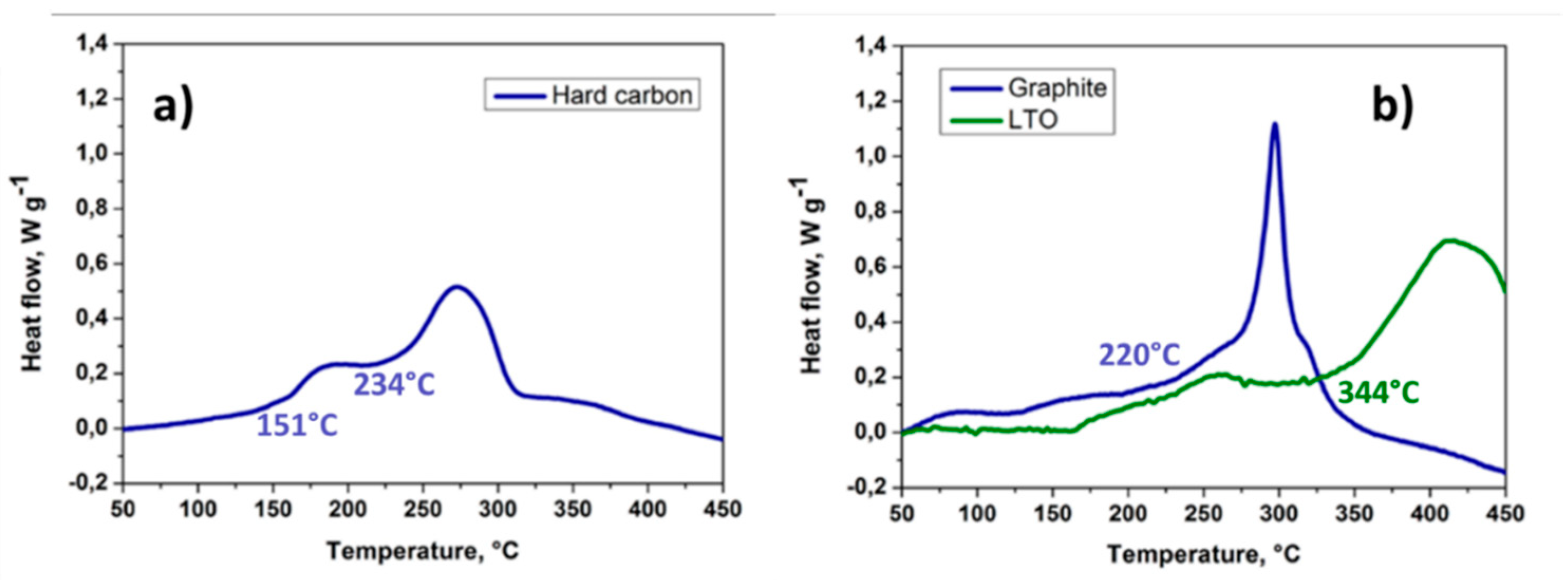
Figure 1. DSC profile curve of a) Na-ion anode (hard carbon) and Li-ion anode (graphite and LTO) after sodiation/lithiation. From reference [95] under CC BY 4.0.
Preprints 113896 g001
Figure 2. DSC profile of graphite/electrolyte after one lithiation. Reprinted with permission from [94].
Preprints 113896 g002
Figure 3. DSC profile of Nax-HC electrodes with solvent mixtures and salt used: a) NaPF6, b) NaClO4 and c) NaTFSI. Reproduced with permission from [73].
Preprints 113896 g003
Figure 4. Effect of over-discharging Na-ion cells to negative voltages. (a) Cycling profile of three-electrode Na-ion cell. Pictures of the cycled (b) anode and (c) cathode. From reference [101] under CC BY 4.0.
Preprints 113896 g004
Figure 5. (a) Cycling curve of Faradion Na-ion cell discharged down to 0 V and potentially held for 24 hours. (b) Cycling stability when the cell is cycled between 4.3 and 0 V and held at this low voltage for 24 hours after each cycle. Reproduced with permission from [102].
Preprints 113896 g005
Figure 6. DSC curves of washed with DMC and dried a) desodiated Na0.58FeO2 cathode powder and b) delithiated Li0.5CoO2 cathode powder after two cycles. Reproduced with permission from [112].
Preprints 113896 g006
Figure 7. DSC curves for Fixed material quantity a) 1 mg of Na0.58FeO2 powder mixed with electrolyte and b) 1 mg Li0.5CoO2 mixed with electrolyte. Fixed electrolyte quantities a) given amount of Na0.58FeO2 powder mixed with 1 μL of electrolyte and b) given amount of Li0.5CoO2 powder mixed with 1 μL of electrolyte. Reproduced with permission from [112].
Preprints 113896 g007
Figure 8. Thermal analysis (TG-DSC) curves of the desodiated NaFeP2O7 phase under Ar flow. Reprinted with permission from [118]. Copyright © 2013 American Chemical Society.
Preprints 113896 g008
Figure 9. Real-time bright-field images of NCO cathode surface charged to a) 3.5 V, b) 4.1 V and c) 4.3 V during heating. Reprinted with permission from [120]. Copyright © 2017 American Chemical Society.
Preprints 113896 g009
Figure 10. DSC curves for different Na and Li-salt electrolytes. Reproduced with permission from [121].
Preprints 113896 g010
Figure 11. TGA profiles of Na salts: NaPF6, NaClO4, NaTFSI, NaFTFSI and NaFSI, and the state-of-the-art LiPF6 salt in LiBs. Reproduced with permission from [73].
Preprints 113896 g011
Figure 12. Flammability and ionic conductivity of 1 M NaPF6/ EC-DEC (1:1, v/v) at different EFPN additive contents. Reproduced with permission from [123].
Preprints 113896 g012
Figure 13. Flammability tests for a) 1 M NaPF6-EC/DEC electrolyte, b) 1.2 M NaTFSI-TMP/BTFE/VC electrolyte, c) Flammability tests on the pouch cells and the post-mortem dissection of the burned cell. Reproduced with permission from [125].
Preprints 113896 g013
Figure 14. Evolution of temperature of NVPF/HC cells on heating with cartridge heaters. Reprinted with permission from [126]. Copyright © 2022 American Chemical Society.
Preprints 113896 g014
Figure 15. Battery sample surface temperature and voltage record changes. From reference [101] under CC BY 4.0.
Preprints 113896 g015
Figure 16. Temperature vs. time plot of the charged NFM/HC cell under thermal stability testing with ARC. Reprinted with permission from [103]. Copyright © 2018 American Chemical Society.
Preprints 113896 g016
Figure 17. Voltage and temperature evolution process of a) external short-circuit, b) overcharge test, c) nail penetration test and d) photographs of pouch cells before and after safety tests. Reproduced with permission from [135].
Preprints 113896 g017
Figure 18. DSC data for uncoated and coated Na[Ni0.6Co0.2Mn0.2]O2 cathode. Reproduced with permission from [108].
Preprints 113896 g018
Disclaimer/Publisher’s Note: The statements, opinions and data contained in all publications are solely those of the individual author(s) and contributor(s) and not of MDPI and/or the editor(s). MDPI and/or the editor(s) disclaim responsibility for any injury to people or property resulting from any ideas, methods, instructions or products referred to in the content.
Copyright: This open access article is published under a Creative Commons CC BY 4.0 license, which permit the free download, distribution, and reuse, provided that the author and preprint are cited in any reuse.
Prerpints.org logo

Preprints.org is a free preprint server supported by MDPI in Basel, Switzerland.

Subscribe

© 2024 MDPI (Basel, Switzerland) unless otherwise stated