Preprint
Article

Electrochemical Performance of Ti Gr. 2 as Electrodes in Contact with Saline Suspension of Clays during Electroflotation Process

Altmetrics

Downloads

59

Views

40

Comments

0

A peer-reviewed article of this preprint also exists.

Submitted:

31 July 2024

Posted:

01 August 2024

You are already at the latest version

Alerts
Abstract
The presence of clays in copper minerals has a significant negative impact during their processing, leading to low recoveries during the flotation process. In saline environments such as seawater, the presence of clays contribute to an increase in operational problems caused by salinity, a decrease in the grade of the copper concentrate, alteration of the rheology of the mineral pulp, a decrease in the selectivity of copper during the flotation process, a reduction in the quality of clarified water, and excessive corrosion of metallic components. This study explores the electroflotation of kaolinite and montmorillonite clays in NaCl solutions using a modified Hallimond tube coupled with Ti Gr. 2 electrodes for bubble generation via water electrolysis, and the corrosion analysis of these electrodes applying the superposition model. The electroflotation results show recovery of clays close to 72.68% for kaolinite, 88.44% for montmorillonite, and 67.36% for a mixtures of both clays. The presence of clays helps reduce the corrosive effects of Ti Gr. 2 from 0.069 A/m2 in NaCl to 0.0073 A/m2 in NaCl with montmorillonite clay.
Keywords: 
Subject: Chemistry and Materials Science  -   Chemical Engineering

1. Introduction

Overexploitation of water sources in hyper-arid and arid regions, such as northern Chile, southern Peru, northern China, and parts of Africa, Asia, and Australia, has led to water scarcity, necessitating the search for new sources and better water management practices [1,2,3]. While mining globally uses a relatively small amount of water, it can be a significant consumer at the local level. In Chilean mining, approximately 3% of the total available water is utilized, drawn from three primary sources: continental water, seawater, and recirculated water. Continental water is sourced from underground aquifers, lakes, rivers, and wetlands. Seawater undergoes desalination by private entities and is then pumped to mining sites. Data from COCHILCO indicates that the use of continental water in 2022 decreased by 10.8% compared to its use in 2018 [4]. However, the use of this source has come under scrutiny due to its dwindling availability and increasing demand, prompting a shift towards seawater usage in mining operations over the years. Regarding continental water usage in mining, we can identify five primary areas: concentration processes, which emerge as the most water-intensive, consuming 74.3% of available resources; hydrometallurgy, which follows closely behind at 10.2%; the mining phase, which accounts for over 5.6% of water usage; smelting and refining operations, which utilize 3.6% of the total water volume; and other uses, including supply to third parties, accounting for 6.3% [4]. In all these cases, the reuse of water is a priority for the sustainability of the process. However, the recirculated water, used to minimize the consumption of freshwater, typically carries lower quality, containing dissolved waste and colloidal particles, such as dissolved components and especially clays, generating a negative effect on the process [5].
Clays are usually dispersed in mineral slurries as ultrafine particles, creating conditions for the slurry to behave as a non-Newtonian fluid, which affects the entire mineral processing chain. In particular, the efficiency of flotation of copper sulfides is severely impacted by clay minerals. The long-term stability of clay colloidal particles in the electrolyte poses significant challenges in mineral processing due to the low shear strength of tailings, limited consolidation and strength gain over time, and difficulties in reclaiming water for subsequent ore processing. These type of minerals can be separated by sedimentation and/or flotation processes, but ultrafine clays pose a challenge for mineral processing due to physical properties such as particle size, shape, and density. These parameters are critical for understanding the behavior of these particles in saline solutions like seawater. The presence of soluble salts can destabilize the colloidal state of clays, enhancing sedimentation and consolidation, promoting strength gain, and improving water recovery. Increased water salinity improves the volume of froth floating by diminishing settling [6]. The primary force controlling the behavior of coarse particles in suspension is particle self-weight, whereas inter-particle forces dominate the settling behavior of fine-grained particles due to their low particle weight and high specific surface area. It has been reported that the aggregation rate of nano-sized clay particles present in oil sand tailings increases with rising NaCl concentration, and that the initial settling rate of oil sand tailings increases with higher pH and/or the presence of divalent cations (Ca2+ and Mg2+) [7].
The presence of clay significantly hampers copper ore flotation, leading to decreased recovery rates and a subsequent decline in concentrate grades. Clays are classified as swelling and non-swelling based on their water-absorption capabilities. Kaolinite is a non-swelling clay with the general composition Al2Si2O5(OH)4, which have features that lies in the prevalence of Al3+ in its octahedral sites, where isomorphic substitutions occur with Mg2+, Fe3+, V3+, and Ti4+ [8]. Montmorillonite is a welling clay with the general composition (Na,Ca)0.3(Al,Mg)2Si4O10(OH)n(H2O), with a nanolayered structure consisting of stacked layers about 1 nm thick [9]. In mineral processing, kaolinite presents numerous challenges, including increased fines during size reduction stages (reaching sizes <20 µm), interfering with the flotation process by affecting bubble stability, altering foam rheology, compromising the selectivity of valuable ore recovery, and reducing the quality of recirculated water, particularly at alkaline pH levels (pH > 8), resulting in the accumulation of suspended particles. On the other hand, montmorillonite clay creates challenges in mineral processing due to its high charge density and small particle size, which result in a tendency to stay dispersed in suspension. In the presence of montmorillonite, it is crucial to adjust the solution ionic strength to avoid significant swelling and eventual disintegration of the clay. Notably, the abundance of Cl- ions and multivalent cations (Al3+, Ca2+, Mg2+, K+, and Na+) in the electrolyte notably enhances the natural sedimentation of montmorillonite compared to their performance in pure water due to an increase in the ionic strength.
A technique to improve water quality in the presence of clays particles is the application of the electroflotation process. This method employs an electrochemical approach to effectively eliminate suspended particles such as colloids, microalgae, or oil from seawater, often serving as a preliminary treatment step. A widespread use of this method is in municipal water treatment and the removal of microalgae or metal ions from municipal wastewater [10,11,12,13,14,15,16]. Despite these advancements, there remains a notable gap in the scientific literature concerning the utilization of electroflotation with seawater in the mining industry [17,18]. Specifically, there is a lack of research on its efficacy in removing ultrafine mineral particles such as clays, pyrite [19], chalcopyrite [20,21], hematite [22], and others minerals [23,24,25]. The liquid-solid separation by electroflotation involves lifting ultrafine particles of clays to the water surface through microbubbles of H2 and Cl2 generated by the seawater splitting process via cathodic and anodic reactions [17,18,26]. The electroflotation process offers several key advantages, notably the absence of chemical additives and the ability to regulate bubble density within the reactor by adjusting the applied potential. In 2012, Ruiyong Chen et al. [27] found that in a 3.5 M NaCl solution, the initiation of Cl2 bubbles at the electrode surface was noted at a current density of approximately 1–2 mA/cm2. By increasing the current density to 20 mA/cm2, tiny rising bubbles with a diameter of 50 μm were observed. Conversely, the study shows that on surfaces exhibiting higher hydrophobicity, bubble coalescence occurred, resulting in the formation of large, coalesced bubbles measuring 1–2 mm in diameter, which covered about 42% of the electrode surface. The application of electroflotation for clays removal in high salinity solutions like seawater (∿0.5 M NaCl) has not been deeply studied.
Corrosion in saline environments poses a significant threat to the durability and effectiveness of equipment used in electroflotation processes, ultimately impacting operational costs. By understanding the corrosion mechanisms inherent in salt electroflotation, we can make informed decisions regarding material selection for equipment construction under aggressive conditions. This proactive approach not only extends the equipment's lifespan but also reduces maintenance expenses while preserving its mechanical integrity. Moreover, corrosion directly alters the properties of electrodes by modifying their surfaces and affecting other components of the electrochemical device [28]. This can lead to a decline in the flotation and recovery capacity of clays, further emphasizing the critical importance of addressing corrosion issues in saline electroflotation environments. The efficiency of ultrafine particle removal via electroflotation hinges on a series of surface electrode reactions and the inherent stability of particles, influenced by their hydrophobicity [17,29].
This study analyzes of the electrochemical behavior of electrodes made of Ti Gr. 2 in contact with saline solutions of NaCl and slurries of kaolinite and montmorillonite clays. The electrochemical reactions and their role in the corrosion rate were studied by linear sweep voltammetry. This study significantly contributes to the state of the art regarding the electroflotation process of saline clay slurry by using the superposition model based on the mixed potential theory to determine the electrochemical and corrosion parameters of Ti Gr. 2. The analysis was conducted using a modified Hallimond tube-electroflotation device across a salinity range of 0.1 to 0.5 M of NaCl under different cell voltage and electroflotation times. Electroflotation of both clays and their mixture was also studied.

2. Materials and Methods

2.1. Electroflotation System

The electroflotation tests were conducted using a modified Hallimond tube, specifically tailored for investigating conventional flotation processes. The Hallimond tube comprises an upper section featuring an angled tube that facilitates the ascent of the floated material to the surface, complemented by a conical receiver designed to capture the floated mass. At the base, provision are made for air inlet and outlet for non-floated fractions. This bottom section was modified to accommodate an electrical component, housing connecting cables directly linked to the power source and electrodes, supplemented with rubber bands to insulate the electrolyte from the cables. This adaptation effectively repurposes the apparatus originally intended for air inflow, facilitating the generation of bubbles from the base. The cell used in this work had a volume of 250 cm3 with two cylindrical electrodes of 6.6 cm2 of Titanium Gr. 2 (Ti Gr. 2), obtained from Balance World Inc., as shown in Figure 1.

2.2. Materials and Solutions

The montmorillonite and kaolinite samples, sourced from Science Words (Los Angeles, CA, USA), underwent comprehensive characterization using cutting-edge techniques as scanning electron microscopy (SEM) equipped with an energy-dispersive X-ray (EDS) analyzer (Hitachi SU 500, Japan, and Zeiss EVO MA 10, Germany), and X-ray diffraction (XRD) (Bruker Advance D8, Billerica, MA, USA). Saline solutions of 0.1, 0.3 and 0.5 M NaCl were meticulously prepared using analytical grade NaCl and deionized water. The pH of the solutions was adjusted using 1 M NaOH. All chemicals were purchased from Merck (Merck, Chile).

2.3. Electroflotation Tests

For the electroflotation experiments, three different synthetic saline slurries were prepared: 1 g/L of kaolinite, 1 g/L of montmorillonite, and 1 g/L of the mixture 1:1 of both clays, considering concentrations of 0.1, 0.3, and 0.5 M of NaCl. The particle size of kaolinite and montmorillonite were equivalents to a –635 mesh Tyler with a d80 of 5 µm. The electroflotation system was operated at room temperature of 19±0.5 °C and atmospheric pressure using a power supply operating at constant cell potentials (Ecell) of 10, 15, and 20 V with operating times of 10, 15, and 20 min.
Colloidal suspension preconditioning was performed in an agitator tank for 30 min at 500 rpm, establishing a fixed pH of 8. Subsequently, for electroflotation, NaCl solutions were homogenized for 15 minutes at 700 rpm using a magnetic stirrer. The suspension was promptly transferred to the reactor and energized based on the assigned test number. Upon completion of a run, the froth layer was thoroughly extracted using a peristaltic pump and collected in a beaker. The collected froth was then filtered using a vacuum pump and dried at 105 °C for 24 h, followed by mass measurement on an analytical scale. Finally, the electroflotation efficiency R M F was determined from the following equation:
R M F = m f m i · 100 %
where, m f represents the total solid mass weighted in the froth, encompassing Ti flocs and clays, and m i is the total mass of clay initially present in the reactor.

2.4. Corrosion Studies for Ti Gr. 2

The experimental corrosion procedure was designed to examine the corrosion behavior of partial electrochemical reactions on Ti Gr. 2 electrode immersed in 0.5 M NaCl solutions in presence and absence of clays, focusing the attention on the hydrogen evolution reaction (HER), oxygen reduction reaction (ORR), and titanium oxidation reaction (TOR). For this purpose, a series of polarization curves were measured in a freshly prepared electrolyte using a Ti Gr. 2 rotating disc electrode. The Ti Gr. 2 electrodes were fabricated from a cylindrical rod with a diameter of 4 mm and a length of 10 mm. This Ti Gr. 2 rod was concentrically inserted using resin adhesive into a PTFE tube with a diameter of 8 mm, which serves as a fixing device to the shaft of the rotating disc electrode cell. The temperature was maintained at 20±0.5 °C using a water-jacketed cell with circulating water through a thermoelectric temperature control device. All the experiments were repeated in triplicate to verify their reproducibility. All potentials reported are referred to the standard hydrogen electrode (SHE).
The electrochemical analysis was performed using a BASI/RDE-2 rotating electrode interface connected to an Epsilon potentiostat/galvanostat (Basi, Indiana, USA). The analysis was carried out separately by linear sweep voltammetry in a conventional 3-electrode cell system using Ti Gr. 2 as working electrodes, a platinum wire as a counter electrode, and Ag/AgCl (4 M KCl Sat.) as a reference electrode. The experimental protocol for polarization data followed a previous work [18,30], covering a potential range between –1100 to 200 mV/SHE at a scan rate of 2 mV/s. The rotation electrode for the Ti Gr. 2 was 1200 rpm.

2.5. Kinetic Corrosion Analysis

The corrosion kinetic investigation was conducted utilizing non-linear fitting applied to experimental polarization data, employing the superposition model based on mixed potential theory. This approach aligns with the methodology outlined in our prior research, focusing on charge transfer, mass diffusion, and passivation mechanism controls, where the total current density can be expressed as follows [18,30,31]:
i = i O 2 + i H 2 + i T i
where, i represents the total current density, i O 2 and i H 2 denote the partial reduction current densities for ORR and HER, respectively, and i T i denotes the partial oxidation current density for TOR. Although experimental measurement of i O 2 , i H 2 and i T i is not directly feasible, their values can be deduced by considering kinetics expressions for each one.
For it, the partial reactions for HER and TOR consider a charge transfer kinetic mechanism, and the ORR considers a mixed charge-diffusion kinetic mechanism, according the follow expressions [30]:
i H 2 = i 0 , H 2 e x p 2.303 · η H 2 t H 2
i O 2 = i 0 , O 2 e x p 2.303 · η O 2 t O 2 1 + i 0 , O 2 e x p 2.303 · η O 2 t O 2 i l , O 2 1
i T i = i 0 , T i e x p 2.303 · η T i t T i
where, the η O 2 = E E e q , O 2 , η H 2 = E E e q , H 2 and η T i = E E e q , T i are the ORR, HER, and TOR overpotentials respectively; i 0 , O 2 , i 0 , H 2 , and i 0 , T i are the exchange current densities for ORR, HER, and TOR respectively; i l , O 2 is the limiting current density for ORR; t O 2 , t H 2 , and t T i are the Tafel slopes for ORR and HER and TOR respectively; E e q , O 2 , E e q , H 2 , and E e q , T i are the equilibrium potentials which are equals to 752 mV, –479 mV and –1804 mV for ORR, HER, and TOR respectively, assuming that the main anodic reaction is T i 2 + + 2 e T i .

3. Results

3.1. Mineralogical Characterization of Clays

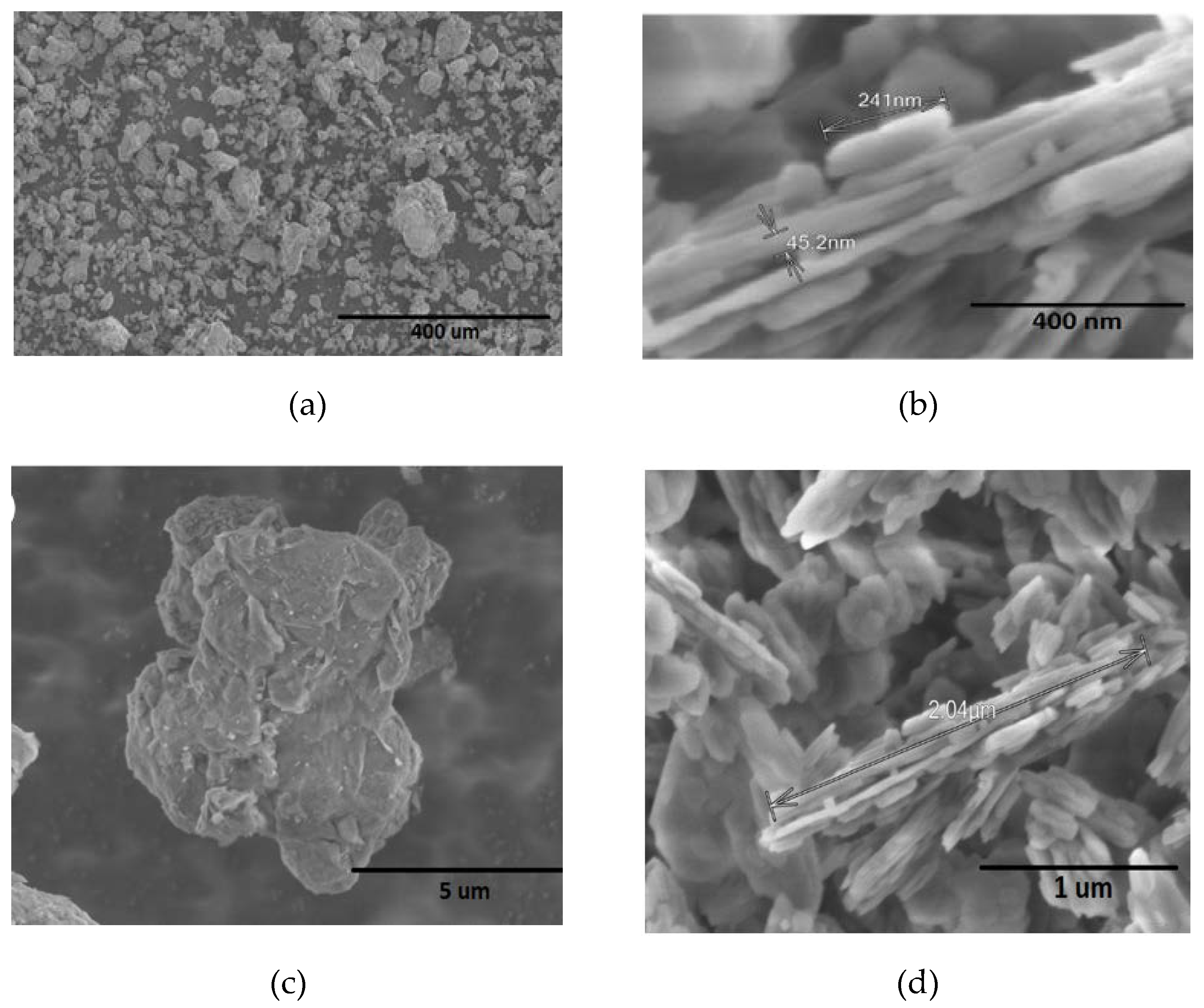
Figure 2 shown morphological patterns of kaolinite and montmorillonite clays as received. For montmorillonite samples (Figure 2a,c), the morphology consists of grains with a flat shape and irregular edges, with particles sizes of 5 μm. Conversely, for kaolinite clay (Figure 2b,d), the morphology consists of a structure of silicate sheets joined together with layers of irregular edges, approximately 1 μm in length. Kaolinite present particles of uniform composition and size, suggesting a more homogeneous structure compared to montmorillonite.
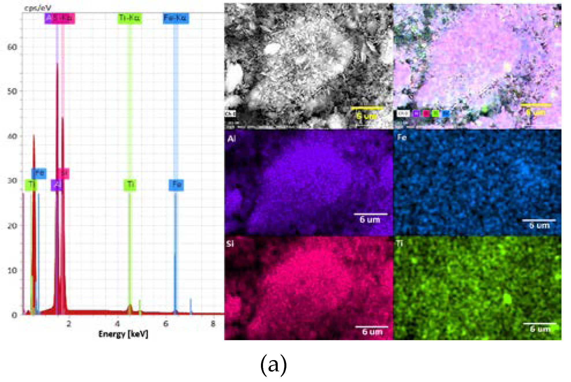
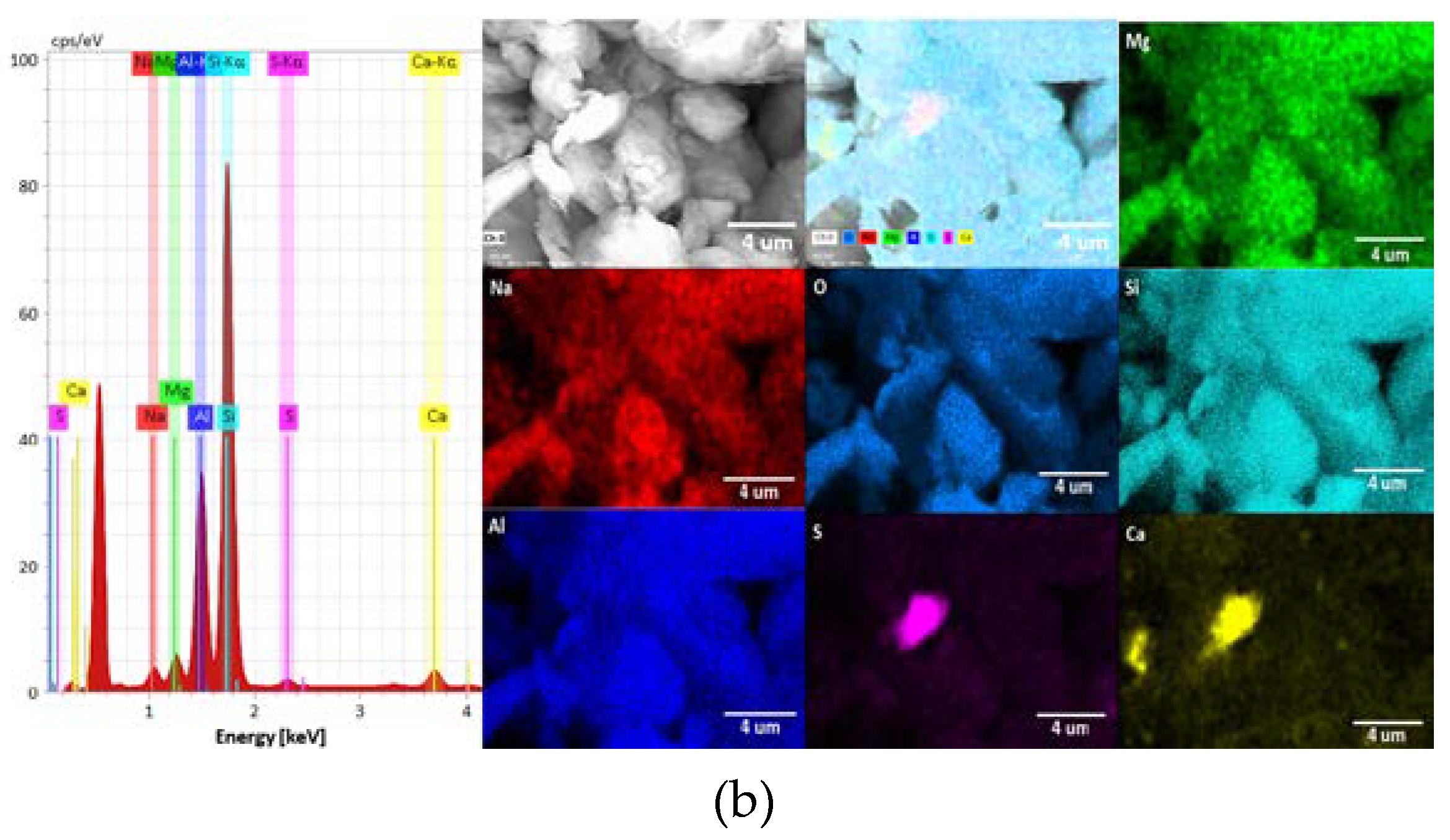
Figure 3 shows images of the elemental analysis for both kaolinite and montmorillonite clays, and Table 1 presents their chemical composition expressed in weight percent (%). For kaolinite clay (Figure 3a), silicon is the predominant element constituting, followed by aluminum, with minor presence of iron and titanium. On the other hand, montmorillonite clay (Figure 3b) exhibits a higher percentage of silicon compared to aluminum, where the sample also contains significant amounts of calcium, magnesium and minor amounts of sodium. These compositions reflect the distinct mineralogical characteristics of kaolinite and montmorillonite, providing insights into their potential effects and behaviors in mineral processing applications.
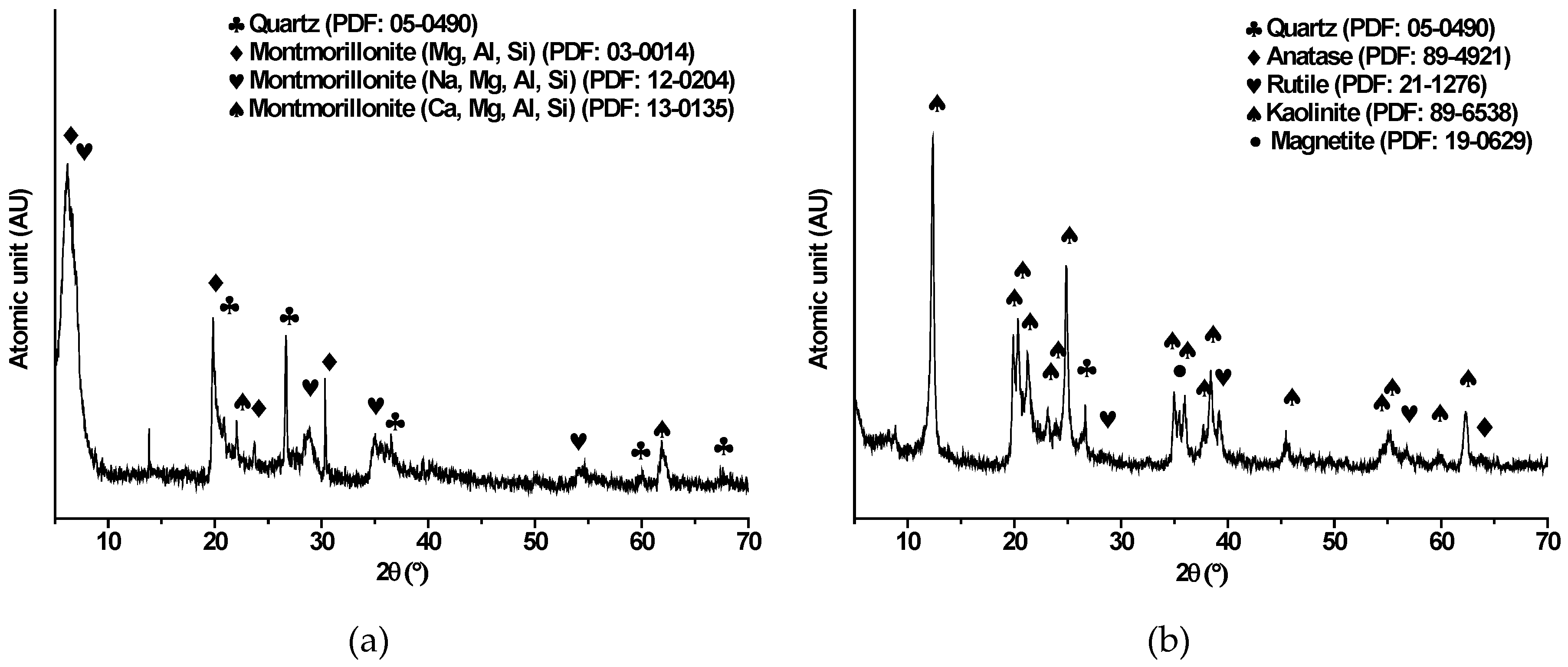
XRD analysis was performed to obtain comprehensive characterization of kaolinite and montmorillonite samples, providing valuable insights into their mineralogical composition as shown in Figure 4. For montmorillonite sample (Figure 4a), the results exhibited signals associated with quartz (SiO2) (PDF 05-0490), and three forms of montmorillonite: montmorillonite with a phase composed by MgOAl2O35SiO2·xH2O (PDF: 03-0014), montmorillonite with sodium content composed by Nax(Al, Mg)2Si4O10(OH)2·zH2O (PDF: 12-0204), and montmorillonite with calcium content composed by Ca0.2(Al, Mg)2Si4O10(OH)2·4H2O (PDF: 13-0135). Conversely, XRD analysis for kaolinite sample (Figure 4b) displayed patterns signals corresponding specifically to kaolinite (PDF 89-6538), and other minor phases such as quartz (SiO2), magnetite (Fe3O4), anatase (TiO2) and rutile (TiO2). Kaolinite and montmorillonite, despite their similar phyllosilicate structures, exhibit distinct compositions and morphologies that can significantly impact processing efficiency. In mineral processing operations, the presence of these clays plays a significant role where several challenges such as increased fines, compromised flotation selectivity, and water quality degradation are observed. Kaolinite's ability to reach ultrafine sizes and interfere with bubble movement exacerbates these issues, while its chemical composition, mainly aluminum and silicon, influences its interactions with other minerals and chemicals. Furthermore, montmorillonite, with its diverse elemental composition including calcium, magnesium, and sodium, introduces additional hurdles due to its complex interactions with processing elements, suggesting potential interactions that may influence flotation behavior, rheological properties, and water quality. Understanding the mineralogical composition and elemental distribution of these clays is crucial for developing tailored strategies to optimize processing efficiency and minimize environmental impacts. Further research into clay-mineral interactions promises innovative solutions to address these challenges effectively.

3.2. Electroflotation of Clays in NaCl Solutions

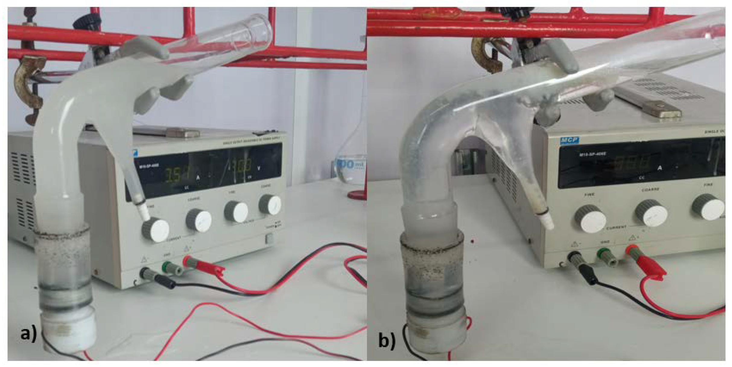
The electroflotation process was performed using a modified Hallimond tube with a pair of cylindrical Ti Gr. 2 electrodes, which were connected from the bottom of the device to a variable power supply as shown in Figure 1. The parameter employed to assess the water quality treated by these electrochemical methods is the electroflotation efficiency (Eq. 1). Figure 5 shows images of the slurries before and after the electroflotation process. In the figure, it is possible to observe the changes in the solution appearance, where a large part of the clays was separated.
During the electroflotation process, the produced foam revealed a sticky consistency, which is a characteristic inherent to clays when they are in contact with aqueous mediums. Through experiments employing applied cell potentials of 10, 15, and 20 V over durations of 10, 15, and 20 min, it was observed that the current intensity varies significantly, as does the amount of clay recovered over time, reaching a steady-state value close to 0.04 A at the end of the electroflotation process, as is tabulated in Table 2. Under this electroflotation conditions, no notable difference was observed in the cell current at the end of process. However, the changes on this variable could be attributed to: (i) the evolution reaction of chlorine at the anode, leading to a decline in conductivity due to the transformation of Cl- ions into Cl2 gas, and (ii) the reduction of active surface sites on the anodic electrode and near the solid-liquid interface due to the oxidation of the anodic electrode and further formation of a passive film of TiO2 following the sequence of electrochemical and chemical reactions [32]:
T i + e T i + 2 + e T i + 3 + e T i + 4
T i + 4 + 4 O H T i O 2 + 2 H 2 O
Although the TiO2 has good corrosion resistance in saline environments, the high cell current and voltage used in the electroflotation can promote the formation of titanium oxychlorides over the passive film by the action of chloride ions, according to the chemical reaction [33]:
T i x O y + 2 C l T i x O y C l 2 + 2 e
Table 2 summarizes the electroflotation parameters for both kaolinite, montmorillonite and their mixtures, under similar electroflotation time, cell voltage and NaCl concentration.
From the table, it is observed that for the three cases of clays (alone and mixtures), lower electrochemical conditions of time, cell voltage, and NaCl concentration, promotes lower electroflotation efficiencies between 1.4 to 2.5%. However, this efficiency parameter increases with the increase of the electrochemical conditions, reaching efficiencies higher to 65%. These results are directly related to the increase in the cell voltage, which increase the cell current, thus promoting a major generation of bubbles on the electrodes, in addition to an increase in the electroflotation time. Both of this parameters are related to the Faraday’s law. Moreover, it is also interesting to observe the effect of the NaCl concentration, which, although it in to obtain a solution of high conductivity, this salt also would promotes corrosion on the electrodes. Under the optimal electroflotation conditions, the results show higher electroflotation efficiencies for kaolinite, reaching a value of 88.44%, compared to montmorillonite and the mixture of clays. These results are directly related to changes on the rheology and froth stability, where the swelling clays like montmorillonite accommodates larges amount of adsorbed water compared with non-swelling clay like kaolinite [34], adversely affecting the electroflotation performance. Additionally, these lower electroflotation efficiencies obtained for montmorillonite and the mixture of both clays are related to the increase in pulp viscosity, which, for example, increases from approximately 1 mPa·s for kaolinite to 8.8 mPa·s for montmorillonite under similar clay concentrations [35], thereby decreasing the electroflotation process.
Therefore, despite the relatively short duration of the electroflotation experiments, the results could be promising, reveling acceptable recovery rates of clays from electroflotation assays in saline environments such as solutions with salts concentrations equivalent to seawater. However, continuous evaluation of the system is essential to investigate potential variations in these parameters over longer electroflotation periods, as well as the influence of the multiple ions typically observed in seawater.

3.3. Electrochemical Behavior of Ti Gr. 2 in Presence of Clays

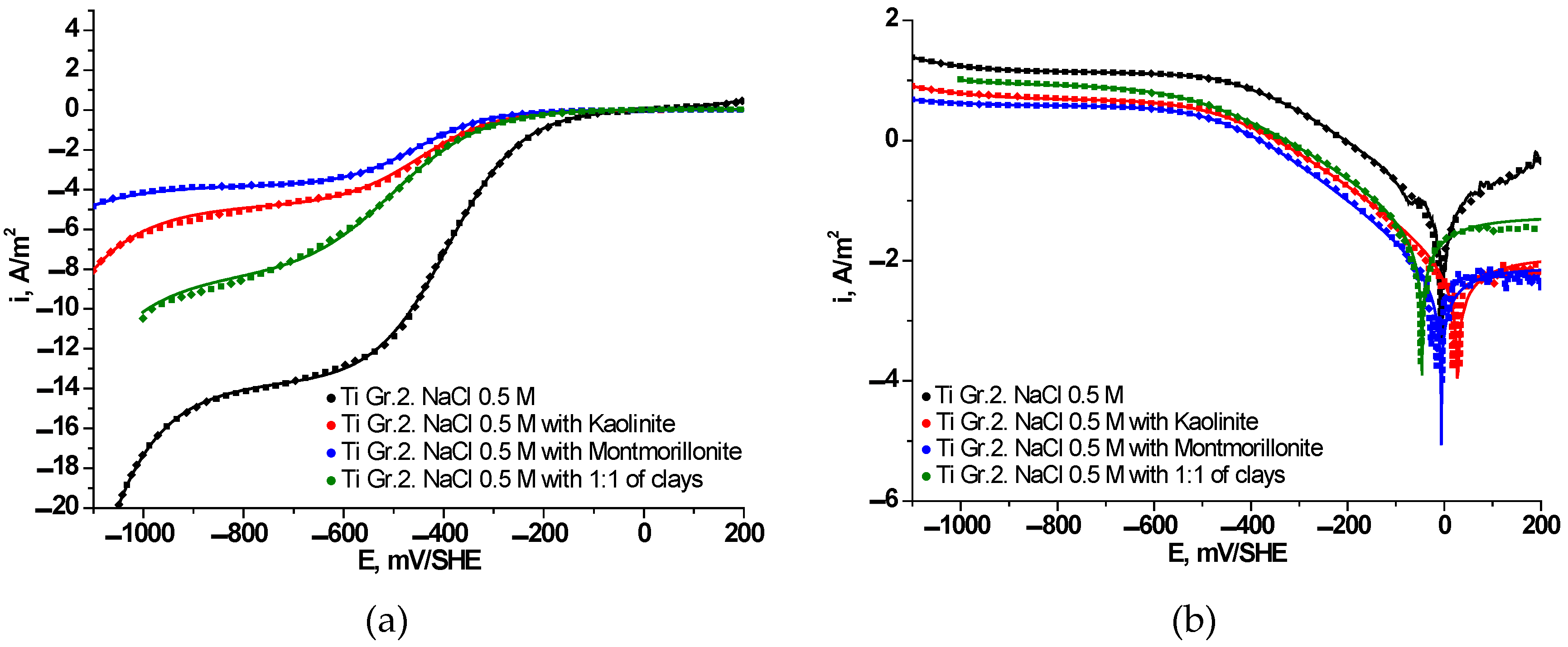
To quantitatively assess the corrosion behavior of Ti Gr. 2 electrodes in alkaline media and the presence of clays, electrochemical linear polarization curves were carried out. Figure 6 depicts polarization curves (Figure 6a) and Tafel curves (Figure 6b) obtained for Ti Gr. 2 immersed in 0.5 M NaCl in absence and presence of clays. Additionally, the figure shows a comparison between experimental values (dotted lines) and fitted values (continuous lines) obtained by applying the superposition model according to Eq. 2. Table 3 summarizes the electrochemical and corrosion parameters determined for ORR, HER and TOR by using Eqs. 3–5. The electrochemical results provide novel information related to the performance of Ti Gr. 2 used for both electrodes in contact with a 0.5 M NaCl solution with a suspension of kaolinite and montmorillonite clays. At potentials more negatives than –800 mV/SHE, the HER, which dominates the current density, reveals an important reduction in the current density in presence of clays compared with a pure solution of 0.5 M NaCl. Considering a fix cathodic potential of –900 mV/SHE, the total current densities were 3.87, 5.53 and 9.24 A/m2 for montmorillonite, kaolinite and the mixture of both clays, respectively, which are low values compared with 15 A/m2 for a solution in absence of clays and containing only NaCl. These variations are in concordance with a smaller Tafel slope value for the test without clays, which also could be due to the adsorption of soluble species from clays samples, disfavoring the electrocatalytic capacity for hydrogen production from water electrolysis.
Further, as expected, the entire cathodic branch for Ti Gr. 2 in 0.5 M NaCl was found to be higher compared with the presence of clays, which revealed lower current densities. Regarding the ORR, the polarization curves showed a good adjustment to a mixed kinetic by charge and mass transfer (see Eq. 4), where the limiting current density ( i l , O 2 ) trends to decrease in presence of clays from 13.68 A/m2 in NaCl solution to 3.8 A/m2 in the presence of montmorillonite clay. These variations in i l , O 2 values for ORR represent a decay in the mass transfer of oxygen dissolved close to 28, 35 and 61% when the Ti Gr. 2 is contact with slurries of montmorillonite, kaolinite, and the mix 1:1 of both clays, respectively, compared to a pure NaCl solution. The decreases oxygen mass transfer from bulk to metallic surface could be associated to changes in the density and viscosity of the clay slurry, which are in turn consistent with the electroflotation recoveries for clays. Thus, it is possible to indicate that the values signify enhanced catalytic activity and greater efficiency in reducing molecular oxygen within a pure salt solution. Furthermore, the kinetic parameters show an interesting alteration when the Ti Gr. 2 is immersed in clays, which could be related to variations in the cell current during the electroflotation process. As shown in Table 3, the Tafel slope for TOR in a NaCl solution has similar values commonly observed in literature [18] ranging around 238 mV/dec; however, for clays slurries, the Tafel slope was found to be much higher, in the range of 15000 to 25000 mV/dec, which are unrealistic values. As shown in Figure 6b, from the inversion potential towards anodic direction, the current density follows a planar tendency with the applied potential for tests in presence of clays, compared to the tendency in a pure NaCl solution where the current density increases with the applied potential. This behavior, along with higher anodic Tafel slopes values in the presence of clay slurries, indicates that the Ti Gr. 2 rapidly passivates with formation of titanium oxides and promoting a good corrosion resistance [36]. Thus, based on this analysis, the exchange current density can be approximated to the passivation current density. The spontaneously passivation of the Ti Gr. 2 electrode is consistent with the current variations during the electroflotation tests. On the other hand, the cathodic kinetic parameter for ORR and HER does not show appreciable variations in clay slurries; however these kinetic parameters were lower than that determined for a pure NaCl solution.
The corrosion rate exhibited by the Ti Gr. 2 electrode in contact with a 0.5 M NaCl solution reveals convinced values of i c o r r equal to 0.0693 A/m2, compared to values obtained for the clays where lower corrosion rates were observed, and equals to 0.0098, 0.0073, and 0.0522 A/m2 for kaolinite, montmorillonite, and the mix 1:1 of both clays, respectively. In the both cases, the i c o r r value obtained is comparable to Ti-Ni alloy electrodes in NaCl solution [37], and close to that observed qualitatively for Ti Gr.2 samples in 3.5% NaCl [38] where an inapplicability of the Tafel law was reported. These values are further supported by the performance of the Tafel curve depicted in Figure 6b, as well as the electrochemical kinetic parameters for both ORR, HER, and TOR presented in Table 3. The corrosion rates are directly related to the electroflotation efficiency, where, as shown in Table 2 and Table 3, lower electroflotation efficiencies were founded for higher corrosion rates. This could be attribute to a competition between anodic titanium oxidation, oxygen and chlorine evolution reactions and the interference of soluble ions from clays and their further combination with hydroxyl anions in solution, such as Al(OH)3 formation. This last effect, associated with the dissolved ions from clays, can be verified by comparing the corrosion rates and electroflotation efficiencies between kaolinite and montmorillonite clays with their dissolution rates [39,40], where a higher corrosion rate of the Ti Gr. 2 electrode in kaolinite slurry could be caused by a high Al/Si concentration relation (~0.85 at pH=4 [39]), compared to the Ti Gr. 2 electrode in montmorillonite slurry, where a low corrosion rate is attributed to a lower Al/Si concentration relation (~0.42 at pH=4 [40]).
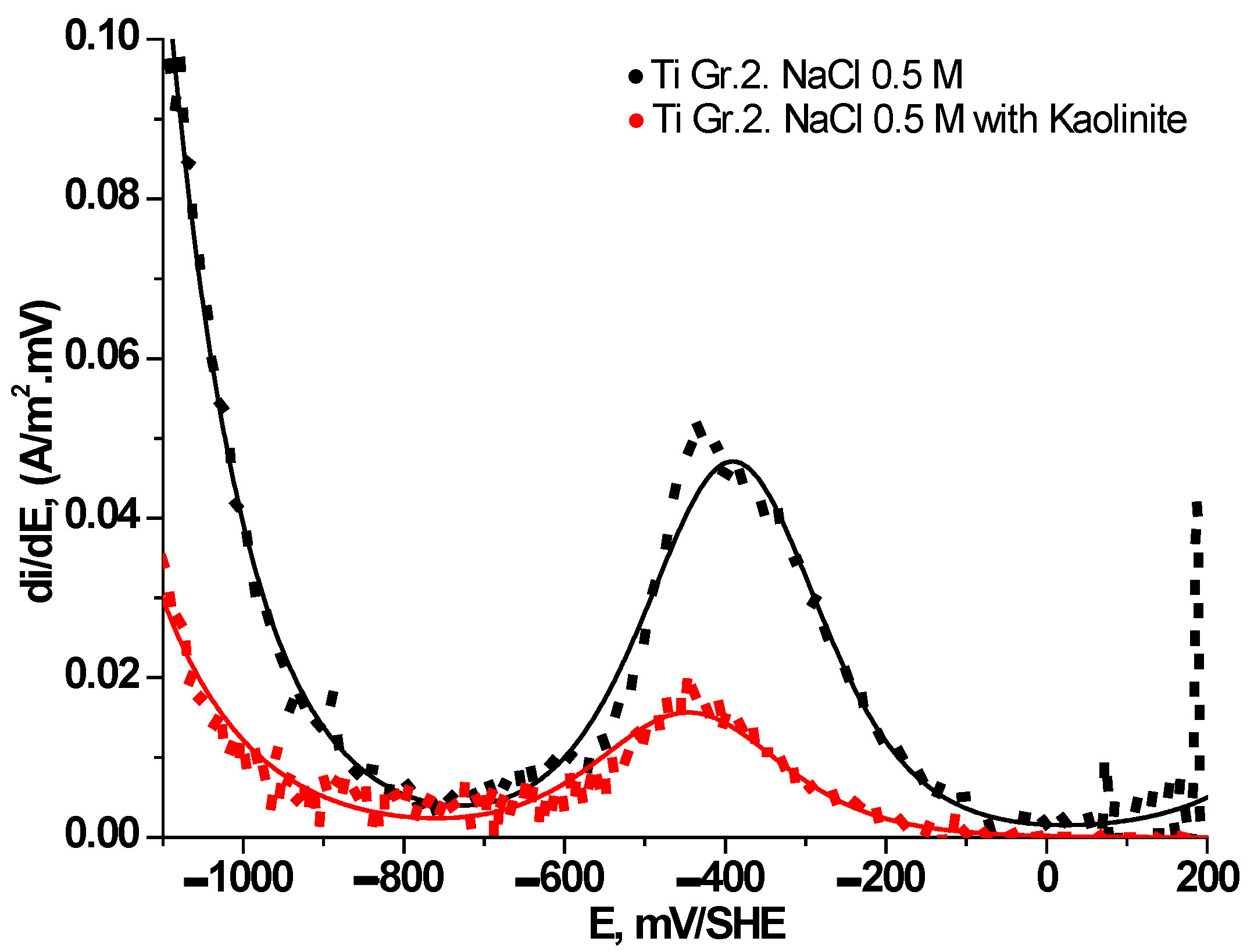
Figure 7 delineates the behavior of the first derivative (di/dE) concerning instantaneous current variation with potential from the cathodic to the anodic direction. Three discernible regions emerge: i) within the potential range of –1100 to –800 mV/SHE, the experimental and fitted results confirm that the charge transfer is the rate-determining step for HER, which is corroborated by higher obtained Tafel slope values ( | t H 2 | >200 mV/dec), revealing faster HER kinetics for the 0.5 M NaCl solution without clays; ii) from –800 to –100 mV/SHE, the cathodic subprocess for ORR only shows a planar plateau between –800 to –650 mV/SHE followed by a symmetric distribution between –650 to –100 mV/SHE with a maximum inflection point, indicating that the ORR is via a 4-electron transfer pathway where a mixed control of charge and mass transfer is the rate-determining step, albeit decreasing the ORR kinetics in the presence of ultrafine clays in the saline solution; iii) within –100 to 200 mV/SHE, the derivative values reveal different tendencies in the NaCl solution without and with the presence of clays, where for kaolinite clay, the results confirm a spontaneous passivation of the Ti Gr. 2 electrode through the observations of the first derivative values with potential, contrary to the tendency observed for the 0.5 NaCl solution which reveals an increases in the di/dE values with potential. Similar results were observed for montmorillonite clay and the 1:1 mixture of both studied clays.
The electroflotation results for kaolinite, montmorillonite and their 1:1 mixture, in conjunction with the kinetic and corrosion parameters for Ti Gr. 2 electrodes, provide novel insights into the concentration process of clays with particle sizes less than 32 µm in aggressive environments such as 0.5 M NaCl solution. Particularly, the kinetic parameters associated with the HER mechanism exhibits intriguing variability when the Ti Gr. 2 electrode interacts with different clay types. This suggests a direct influence of clay presence on the rate of HER at the cathodic electrode. Remarkably, the highest exchange current density is observed under operational conditions that closely mimic real-world scenarios encountered in mineral processing, specifically when operating with saline solutions containing clay mixtures. This heightened exchange current density signifies enhanced efficiency in the release or evolution of H2 under such conditions. Similarly, the higher exchange current density for the ORR indicates rapid reaction processes occurring at the electrode-electrolyte interface, which is critical for the optimal performance of this electrochemical device.
In this study, the exchange current density for HER and ORR in individual kaolinite and montmorillonite slurries was found to be lower than those observed with the clay mixture slurry. This implies that the kinetics achieved with the clay mixture could be an optimal condition for the cathodic subprocess operation. A higher exchange current density can significantly enhance operational efficiency, leading to improved long-term stability.
Furthermore, as indicated previously, the high values of the Tafel slope for HER suggest the adsorption of intermediate products, which could represent the rate-limiting step of the reaction, resulting in a slower response to changes in applied potential without altering the bubble size. However, when conducting experiments with real clays and their impurities, the Tafel slope values can be drastically affected. This is primarily due to their influence on (i) the rate of electron transfer and (ii) the concentration of hydrogen protons. These factors can significantly modify the kinetics of the HER, leading to variations in the observed Tafel slope.

4. Conclusions

The electrochemical performance of Ti Gr.2 as electrodes for the electroflotation process of individual kaolinite and montmorillonite clay, as well as their 1:1 mixture in 0.5 M NaCl solution, was studied. The electroflotation recovery and corrosion behavior of Ti Gr. 2 were investigated using a modified Hallimond tube and the superposition model, respectively. An increase in cell voltage and current lead to an increase in the electroflotation recovery, with maximum recovery rates of 72.68, 88.44 and 67.36% for montmorillonite, kaolinite and their 1:1 mixture, respectively. The electrochemical behavior of Ti Gr. 2 exhibited a high dependence on the presence of clay slurries, where a passivation behavior and a decrease in the kinetics of ORR and HER were observed for the anodic and cathodic reactions, respectively. The corrosion rate in a chloride solution without clays was 0.0693 A/m2, whereas the rates in presence of chloride with clays were lowers, reaching values of 0.0098 A/m2 for kaolinite, 0.0073 A/m2 for montmorillonite, and 0.0522 A/m2 for the 1:1 mixture of both clays. These findings will serve to complement material analyses and optimize the electroflotation process, which have revealed a good application in high saline environments such as seawater.

Author Contributions

Conceptualization, F.M.G.M., A.S. and B.A.-F; methodology, S.S.-A. and S.A.; software, A.S. and A.G.; validation, F.M.G.M., A.S. and A.C.; formal analysis, F.M.G.M., A.S., and B.A.-F.; investigation, A.C., S.S.-A and S.A.; resources, C.P., F.M.G.M. and B.A.-F.; data curation, A.S. and A.G.; writing—original draft preparation, F.M.GM., and A.S.; writing—review and editing, A.C., A.G., C.P., A.S. and F.M.G.M.; supervision, A.S. and F.M.G.M.. All authors have read and agreed to the published version of the manuscript.

Funding

This research received no external funding.

Data Availability Statement

The data presented in this manuscript are available on request from the corresponding author.

Acknowledgments

The authors would like to thank the Programa de Doctorado en Energía Solar of the Universidad de Antofagasta, Chile; and the support of ANID-Chile through the research project FONDECYT Iniciación 11230550; the Project DIUDA N° 22430 carried out by the Facultad de Ingeniería of the Universidad de Atacama; and ANID/ FONDAP 1522A0006 Solar Energy Research Center SERC-Chile.

Conflicts of Interest

The authors declare no conflicts of interest.

References

  1. Shao, D.; Li, X.; Gu, W. A Method for Temporary Water Scarcity Analysis in Humid Region Under Droughts Condition. Water Resour. Manage. 2015, 29, 3823–3839. [Google Scholar] [CrossRef]
  2. Fernandez-Scagliusi, M.Á. Herramientas para lograr un uso sostenible del agua en la minería: la huella hídrica y la huella de agua. Rev. Catalana Dret. Ambient. 2021, 12, 1–37. [Google Scholar] [CrossRef]
  3. Cisternas, L.A.; Gálvez, E.D. The use of seawater in mining. Min. Proc. Ext. Met. Rev. 2018, 39, 18–33. [Google Scholar] [CrossRef]
  4. COCHILCO, 2022, Yearbook: Copper and Other Mineral statistics 2003–2022. Available online: https://www.cochilco.cl/Lists/Anuario/Attachments/27/ANUARIO_ESTADISTICO_COCHILCO%20A%C3%91O%202022.pdf (accessed on 24 May 2024).
  5. Witecki, K.; Polowczyk, I.; Kowalczuk, P. Chemistry of wastewater circuits in mineral processing industry-a review. J. Water Process, 2022, 45, 102509. [Google Scholar] [CrossRef]
  6. Zhang, N.; Chen, X.; Peng, Y. The interaction between kaolinite and saline water in affecting the microstructure, rheology and settling of coal flotation products. Powder Technol. 2020, 372, 76–83. [Google Scholar] [CrossRef]
  7. Gorakhki, M.H.; Bareither, C.A. Salinity effects on sedimentation behavior of kaolin, bentonite, and soda ash mine tailings. Appl. Clay Sci. 2015, 114, 593–602. [Google Scholar] [CrossRef]
  8. Rand, B.; Melton, I.E. Particle interactions in aqueous kaolinite suspensions. I. Effect of pH and electrolyte upon the mode of particle interaction in homoionic sodium kaolinite suspensions. J. Colloid Interface Sci. 1977, 60, 308–320. [Google Scholar] [CrossRef]
  9. Yaghmaeiyan, N.; Mirzaei, M.; Delghavi, R. Montmorillonite clay: Introduction and evaluation of its applications in different organic syntheses as catalyst: A review. Results Chem. 2022, 4, 100549. [Google Scholar] [CrossRef]
  10. Romanov, A.M. Electroflotation in Waste Water Treatment: Results and Perspectives. In Mineral Processing and the Environment; Springer: Berlin, Germany, 1998; pp. 335–360. [Google Scholar]
  11. Srinivasan, V.; Subbaiyan, M. Electroflotation Studies on Cu, Ni, Zn, and Cd with Ammonium Dodecyl Dithiocarbamate. Sep. Sci. Technol. 1989, 24, 145–150. [Google Scholar] [CrossRef]
  12. Alexandrova, L.; Nedialkova, T.; Nishkov, I. Electroflotation of Metal Ions in Waste Water. Int. J. Miner. Process. 1994, 41, 285–294. [Google Scholar] [CrossRef]
  13. Oussedik, S.M.; Khelifa, A. Reduction of Copper Ions Concentration in Wastewaters of Galvanoplastic Industry by Electroflotation. Desalination 2001, 139, 383. [Google Scholar] [CrossRef]
  14. Khelifa, A.; Moulay, S.; Naceur, A.W. Treatment of Metal Finishing Effluents by the Electroflotation Technique. Desalination 2005, 181, 27–33. [Google Scholar] [CrossRef]
  15. Merzouk, B.; Gourich, B.; Sekki, A.; Madani, K.; Chibane, M. Removal Turbidity and Separation of Heavy Metals Using Electrocoagulation-Electroflotation Technique. A Case Study. J. Hazard Mater. 2009, 164, 215–222. [Google Scholar] [CrossRef] [PubMed]
  16. Zouboulis, A.I.; Matis, K.A. Cadmium Ion Removal by Electroflotation onto Sewage Sludge Biomass. Int. J. Environ. Waste Manag. 2012, 9, 245–256. [Google Scholar] [CrossRef]
  17. Madrid, F.M.G.; Arancibia-Bravo, M.P.; Sepúlveda, F.D.; Lucay, F.A.; Soliz, A.; Cáceres, L. Ultrafine Kaolinite Removal in Recycled Water from the Overflow of Thickener Using Electroflotation: A Novel Application of Saline Water Splitting in Mineral Processing. Molecules 2023, 28, 3954. [Google Scholar] [CrossRef] [PubMed]
  18. Madrid, F.M.G.; Arancibia-Bravo, M.; Cisterna, J.; Soliz, A.; Salazar-Avalos, S.; Guevara, B.; Sepúlveda, F.; Cáceres, L. Corrosion of Titanium Electrode Used for Solar Saline Electroflotation. Materials 2023, 16, 3514. [Google Scholar] [CrossRef]
  19. Kydros, K.A.; Gallios, G.P.; Matis, K.A. Electrolytic Flotation of Pyrite. J. Chem. Technol. Biotechnol. 1994, 59, 223–232. [Google Scholar] [CrossRef]
  20. Bhaskar Raju, G.; Khangaonkar, P.R. Electro-Flotation of Chalcopyrite Fines. Int. J. Miner. Process. 1982, 9, 133–143. [Google Scholar] [CrossRef]
  21. Makuei, F.; Tadesse, B.; Albijanic, B.; Browner, R. Electroflotation of Ultrafine Chalcopyrite Particles with Sodium Oleate Collector. Miner. Eng. 2018, 120, 44–46. [Google Scholar] [CrossRef]
  22. Hacha, R.R.; LeonardoTorem, M.; Gutiérrez Merma, A.; da Silva Coelho, V.F. Electroflotation of Fine Hematite Particles with Rhodococcus Opacus as a Biocollector in a Modified Partridge–Smith Cell. Miner. Eng. 2018, 126, 105–115. [Google Scholar] [CrossRef]
  23. Llerena, C.; Ho, J.C.K.; Piron, D.L. Effects of pH on Electroflotation of Sphalerite. Chem. Eng. Commun. 1996, 155, 217–228. [Google Scholar] [CrossRef]
  24. Liu, A.; Fan, P.; Han, F.; Han, H.; Li, Z.; Wang, H.; Fan, M. Effect of Electroflotation on Quartz and Magnetite and Its Utilization on the Reverse Flotation of Magnetic Separation Concentrate. Miner. Eng. 2022, 175, 107292. [Google Scholar] [CrossRef]
  25. Tadesse, B.; Albijanic, B.; Makuei, F.; Browner, R. Recovery of Fine and Ultrafine Mineral Particles by Electroflotation—A Review. Miner. Process. Extr. Metall. Rev. 2019, 40, 108–122. [Google Scholar] [CrossRef]
  26. Hernlem, B.J.; Tsai, L.-S. Chlorine Generation and Disinfection by Electroflotation. J. Food Sci. 2000, 65, 837–837. [Google Scholar] [CrossRef]
  27. Chen, R.; Trieu, V.; Natter, H.; Kintrup, J.; Bulan, A.; Hempelmann, R. Wavelet analysis of chlorine bubble evolution on electrodes with different surface morphologies. Electrochem. Commun. 2012, 22, 16–20. [Google Scholar] [CrossRef]
  28. Mraz, R.; Krysa, J. Dimensionally Stables Anodes with a Long Lifetime for Electroflotation. In Precision Process Technology; Springer: Berlin/Heidelberg, Germany, 1993; pp. 681–688. [Google Scholar]
  29. Tadesse, B.; Albijanic, B.; Makuei, F.; Browner, R. Recovery of Fine and Ultrafine Mineral Particles by Electroflotation—A Review. Miner. Process. Extr. Metall. Rev. 2019, 40, 108–122. [Google Scholar] [CrossRef]
  30. Soliz, A.; Cáceres, L. Corrosion behavior of carbon steel in LiBr in comparison to NaCl solutions under controlled hydrodynamic conditions. Int. J. Electrochem. Sci. 2015, 10, 5673–5693. [Google Scholar] [CrossRef]
  31. Soliz, A.; Cáceres, L.; Pineda, F.; Galleguillos, F. Erosion–Corrosion of AISI 304L Stainless Steel Affected by Industrial Copper Tailings. Metals 2020, 10, 1005. [Google Scholar] [CrossRef]
  32. Zhong, Y.; Yang, Q.; Li, X.; Yao, F.; Xie, L.; Zhao, J.; Chen, F.; Xie, T.; Zeng, G. Electrochemically Induced Pitting Corrosion of Ti Anode: Application to the Indirect Reduction of Bromate. Chem. Eng. J. 2016, 289, 114–122. [Google Scholar] [CrossRef]
  33. El-Ghenymy, A.; Alsheyab, M.; Khodary, A.; Sirés, I.; Abdel-Wahab, A. Corrosion Behavior of Pure Titanium Anodes in Saline Medium and Their Performance for Humic Acid Removal by Electrocoagulation. Chemosphere 2020, 246, 125674. [Google Scholar] [CrossRef]
  34. Hatch, C.D.; Wiese, J.S.; Crane, C.C.; Harris, K.J.; Kloss, H.G.; Baltrusaitis, J. Water Adsorption on Clay Minerals as a Function of Relative Humidity: Application of BET and Freundlich Adsorption Models. Langmuir 2012, 28, 1790–1803. [Google Scholar] [CrossRef] [PubMed]
  35. Chen, L.; Zhao, Y.; Bai, H.; Ai, Z.; Chen, P.; Hu, Y.; Song, S.; Komarneni, S. Role of Montmorillonite, Kaolinite, or Illite in Pyrite Flotation: Differences in Clay Behavior Based on Their Structures. Langmuir 2020, 36, 10860–10867. [Google Scholar] [CrossRef] [PubMed]
  36. Xue, C.; Zhang, P.; Wei, D.; Hu, H.; Li, F.; Yang, K. Corrosion and Tribocorrosion Behaviors for TA3 in Ringer’s Solution after Implantation of Nb Ions. Appl. Sci. 2020, 10, 8329. [Google Scholar] [CrossRef]
  37. Lazić, M.M.; Mitić, D.; Radović, K.; Đorđević, I.; Majerič, P.; Rudolf, R.; Grgur, B.N. Corrosion Behavior of Nickel–Titanium Continuous-Casted Alloys. Metals 2024, 14, 88. [Google Scholar] [CrossRef]
  38. Kostelac, L.; Pezzato, L.; Colusso, E.; Natile, M.M.; Brunelli, K.; Dabalà, M. Black PEO Coatings on Titanium and Titanium Alloys Produced at Low Current Densities. Appl. Sci. 2023, 13, 12280. [Google Scholar] [CrossRef]
  39. Ganor, J.; Mogollón, J.L.; Lasaga, A.C. The effect of pH on kaolinite dissolution rates and on activation energy. Geochim. Et. Cosmochim. Acta 1995, 59, 1037–1052. [Google Scholar] [CrossRef]
  40. Rozalén, M.L.; Huertas, F.J.; Brady, P.V.; Cama, J.; García-Palma, S.; Linares, J. Experimental study of the effect of pH on the kinetics of montmorillonite dissolution at 25 °C. Geochim. Cosmochim. Acta 2008, 72, 4224–4253. [Google Scholar] [CrossRef]
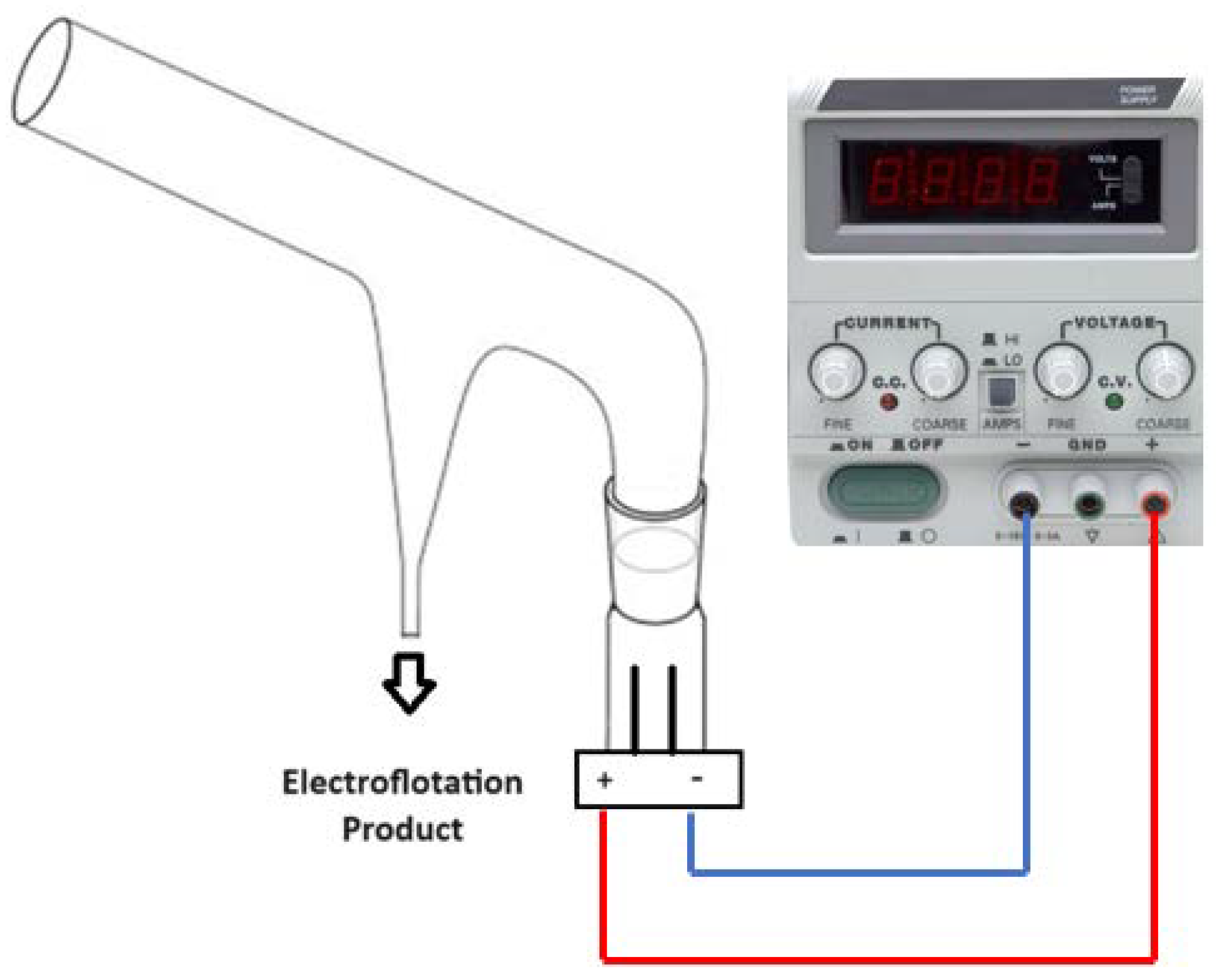
Figure 1. Schematic diagram of a modified Hallimond tube for electroflotation tests.
Preprints 113860 g001
Figure 2. SEM images of (a, c) montmorillonite and (b, d) kaolinite clays.
Preprints 113860 g002
Figure 3. Elemental mapping by EDS analysis of (a) kaolinite and (b) montmorillonite clays.
Preprints 113860 g003aPreprints 113860 g003b
Figure 4. XRD patterns of (a) montmorillonite and (b) kaolinite clays.
Preprints 113860 g004
Figure 5. Modified Hallimond tube, (a) before and (b) after electroflotation process of clays.
Preprints 113860 g005
Figure 6. Polarization (a) and Tafel (b) curves for Ti Gr. 2 in contact with 0.5 M NaCl and slurry of clays. Experimental curve (dotted line) and fitted curve (line) obtained from superposition model.
Preprints 113860 g006
Figure 7. First derivative curve of current density-potential data for Ti Gr. 2 in 0.5 M NaCl and solution kaolinite slurry.
Preprints 113860 g007
Table 1. Chemical composition of kaolinite and montmorillonite clays.
Elements Kaolinite, wt% Montmorillonite, wt%
Fe 2.47 -
Al 44.53 21.71
Si 48.57 67.48
Ti 4.44 -
Na - 0.83
Mg - 1.81
S - 1.91
Ca - 6.25
Table 2. Operational and response parameters obtained for the electroflotation of clays using a modified Hallimond tube with an anode and cathode made of Ti Gr. 2.
Test Clay type NaCl, M tEF,
min
Ecell,
V
Icell, A
(t=0 min)
Icell, A
(t=tEF)
%RMF
1 Montmorillonite 0.1 10 10 0.14 0.05 1.49
2 0.3 15 15 0.17 0.05 43.52
3 0.5 20 20 0.40 0.03 72.68
4 Kaolinite 0.1 10 10 0.15 0.03 2.37
5 0.3 15 15 0.23 0.04 45.72
6 0.5 20 20 0.80 0.03 88.44
7 Mix (1:1 wt%) Kao/Mont 0.1 10 10 0.40 0.04 2.33
8 0.3 15 15 0.56 0.04 31.36
9 0.5 20 20 0.71 0.05 67.36
Table 3. Kinetic and corrosion parameters for Ti Gr. 2 electrode in NaCl and clays slurries, obtained from applying the superposition model.
Parameters 0.5M NaCl 0.5 M NaCl + (1:1) Kao./Mont. 0.5 M NaCl + 1000 ppm Kao. 0.5 M NaCl + 1000 ppm Mont.
i 0 , T i , A/m2 1.99×10⁻⁹ 5.13×10⁻² 9.60×10⁻³ 7.20×10⁻³
t T i , mV/dec 238 231629 159369 243684
i 0 , O 2 , A/m2 –2.03×10⁻⁶ –7.15×10⁻⁶ –7.57×10⁻⁷ –1.83×10⁻⁷
t O 2 , mV/dec –168 –207 –171 –165
i l , O 2 , A/m2 –13.68 –8.38 –4.76 –3.79
i 0 , H 2 , A/m2 –1.46×10⁻² –1.44×10⁻² –1.23×10⁻² –3.54×10⁻³
t H 2 , mV/dec –217 –247 –256 –253
E c o r r , mV/SHE –7 –48 27 -6
i c o r r , A/m2 0.0693 0.0522 0.0098 0.0073
Disclaimer/Publisher’s Note: The statements, opinions and data contained in all publications are solely those of the individual author(s) and contributor(s) and not of MDPI and/or the editor(s). MDPI and/or the editor(s) disclaim responsibility for any injury to people or property resulting from any ideas, methods, instructions or products referred to in the content.
Copyright: This open access article is published under a Creative Commons CC BY 4.0 license, which permit the free download, distribution, and reuse, provided that the author and preprint are cited in any reuse.
Prerpints.org logo

Preprints.org is a free preprint server supported by MDPI in Basel, Switzerland.

Subscribe

© 2024 MDPI (Basel, Switzerland) unless otherwise stated