1. Introduction
The energy consumption has been increasing with economy development rapidly. According to the Energy White Paper [
1], the energy consumption was 14.4 billion ton based on equivalent of oil in 2022. On the other hand, the renewable energy is paid attention to introduce mode to meet the increase in energy consumption as well as to solve the global warming problem. According to the data base [
1], the ratio of renewable energy including hydro to total energy consumption was 14.2 % in 2022 [
1]. It is expected that the renewable energy will increase more and more in the world.
Using renewable energy to produce H
2 is a promising way to utilize renewable energy. There are several approaches to produce H
2, including producing H
2 from biogas dry reforming. Biogas which consists of CH
4 (ratio: 55–75 vol%) and CO
2 (ratio: 25–45 vol%) [
2] can be produced by fermentation of the action of anaerobic microorganisms on raw materials such as garbage, livestock and sewage sludge. It is known from the International Energy Agency [
3] that the biogas equivalent to 1.46 EJ was produced in 2020. According to the International Energy Agency [
3], the amount of produced biogas based on energy value was approximately five times as large as that in 2000. We can expect that the produced biogas will increase more and more. Biogas is usually used as a fuel for gas engine and micro gas turbine [
4]. However, the power generation is smaller than using a natural gas due to consisting of CO
2 of approximately 40 vol%. In this study, a biogas is proposed to be used as a feedstock to produce H
2 via a thermally powered biogas dry reforming process. The produced H
2 can be used as a fuel for solid oxide fuel cell (SOFC) [
5]. CO which is a by-product of biogas dry reforming can also be used as a fuel for SOFC, resulting a more effective energy production system.
This study proposes a system combining the above described energy production system with a solar collector to supply the heat, which is needed for a biogas dry reforming, because it is an endothermic reaction. There are some studies reporting the combined system with a solar collector to produce H
2 using a heat for the chemical reaction [
6,
7,
8,
9,
10,
11,
12,
13,
14]. The numerical investigating the effect of peak heat flux, inlet flow rate and CH
4/CO
2 feed ratio on reaction temperature, reaction rates, conversion of syngas, syngas yield, carbon deposition, and other thermochemical characteristics of the porous material filled in solar collector under high-flux concentrated irradiation was reported [
6]. Energy conversion equation and heat transfer equation, e.g. the equation on radiation heat transfer as well as chemical reactions were solved by CFD. As a result, the peak heat flux of the incident solar radiation performed a linear relation with the reaction temperature. The peak heat flux over 0.734 MW/m
2 would decrease CH
4 conversion and H
2 yield, resulting in the reduction of the syngas yield. The experimental study using solar scheffler collector for biogas dry reforming was conducted [
7]. The parabolic solar collector which could increase the temperature of biogas from 383 K to 773 K performed H
2 yield of 16 % and CO yield of 10 %. CH
4 conversion as well as CO
2 conversion increased with the rise in temperature. The solar thermochemical system including a parabolic trough solar collector and a membrane reactor was proposed and investigated experimentally to decrease the reaction temperature of dry reforming to a mid/low temperature range (573 K–773 K) [
8]. The conversion rate of CH
4 at 673 K and 698 K reached 20.27 % and 30.00 %, respectively. Compared to a traditional system powered by fossil fuel energy, the CO
2 emission could reduce 6.26 kg/m
3 annually at 773 K with H
2 permeate pressure of 10
-3 bar. The thermodynamic analysis on solar CH
4 steam reforming with H
2 permeation membrane reactor at mid/low temperature was carried out numerically [
9]. Solar trough collector was assumed to provide the heat for CH
4 steam reforming. An optimal conversion rate range of CH
4 for efficient solar CH
4 membrane reforming was calculated, resulting that the net solar-to-fuel efficiency reached 38.25 % at 673 K which was lower temperature than normal operation temperature due to non-equilibrium state of CH
4 steam reforming by means of membrane. A reflux solar CH
3OH steam reforming reactor system was proposed and investigated numerically [
10]. Parabolic solar collector was adopted to provide the heat for CH
3OH steam reforming. When the length of flow channel of the reflux solar CH
3OH steam reforming reactor was lengthened, the reaction was carried out thoroughly. Since the temperature in the reactor increased generally due to the recovery of the outlet fluid heat, the radiative heat loss increased slightly. The energy conversion efficiency varied slightly with the inlet mass flow rate. The parabolic trough solar receiver-reactor was proposed and investigated numerically using the CFD software, ANSYS Fluent for continuous and efficient H
2 production via CH
3OH steam reforming reaction [
11]. A larger inlet temperature caused a higher reaction temperature and a consequent higher reaction rate. However, a higher working temperature also provided a relatively larger energy fraction of thermal loss. The parabolic trough solar receiver-reactors of gradually varied porosity catalyst beds were proposed and investigated for cost efficient H
2 production [
12]. A 3D comprehensive model was developed for the parabolic trough solar receiver-reactors of CH
3OH steam reforming reaction in porous Cu/ZnO/Al
2O
3 catalyst packed beds, by combining the finite volume method with a comprehensive kinetic model. The top part of the reactor had lower temperature with a larger porosity, resulting that a relatively larger fluid flow velocity and heat convection between the bottom part and the top part of the reactor occurred. The average Nu number increased by 24.39 % though the average friction factor decreased by 5.91 %.
According to NEDO Renewable Energy Technology White Paper [
13], parabolic trough type, Fresnel type, tower type and dish type are main type of concentration solar collectors installed in the world. The efficiency of parabolic trough type, Fresnel type, tower type and dish type is 15 %, 8 %– 10 %, 20 % – 35 % and 25 % – 30 %, respectively. Additionally, the land utilization efficiency for parabolic trough type, Fresnel type and tower type is 25 % – 40 %, 60 % – 80 % and 20 % – 25 %, respectively. When using the solar thermal power generation for the plant size below 250 MW and over 250 MW, the power generation cost of parabolic trough type is approximately 0.2 USD/kWh – 0.3 USD/kWh and 0.22 USD/kWh – 0.27 USD/kWh, respectively. Although the power generation cost depends on the sun light illumination condition strongly in this study, the parabolic trough solar collector was selected to be studied.
Considering the system proposed by this study, the location where the system is installed is important since the solar intensity influences the performance of solar collector [
5]. In addition, the energy consumption and the CO
2 emission in Asia, e.g. China, India, Japan and so on increase rapidly [
1]. The average global horizontal solar irradiance in India is 5.0 kWh/(m
2・day) – 5.5 kWh/(m
2・day), which is much larger than that in China and Japan, e.g. 3.0 kWh/(m
2・day) – 4.5 kWh/(m
2・day) and 3.0 kWh/(m
2・day) – 3.5 kWh/(m
2・day), respectively [
14]. Therefore, this paper conducted a hypothetical case study by assuming to install the proposed system in Kolkata, India.
However, there is no study on assessment of performance of solar collector as well as the energy production system proposed by this study which is assumed to be installed in India. Therefore, the aim of this study is to understand the influence of the climate data in India on the performances of solar collectors with different sizes and heat mass flow rate of transfer fluid, e.g. the simulated biogas as well as the performance of the combination system proposed. The weather data of Kolkata was from METPV-ASIA [
15]. This study used the developed heat transfer model of the parabolic trough solar collector in previous studies [
16]. The temperature of heat transfer fluid out of the parabolic trough solar collector could range approximately 700 K – 873 K [
17,
18]. Since the biogas dry reforming could happen in the temperature range from 673 K to 873 K as per the previous experimental studies conducted by authors [
19,
20], this study thinks that the parabolic trough solar collector is suitable. The authors have also adopted the specific characteristics of a biogas dry reforming reactor developed previously to calculate the amount of produced H
2 [
19,
20] and the power generated by SOFC using H
2 obtained from a biogas dry reforming reactor. The heat transfer fluid which consists of CH
4 and CO
2 flows into the solar collector. After the heat transfer fluid is heated by solar collector, it flows into the biogas dry reforming reactor. H
2 will then be produced in the reactor via the biogas dry reforming process. The produced H
2 is provided to SOFC as a fuel, resulting that the electricity is generated. In this study, the impact of climate condition of Kolkata in India on the performance of solar collectors with different lengths of parabolic trough solar collector (
dx) and mass flow rate of heat transfer fluid (
m) has been investigated. In addition, the amount of H
2 produced by biogas dry reforming (
GH2), the amount of power generated by SOFC (
PSOFC) and the maximum possible households (
N) whose electricity demand could be met by the energy system proposed have been also evaluated considering the performance of solar collector with the different
dx and
m.
3. Combined Energy Production System Proposed by This Study
Figure 3 illustrates the proposed system consisting of solar collector, biogas dry reforming reactor and SOFC. In the proposed system, the heat transfer fluid which consists of CH
4 and CO
2 flows into solar collector. After being heated by solar collector, the heat transfer fluid flows into biogas dry reforming reactor. H
2 is produced in the reactor via biogas dry reforming process. The produced H
2 is supplied for SOFC as a fuel. As a result, the electricity and heat is generated (In this study, only the electricity is considered). The by-product of the process, CO was not considered in this study.
To calculate the amount of H
2 produced through the biogas dry reforming reactor, this study follows the reaction scheme of biogas dry reforming as follows:
We set the molar ratio of CH
4 and CO
2 is 2.51×10
-3 mol/s and 1.67×10
-3 mol/s, respectively when
m = 0.005 kg/s. In this study,
m is changed by 0.005, 0.010, 0.015 and 0.030 kg/s. According to Equation (19) and the molar flow rate when
m = 0.005 kg/s, the molar flow rate of produced H
2 can be estimated to be 3.34×10
-3 mol/s. According to the authors’ previous experimental studies investigating the impact of the reaction temperature on the performance of biogas dry reforming corresponding to
Tfb in this study from 673 K to 873 K [
19,
20], the best performance of biogas dry reforming was obtained at 873 K. The conversion ratio of H
2 is assumed to be 100 % and 10 % respectively [
19,
20].
To calculate the power generated by SOFC, the lower heating value of H
2 (= 10.79 MJ/m
3N) and the power generation efficiency of commercial SOFC of 55 % [
26] were used. The power generated by SOFC in the case of the conversion ratio of H
2 = 100 % can be estimated as follows:
In addition, this study estimated the number of maximum possible households whose electricity demand could be met by the power generated by SOFC. The monthly data for the electricity demand of a couple households was used in this study [
27].
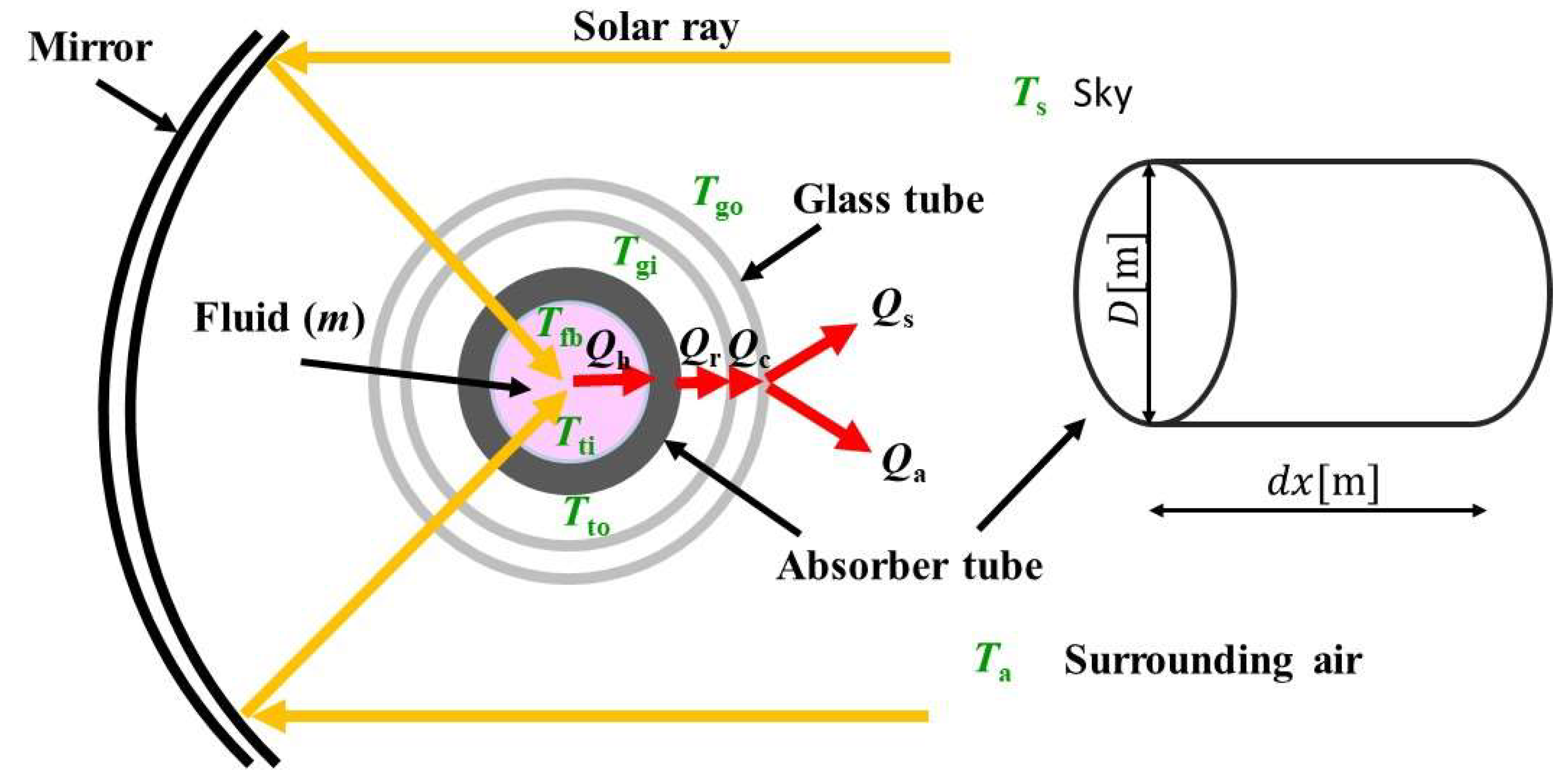
Figure 1.
Schematic drawing of heat transfer model of solar collector investigated in this study.
Figure 1.
Schematic drawing of heat transfer model of solar collector investigated in this study.
Figure 2.
Thermal resistance diagram of heat transfer model proposed by this study.
Figure 2.
Thermal resistance diagram of heat transfer model proposed by this study.
Figure 3.
Combined energy production system consisting of solar collector, biogas dry reforming reactor and SOFC proposed by this study.
Figure 3.
Combined energy production system consisting of solar collector, biogas dry reforming reactor and SOFC proposed by this study.
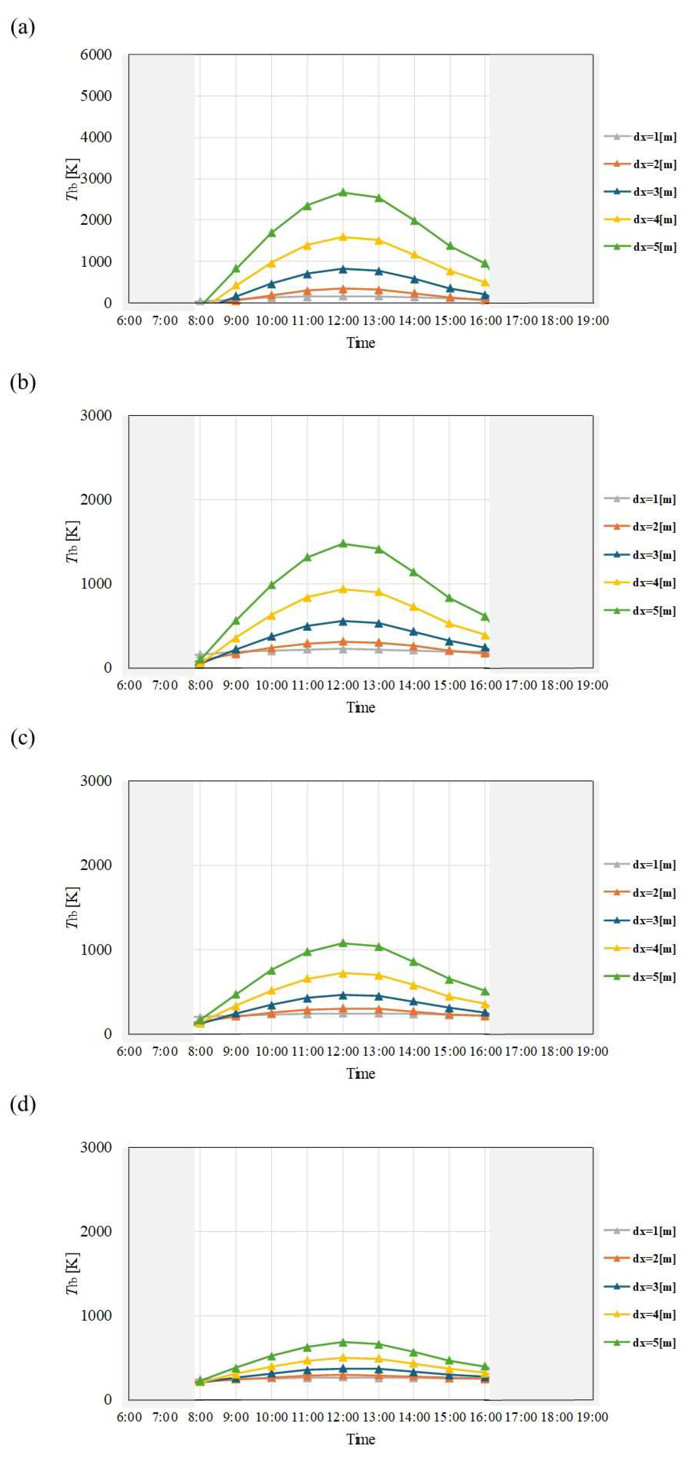
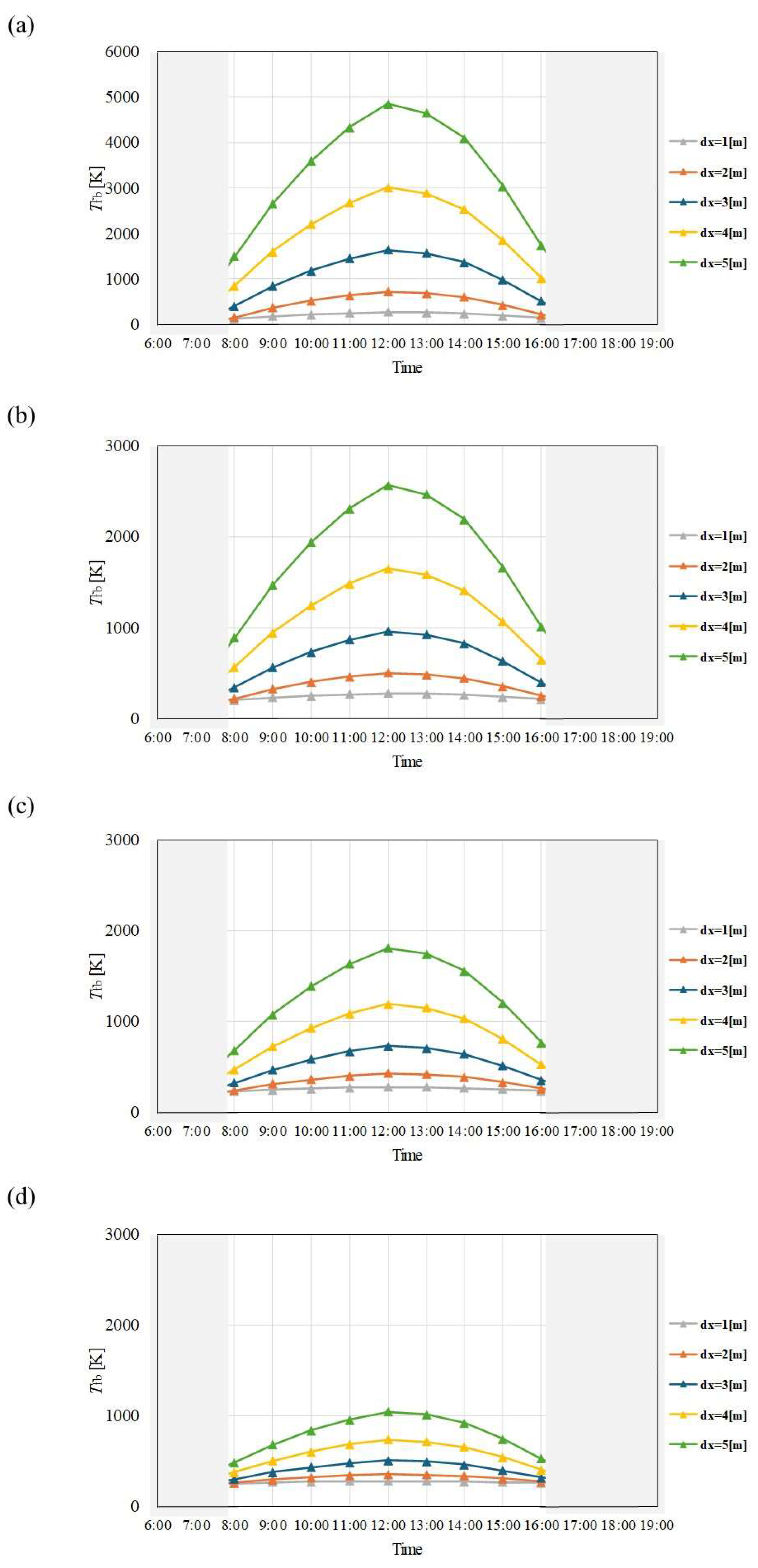
Figure 4.
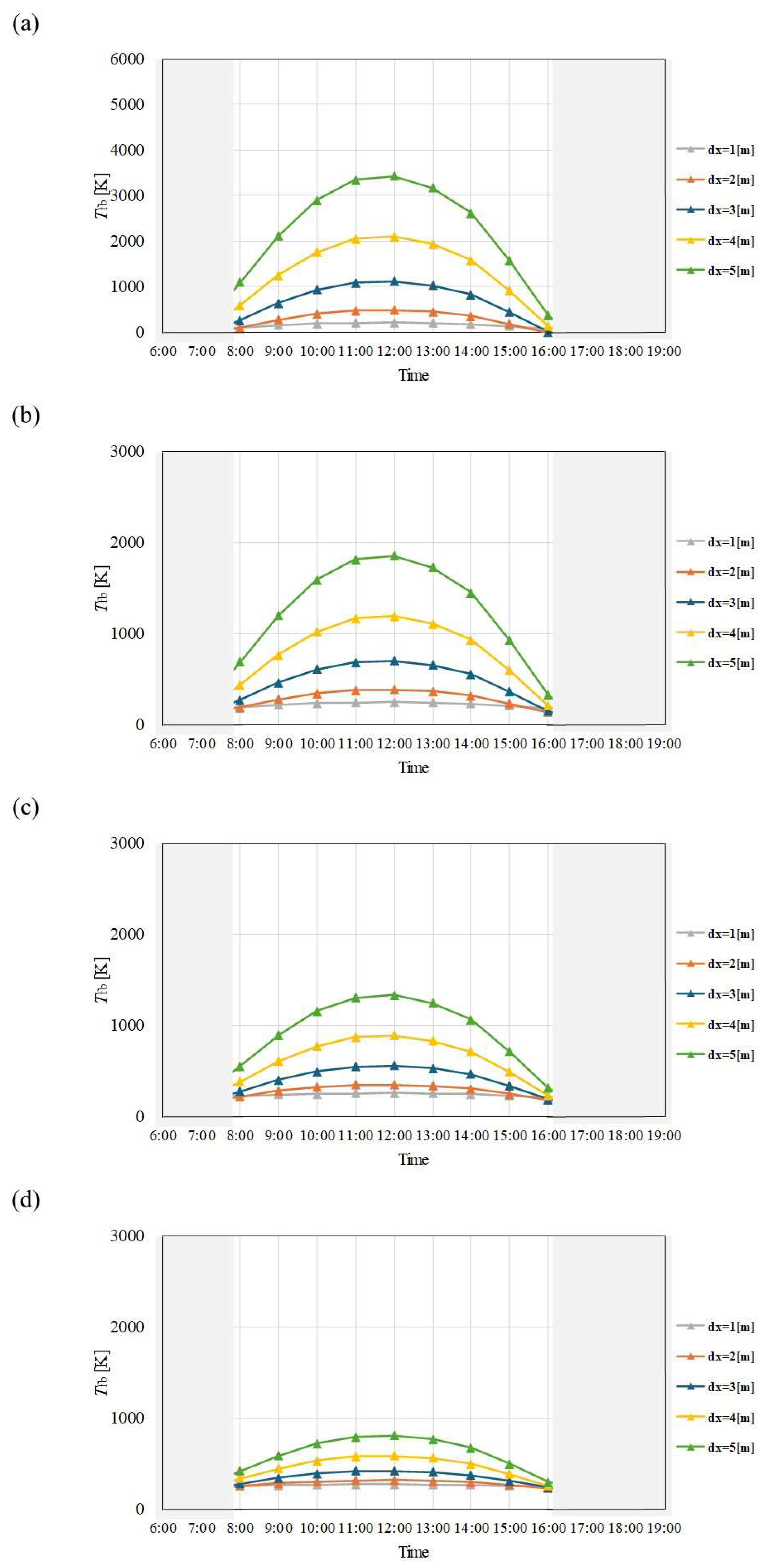
Comparison of change of Tfb with time among different dx and m in January. ((a): m = 0.005kg/s, (b): m = 0.010 kg/s, (c): m = 0.015 kg/s, (d): m = 0.030 kg/s).
Figure 4.
Comparison of change of Tfb with time among different dx and m in January. ((a): m = 0.005kg/s, (b): m = 0.010 kg/s, (c): m = 0.015 kg/s, (d): m = 0.030 kg/s).
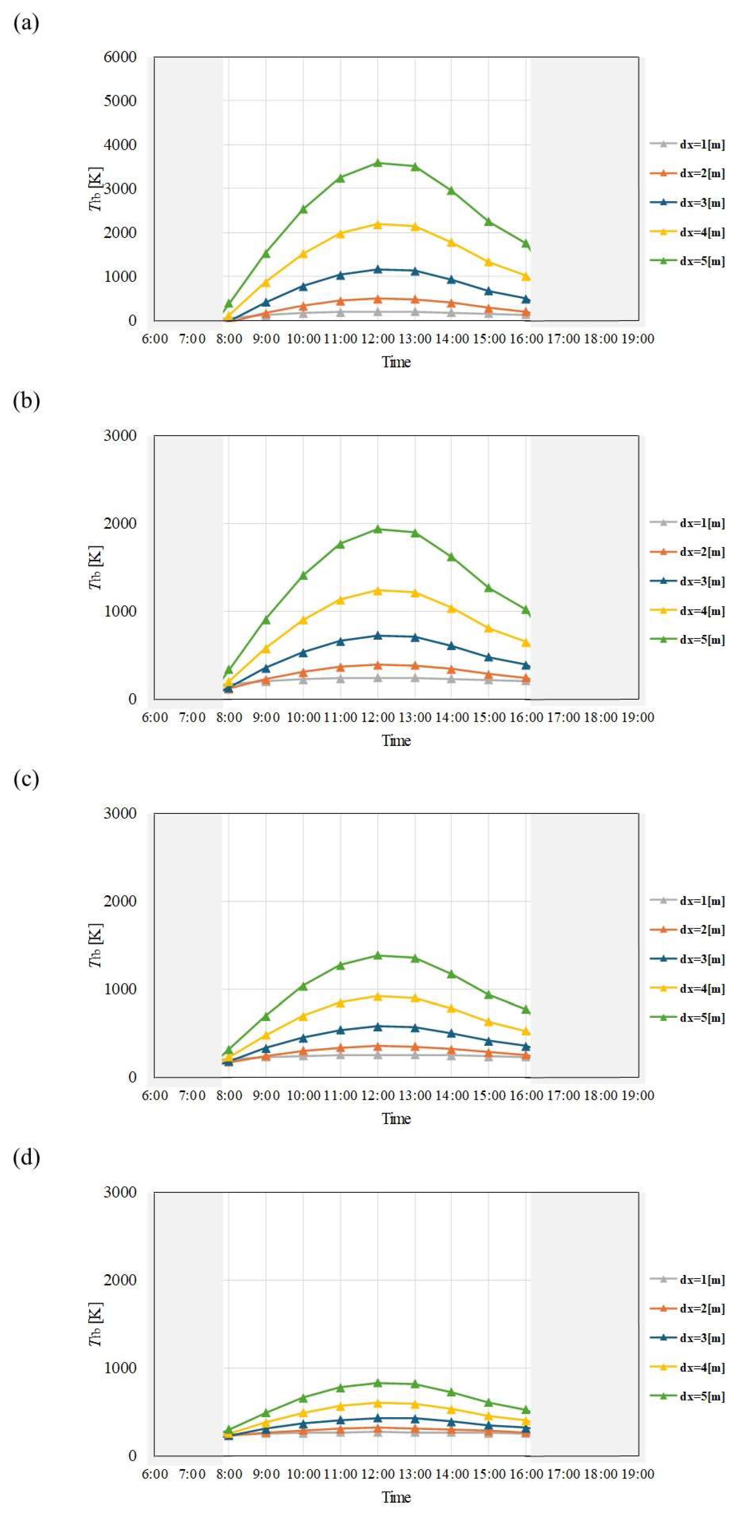
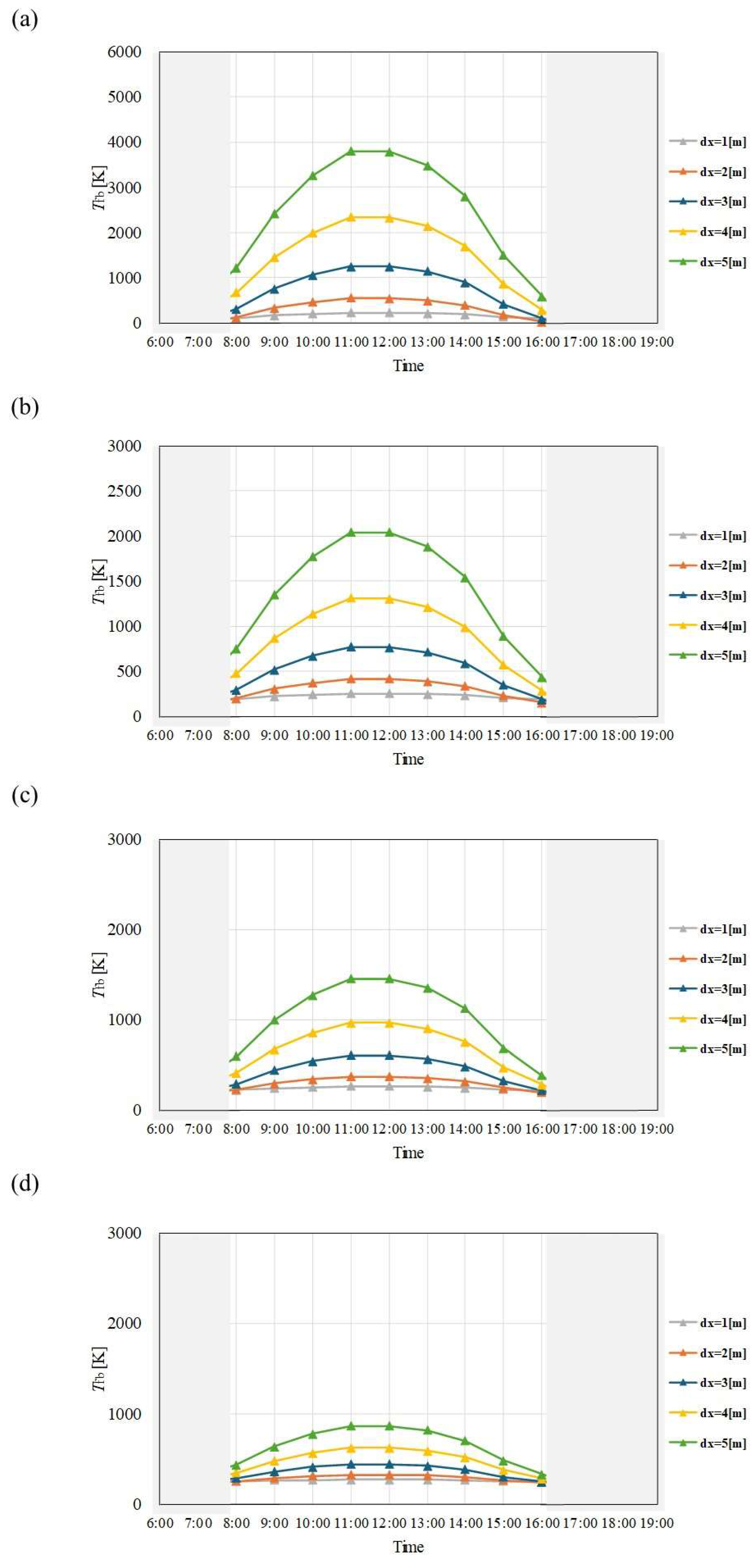
Figure 5.
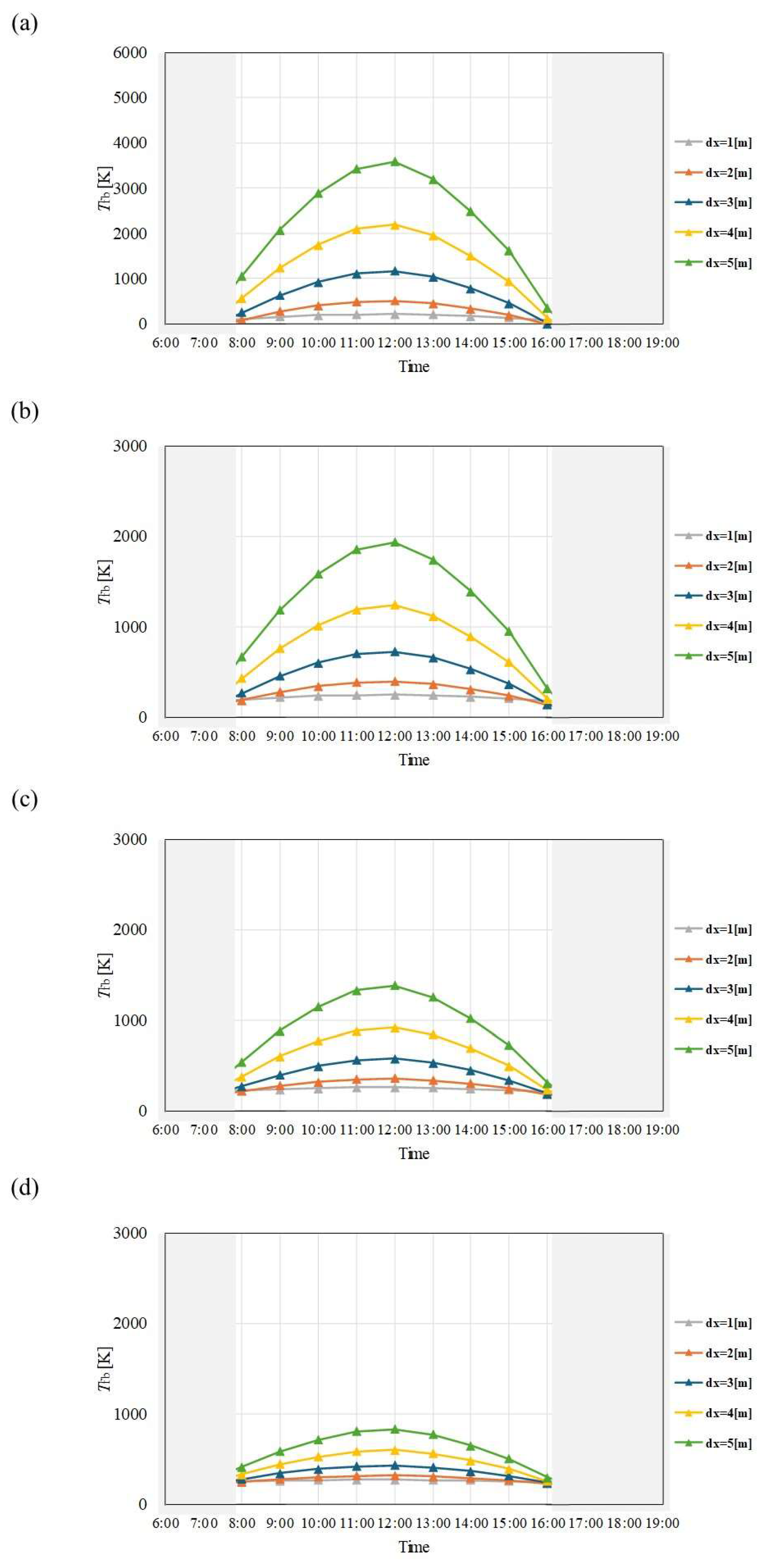
Comparison of change of Tfb with time among different dx and m in February. ((a): m = 0.005kg/s, (b): m = 0.010 kg/s, (c): m = 0.015 kg/s, (d): m = 0.030 kg/s).
Figure 5.
Comparison of change of Tfb with time among different dx and m in February. ((a): m = 0.005kg/s, (b): m = 0.010 kg/s, (c): m = 0.015 kg/s, (d): m = 0.030 kg/s).
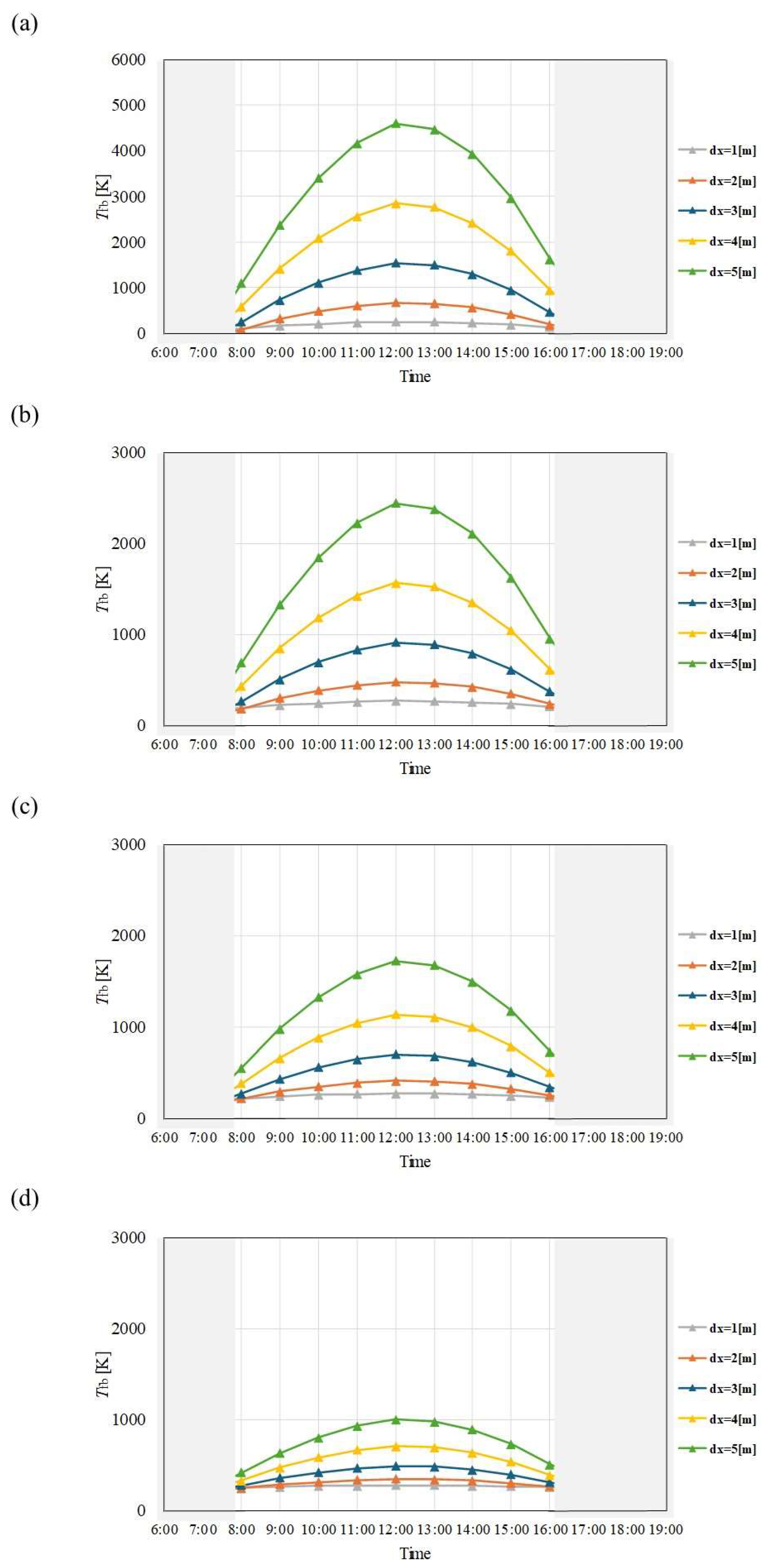
Figure 6.
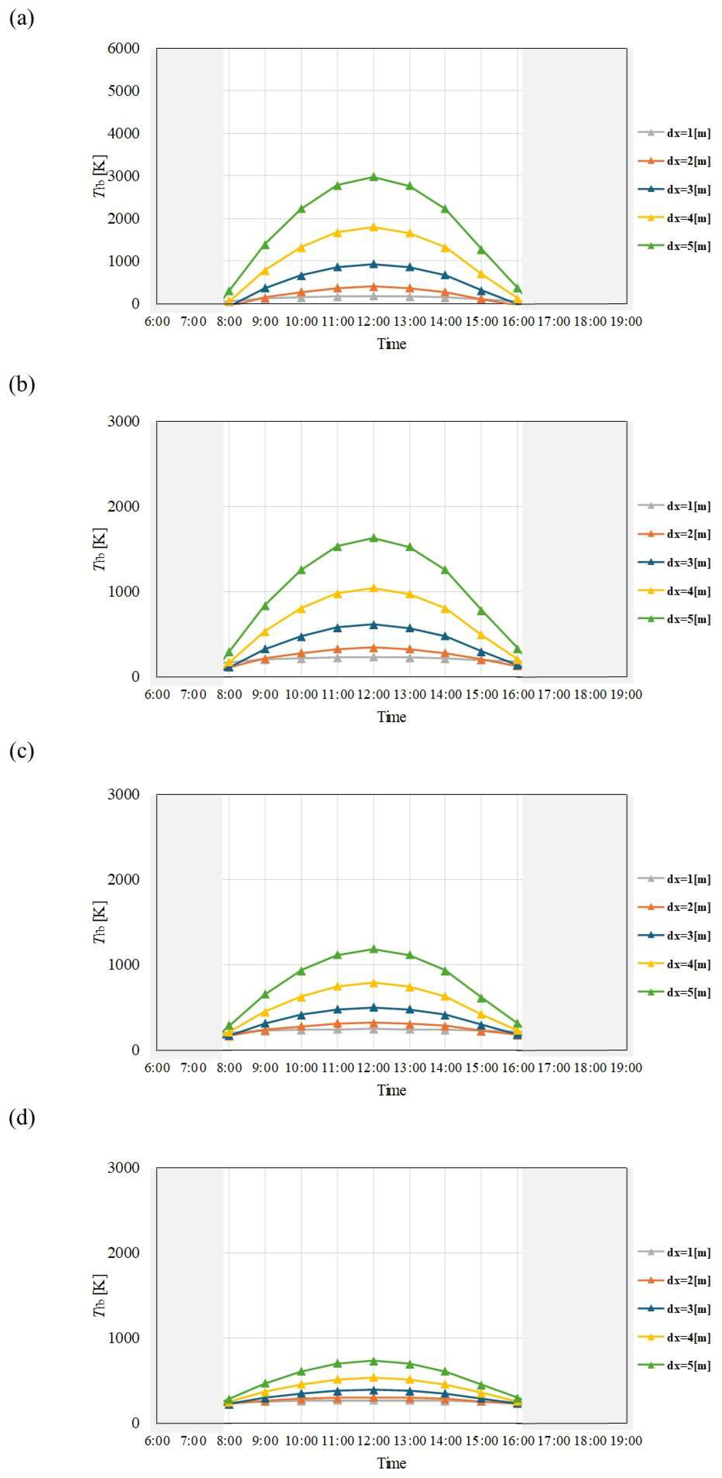
Comparison of change of Tfb with time among different dx and m in March. ((a): m = 0.005kg/s, (b): m = 0.010 kg/s, (c): m = 0.015 kg/s, (d): m = 0.030 kg/s).
Figure 6.
Comparison of change of Tfb with time among different dx and m in March. ((a): m = 0.005kg/s, (b): m = 0.010 kg/s, (c): m = 0.015 kg/s, (d): m = 0.030 kg/s).
Figure 7.
Comparison of change of Tfb with time among different dx and m in April. ((a): m = 0.005kg/s, (b): m = 0.010 kg/s, (c): m = 0.015 kg/s, (d): m = 0.030 kg/s).
Figure 7.
Comparison of change of Tfb with time among different dx and m in April. ((a): m = 0.005kg/s, (b): m = 0.010 kg/s, (c): m = 0.015 kg/s, (d): m = 0.030 kg/s).
Figure 8.
Comparison of change of Tfb with time among different dx and m in May. ((a): m = 0.005kg/s, (b): m = 0.010 kg/s, (c): m = 0.015 kg/s, (d): m = 0.030 kg/s).
Figure 8.
Comparison of change of Tfb with time among different dx and m in May. ((a): m = 0.005kg/s, (b): m = 0.010 kg/s, (c): m = 0.015 kg/s, (d): m = 0.030 kg/s).
Figure 9.
Comparison of change of Tfb with time among different dx and m in June. ((a): m = 0.005kg/s, (b): m = 0.010 kg/s, (c): m = 0.015 kg/s, (d): m = 0.030 kg/s).
Figure 9.
Comparison of change of Tfb with time among different dx and m in June. ((a): m = 0.005kg/s, (b): m = 0.010 kg/s, (c): m = 0.015 kg/s, (d): m = 0.030 kg/s).
Figure 10.
Comparison of change of Tfb with time among different dx and m in July. ((a): m = 0.005kg/s, (b): m = 0.010 kg/s, (c): m = 0.015 kg/s, (d): m = 0.030 kg/s).
Figure 10.
Comparison of change of Tfb with time among different dx and m in July. ((a): m = 0.005kg/s, (b): m = 0.010 kg/s, (c): m = 0.015 kg/s, (d): m = 0.030 kg/s).
Figure 11.
Comparison of change of Tfb with time among different dx and m in August. ((a): m = 0.005kg/s, (b): m = 0.010 kg/s, (c): m = 0.015 kg/s, (d): m = 0.030 kg/s).
Figure 11.
Comparison of change of Tfb with time among different dx and m in August. ((a): m = 0.005kg/s, (b): m = 0.010 kg/s, (c): m = 0.015 kg/s, (d): m = 0.030 kg/s).
Figure 12.
Comparison of change of Tfb with time among different dx and m in September. ((a): m = 0.005kg/s, (b): m = 0.010 kg/s, (c): m = 0.015 kg/s, (d): m = 0.030 kg/s).
Figure 12.
Comparison of change of Tfb with time among different dx and m in September. ((a): m = 0.005kg/s, (b): m = 0.010 kg/s, (c): m = 0.015 kg/s, (d): m = 0.030 kg/s).
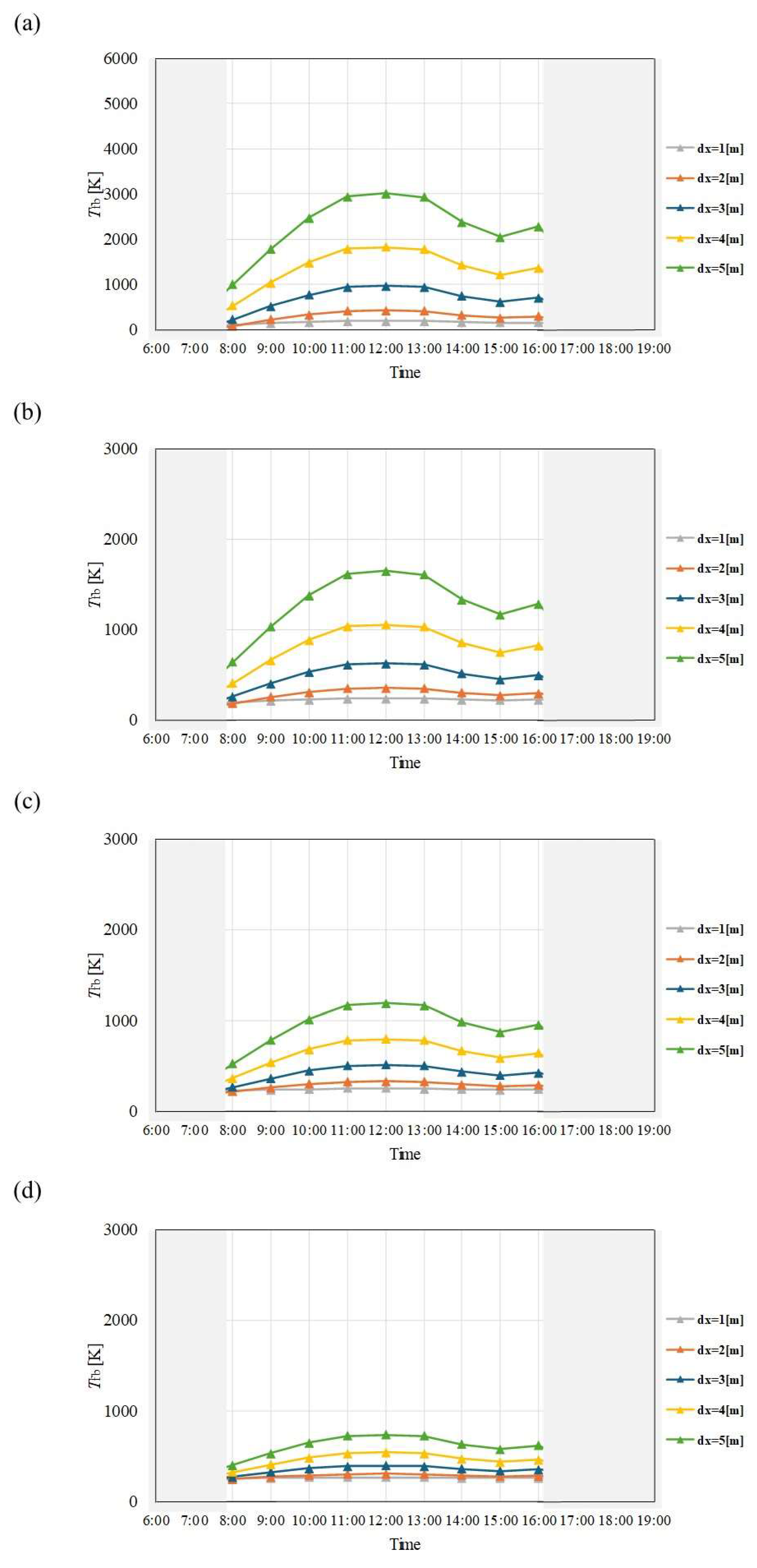
Figure 13.
Comparison of change of Tfb with time among different dx and m in October. ((a): m = 0.005kg/s, (b): m = 0.010 kg/s, (c): m = 0.015 kg/s, (d): m = 0.030 kg/s).
Figure 13.
Comparison of change of Tfb with time among different dx and m in October. ((a): m = 0.005kg/s, (b): m = 0.010 kg/s, (c): m = 0.015 kg/s, (d): m = 0.030 kg/s).
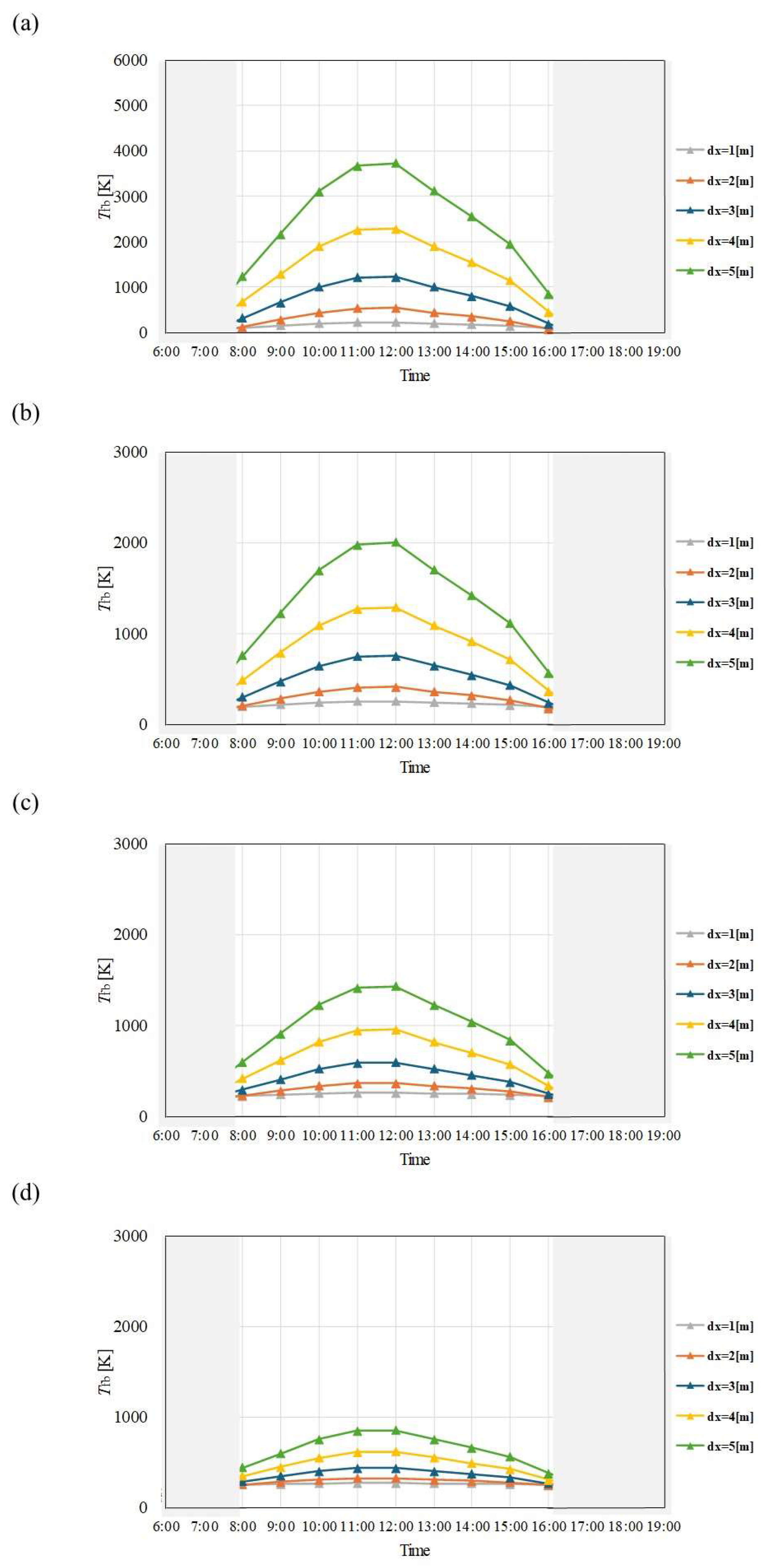
Figure 14.
Comparison of change of Tfb with time among different dx and m in November. ((a): m = 0.005kg/s, (b): m = 0.010 kg/s, (c): m = 0.015 kg/s, (d): m = 0.030 kg/s).
Figure 14.
Comparison of change of Tfb with time among different dx and m in November. ((a): m = 0.005kg/s, (b): m = 0.010 kg/s, (c): m = 0.015 kg/s, (d): m = 0.030 kg/s).
Figure 15.
Comparison of change of Tfb with time among different dx and m in December. ((a): m = 0.005kg/s, (b): m = 0.010 kg/s, (c): m = 0.015 kg/s, (d): m = 0.030 kg/s).
Figure 15.
Comparison of change of Tfb with time among different dx and m in December. ((a): m = 0.005kg/s, (b): m = 0.010 kg/s, (c): m = 0.015 kg/s, (d): m = 0.030 kg/s).
Table 1.
The physical properties which are adopted in this study [
5,
16,
21].
Table 1.
The physical properties which are adopted in this study [
5,
16,
21].
| Property |
Value |
Information |
|
α [-] |
0.94 |
- |
|
τ [-] |
0.94 |
- |
|
εt [-] |
0.9 |
- |
|
c [J/(kg・K)] |
1.335 |
for CH4:CO2 = 1.5:1 |
|
σ [W/(m2・K4)] |
5.67×10⁻⁸
|
Stefan-Boltzmann coefficient |
|
εg [-] |
0.94 |
Glass smooth surface |
|
ka [W/(m・K)] |
0.0257 |
Surrounding air |
|
ρa [kg/m3] |
1.166 |
Surrounding air |
|
μa [Pa・s] |
1.82×10⁻⁵
|
Surrounding air |
|
Cp,a [J/(kg・K)] |
1006 |
Surrounding air |
|
kt [W/(m・K)] |
16 |
Stainless steel |
|
Kg [W/(m・K)] |
1.3 |
Quartz glass |
Table 2.
Climate data of I, ua and Ta in Kolkata, India in January.
Table 2.
Climate data of I, ua and Ta in Kolkata, India in January.
| Time |
I [MJ/m2] |
ua [m/s] |
Ta [K] |
| 7:00 |
0.087 |
0.258 |
287.02 |
| 8:00 |
0.498 |
0.323 |
287.02 |
| 9:00 |
0.877 |
1.000 |
294.94 |
| 10:00 |
1.271 |
1.000 |
294.94 |
| 11:00 |
1.576 |
1.000 |
294.94 |
| 12:00 |
1.725 |
1.000 |
294.94 |
| 13:00 |
1.666 |
1.000 |
294.94 |
| 14:00 |
1.413 |
0.935 |
294.94 |
| 15:00 |
1.134 |
0.194 |
293.85 |
| 16:00 |
0.935 |
0.194 |
293.85 |
| 17:00 |
0.389 |
0.194 |
293.85 |
| 18:00 |
0.003 |
0.194 |
293.85 |
Table 3.
Climate data of I, ua and Ta in Kolkata, India in February.
Table 3.
Climate data of I, ua and Ta in Kolkata, India in February.
| Time |
I [MJ/m2] |
ua [m/s] |
Ta [K] |
| 7:00 |
0.162 |
0.214 |
289.65 |
| 8:00 |
0.700 |
0.214 |
289.65 |
| 9:00 |
1.173 |
0.214 |
299.87 |
| 10:00 |
1.674 |
0.964 |
299.87 |
| 11:00 |
1.966 |
0.964 |
299.87 |
| 12:00 |
2.124 |
0.964 |
299.87 |
| 13:00 |
2.085 |
0.964 |
299.87 |
| 14:00 |
1.830 |
0.964 |
299.87 |
| 15:00 |
1.508 |
0.214 |
298.80 |
| 16:00 |
1.282 |
0.214 |
298.80 |
| 17:00 |
0.660 |
0.214 |
298.80 |
| 18:00 |
0.090 |
0.214 |
298.80 |
Table 4.
Climate data of I, ua and Ta in Kolkata, India in March.
Table 4.
Climate data of I, ua and Ta in Kolkata, India in March.
| Time |
I [MJ/m2] |
ua [m/s] |
Ta [K] |
| 7:00 |
0.406 |
0.548 |
295.34 |
| 8:00 |
1.000 |
0.548 |
295.34 |
| 9:00 |
1.534 |
1.065 |
304.23 |
| 10:00 |
2.012 |
1.065 |
304.23 |
| 11:00 |
2.364 |
1.065 |
304.23 |
| 12:00 |
2.565 |
1.065 |
304.23 |
| 13:00 |
2.505 |
1.065 |
304.23 |
| 14:00 |
2.255 |
1.065 |
304.23 |
| 15:00 |
1816 |
0.581 |
303.07 |
| 16:00 |
1.199 |
0.581 |
303.07 |
| 17:00 |
0.681 |
0.581 |
303.07 |
| 18:00 |
0.108 |
0.581 |
303.07 |
Table 5.
Climate data of I, ua and Ta in Kolkata, India in April.
Table 5.
Climate data of I, ua and Ta in Kolkata, India in April.
| Time |
I [MJ/m2] |
ua [m/s] |
Ta [K] |
| 7:00 |
0.643 |
0.867 |
298.37 |
| 8:00 |
1.163 |
0.867 |
298.37 |
| 9:00 |
1.657 |
1.600 |
305.65 |
| 10:00 |
2.092 |
1.600 |
305.65 |
| 11:00 |
2.433 |
1.600 |
305.65 |
| 12:00 |
2.672 |
1.600 |
305.65 |
| 13:00 |
2.581 |
1.600 |
305.65 |
| 14:00 |
2.323 |
1.600 |
305.65 |
| 15:00 |
1.844 |
1.333 |
304.17 |
| 16:00 |
1.239 |
1.333 |
304.17 |
| 17:00 |
0.744 |
1.333 |
304.17 |
| 18:00 |
0.158 |
1.333 |
304.17 |
Table 6.
Climate data of I, ua and Ta in Kolkata, India in May.
Table 6.
Climate data of I, ua and Ta in Kolkata, India in May.
| Time |
I [MJ/m2] |
ua [m/s] |
Ta [K] |
| 7:00 |
0.744 |
0.355 |
299.41 |
| 8:00 |
1.266 |
0.355 |
299.41 |
| 9:00 |
1.771 |
1.290 |
306.59 |
| 10:00 |
2.223 |
1.290 |
306.59 |
| 11:00 |
2.555 |
1.290 |
306.59 |
| 12:00 |
2.684 |
1.290 |
306.59 |
| 13:00 |
2.555 |
1.290 |
306.59 |
| 14:00 |
2.241 |
1.290 |
306.59 |
| 15:00 |
1.786 |
1.613 |
304.49 |
| 16:00 |
1.150 |
1.613 |
304.49 |
| 17:00 |
0.517 |
1.613 |
304.49 |
| 18:00 |
0.184 |
1.613 |
304.49 |
Table 7.
Climate data of I, ua and Ta in Kolkata, India in June.
Table 7.
Climate data of I, ua and Ta in Kolkata, India in June.
| Time |
I [MJ/m2] |
ua [m/s] |
Ta [K] |
| 7:00 |
0.651 |
1.033 |
300.15 |
| 8:00 |
1.029 |
1.033 |
300.15 |
| 9:00 |
1.552 |
1.367 |
305.26 |
| 10:00 |
1.939 |
1.367 |
305.26 |
| 11:00 |
2.191 |
1.367 |
305.26 |
| 12:00 |
2.187 |
1.367 |
305.26 |
| 13:00 |
2.046 |
1.367 |
305.26 |
| 14:00 |
1.729 |
1.367 |
305.26 |
| 15:00 |
1.138 |
1.200 |
302.89 |
| 16:00 |
0.722 |
1.200 |
302.89 |
| 17:00 |
0.302 |
1.200 |
302.89 |
| 18:00 |
0.133 |
1.200 |
302.89 |
Table 8.
Climate data of I, ua and Ta in Kolkata, India in July.
Table 8.
Climate data of I, ua and Ta in Kolkata, India in July.
| Time |
I [MJ/m2] |
ua [m/s] |
Ta [K] |
| 7:00 |
0.556 |
0.484 |
300.25 |
| 8:00 |
0.926 |
0.484 |
300.25 |
| 9:00 |
1.260 |
1.452 |
304.60 |
| 10:00 |
1.579 |
1.452 |
304.60 |
| 11:00 |
1.796 |
1.452 |
304.60 |
| 12:00 |
1.828 |
1.452 |
304.60 |
| 13:00 |
1.792 |
1.452 |
304.60 |
| 14:00 |
1.538 |
1.452 |
304.60 |
| 15:00 |
1.390 |
1.097 |
303.29 |
| 16:00 |
1.504 |
1.097 |
303.29 |
| 17:00 |
0.997 |
1.097 |
303.29 |
| 18:00 |
0.454 |
1.097 |
303.29 |
Table 9.
Climate data of I, ua and Ta in Kolkata, India in August.
Table 9.
Climate data of I, ua and Ta in Kolkata, India in August.
| Time |
I [MJ/m2] |
ua [m/s] |
Ta [K] |
| 7:00 |
0.586 |
0.645 |
300.31 |
| 8:00 |
1.037 |
2.032 |
300.31 |
| 9:00 |
1.434 |
2.032 |
305.28 |
| 10:00 |
1.871 |
2.032 |
305.28 |
| 11:00 |
2.133 |
2.032 |
305.28 |
| 12:00 |
2.155 |
2.032 |
305.28 |
| 13:00 |
1.874 |
2.032 |
305.28 |
| 14:00 |
1.614 |
2.032 |
305.28 |
| 15:00 |
1.346 |
1.323 |
302.75 |
| 16:00 |
0.844 |
1.323 |
302.75 |
| 17:00 |
0.444 |
1.323 |
302.75 |
| 18:00 |
0.143 |
1.323 |
302.75 |
Table 10.
Climate data of I, ua and Ta in Kolkata, India in September.
Table 10.
Climate data of I, ua and Ta in Kolkata, India in September.
| Time |
I [MJ/m2] |
ua [m/s] |
Ta [K] |
| 7:00 |
0.518 |
0.333 |
299.56 |
| 8:00 |
0.972 |
0.333 |
299.56 |
| 9:00 |
1.409 |
1.267 |
304.88 |
| 10:00 |
1.775 |
1.267 |
304.88 |
| 11:00 |
1.981 |
1.267 |
304.88 |
| 12:00 |
2.019 |
1.267 |
304.88 |
| 13:00 |
1.901 |
1.267 |
304.88 |
| 14:00 |
1.645 |
1.267 |
304.88 |
| 15:00 |
1.178 |
1.033 |
302.16 |
| 16:00 |
0.622 |
1.033 |
302.16 |
| 17:00 |
0.338 |
1.033 |
302.16 |
| 18:00 |
0.040 |
1.033 |
302.16 |
Table 11.
Climate data of I, ua and Ta in Kolkata, India in October.
Table 11.
Climate data of I, ua and Ta in Kolkata, India in October.
| Time |
I [MJ/m2] |
ua [m/s] |
Ta [K] |
| 7:00 |
0.476 |
0.290 |
298.05 |
| 8:00 |
0.968 |
0.290 |
298.05 |
| 9:00 |
1.404 |
1.097 |
303.70 |
| 10:00 |
1.773 |
1.097 |
303.70 |
| 11:00 |
2.025 |
1.097 |
303.70 |
| 12:00 |
2.100 |
1.097 |
303.70 |
| 13:00 |
1.924 |
1.097 |
303.70 |
| 14:00 |
1.594 |
1.097 |
307.70 |
| 15:00 |
1.203 |
0.613 |
300.89 |
| 16:00 |
0.621 |
0.613 |
300.89 |
| 17:00 |
0.221 |
0.613 |
300.89 |
| 18:00 |
6.452×10⁻⁴
|
0.613 |
300.89 |
Table 12.
Climate data of I, ua and Ta in Kolkata, India in November.
Table 12.
Climate data of I, ua and Ta in Kolkata, India in November.
| Time |
I [MJ/m2] |
ua [m/s] |
Ta [K] |
| 7:00 |
0.340 |
0.333 |
292.90 |
| 8:00 |
0.863 |
0.367 |
292.90 |
| 9:00 |
1.345 |
1.133 |
301.10 |
| 10:00 |
1.749 |
1.133 |
301.10 |
| 11:00 |
2.038 |
1.133 |
301.10 |
| 12:00 |
2.075 |
1.133 |
301.10 |
| 13:00 |
1.942 |
1.133 |
301.10 |
| 14:00 |
1.613 |
1.100 |
301.10 |
| 15:00 |
1.119 |
0.267 |
297.87 |
| 16:00 |
0.680 |
0.267 |
297.87 |
| 17:00 |
0.158 |
0.267 |
297.87 |
| 18:00 |
0 |
3.597 |
297.87 |
Table 13.
Climate data of I, ua and Ta in Kolkata, India in December.
Table 13.
Climate data of I, ua and Ta in Kolkata, India in December.
| Time |
I [MJ/m2] |
ua [m/s] |
Ta [K] |
| 7:00 |
0.170 |
0.168 |
287.07 |
| 8:00 |
0.676 |
0.181 |
287.07 |
| 9:00 |
1.118 |
0.945 |
298.35 |
| 10:00 |
1.502 |
0.971 |
298.35 |
| 11:00 |
1.760 |
1.087 |
298.35 |
| 12:00 |
1.850 |
1.023 |
298.35 |
| 13:00 |
1.755 |
1.003 |
298.35 |
| 14:00 |
1.504 |
0.977 |
298.35 |
| 15:00 |
1.085 |
0.094 |
294.41 |
| 16:00 |
0.668 |
0.071 |
294.41 |
| 17:00 |
0.163 |
0.097 |
294.41 |
| 18:00 |
0 |
0.142 |
294.41 |
Table 15.
Comparison of GH2, PSOFC and N among different months for m = 0.010 kg/s at dx = 4 m.
Table 15.
Comparison of GH2, PSOFC and N among different months for m = 0.010 kg/s at dx = 4 m.
| |
GH2 [kg] |
PSOFC [Wh] |
N [-] |
| January |
7.46 |
137731 |
0.9 |
| February |
9.43 |
174163 |
1.2 |
| March |
11.94 |
220370 |
1.4 |
| April |
11.55 |
213261 |
1.4 |
| May |
11.94 |
220370 |
1.4 |
| June |
8.66 |
159946 |
1.0 |
| July |
11.94 |
220370 |
1.4 |
| August |
10.44 |
192824 |
1.2 |
| September |
8.66 |
159946 |
1.0 |
| October |
10.44 |
192824 |
1.2 |
| November |
8.66 |
159946 |
1.0 |
| December |
7.46 |
137731 |
0.9 |
| Total |
118.59 |
2189481 |
14.2 |
Table 16.
Comparison of GH2, PSOFC and N among different months for m = 0.015 kg/s at dx = 4 m.
Table 16.
Comparison of GH2, PSOFC and N among different months for m = 0.015 kg/s at dx = 4 m.
| |
GH2 [kg] |
PSOFC [Wh] |
N [-] |
| January |
6.71 |
123958 |
0.8 |
| February |
12.13 |
223924 |
1.6 |
| March |
15.67 |
289235 |
1.8 |
| April |
15.16 |
279905 |
1.8 |
| May |
15.67 |
289235 |
1.8 |
| June |
12.99 |
239919 |
1.6 |
| July |
13.43 |
247916 |
1.6 |
| August |
13.43 |
247916 |
1.6 |
| September |
12.99 |
239919 |
1.6 |
| October |
13.43 |
247916 |
1.6 |
| November |
10.83 |
199932 |
1.3 |
| December |
11.19 |
206597 |
1.3 |
| Total |
153.63 |
2836374 |
18.35 |
Table 17.
Comparison of GH2, PSOFC and N among different months for m = 0.030 kg/s at dx = 4 m.
Table 17.
Comparison of GH2, PSOFC and N among different months for m = 0.030 kg/s at dx = 4 m.
| |
GH2 [kg] |
PSOFC [Wh] |
N [-] |
| January |
0 |
0 |
0 |
| February |
4.04 |
74641 |
0.5 |
| March |
17.90 |
330555 |
2.1 |
| April |
21.66 |
399865 |
2.6 |
| May |
22.38 |
413194 |
2.6 |
| June |
8.66 |
159946 |
1.0 |
| July |
0 |
0 |
0 |
| August |
8.95 |
165277 |
1.0 |
| September |
0 |
0 |
0 |
| October |
4.48 |
82639 |
0.5 |
| November |
0 |
0 |
0 |
| December |
0 |
0 |
0 |
| Total |
88.07 |
1626116 |
10.48 |
