1. Introduction
Time delay, also known as "dead time" in automatic control theory, determines the impact of a reference signal on a control system's output after a specific duration. This is an inevitable situation in many control systems that operate in real time. A time delay in a control system can be caused by the sensors present in the system, the internal structure of the system, or the complexity with which the controller is designed. There are two different methods to evaluate this effect. The first method involves verbally discussing the control mechanisms, the control controller, and the time delay. The second and most important methodology is to calculate and analyse how time delays affect control mechanisms. For this reason, many studies have been carried out in the literature to mathematically explain the effect of time delay in control systems, and many different approaches have been developed about its mathematical analysis and effects. The characteristic equation of a closed-loop control system is written as a quasi-polynomial instead of a polynomial when there is a time delay in the control system algorithm. Polynomials have a finite number of roots, while polynomial equations have an infinite number of roots. This feature is one of the most important differences that separates the two characteristic structures. Given that the system's behaviour heavily depends on the positions of the closed loop poles, the system's time delay complicates both its analysis and its design. The Hermite-Biehler theorem, the Nyquist theorem, and the Walton-Marshall direct method are the most often used techniques in the literature for determining the stability of time-delayed control systems. The Hermite-Biehler Theorem, with its generalized version for polynomials, is unique among these techniques [
1]. The Nyquist theorem has served as the foundation for numerous investigations [
2,
3]. Numerous investigations have demonstrated the efficacy and power of the Walton-Marshall direct technique in determining the stability of control systems with time delays. Compared to the Nyquist theorem and the Hermite-Biehler theorem, this method is faster and more convenient. Furthermore, this method provides valuable insights into the effects of time delays on the number of poles in the right half s plane of an unstable control system and how this number may vary [
4]. The literature has conducted numerous studies on time-delay control designs. One of the studies on this subject focused on frequency shaping by taking advantage of the stabilizing properties of time delays [
5]. Another study proposed a new controller type that leverages the time delay effect [
6]. It has been stated that this control structure can replace the PD controller by performing a mean derivative action. The traditional P controller, equipped with a suitable time delay, provides fast responses to input changes and is insensitive to high-frequency noise. Researchers conducted a study to stabilize oscillatory systems, demonstrating that positive, delayed feedback stabilized the oscillatory system [
7]. This study demonstrates the stability of the closed-loop system using the Nyquist criterion across various delays. In another study on time-delayed systems in the literature, Niculescu and Michiels showed that time delay provides stabilization of linear systems, including integrator chains [
8]. Galip Ulusoy proposed a time-delayed control structure for single-input, single-output linear time-invariant systems [
9]. This control structure is known to enhance stability margins and decrease sensitivity. Another study demonstrated that the cascade control network enhances the control mechanism's performance, particularly when faced with unpredictable disturbances [
10]. The stability of the control system is improved in this study by using the cascade controller algorithm in a single machine power system that is linked to an infinite busbar that has a Static Synchronous Series Compensator (SSSC). The cascade control method has proven to perform better than standard control methods. The literature contains numerous studies on control of dual tank systems, a type of time-delayed system. The first of the recent studies is the adaptive-based control technique, which is especially sensitive to disturbances [
11]. The adaptable feature of the controller parameters in this study enabled excellent control performance, even in the face of undetermined system parameters and disturbances. The fractional order controller design is another control method [
12]. In this liquid level control study, system performance was increased by using a fractional order PI controller instead of the classical PI controller. Another study in the literature used the backstepping controller and the developed observer effect to prevent disruptive effects from occurring in the system [
13]. Additionally, researchers tested the system's performance by applying control techniques such as fuzzy logic-based PI control [
14] and genetic algorithm-based tuneable artificial neural network control [
15].
Another study used a control design to control a time-delayed double tank system in real time. This control design is known as a cascade proportional integral retarded (CPIR) controller. Initially, López built and tested this controller for DC servo motor position control [
16]. The suggested controller features an outer loop and an inner loop in a stepwise configuration. The inner loop, with its delayed algorithm structure, adjusts the angular velocity of the regulated DC servo motor, while the outer loop uses a proportional controller to modify the system's angular position. This controller has been able to achieve excellent position control under varying loads and disruptive effects, as well as eliminating overshoots that may occur during position changes. It is capable of monitoring the DC servo motor's angular velocity without the need for extra filters.
Different research suggests utilizing a fractional IMC filter PID control approach to improve the efficiency of cascade control systems that are frequently employed in chemical process industries [
17]. The suggested method enhances control performance, particularly in set point tracking, disturbance rejection, and noise handling, by incorporating a fractional order filter in the outer loop and completing thorough robustness and fragility evaluations. The study used an analytical methodology to create and fine-tune the controllers, streamlining the whole design process and reducing errors. The versatility of the fractional IMC filter and its ability to be applied to different process models demonstrate its potential for widespread industrial utilization.
A simple and effective control strategy for time-delayed unstable series cascade processes is also given in [
18]. By utilizing a PID controller with a second-order lead-lag filter in conjunction with an IMC controller, the proposed method simplifies the control design while ensuring robust performance and efficient disturbance rejection. The innovative use of an underdamped IMC filter configuration enhances the reset rate action, providing improved integral performance. Despite its advantages, the strategy's applicability to more complex or different types of processes remains limited, and its reliance on accurate process modelling is a potential drawback. Simulation studies validate the method's efficacy, but real-world testing is needed for a comprehensive evaluation.
A robust and efficient control strategy for unstable processes with time delay, leveraging a modified Smith predictor in a cascade control structure, was introduced in [
19]. While it simplifies controller design and enhances performance, especially in disturbance rejection and robustness, the practical implementation may still pose challenges and require careful handling of process model accuracy and overshoot issues.
Another paper underscores the limitations of conventional PI control in CAV systems and highlights the potential of advanced control strategies, particularly model-based approaches, to improve system performance [
20]. The proposed model-based cascade control method is positioned as a promising solution to overcome the challenges of thermal inertia and dynamic uncertainties in CAV air-conditioning systems, offering better control robustness and accuracy.
In [
21], simulations on double tanks have demonstrated that the genetic fuzzy cascade control method offers rapid adjustment speed, minimal overshoot, and excellent stability, thereby enhancing the automation level of the liquid level control system. Consequently, this control method offers efficient control performance for systems characterized by an unstable transfer function and a pure time delay. A separate work introduces comprehensive autotuning parameters for 2-DOF PI/PID controllers in a cascade control setup [
22]. The requirement for achieving the best possible performance in tracking and regulation modes has resulted in the adoption of the corresponding two degrees of freedom (2-DOF) version for the controllers. The autotuning algorithms for both the inner and outer loop controller parameters have effectively resolved the limitations associated with tuning a cascade control arrangement [
23].
This study aimed to design a robust and efficient controller that could precisely control the liquid level system. This controller is made to be resilient and adaptable to unknown loads and the unmodeled and/or unmodelable dynamics of nonlinear systems. To overcome these mentioned conditions, a cascade nonlinear proportional integral retarded (CNPIR) control design was used for the first time in the literature to control a double-tank liquid level system in real-time. The specified cascade controller has been employed to enhance robustness against disturbances and noise that may occur during the system's operation. Additionally, a systematic approach utilizes this controller, which fundamentally incorporates a time delay, to enhance the system's ability to increase position and velocity tracking precision, simplify system modelling, and resolve stability maintenance issues. Furthermore, it possesses a control structure that enhances system performance for modelling instabilities. This feature of the CNPIR technique, in contrast to the classical PI control technique, restructures the dynamic equations of the system under control within a specific framework, enabling the generation of appropriate control signals during the system's movement. In this manner, the system minimizes position and velocity errors. Finding a full and accurate dynamic model of the system and using it, especially in the CNPIR control method, leads to better control performance than traditional PI control, according to the results.
The following is the work's outline: The FF-PI, CPIR, and CNPIR control laws are defined in the next section, which also addresses closed-loop liquid-level system modelling concerns. Several results are reported later in the section on experimental results. A few closing thoughts and a list of topics that warrant more research complete this work.
2. Dynamic Model of Liquid Level and System Description
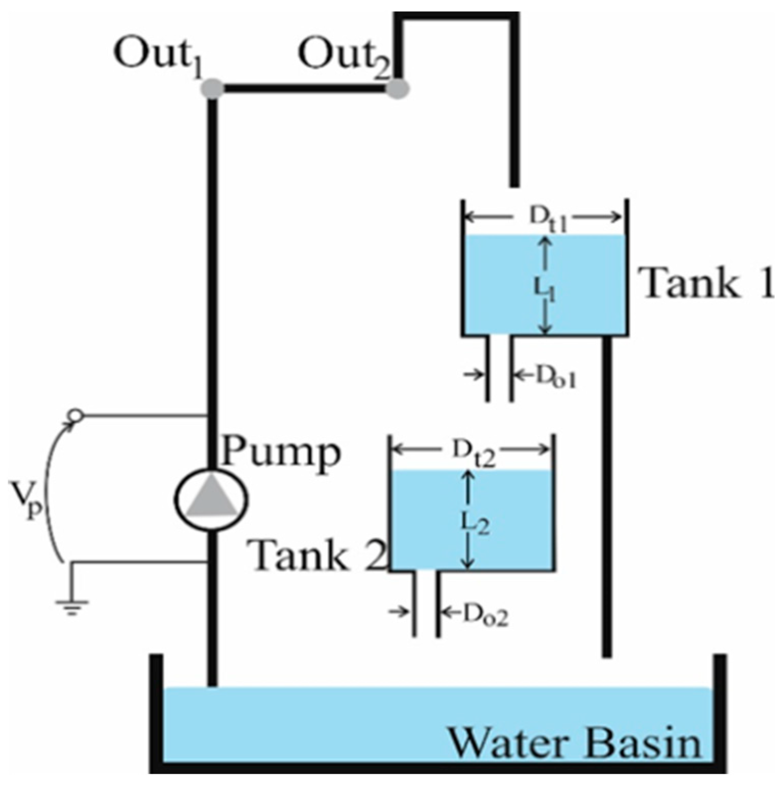
Figure 1 depicts the closed recirculating test system used for a connected tank. The system comprises two interconnected liquid tanks, an electrically operated pump, a level monitoring aperture at the bottom of each tank, and a pressure sensor. Tank 1 is supplied by the electric pump, and
Figure 1 shows how both liquid tanks are mounted on the front plate. Tank 2 receives the outflow from Tank 1. Two pressure-sensitive sensors, located at the base of each tank, measure the liquid levels in both reservoirs.
The mathematical basis of the interconnected tank system can be found in [
24]. The rate of change of the liquid level in each separate reservoir is as follows:
The variable
represents the liquid level in the reservoir, measured in centimetres.
represents the cross-sectional area of the reservoir, measured in square centimeters.
and
represent the inflow and outflow rates of the i-th tank, measured in cubic centimetres per second. The rate at which liquid flows into tank 1 is precisely proportional to the voltage that is applied to the pump. This means that as the voltage increases, the inflow rate into the tank also increases.
The constant
represents the pump's conversion factor in cubic centimetres per volt-second (
. The control input,
, also known as the voltage pump
in volts (
), is utilized to attain the desired levels in either tank 1 or tank 2 as follows;
The contributions of the cascade rule and the feedforward action are denoted by
, respectively, in Equation (3). Moreover, Equation (4) provides the outflow velocity from the orifice at the bottom of each unique tank using Bernoulli's law.
Next, using Equation (5), the outflow percentage of a separate liquid tank is calculated.
where
is the cross-sectional area of the outflow orifice (
) at the bottom of the
-th tank, and
is the gravitational acceleration (
). Tank 2's inflow is determined as follows;
Thus, the following mathematical expression for the liquid level in the connected tanks can be produced by applying the mass balance principle and Equations (1-6);
The steady-state pump voltage,
, that leads to the steady-state level,
, in reservoir 1 is determined by using Equation (7) when the system is at equilibrium (
). Equation (8) is employed to determine the value of
in reservoir 1 when the system is at equilibrium (
). This value represents the desired constant level in reservoir 2, referred to as the planned steady-state level. The relationships are specified in Equations (9) and (10).
Deviation variables can be defined by utilizing the operational range that corresponds to small departure voltages (
) and heights (
)
The cascade control is denoted by
. Thus, it is possible to translate the dynamic equations of Equation (7) and Equation (8) as follows:
The liquid level system's dynamic equations are nonlinear due to the characteristics of the pump and valve, as well as variations in the system's parameters, as shown by Equations (12) and (13). In order to execute the suggested cascade for the connected tank system, it is necessary to linearize the linked tank system model around the operational point
. Applying the first-order Taylor series approximation at the points (
and
)) to Equations (12) and (13) results in the following:
where,
After analysing the subsystem decomposition of Equation (14) and Equation (15), the task of regulating the level in Tank 2 (i.e., achieving set-point control of
) is established. In this particular context,
and
symbolize the output and input of the subsystem, respectively, as mentioned in Equation (15). In addition, the subsystems in Equations (14) and (15) are modelled as transfer functions, and the Laplace transforms of these equations are given in Equations (17) and (18) as follow;
where,
,
,
and
. It is evident that Equations (17) and (18) can be applied to both cascade and traditional PI.
Table 1 displays the parameters of the connected tank system.
2.1. Controller Design
In this section, the liquid level system has been subjected to a classical PI controller design with feedforward application in order to provide real-time position control. In order to improve the accuracy of controlling the liquid level system, a controller design called cascade nonlinear proportional integral retarded (CNPIR) has been developed. This design takes into consideration the dynamic models of the system.
2.1.1. Feed-Forward Proportional Integral Controller Design (FF-PI) Tank 1
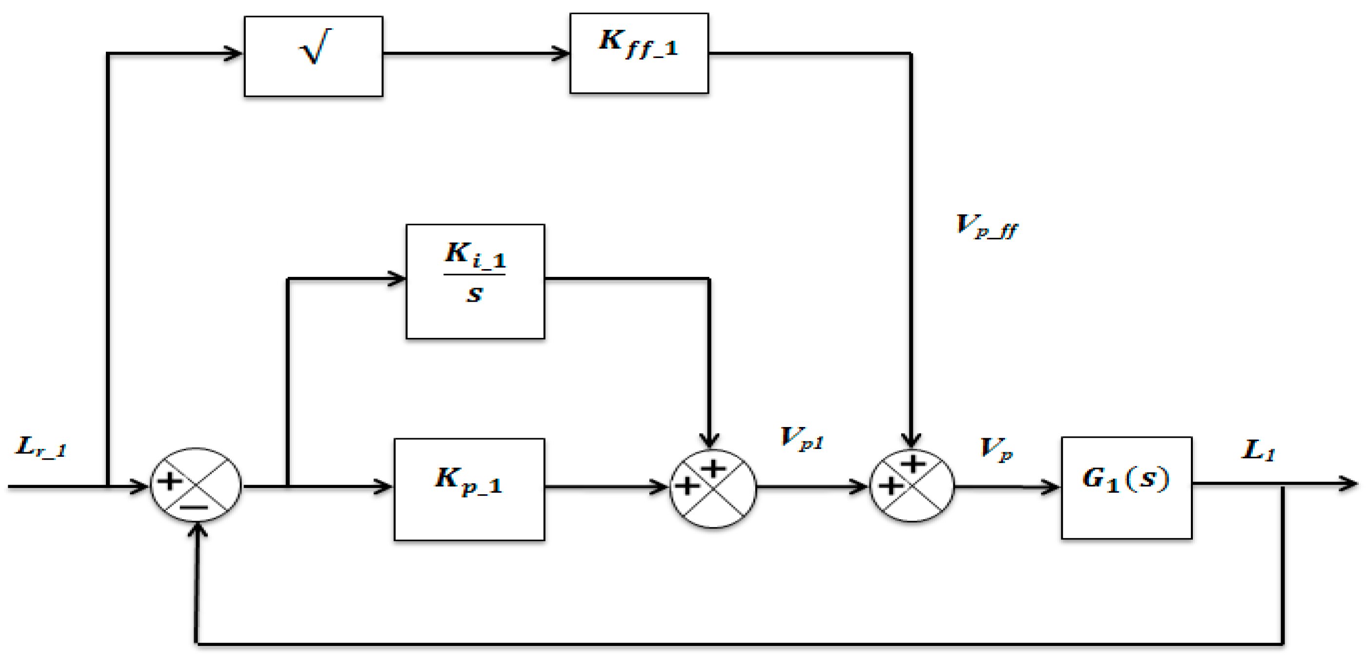
Feedforward action in process control technology counteracts the impact of the measured disturbance on the process output. In this situation, the feedforward action is used to counterbalance the water being taken out (due to gravity) through the orifices at the bottom outlets of Tank 1 and Tank 2. However, the effects of unaccounted dynamics and disturbances are addressed by the cascade proportional-integral controllers, which are designed to handle time delays. A control pump is specifically engineered to modulate the water level or elevation by means of electricity. The control structure at the beginning is a feedforward proportional-integral controller (FF-PI) as shown in
Figure 2.
For zero steady-state error, the water level in Tank 1 is controlled through a positive proportional-integral (PI) closed-loop scheme with the addition of feedforward action, as shown in
Figure 2. The mathematical equation for the voltage feedforward controller is presented in Equations (19) and (20) as follow;
While the feedforward action compensates for water withdrawal (due to gravity) through the bottom outlet of Tank 1, the PI controller compensates for dynamic disturbances. The transfer function of the feedforward PI control indicated in
Figure 2 can be expressed as in Equation (21).
After conducting the liquid level experiment in Tank 1 with the feedforward PI controller, the CNPIR controller was used, considering the system dynamics. Thus, both control structures were compared through real-time experiments.
2.1.2. Feed-Forward Proportional Integral Controller Design (FF-PI) Tank 2
The second tank, which is designed with a feedforward proportional-integral controller, is shown in
Figure 3. In the designed block diagram, the closed-loop transfer function, named
, represents the water level of the 1st tank and is mathematically expressed in Equation (22) as follow;
The feedforward effect is mathematically expressed by the following Equation (23):
The input signal for the liquid level in Tank 1,
, is equal to the sum of
, which is called the small increase in liquid height calculated by the proportional-integral (PI) controller, and
, which is obtained from the feedforward effect.
According to Equation (24), the desired liquid level control of the tank is achieved as a result of the feedforward effect and the values calculated by the PI controller. To calculate the transfer function of Tank 2, the output value of Tank 2 needs to be divided by the input value of Tank 1 as follows;
2.1.3. CPIR and CNPIR Controller Methods
In this section, the mathematical model and block structure of the time-delayed CPIR and CNPIR controllers are explained, considering the system dynamic model for the position control of the liquid level tank. Velocity measurements feed the Integral Retarded (IR) controller, which corresponds to the inner loop. Three parameters need to be adjusted: the gains
,
, and the time delay
. The outer loop is closed using a proportional controller with a gain of
and is supplied with position readings. Equation (26) defines the time-effective mathematical expression of the CPIR controller [
16].
Here,
represents the derivative of the output parameter, in other words, the change in liquid level for Tank 1 and Tank 2. The characteristic quasi-polynomial of the closed-loop system is directly obtained with the help of
Figure 3 and is presented in Equation (27). In
Figure 3, the reference input
represents the desired liquid level for Tank 1 and Tank 2, while
represents the output magnitude, i.e., the liquid level obtained for Tank 1 and Tank 2.
However, the quasi-polynomial expression of the inner velocity loop can be defined by Equation (28) as follow;
Figure 4 displays the closed-loop CNPIR controller. In this case, the CNPIR control law [
16] can be defined in its most general form by Equation (29) as follows;
The saturation function of CNPIR is shown in
Figure 4 and this function specified in Equation (29) is expressed by Equation (30) as follows;
Equation (29) defines
as the scaling factor. If the positional error
is small enough, the value of
does not exceed the saturation limitations, and both the outer and inner loops operate in conjunction. Therefore, the values of
and
nullify each other. If the positioning task results in a significant position error,
can be either 1 or -1. Here, the outer loop is disabled, and only the inner velocity loop functions. The system attains a steady velocity. When the position error diminishes, the saturation block functions within its linear range, causing both loops to become active once more. An advantage of the CPIR controller over the standard P-PI controller is its utilization of time delays, which effectively eliminates the need for velocity measurements. The second advantage is that the CPIR method does not use the finite differences method, thereby eliminating the deficiencies associated with high-pass filters. The initial design of the CPIR controller, which does not have a cascade structure, is called the Proportional Integral Retarded (PIR) controller. When a new outer loop is added to this PIR controller, the CPIR controller architecture is obtained. The CPIR controller has a notable advantage over the PIR controller in that the inner loop within the controller can function independently if the extra outer loop is disengaged. The addition of a saturation function (SAT) to the CPIR controller results in the formation of the Cascade Nonlinear Proportional Integral Retarded (CNPIR) controller design [
16]. Incorporating the saturation function into the controller architecture offers a notable benefit, especially in terms of mitigating overshoot in the system's response. For more detailed information on the tuning methodology for CNPIR, see reference [
16].
Figure 1.
The coupled-tank recirculating system.
Figure 1.
The coupled-tank recirculating system.
Figure 2.
Feedforward PI control block diagram for Tank-1 experiment.
Figure 2.
Feedforward PI control block diagram for Tank-1 experiment.
Figure 3.
Feedforward PI control block diagram for Tank-2 experiment.
Figure 3.
Feedforward PI control block diagram for Tank-2 experiment.
Figure 4.
CNPIR controller block diagram.
Figure 4.
CNPIR controller block diagram.
Figure 5.
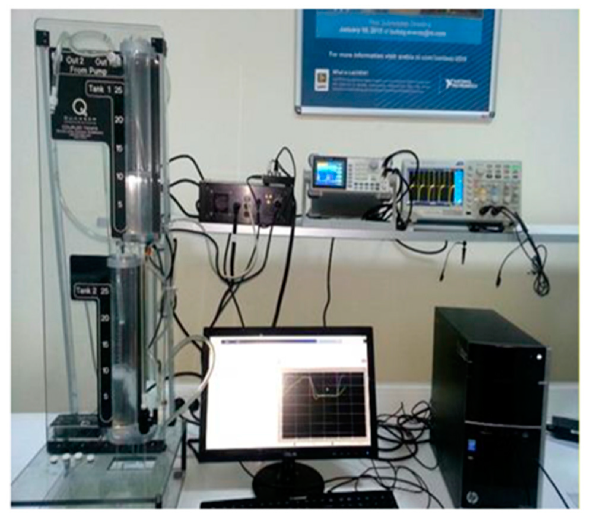
Quanser liquid level system where the experiments were carried out.
Figure 5.
Quanser liquid level system where the experiments were carried out.
Figure 6.
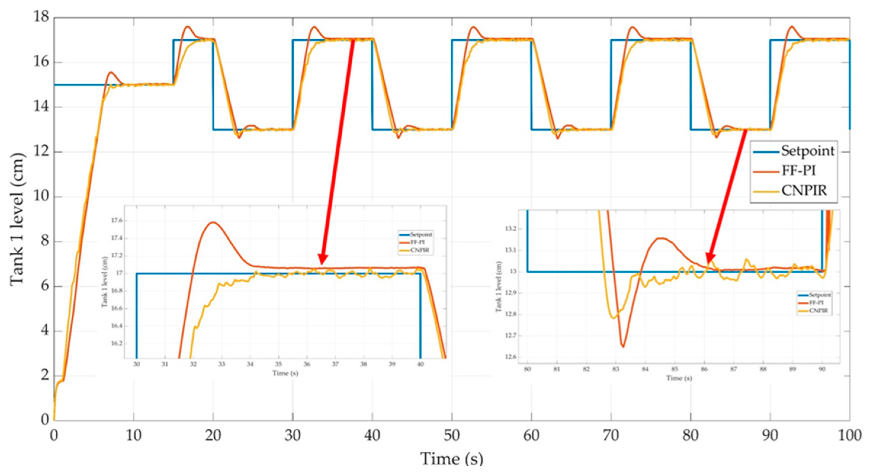
Control performances of the CNPIR and FF-PI controllers for Tank 1.
Figure 6.
Control performances of the CNPIR and FF-PI controllers for Tank 1.
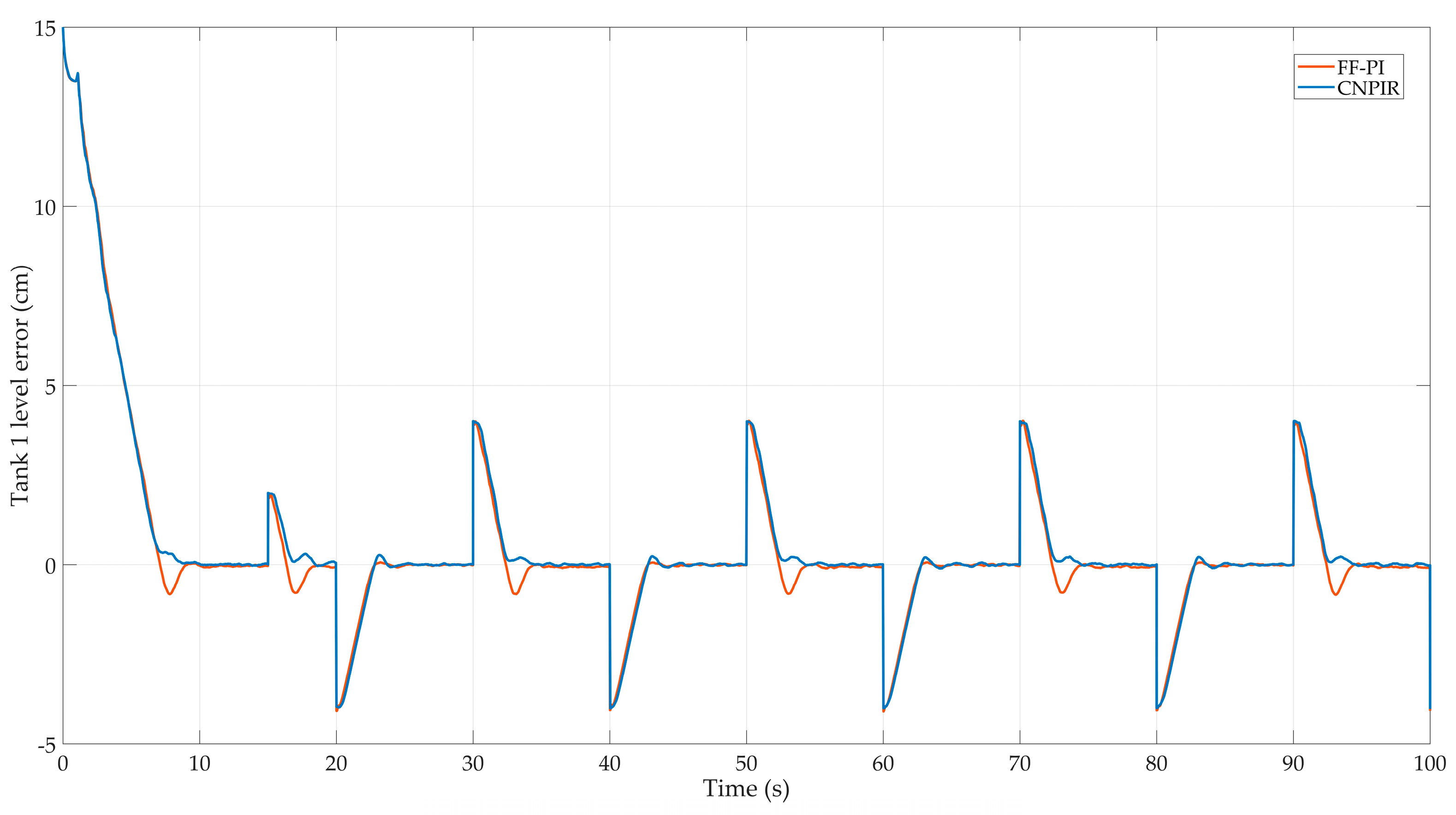
Figure 7.
Tracking error for Tank 1 configuration.
Figure 7.
Tracking error for Tank 1 configuration.
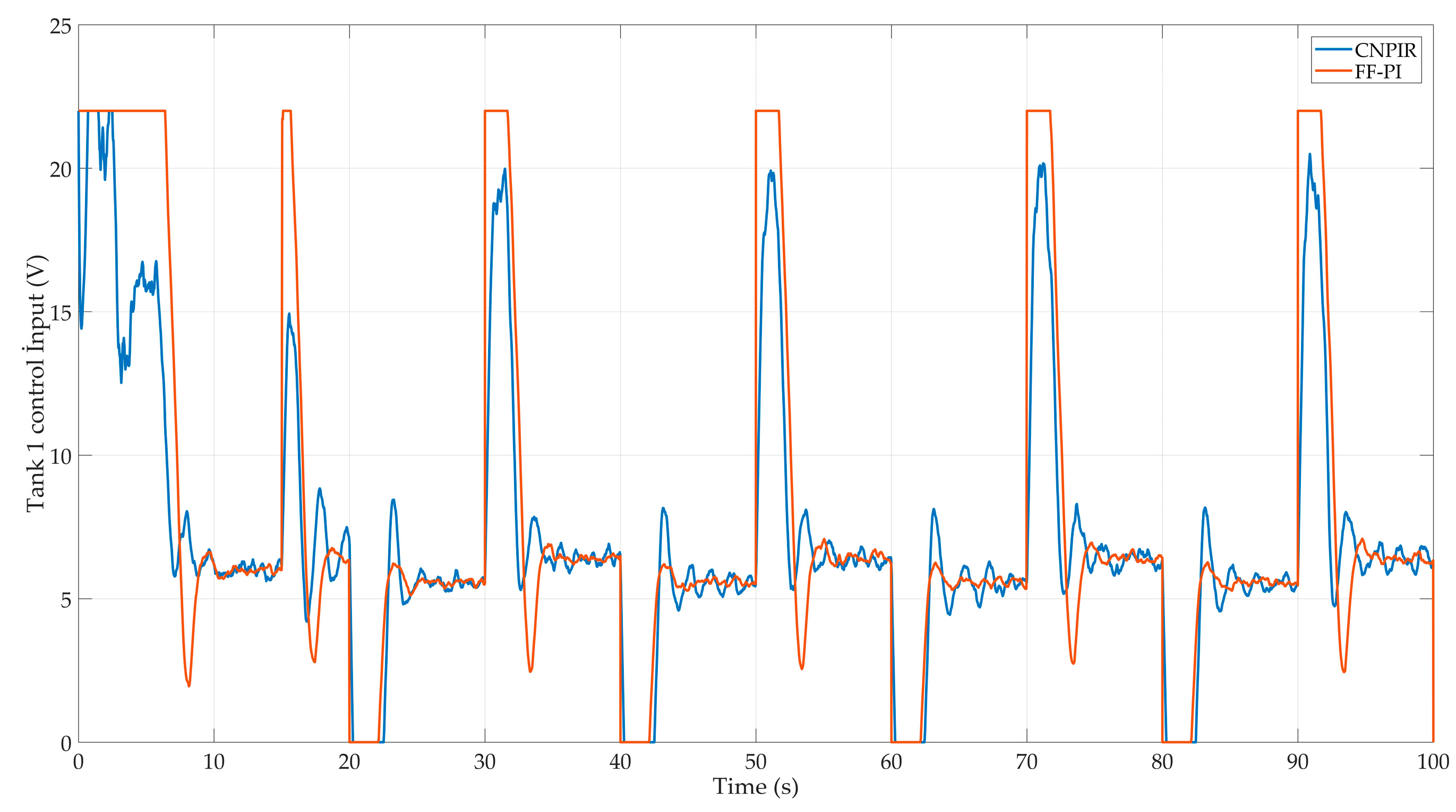
Figure 8.
Tank 1 level control signs.
Figure 8.
Tank 1 level control signs.
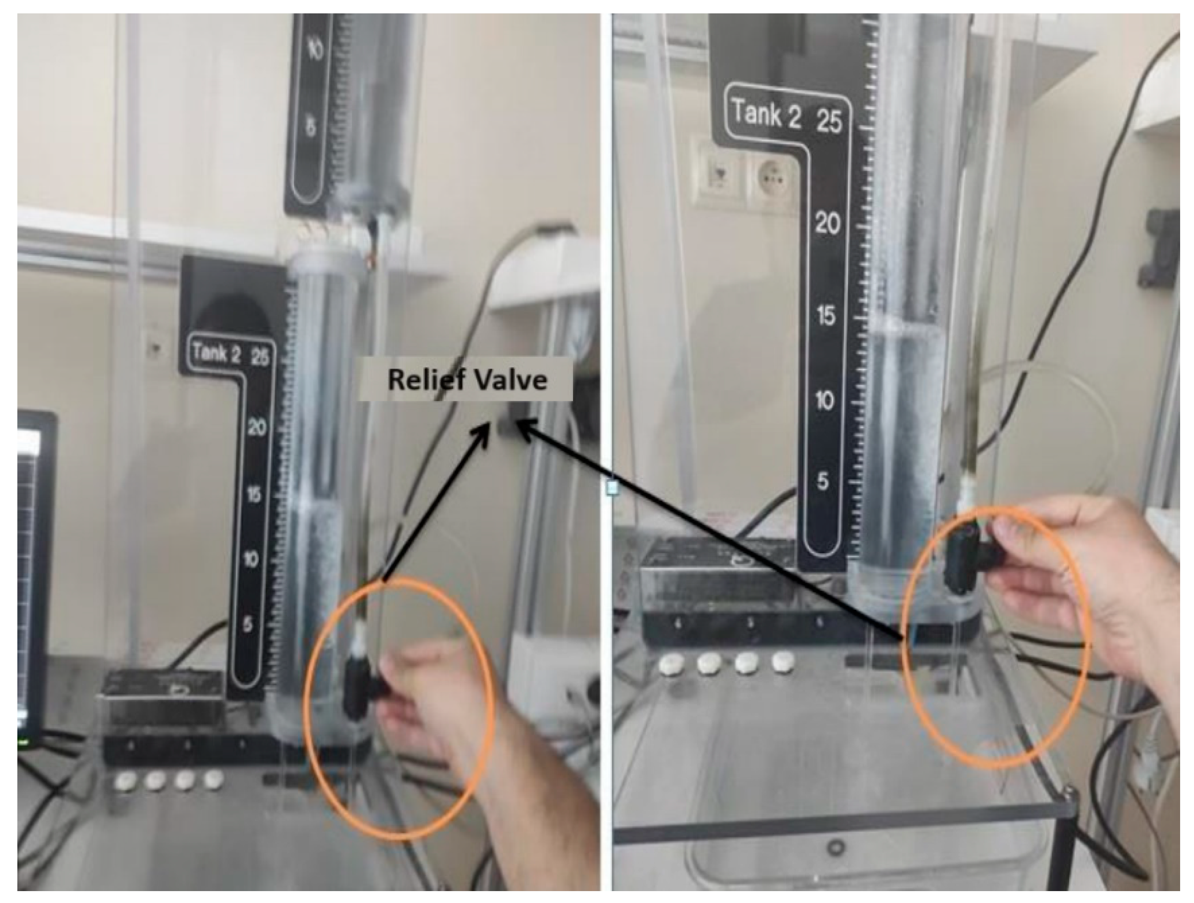
Figure 9.
Tank-1 liquid level control giving instant disturbance effect.
Figure 9.
Tank-1 liquid level control giving instant disturbance effect.
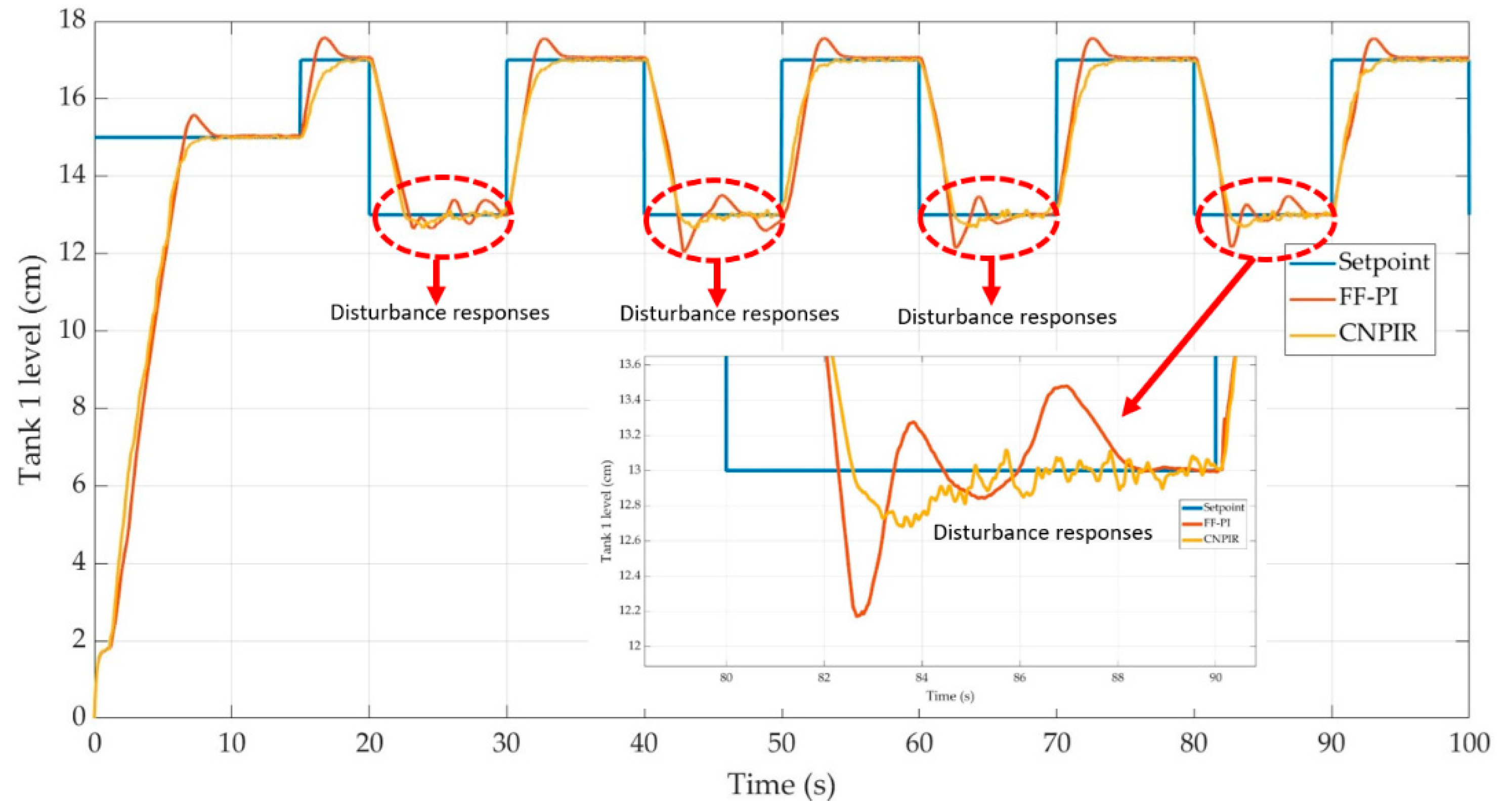
Figure 10.
Square wave responses during disturbance for Tank 1 configuration.
Figure 10.
Square wave responses during disturbance for Tank 1 configuration.
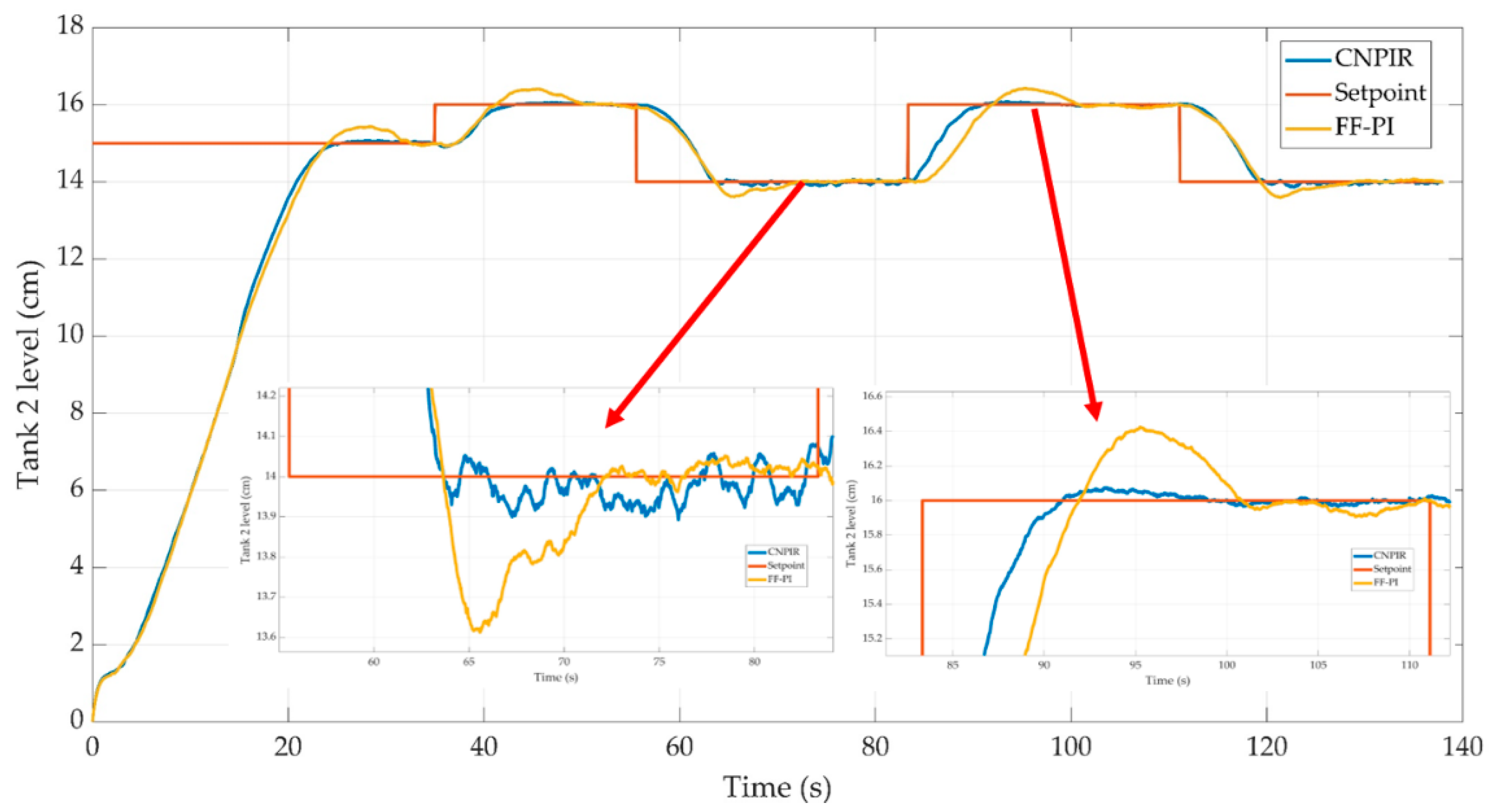
Figure 11.
Control performances of the CNPIR and FF-PI controllers for Tank 2.
Figure 11.
Control performances of the CNPIR and FF-PI controllers for Tank 2.
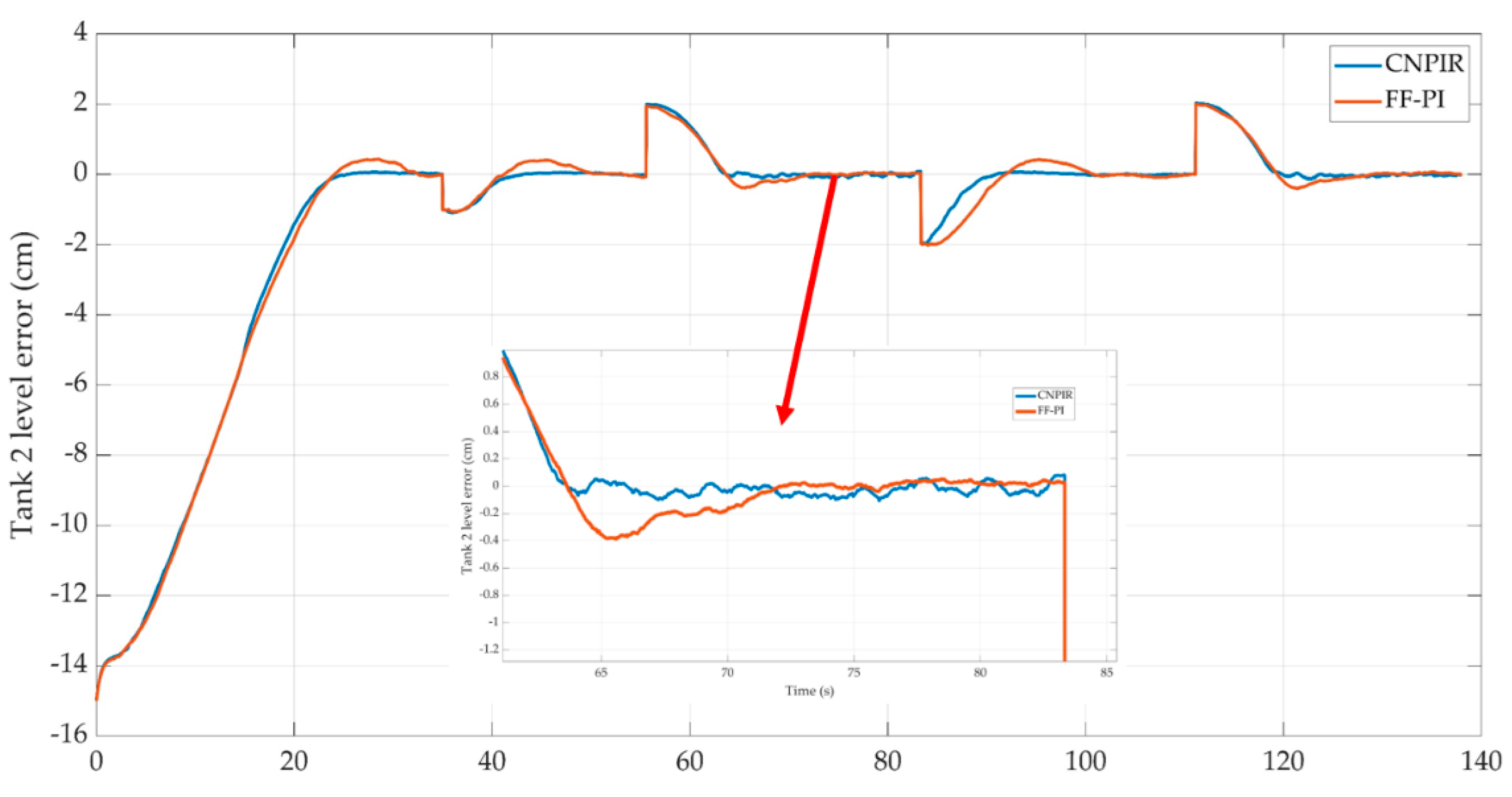
Figure 12.
Tracking error for Tank 2 configuration.
Figure 12.
Tracking error for Tank 2 configuration.
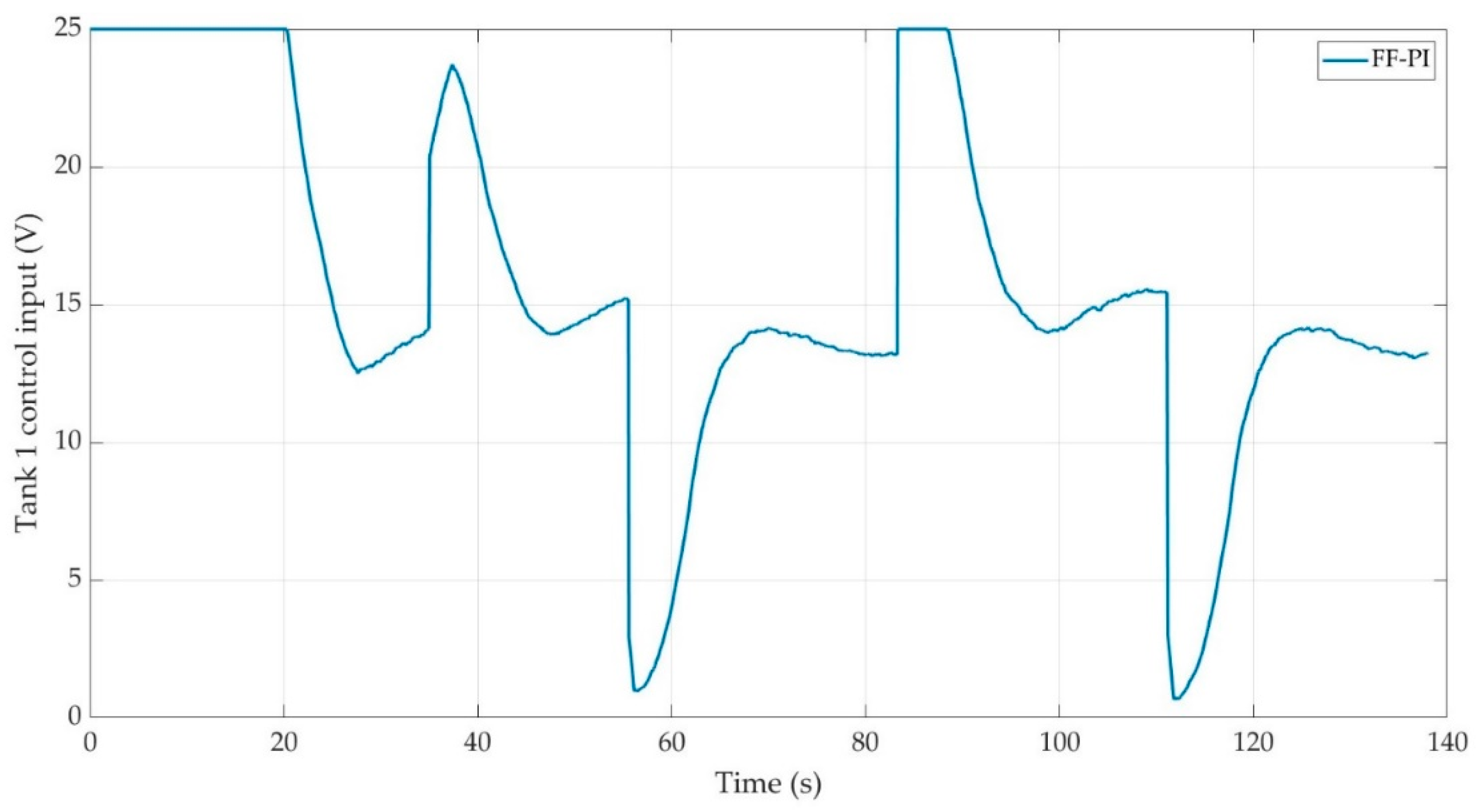
Figure 13.
a. Control input for Tank 2 configuration (FF-PI).
Figure 13.
a. Control input for Tank 2 configuration (FF-PI).
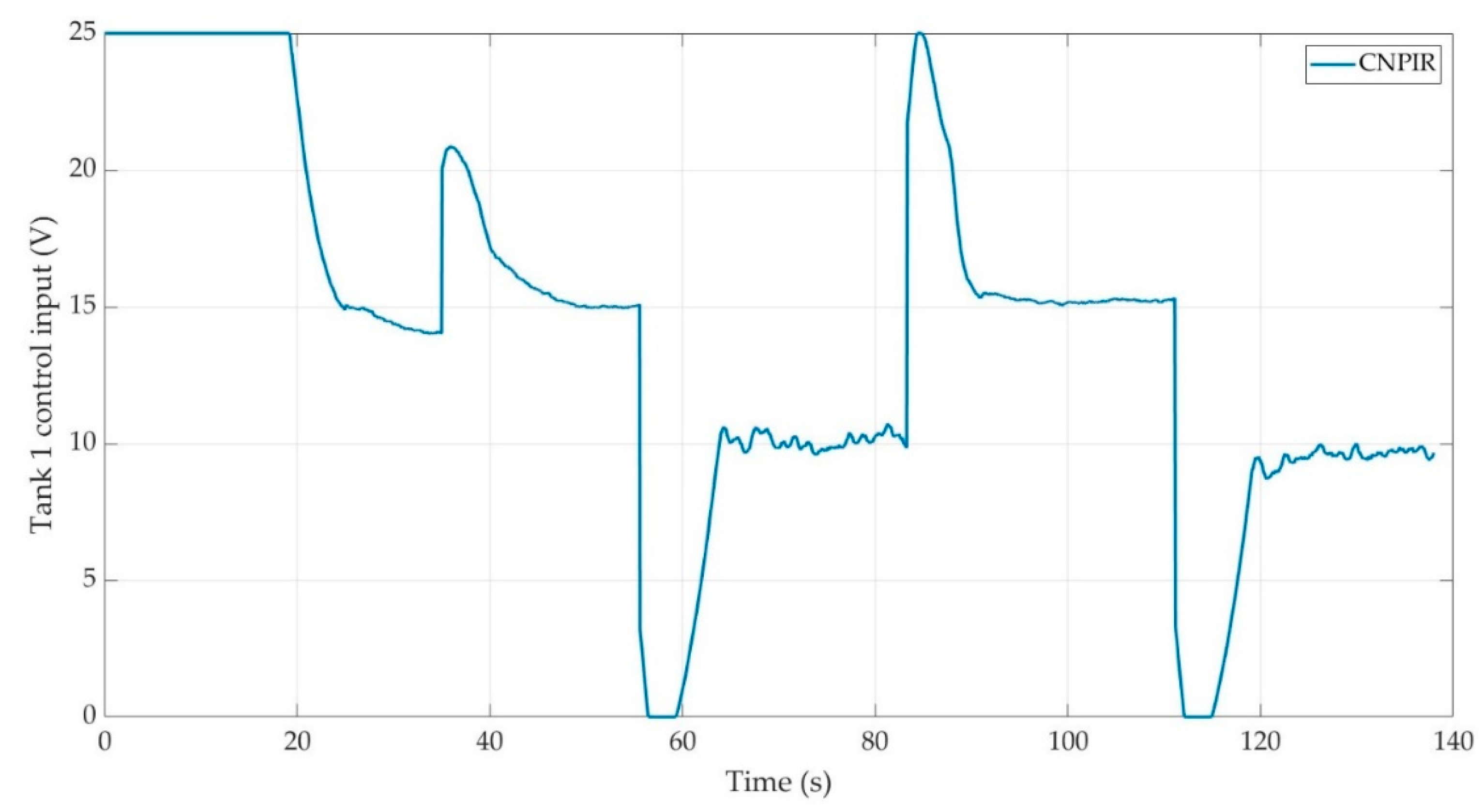
Figure 13.
b. Control input for Tank 2 configuration (CNPIR).
Figure 13.
b. Control input for Tank 2 configuration (CNPIR).
Table 1.
Liquid level system parameters.
Table 1.
Liquid level system parameters.
| Description |
Symbol |
Value & Unit |
| Constant of Pump Flow |
|
|
| Gravitational constant |
|
|
| Tank 1&2 Outlet Areas |
|
|
| Tank 1&2 Inside Cross-Section Areas |
|
|
Table 2.
Liquid level system parameters.
Table 2.
Liquid level system parameters.
| FF-PI Parameters |
|---|
|
= 7.2152 |
= 9.1061 |
= 2.391 |
| CNPIR Control Parameters |
| Square Wave |
G= 0.442 |
h=0.002 |
= 0.88 |
= 26 |
= 0.01 |
Table 3.
ISE values without disturbance according to controllers for Tank 1.
Table 3.
ISE values without disturbance according to controllers for Tank 1.
| |
FF-PI |
CNPIR |
| ISE |
630 |
552.9 |
Table 4.
ISE values according to CNPIR h parameter change.
Table 4.
ISE values according to CNPIR h parameter change.
| Controller |
h value |
ISE |
| CNPIR |
2 ms |
552.9 |
| CNPIR |
10 ms |
552.5 |
| CNPIR |
90 ms |
552.7 |
| CNPIR |
100 ms |
557.2 |
| CNPIR |
200 ms |
577.4 |
| CNPIR |
300 ms |
596.7 |
| CNPIR |
1 s |
694.1 |
Table 5.
ISE values with disturbance according to controllers for Tank 1.
Table 5.
ISE values with disturbance according to controllers for Tank 1.
| |
FF-PI |
CNPIR |
| ISE |
638.3 |
579.3 |
Table 6.
Liquid level Tank 2 system parameters.
Table 6.
Liquid level Tank 2 system parameters.
| |
FF-PI parameters |
|
|
= 5.09 |
= 1.74 |
= 1 |
| |
CNPIR control parameters |
|
|
Square Wave G= 1.02 |
h=0.1 = 10 |
= 0.3 = 0.6 |
Table 7.
ISE values for Tank 2.
Table 7.
ISE values for Tank 2.
| |
FF-PI |
CNPIR |
| ISE |
1743 |
1604 |
