Submitted:
05 August 2024
Posted:
07 August 2024
You are already at the latest version
Abstract
Keywords:
1. Introduction
2. Analysis Model of Levitating Force
2.1. Analysis Model of Buoyancy Force
2.2. The Correlation between the Levitating Force and the Levitating Position of the MC
2.3. Verification of the Levitating Force Model and Magnetic Flux Leakage Parameters
2.4 Dynamic Model of Levitating System
A Levitating Control System Based on Active Disturbance Rejection
3.1. Design of Active Disturbance Rejection Controller for Levitating Control System
3.2. Simulation Analysis of the Levitating Control System
4. Experimental Testing of the Levitating Control System
5. Conclusions
Author Contributions
Funding
Institutional Review Board Statement
Informed Consent Statement
Data Availability Statement
Acknowledgments
Conflicts of Interest
References
- Sun, J.-Y.; Li, P.; Zheng, Y.; Tian, C.-L.; Zhou, Z.-Z. A novel magnetic circuit and structure for magnetic levitation ruler. Measurement and Control 2023, 56, 1545–1561. [Google Scholar] [CrossRef]
- Zhou, Z.-Z.; Wang, H.-X.; Liu, B.-S. Levitation position control of a precise 6-DOF Planar magnetic Levitation stage. Machine Tool and Hydraulics 2018, 46, 125–131. [Google Scholar]
- Liu, L.-L.; Zhou, J.-H. Parameter Self-adjusting Control Method of Fuzzy PID for Magnetic Levitation Ball System. Control Engineering of China 2021, 28, 354–359. [Google Scholar] [CrossRef]
- Hernández-Guzmán, V.M.; Silva-Ortigoza, R.; Marciano-Melchor, M. Position Control of a Maglev System Fed by a DC/DC Buck Power Electronic Converter. Complexity 2020, 2020, 1–16. [Google Scholar] [CrossRef]
- Debdoot, S. Real-Time implementation and performance analysis of robust 2-DOF PID controller for Maglev system using pole search technique. Journal of Industrial Information Integration 2019, 15, 183–190. [Google Scholar] [CrossRef]
- Aysen, D.; Serdar, E.; Baran, H.; Davut, I. Opposition-based artificial electric field algorithm and its application to FOPID controller design for unstable magnetic ball levitating system. Engineering Science and Technology, an International Journal 2021, 24, 469–479. [Google Scholar] [CrossRef]
- Chauhan, D.; Yadav, A. Stability and agent dynamics of artificial electric field algorithm. Journal of Supercomputing 2024, 80, 835–864. [Google Scholar] [CrossRef]
- Deepa, T.; Subbulekshmi, D.; Lakshmi, P.; Maheedhar, M.; Kishore, E.; Vinodharanai, M.; Chockalingam, T. Comparative Study of Different Controllers for Levitating Ferromagnetic Material. Advances in Materials Science and Engineering 2022, 2022, 1–8. [Google Scholar] [CrossRef]
- Pandey, S.; Dourla, V.; Dwivedi, P.; Junghare, A. Introduction and realization of four fractional-order sliding mode controllers for nonlinear open-loop unstable system: a magnetic levitation study case. Nonlinear Dynamics 2019, 98, 601–621. [Google Scholar] [CrossRef]
- Yaseen, H.M.S.; Siffat, S.A.; Ahmad, I.; Malik, A.S. Nonlinear adaptive control of magnetic levitation system using terminal sliding mode and integral backstepping sliding mode controllers. ISA transactions 2022, 126, 121–133. [Google Scholar] [CrossRef]
- Acharya, D.S.; Swain, S.K.; Mishra, S.K. Real-Time Implementation of a Stable 2 DOF PID Controller for Unstable Second-Order Magnetic Levitation System with Time Delay. Arabian journal for science and engineering 2020, 45, 6311–6329. [Google Scholar] [CrossRef]
- Gopi, R.S.; Srinivasan, S.; Panneerselvam, K.; Teekaraman, Y.; Kuppusamy, R.; Urooj, S. Enhanced Model Reference Adaptive Control Scheme for Tracking Control of Magnetic Levitation System. Energies 2021, 14, 1455. [Google Scholar] [CrossRef]
- Kim, S.K.; Ahn, C.K. Sensorless non-linear position-stabilising control for magnetic levitation systems. IET Control Theory and Applications 2020, 14, 2682–2687. [Google Scholar] [CrossRef]
- Zhu, H.; Teo, T.J.; Pang, C.K. Magnetically Levitated Parallel Actuated Dual-Stage (Maglev-PAD) System for Six-Axis Precision Positioning. IEEE/ASME Transactions on Mechatronics 2019, 24, 1829–1838. [Google Scholar] [CrossRef]
- Trbusic, M.; Jesenik, M.; Trlep, M.; Hamler, A. Energy Based Calculation of the Second-Order Levitation in Magnetic Fluid. Mathematics 2021, 9, 2507. [Google Scholar] [CrossRef]
- Li, Y.-Q.; Feng, G.-S.; Wang, X.-F.; Wu, J.-Z.; Ma, J.; Xiao, L.-T.; Jia, S.-T. Reduction of characteristic RL time for fast, efficient magnetic levitation. AIP Advances 2017, 7, 095016. [Google Scholar] [CrossRef]
- Wu, C.; Li, S.-S. Modeling, Design and Suspension Force Analysis of a Novel AC Six-Pole Heteropolar Hybrid Magnetic Bearing. Applied Sciences 2023, 13, 1643. [Google Scholar] [CrossRef]
- Chen, W.; Tong, J.-Q.; Yang, H.-H.; Liu, F.-L.; Qin, Z.; Ren, Z.-Y. Modeling and Vibration Analysis of a 3-UPU Parallel Vibration Isolation Platform with Linear Motors Based on MS-DT-TMM. Shock and Vibation 2021, 2021, 1–17. [Google Scholar] [CrossRef]
- Yu, T.-T.; Zhang, Z.-Z.; Li, Y.; Zhao, W.-L.; Zhang, J.-C. Improved active disturbance rejection controller for rotor system of magnetic levitation turbomachinery. Electronic Research Archive 2023, 31, 1570–1586. [Google Scholar] [CrossRef]
- Tan, L.-L.; Chen, Z.-X.; Gao, Q.-H.; Liu, J.-F. Performance recovery of uncertain nonaffine systems by active disturbance rejection control. Measurement and Control 2024, 57, 3–15. [Google Scholar] [CrossRef]
- Sun, X.-D.; Jin, Z.-J.; Chen, L.; Yang, Z.-B. Disturbance rejection based on iterative learning control with extended state observer for a four-degree-of-freedom hybrid magnetic bearing system. Mech. Syst. Signal Process 2021, 153, 107465. [Google Scholar] [CrossRef]
- Wei, Z.-X.; Huang, Z.-W.; Zhu, J.-M. Position Control of Magnetic Levitation Ball Based on an Improved Adagrad Algorithm and Deep Neural Network Feedforward Compensation Control. Mathematical Problems in Engineering 2020, (2020), 1–13. [Google Scholar] [CrossRef]
- Gopi, R.S.; Srinivasan, S.; Panneerselvam, K.; Teekaraman, Y.; Kuppusamy, R.; Urooj, S. Enhanced Model Reference Adaptive Control Scheme for Tracking Control of Magnetic Levitation System. Energies 2021, 14, 1455. [Google Scholar] [CrossRef]
- He, H.-C.; Si, T.-T.; Sun, L.; Liu, B.-T.; Li, Z.-B. Linear Active Disturbance Rejection Control for Three-Phase Voltage-Source PWM Rectifier. IEEE Access 2020, 45050–45060. [Google Scholar] [CrossRef]

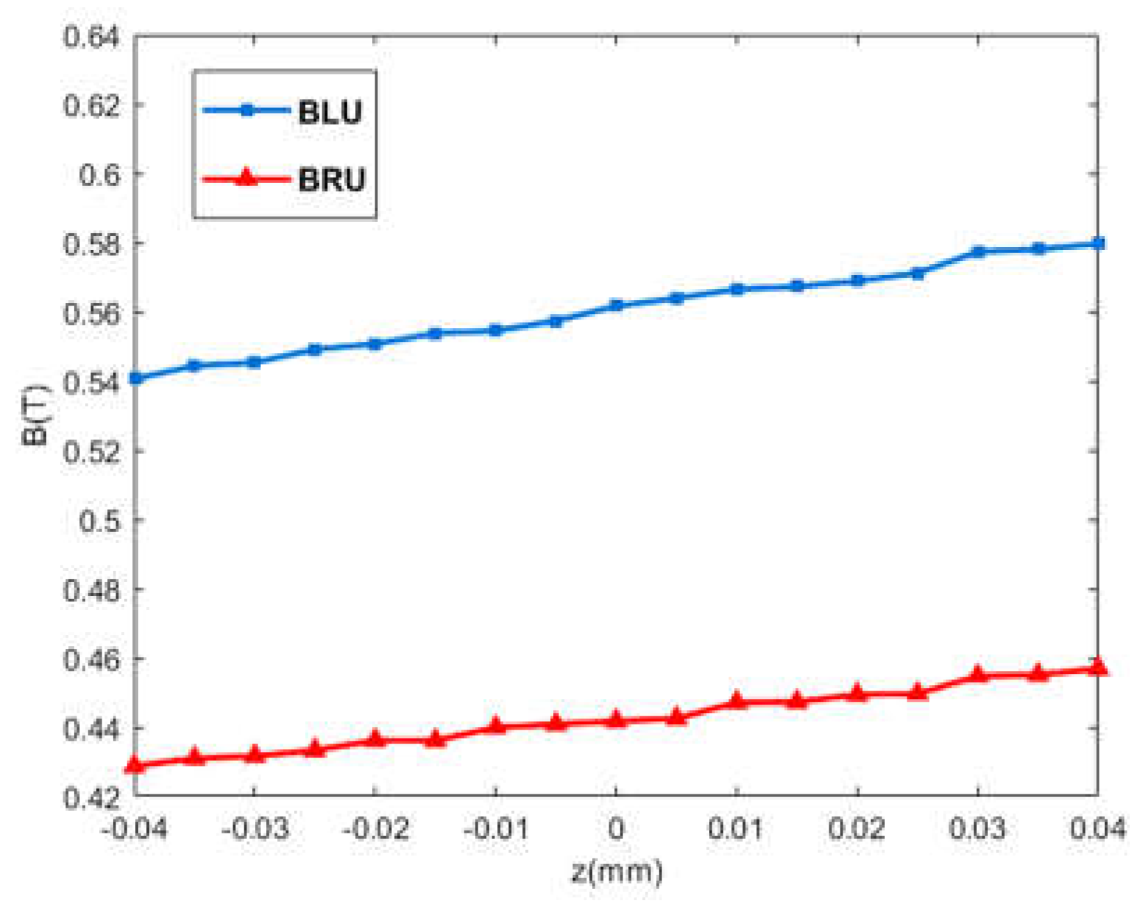
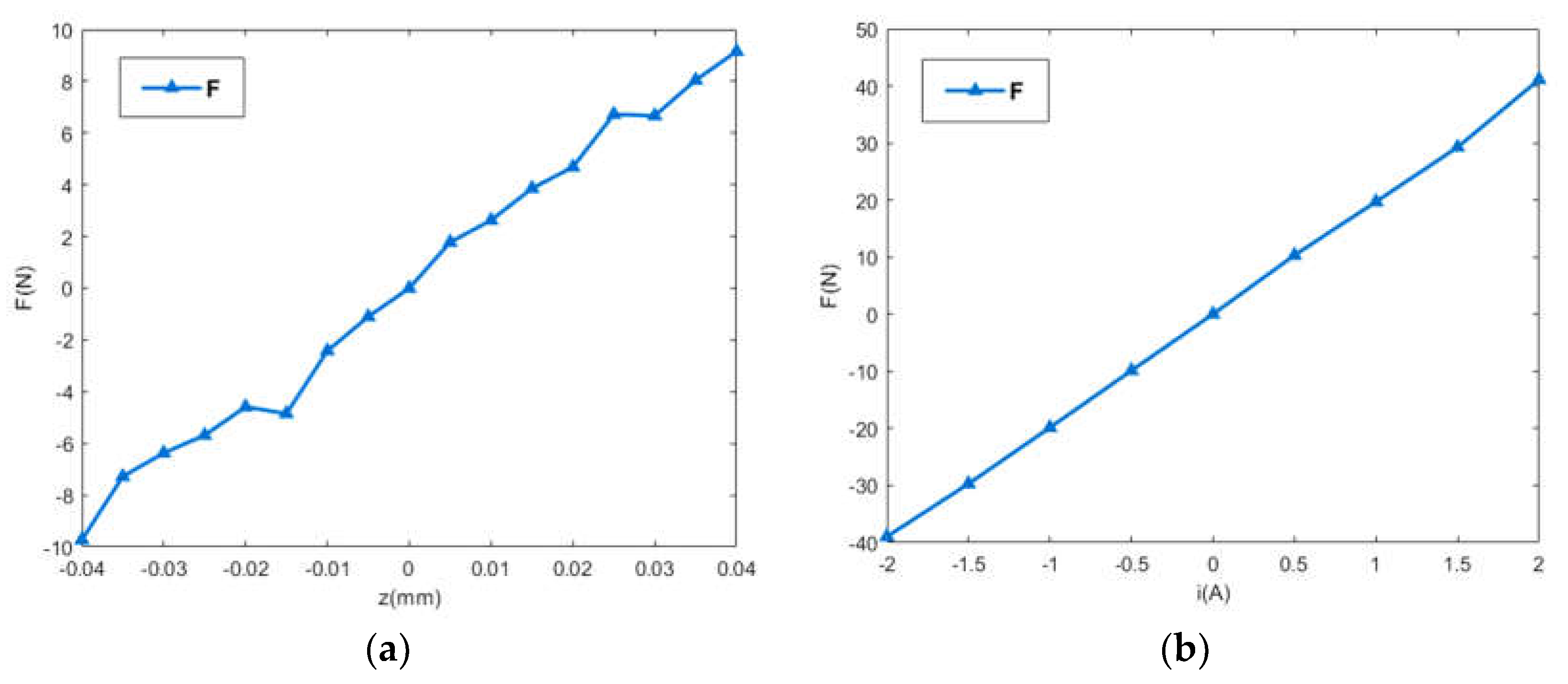
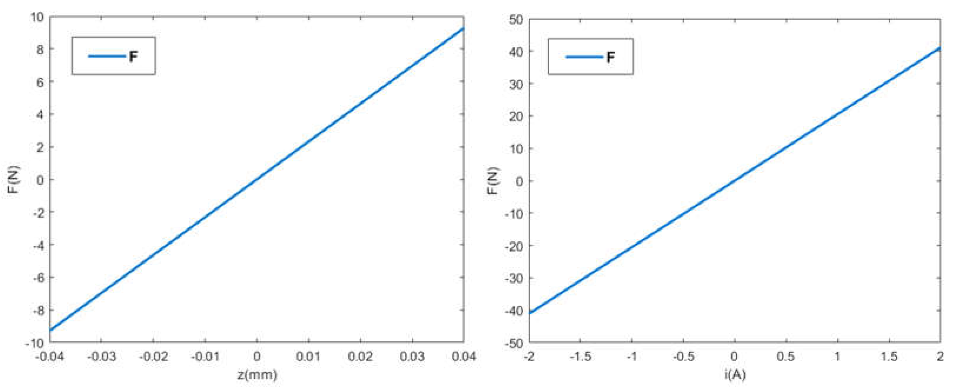

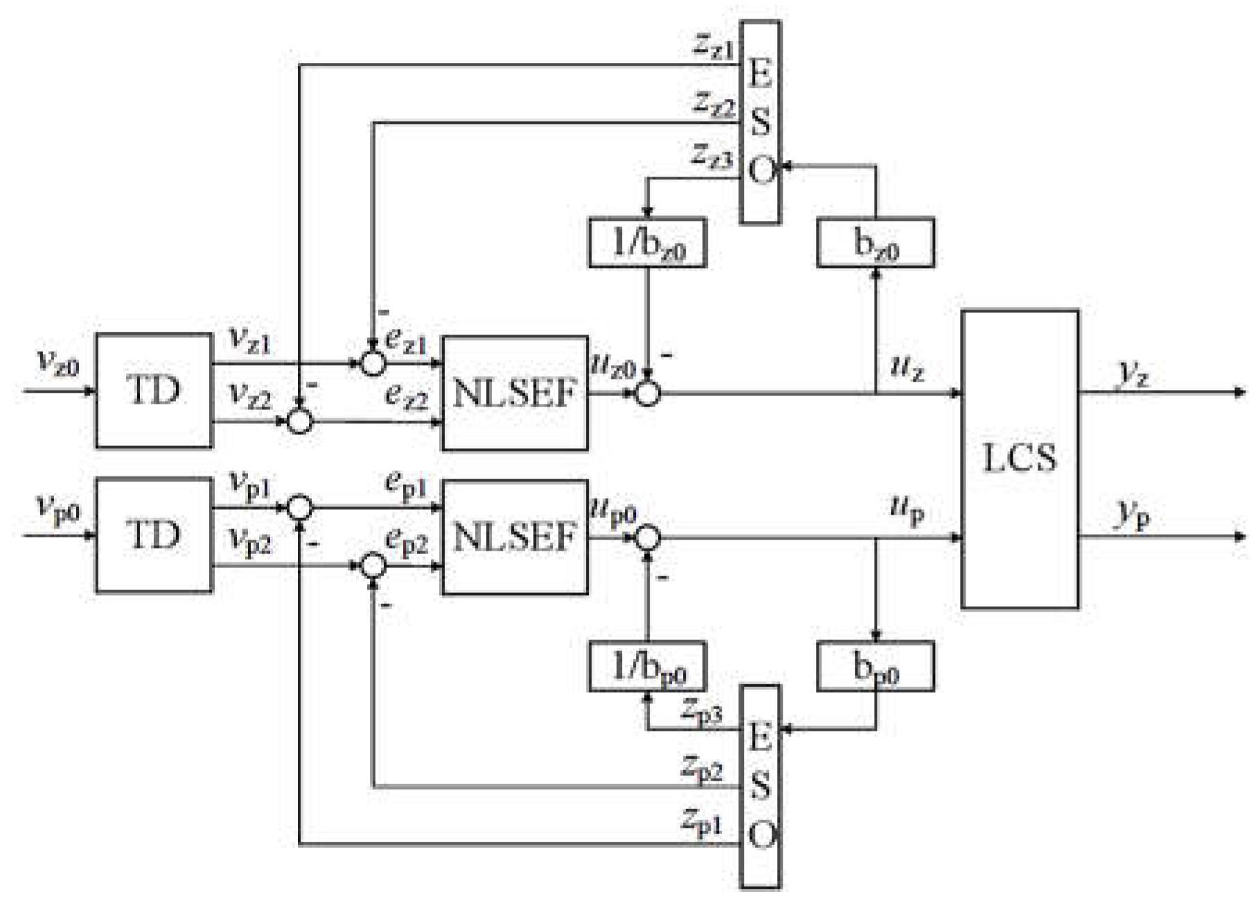
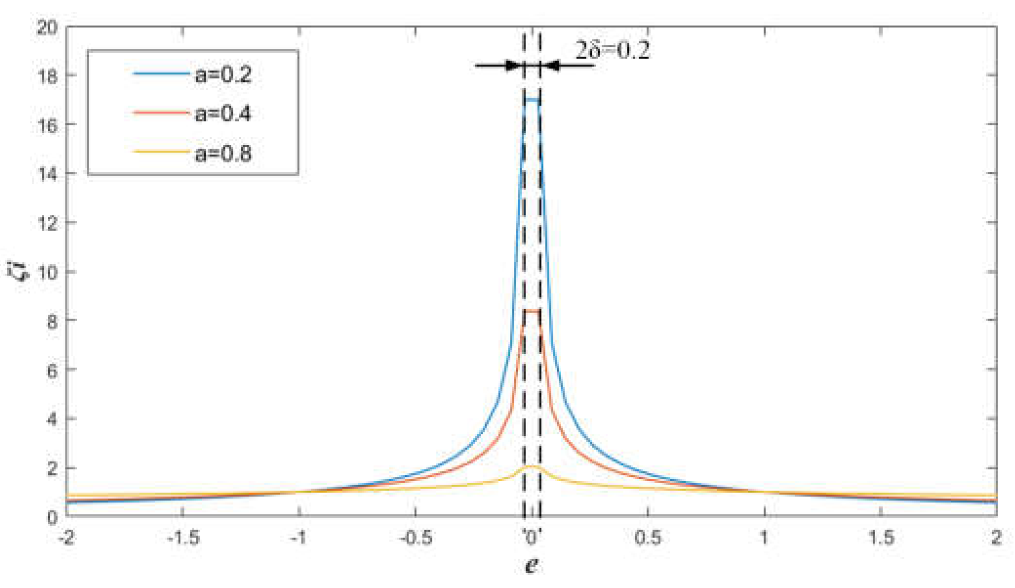
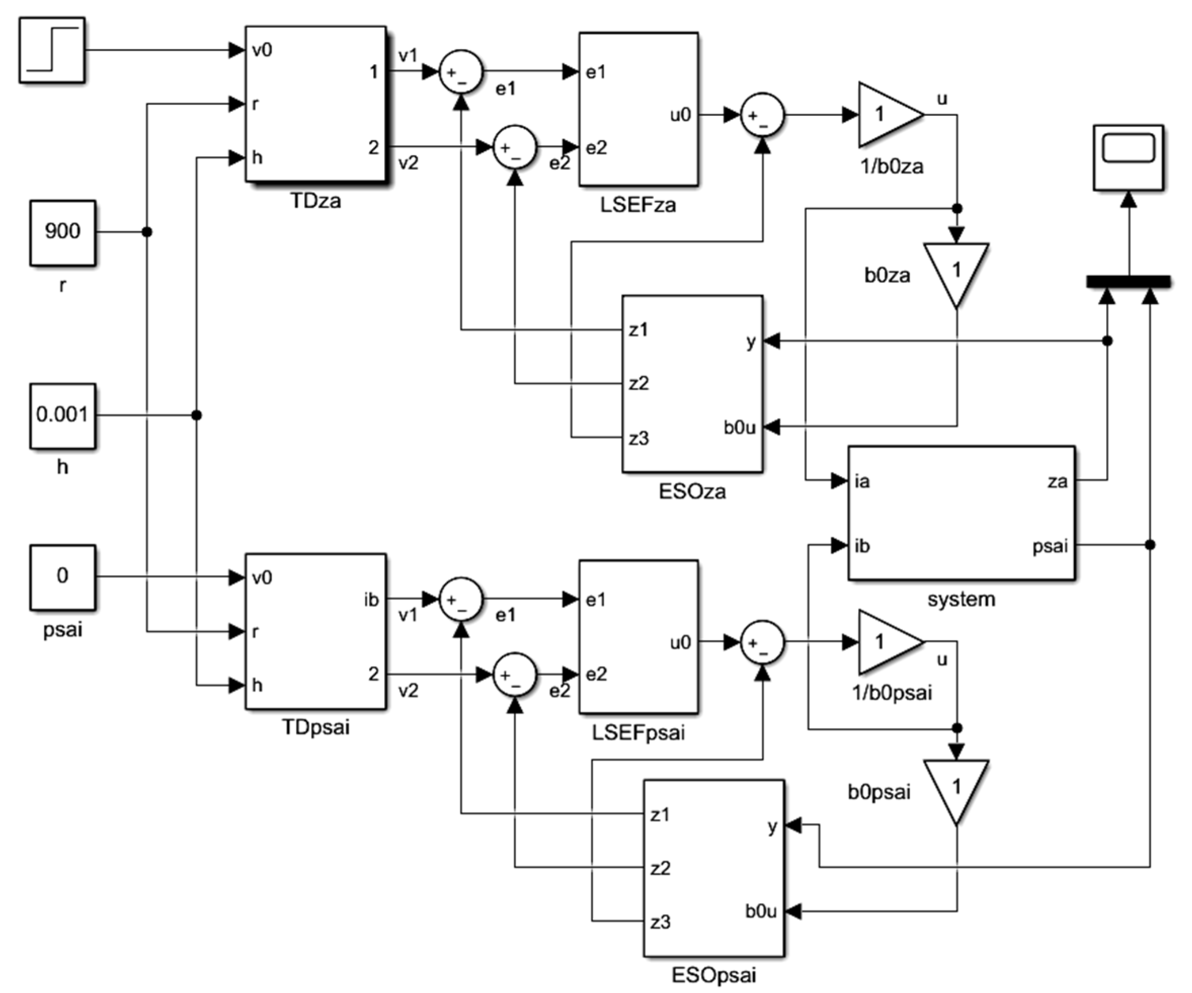
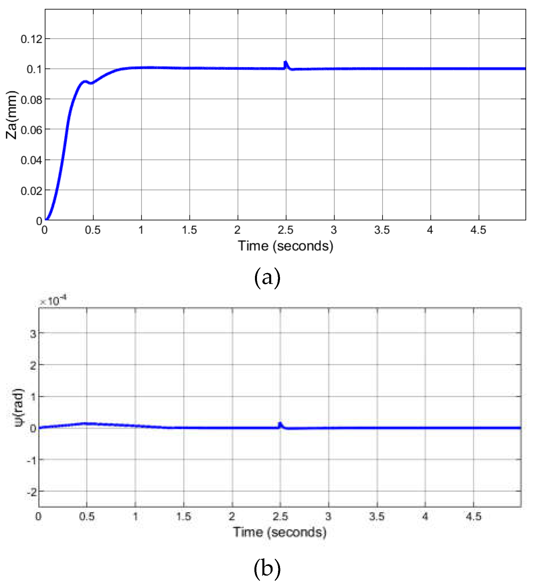
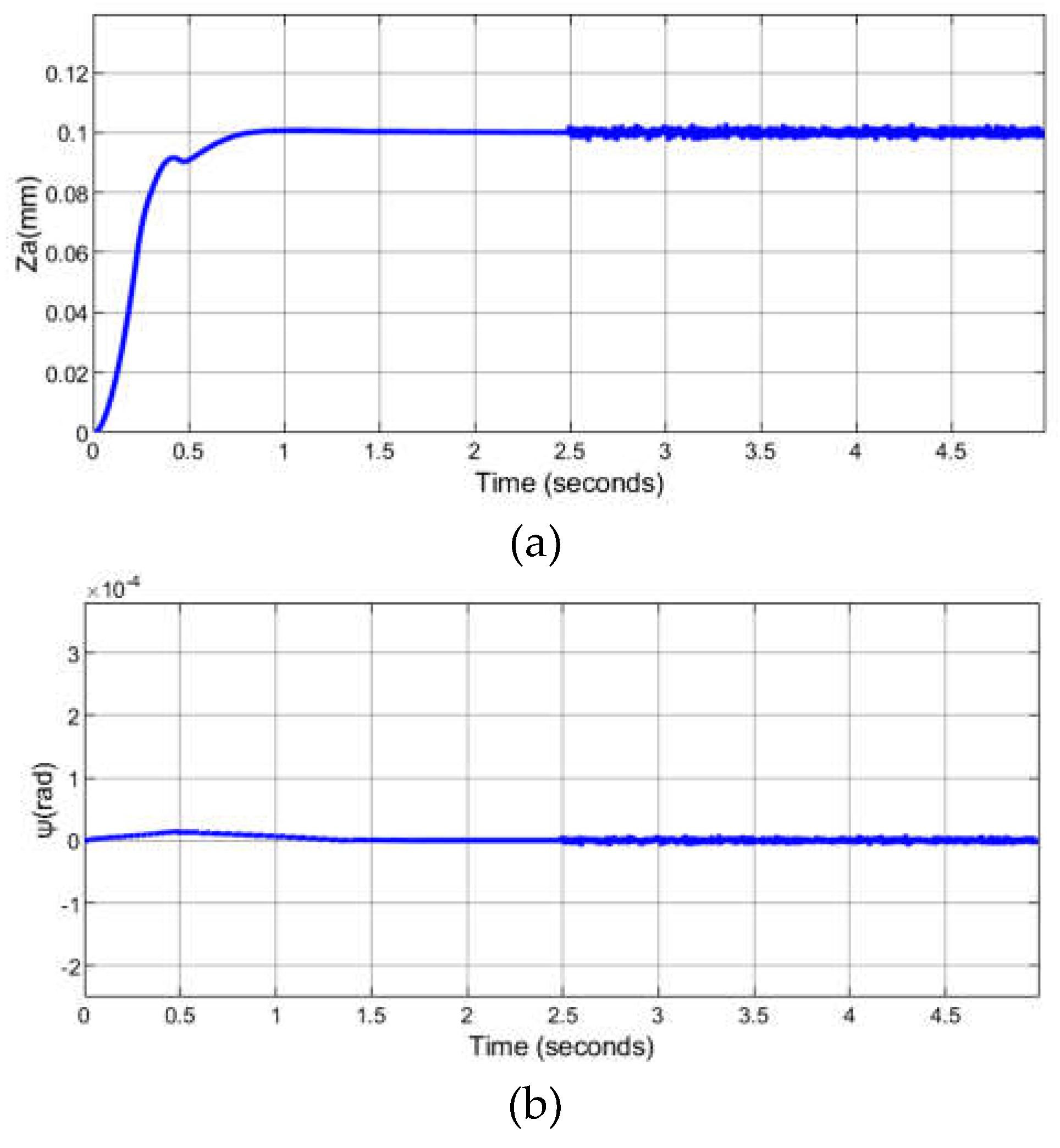
| parameter | value | parameter | value | parameter | value |
|---|---|---|---|---|---|
| r | 900 | βe2 | 1398 | βf2 | 0.01 |
| h | 0.001 | βe3 | 1015 | a2 | 0.25 |
| βe1 | 200 | βf1 | 30 | a3 | 0.5 |
Disclaimer/Publisher’s Note: The statements, opinions and data contained in all publications are solely those of the individual author(s) and contributor(s) and not of MDPI and/or the editor(s). MDPI and/or the editor(s) disclaim responsibility for any injury to people or property resulting from any ideas, methods, instructions or products referred to in the content. |
© 2024 by the authors. Licensee MDPI, Basel, Switzerland. This article is an open access article distributed under the terms and conditions of the Creative Commons Attribution (CC BY) license (https://creativecommons.org/licenses/by/4.0/).


