1. Introduction
The construction of shafts to directly access underground in urban areas is increasing considerably around the world [
1,
2,
3,
4,
5,
6]. Although some innovative shapes have been employed [
7,
8,
9], the circular shape is clearly the most commonly adopted due to its structural superiority, which minimizes the lining thickness and the ground deformations due to the development of the arching effect in the perpendicular plane to the excavation [
10,
11]. As a result of that arching effect the use of classical earth pressure theories, such as those proposed by Coulomb [
12] or Rankine [
13] derived for plane strain conditions are not suitable and lead to over-conservative predictions of the earth pressure [
11,
14]. Consequently, many authors have developed methods to calculate the axisymmetric earth pressure acting on a shaft based on different frameworks [
15,
16,
17,
18,
19,
20,
21,
22,
23,
24].
Unfortunately, for some of those methods there are no analytical solutions available making them cumbersome to use in practice. Moreover, all methods present limitations, which can have a relevant impact on the predicted horizontal earth pressures (referred to as earth pressures from this point forward). One assumption that is common to all methods, apart from that proposed by Guojun, et al. [
22], is that the circumferential stress ratio (
) is constant with depth. Often a value of 1 is assumed (Haar and von Kármán hypothesis) while in other cases a different value can be selected [
23]. According to Cheng, et al. [
25]
tends to increase from
to 1 during the shaft construction, reflecting the arching effect, while the radial stress ratio (
) tends to decrease from
to
as verified in plane strain conditions. However, Guojun, et al. [
22] opposes the hypothesis of defining a circumferential stress ratio claiming that this assumption is merely speculation and does not have a deep theoretical basis. That claim is supported to some extent by the results of the numerical analyses performed by Janeiro, et al. [
11] where it is shown that
begins equal to
but its value varies with depth as the shaft is excavated. However, the results also show that for large shaft movements
tends to become equal to 1 along the entire shaft depth, as suggested by Cheng, et al. [
25].
Another limitation common to all methods is that an active limit state is assumed for the evaluation of earth pressures. However, for this condition to be admissible a significant lateral movement of the shaft is required. Although there are some discrepancies among studies [
26] a value of 0.3% of its height (
) is generally accepted as enough to mobilize the active limit state [
21]. In the case of circular shafts, that lateral displacement might not be possible to achieve since the movements are often restricted by the high stiffness of the lining ring and are also very dependent on the construction method employed in the excavation. As shown by Faustin, et al. [
1] the construction method is directly related with the magnitude of the ground movements. In the cases where the support is installed prior to the excavation (
SBE - Support Before Excavation) the movement is almost inexistent, and the earth pressures remain almost identical to those in greenfield conditions [
27,
28]. In contrast, when the excavation is performed in advance and only after the lining is installed (
EBS - Excavation Before Support) there is a significant soil decompression that leads to large movements towards the opening, with the consequent reduction of the earth pressure. Moreover, even in the cases where the shaft is excavated following the
EBS methodology, the field [
29,
30] and numerical [
31,
32] results suggest that an active limit state is not reached in typical construction conditions.
This latter limitation is particularly relevant since the active earth pressures are non-conservative and should not be employed in practise unless shaft lateral displacements higher than
are expected to occur. One attempt to account with the lateral shaft displacements directly in the evaluation of the earth pressures was made by Liu [
21]. The author proposed Equations 1 and 2 for the determination of the mobilised friction angle (
) and of the circumferential stress ratio (
) as a function of the shaft normalized displacement (
). According with Liu [
21] at initial conditions
corresponds to the initial angle of internal friction,
(Equation 3), and
, and as the shaft lateral displacement (
) increases both parameters vary, reaching at the active limit state values of
(soil friction angle) and
.
with
given by Jaky’s [
33] equation (
).
However, as Liu [
21] acknowledges the relationships defined influence the accuracy of the predictions and further refinement and validation of those are necessary. It should also be pointed that while different
and
are employed for each shaft lateral displacement the earth pressures prediction is still performed based on an analytical solution deduced based on an active limit state.
Considering these limitations and the demand for a more global solution, this paper presents a new methodology capable of incorporating shaft lateral displacements in the prediction of earth pressures acting on circular shafts. The method is developed having as reference the results of relevant physical tests, both small scale and centrifuge, where the shaft excavation was simulated. Based on the measured results it was possible to define an expression that relates the reduction of the earth pressure with the shaft lateral displacements, varying from the initial stress state ( condition) until an active limit state is reached. The obtained results show good agreement with the measured data and represent an improvement on the previous methods, making the methodology suitable for being used at early stages of design.
2. Comparison of the Analytical Methods
As mentioned previously, the classical earth pressure theories derived for plane strain conditions are not applicable in circular shafts, where axisymmetric conditions prevail. As a result, several authors developed and proposed analytical methods for evaluating the active earth pressure acting on circular shafts [
15,
16,
17,
18,
19,
20,
21,
22,
23,
24]. These methods can be divided into three principal groups according to their frameworks. (1) The limit equilibrium theories proposed by Terzaghi [
15] and Prater [
17], where a suitable failure surface is adopted and a minimum pressure is determined in order to ensure the static equilibrium of the soil wedge. (2) A different approach was followed by Berezantzev [
16] and further extended by Cheng, et al. [
18], Liu, et al. [
19], Liu, et al. [
20], Liu [
21] and Guojun, et al. [
22] where the slip line method was employed to derive the partial differential equations governing the plastic equilibrium of a conical surface. (3) Wong and Kaiser [
24] proposed a methodology based on the convergence-confinement method usually applied for tunnels under isotropic stress conditions. However, this latter approach is usually not considered since it does not take into account the important effect of gravity forces. A detailed description of all these methods and derived equations is out of the scope of this work and can be found in the references provided.
The general expression for evaluating the active earth pressure acting on a circular shaft is similar to that proposed for plane strain conditions by the classical theories (Equation 4), with the difference being the earth pressure coefficients (
,
and
), which were deduced for axisymmetric conditions.
In the expression
represents the unit weight of the soil,
the depth,
the cohesion and
a surcharge applied at ground surface. A list of all input parameters required for each analytical solution is presented in
Table 1. All methods use Mohr-Coulomb as failure criterion (although in some cases just for cohesionless soils), except the method proposed by Guojun, et al. [
22], where Drucker–Prager failure criterion was adopted, so that it could describe the axisymmetric limit problem without the need for defining a constant circumferential stress ratio. It should also be mentioned that Guojun, et al. [
22] also consider in his expression the soil dilation effect through the plastic potential parameter,
. The most employed analytical method was proposed by Berezantzev [
16], where the Haar and von Kármán hypothesis (
) is adopted. Having as reference this method Cheng, et al. [
18] and then Liu, et al. [
20] proposed an extension to allow the definition of a different circumferential stress ratio,
. Liu, et al. [
19] also derived a solution to include as parameters the inclination of the shaft (
), the backfill inclination (
) and the soil-shaft friction angle (
), while keeping a
. As mentioned previously, the latest development made by Liu [
21] was to include in the Liu, et al. [
20] formulation the adoption of a normalized lateral displacement (
) as an input parameter, which, through Equations 1 and 2, adjusts the
and
values.
In order to compare the active earth pressures estimated by the different analytical solutions a parametric study was performed. For this purpose, a soil with a unit weight of 20kN/m
3, a friction angle of 40º, a cohesion of 0kPa and no-dilatant (
) was adopted. A levelled ground surface, without the presence of any surcharge, and a vertical shaft with a depth of 30m and a radius of 3m were also assumed. For the solutions proposed by Prater [
17], Cheng, et al. [
18] and Liu, et al. [
20] the active earth pressures were determined considering
equal to
and 1, in order to assess the influence of this parameter. For the methodology proposed by Liu [
21] shaft lateral displacements of 0 (corresponding to a
condition),
,
,
and
(corresponding to an active limit state) were considered.
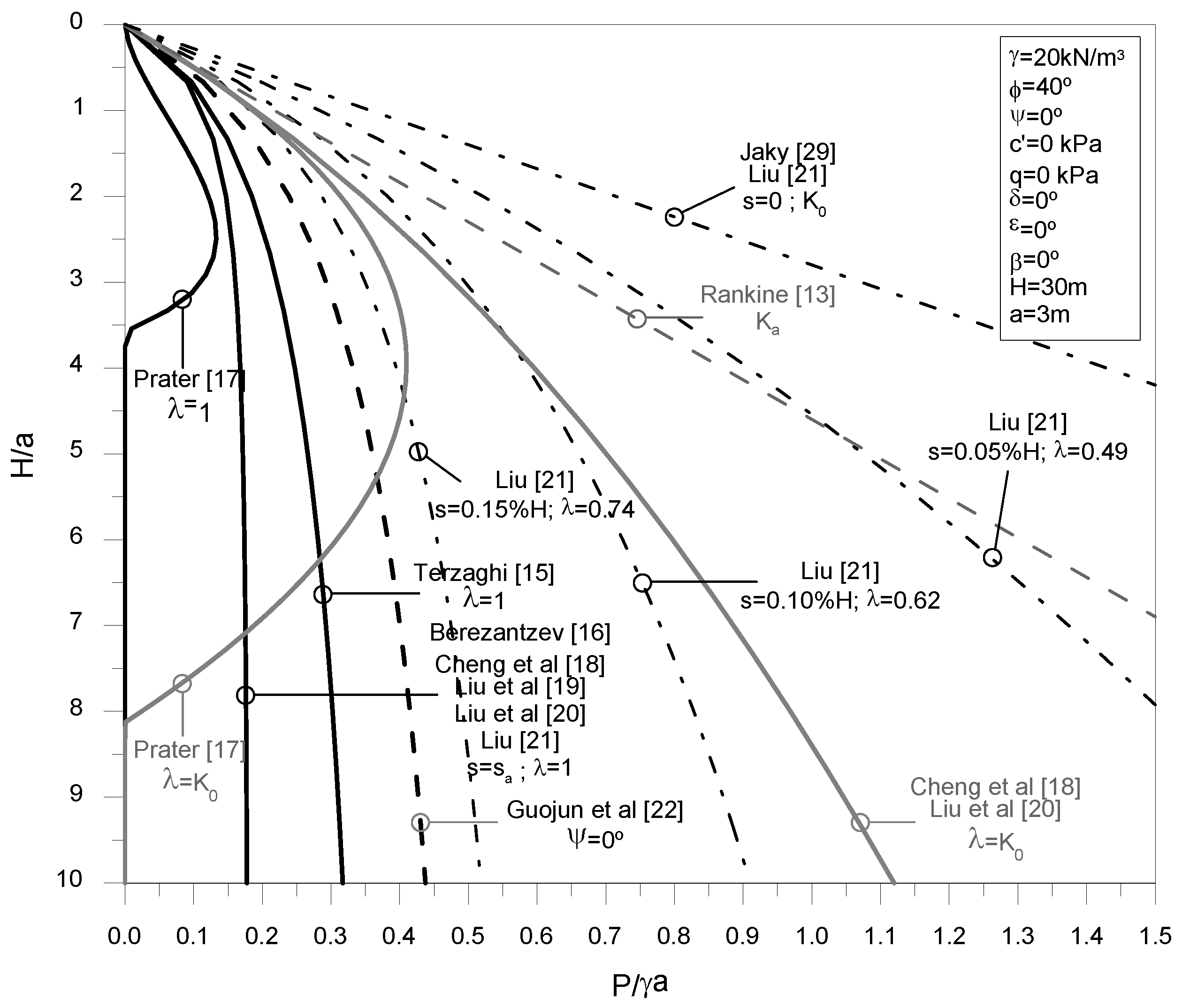
The evolution of the normalised earth pressure (
) with the normalised depth (
) is presented in
Figure 1. Superimposed in the figure are represented the active and at-rest earth pressures determined for the plane strain conditions using the Rankine [
13] and Jaky [
33] proposals. The results confirm that all axisymmetric methods estimate an active earth pressure smaller than that obtained by the plane strain theories, with the difference being particularly relevant as depth increases, since in the axisymmetric case the earth pressure tends to stabilize with depth as a result of the arching effect, while in plane strain conditions a typical linear increase with depth is observed.
As expected, the active earth pressures calculated by Berezantzev [
16], Cheng, et al. [
18], Liu, et al. [
19] and Liu, et al. [
20] methods give the exact same results when
is equal to 1. For the same circumferential stress ratio (
) it is possible to observe that Terzaghi [
15] solution estimates an higher active earth pressure distribution, though with a similar trend with depth. The active earth pressures predicted by Prater [
17] for
are smaller and present a different trend, initially increasing with depth and then decreasing to a value of zero. As discussed by Prater [
17] the decrease observed in the active earth pressure is a consequence of the assumptions made in the derivation of the analytical solution and is considered to be unrealistic. Prater [
17] suggests that the maximum value estimated for the active earth pressure should be adopted from that depth further, resulting in a trend similar to that observed in the other analytical solutions.
From the obtained results it is possible to conclude that the stress ratio has an important impact in the prediction of the active earth pressures. For a value equal to
a significant increase in the active earth pressures was observed for both Prater [
17], Cheng, et al. [
18] and Liu, et al. [
20] methods, with the last two predicting equal active earth pressures, as both methods have the same general formulation. These results highlight the importance of adopting an adequate circumferential stress ratio in the prediction of active earth pressures when using these analytical solutions. In contrast, in the method proposed by Guojun, et al. [
22] no circumferential stress ratio is imposed, with the active earth pressure distribution prediction being between the results obtained for
and
, slightly higher than the Terzaghi [
15] proposal.
Finally, in the analyses considering different shaft lateral displacements it is possible to observe the reduction of the earth pressure with the increase of the lateral displacement. For the initial condition (
with
) Liu’s [
21] method predicts exactly the at-rest earth pressures, while for a lateral displacement equal to
(
) the prediction is equal to that obtained by the different slip line methods which consider
. Based on the obtained results it is possible to verify that Liu’s [
21] method can effectively take into account the shaft lateral displacements in the earth pressure prediction.
3. Shaft Excavation Physical Models
The excavation of circular shafts has also been investigated using physical models, such as small-scale models or more elaborate centrifuge tests. These experiments focused primarily on evaluating the earth pressure distribution with depth, although in some cases the ground deformations and associated failure mechanism were also analyzed. One of the first small-scale models reported was performed by Walz [
34] and involved the sinking of a circular shaft in a box filled with sand, reproducing the jacked caisson technique. By modifying the size of the cutting edge, Walz [
34] created a recess between the soil and the lining and observed that the earth pressure decreased considerably with the increase of the recess, which was justified by the larger movements induced in the soil.
Chun and Shin [
35] and Tobar and Meguid [
36] (additional data of these tests are reported in Tran, et al. [
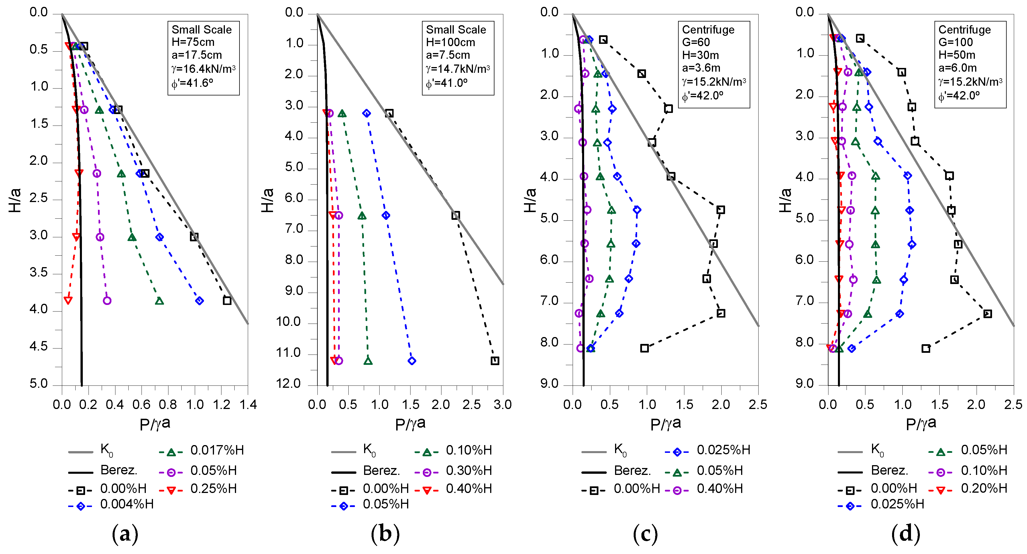
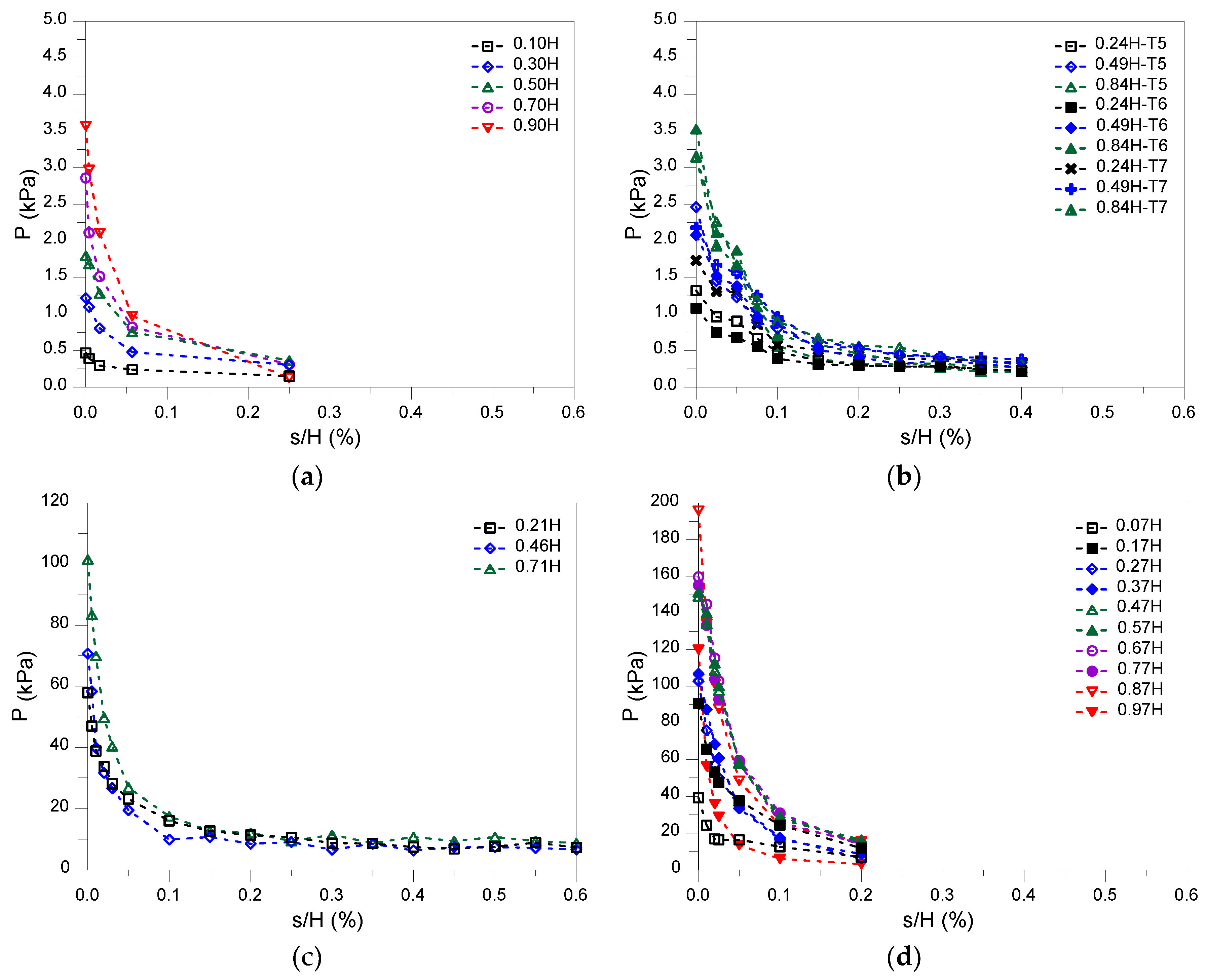
37]) also used small-scale models to assess the evolution of the earth pressures with the increase of the shaft lateral displacement. Both studies used in the tests a dense sand and a similar shaft apparatus, capable of imposing uniform lateral displacements along the shaft perimeter and depth by contracting its lining. To measure the earth pressure several stress transducers were installed along the shaft depth. The main properties of the models are presented in
Table 2 and the principal results are shown in
Figure 2 and
Figure 3. The results of both studies clearly show the impact on the earth pressure caused by the increase of the shaft lateral displacement. For the initial condition (
) the earth pressures are well estimated in both cases by Jaky’s [
33]
proposal. In Chun and Shin [
35] model a shaft lateral displacement of just
caused a reduction in the earth pressure of about 35%.
Figure 3(a) shows that the reduction of earth pressures is highly nonlinear decreasing sharply until a shaft lateral displacement of
and then more gently until the maximum lateral displacement imposed of
. For the maximum lateral displacement imposed it is possible to observe in
Figure 2(a) that the earth pressures measured are very similar to those proposed by Berezantzev [
16] solution where an active limit state is considered, implying that this condition has probably been reached in the test. In Tobar and Meguid [
36] tests a similar behavior is observed, although for a maximum shaft lateral displacement of
the earth pressures measured the earth pressures do not appear to have completely stabilized and are still slightly above from those estimated using Berezantzev [
16] solution, which can be considered a strange result as for that shaft lateral displacement an active limit state should already have been reached. Nevertheless, a similar earth pressure reduction is observed in all tests (T5; T6; T7) as can be seen in
Figure 3(b).
The first centrifuge tests to evaluate the earth pressure induced by shaft excavation were performed by Lade, et al. [
40]. The study confirmed that the earth pressure reduces with the increase of the shaft lateral displacement. However, Lade, et al. [
40] results were influenced by the mechanism used in the centrifuge to simulate the excavation and, consequently, are not considered to be entirely reliable [
26]. In the 90′s several centrifuge tests to evaluate the behavior of shaft excavation were carried out at different Japanese facilities. In all cases the tests were performed in sand and a mechanical system similar to that employed by Chun and Shin [
35] and Tobar and Meguid [
36] was used to apply a contraction in the shaft lining, reducing its radius. Fujii, et al. [
41] observed that the increase of the roughness between soil and lining decreased slightly the earth pressure acting on the shaft. The effects of the lining stiffness and of the radius of the shaft were investigated by Ueno, et al. [
42]. This study observed that the earth pressure increased when stiffer linings were adopted. In contrast, the earth pressure remained almost unchanged for the different shaft radius tested, although it should be mentioned that a very stiff lining was employed in that set of tests, which might have influenced the results. The results of both studies are in agreement with the typical behavior observed in shafts and retaining walls. The soil-wall roughness decreases the horizontal component of the earth pressure and contributes to an increase of the overall stability, while a stiffer lining will reduce the shaft lateral displacement and consequently higher pressures are expected. The centrifuge tests performed by Hagiwara, et al. [
38] and Imamura, et al. [
39] are particularly relevant since they presented high quality results of the evolution of the earth pressure with the shaft lateral displacement for several points located along the shaft height. The characteristics of the centrifuge tests performed by both of those studies are presented in
Table 2 and the principal results are plotted in
Figure 2 and
Figure 3. The evolution of the earth pressure with the shaft lateral displacement is very similar in both tests and is in close agreement with the results of the small-scale models. The initial earth pressure is similar to that estimated by Jaky’s [
33]
proposal, while the minimum earth pressure measured in the tests is in very good agreement with the Berezantzev [
16] prediction, although the magnitude of the lateral displacements required for reaching the active condition might be slightly different in each study. The earth pressure reduction (
Figure 3) observed in both studies is also in agreement with the results of the small-scale models, with the tests performed by Hagiwara, et al. [
38] confirming that an active limit state is reached around
.
More recently, Kim, et al. [
43] presented the results of a centrifuge test on a sand where the shaft excavation was simulated in two steps. First the upper half of the shaft lining was contracted and only when it reached the maximum lateral displacement (
) the contraction of the bottom half began. Although a significant reduction of earth pressure is observed for each excavation step the results are clearly influenced by the excavation procedure and consequently were not considered in this paper. Faustin, et al. [
44] and Le, et al. [
45] performed centrifuge tests on clays, but the authors focused on analyzing the ground movements induced by shaft excavation and did not present any result regarding the evolution of earth pressures.
4. Proposed Methodology
To establish a reliable method to evaluate the earth pressure as a function of the shaft settlements it is necessary to define a credible relationship between both variables. As shown in
Figure 3 a common behavior is observed in both small-scale and centrifuge tests with the earth pressure decreasing sharply for small shaft movements and tending to become constant for large shaft lateral displacements. In
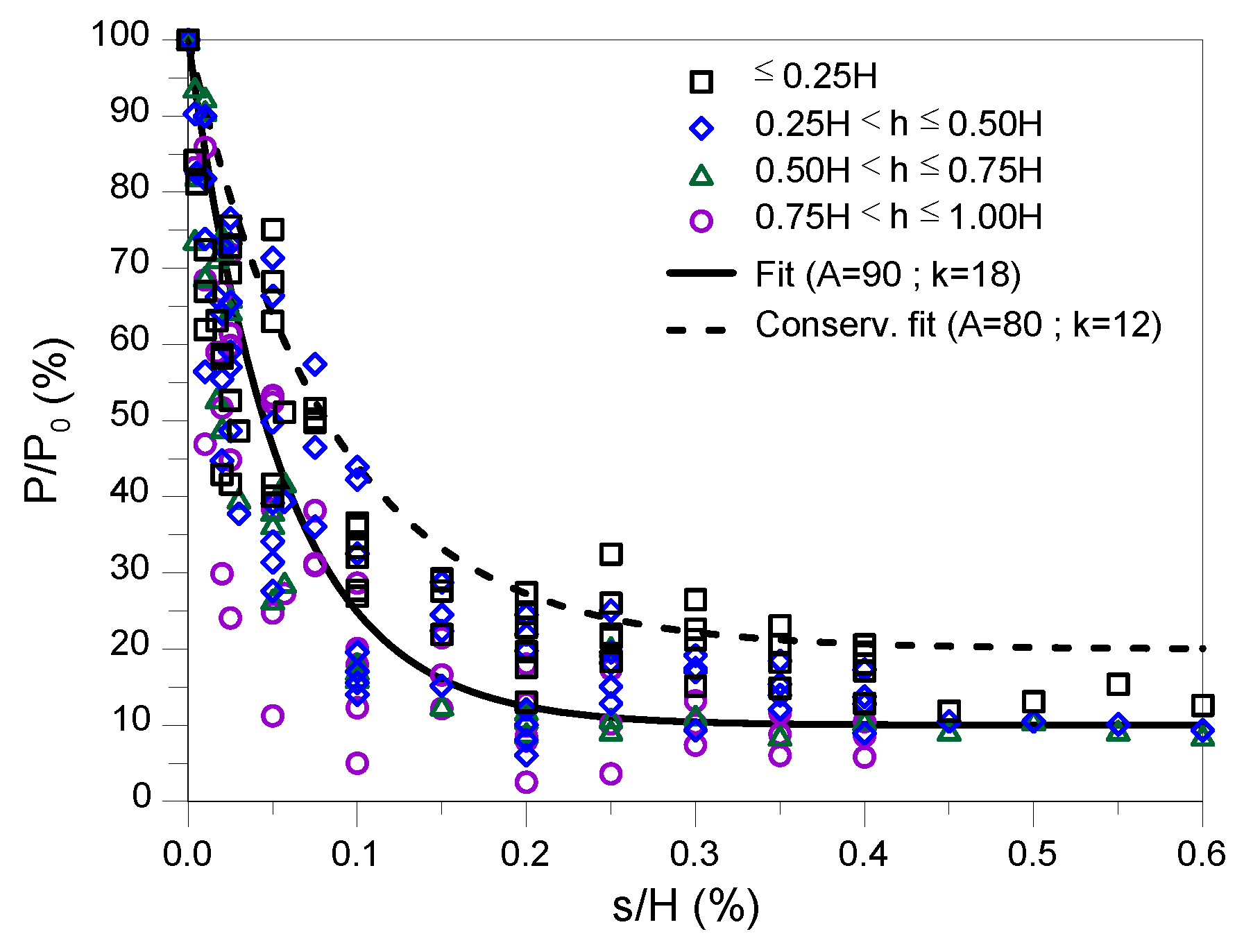
Figure 4 the points depicted in
Figure 3 for all four studies are replotted, normalized by the initial pressure (
), and grouped by depth to investigate if the earth pressure – displacement relationship was significantly impacted by the shaft depth. Clearly, while a trend is visible in
Figure 4, with an increase of the earth pressure reduction with the depth of the shaft, the effect can overall be considered limited. To strengthen the simplicity of the proposed method, it was decided to disregard any shaft depth effect, though this should be revised in future work if additional data is obtained exhibiting a clear depth dependency.
Based on the results plotted in
Figure 4 an expression to calculate the reduction factor of the normalized earth pressure (
) as a function of the normalized shaft lateral displacement (
) was fitted. Given the data distribution, an initial sharp reduction of the earth pressure and its asymptotic value for large shaft lateral displacements, it was decided to select an exponential expression with decreasing form (Equation 5).
The proposed equation depends on two parameters,
, which is the asymptotic value of the normalized earth pressure reduction and
, which controls the decay rate. For the gathered data values of
and
can be considered adequate as shown in
Figure 4 by the black solid line. Also, in the figure is represented a black dashed line, with parameters
and
, which can be adopted as a conservative fit. With the proposed curve a maximum earth pressure reduction of 90% is reached while the active limit state is achieved for approximately
.
Established the relationship between the normalized earth pressure and the normalized shaft lateral displacement the earth pressure distribution can be determined. As seen in
Figure 2 the initial stresses are usually well reproduced by Jaky’s [
33]
proposal and the earth pressure at active limit state is also adequately predicted by Berezantzev [
16] analytical solution. Consequently, Equation 6 is proposed to calculate the earth pressure having those upper and lower limits, respectively.
In the equation
and
correspond to the earth pressure determined by Berezantzev [
16] and Jaky’s [
33] proposals, respectively, which can be determined using the Equations presented in
Appendix A.
is the reduction factor calculated using Equation 5,
is the asymptotic parameter and
is a fitting coefficient, which is recommend to be equal to 2.
The validation of the proposed methodology was performed by comparing the predicted values against the data shown in
Figure 2 for all four studies. In
Table 3 the
calculated for all normalized shaft lateral displacements are presented. For comparison the values of
and
determined using Equations 1 and 2 proposed by Liu [
21] are also shown.
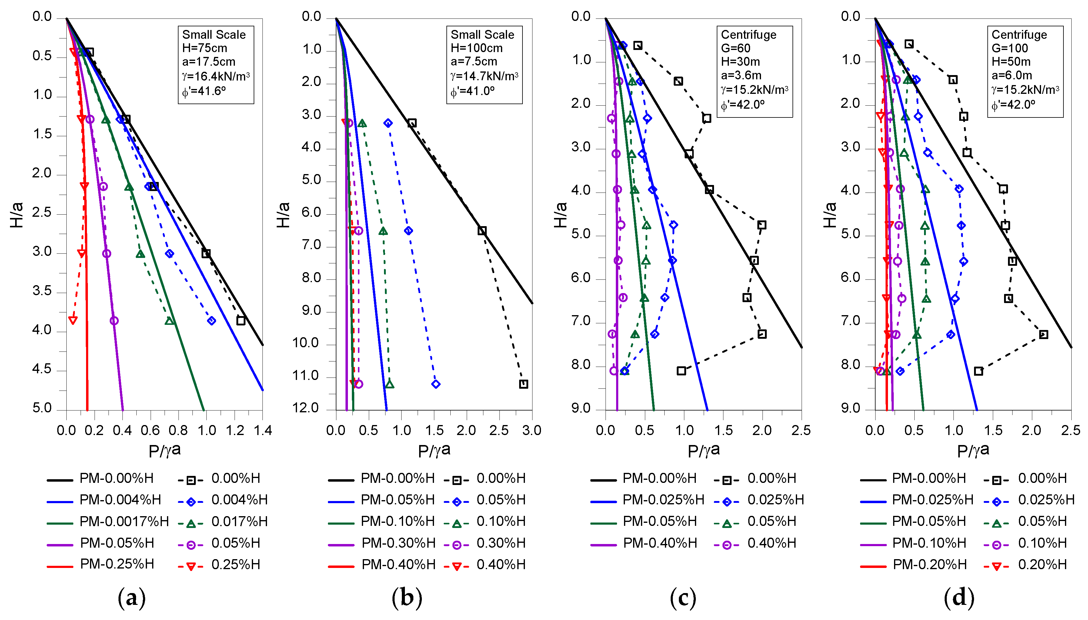
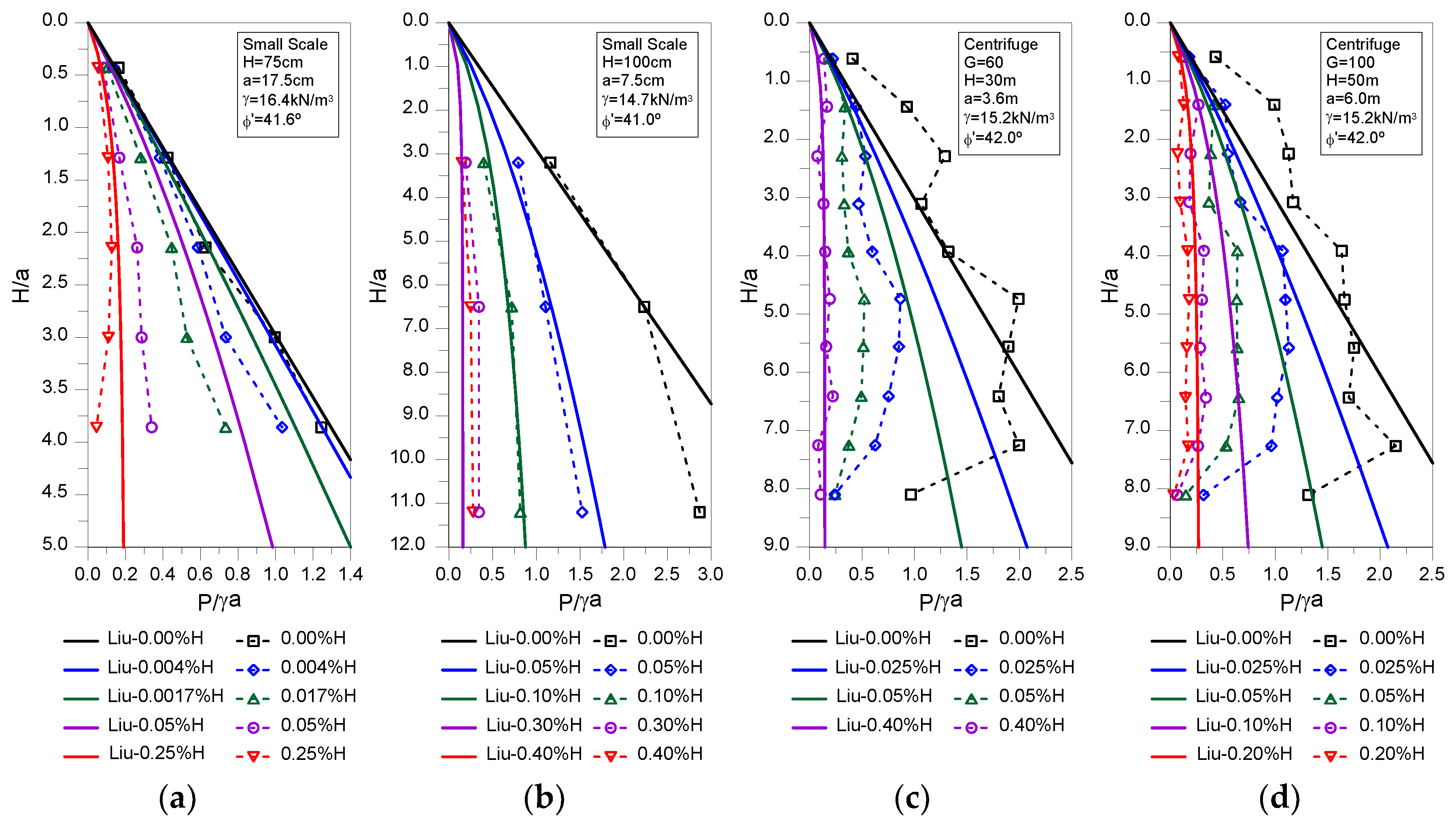
The predictions using the proposed methodology and Liu [
21] analytical solution are shown in
Figure 5 and
Figure 6, respectively, against the results of the relevant physical models. Overall, both methods can effectively predict with reasonable agreement the evolution of the earth pressure distribution with depth for the different shaft settlements in all studies. From
Figure 4 it is clear that Liu [
21] analytical solution tends to over-estimate the earth pressures, while the proposed methodology, apart from the Tobar and Meguid [
36] case, where a strange behavior was observed as discussed previously, presents a better agreement. This is confirmed by the results presented in
Table 4, where the root mean squared error (RMSE) is calculated for each case and shaft settlement using the following equation:
where
is the number of datapoints reported for each shaft lateral displacement, while
and
are, respectively, the earth pressures determined by the analytical solutions and those observed in the physical models. Clearly, smaller values of RMSE, corresponding to a closer fit between the prediction and the observed data, are obtained for the proposed methodology making it more suitable for predicting the earth pressure acting on circular shafts as a function of the shaft normalized lateral displacement.
5. Conclusions
The prediction of the earth pressures acting on circular shafts is a relevant topic, as shown by the significant number of studies published on the topic. Throughout the years several analytical expressions based on different frameworks have been proposed but all of them present limitations, such as the adoption of a constant circumferential stress ratio and, more relevant, the assumption of an active limit state, which requires large shaft lateral displacements to occur. As shown by field cases and numerical studies, the latter condition is often not verified in common practice, since the excavation methods employed, and the rigidity of the lining, restrict considerably the ground movements. As a result, the use of those analytical solutions leads to non-conservative predictions of the earth pressures, which might result in safety hazards. The only known method to account for the shaft lateral displacements on the earth pressure prediction was proposed by Liu [
21], but as the author acknowledges the relationships established between circumferential stress ratio and the mobilised friction angle require further refinement and validation.
In this article a new methodology to estimate the earth pressure acting on circular shafts as a function of the lateral displacement is proposed. Having as reference the results of relevant physical tests an equation that relates the reduction of the normalized earth pressure with the normalized lateral shaft displacement is established. Sequentially, the earth pressure can be estimated though Equation 6, which has as upper limit the initial pressure defined by Jaky’s [
33]
proposal and as lower limit the prediction made by Berezantzev [
16] analytical solution. The validation against the physical tests results shows a good agreement with the measured data and provides a better prediction that the method proposed by Liu [
21]. However, it should be noted that the proposed methodology was validated against the results of physical tests that were performed in sandy materials and where a uniform lateral deformation was imposed along the shaft height, which mighty be unrealistic in real cases. Nevertheless, as despite these limitations, it is believed that with the methodology proposed it is possible to predict more adequately the earth pressure acting on circular shafts, with the obtained results being acceptable for preliminary design stages.
