Submitted:
12 August 2024
Posted:
12 August 2024
You are already at the latest version
Abstract
Previous reviews by the authors [1, 2] indicate the continuing development and improvement of thermal protective systems through the introduction of polymer nanocomposites into polymer matrix composites. These materials perform as thermal protective systems for a variety of aerospace applications, such as thermal protection systems (TPS), solid rocket motors (SRM) nozzles, internal insulation of SRM, leading edges of hypersonic vehicles, and missile launch structures. A summary of the most recent, global technical research is presented. Polymeric resin systems continue to emphasize phenolic resins and other materials. New high-temperature organic resins based on phthalonitrile (PN), and polysiloxane are described and extend the increased temperature range of resin matrix systems.
Keywords:
ablatives
; polymer nanocomposites
; nanoparticles
; thermal protection systems
; hypersonic vehicles
; aerogels
; phthalonitrile
; polysiloxane
; infrastructures
; ballistics
1. Introduction
Thermal Protective Systems char and erode during exposure to excessive heat to deliver protection to the underlying components and prevent catastrophic failure. Improvements in thermal insulation, ablation resistance, and lightweight characteristics are the stimuli for continued developments in TPS. Polymer Nanocomposites (PNCs) and related Nanotechnology techniques are prominent in providing distinctive features as TPS resin matrix modifiers, as well as surface treatment of TPS fiber reinforcement by supplying thermal resistance, lower density, and mechanical strength. The recent application of aerogel technology to TPS has facilitated further utility of Nanotechnology [3]. Aerogels are nanostructured ultra-lightweight nanoporous materials with skeletal frameworks that display a wide range of nanomorphologies. They are solid materials composed of a network of pores which makes the material very lightweight and porous. The pores in aerogel act as insulators, preventing the transfer of heat through the material. Additionally, the low thermal conductivity of the gas trapped in the pores also helps to dissipate heat. This makes aerogel an ideal material for use in insulation and heat dissipation applications – both of which are critical to TPS. These interrelated aerogel areas that apply to TPS are discussed in this publication.
2. Resin Matrix and Reinforcement Systems
Phenolic resins continue to be the most desirable matrix resin in the development of TPS systems especially as it relates to the emergence of aerogel modification of the matrix resin. Boron modified phenolic resins are considered as well as closely related polybenzoxazine resins. New high temperature resins consist of a polysiloxane resin and a phthalonitrile resin material. Reinforcement fibers, such as woven fibers based on carbon fiber and quartz fiber are discussed in phenolic resin modification with nanomaterial additives. Low density, high porosity carbon fiber and/or quartz fiber needled felts or non-wovens are the popular reinforcements used in aerogel description.
2.1. Phenolic Resins as Matrix Resin
Niu and co-workers [4] utilized modified boron phenolic resin with the in-situ preparation of trisilanolheptaphenyl POSS (Figure 1) to obtain the heptylphenyl POSS modified boron phenolic resin (POSSBPR).
Figure 2 illustrates the preparation of the modified boron phenolic resin with the heptaphenyl POSS followed by impregnation of high silica fiber, curing under temperature conditions shown in Figure 2. The resulting POSSBPR composition varied from 0 to 25% POSS was used as an ethanol solution to impregnate silica fiber, followed by curing and molding. FTIR and NMR-29Si confirmed the POSSBPR structure. Char yield at 1,000°C increased from 68.1% to 74.2% for POSSBPR containing 20% POSS. The linear ablation rate and mass ablation rate for POSSBPR4/silica fiber were 0.123 mm/s and 0.0602 g/s as compared to BPR/silica fiber control values of 0.130 mm/s and 0.0685 g/s, respectively using oxyacetylene test bed (OTB) conditions of 4,186.8 kW/m2 (418.68 W/cm2) for 20 sec with sample dimensions of 30 mm diameter and 10 mm thickness. The authors attribute the improved reduced linear ablation rate and ablation mass rate to the formation of high graphitized carbon microstructure and high temperature ceramics from high temperature treatment of POSSBPR, especially the POSS component.
Yang and co-workers [5] dispersed a constant amount of MoSi2 to boron phenolic resin (0.57 to 0.43) and varied B4C into boron modified phenolic resin in ethanol and impregnated carbon fiber fabric with the resulting uniformly mixed “ceramizable” boron phenolic resin solution. Both MoSi2 and B4C were µm size. The prepregs were molded/cured into “ceramizable” composites. The overall process is shown in Figure 3.
Thermogravimetric analyses (TGA) of the “ceramizable” composites were carried out at 10°/minute in air up to 1,400°C. The highest char yield of 32.9% was observed for sample BP-15 which contained 15% B4C with a corresponding ratio of 0.57 to 0.43 of MoSi2 to boron phenolic resin. The overall stoichiometry is 15 parts B4C, 65 parts MoSi2, and 50 parts of boron phenolic resin in 50 parts of ethanol. It is indeed a ceramizable resin system with ~ 62% of ceramic additives. The authors propose that the high char yield is attributable in part to B4C reacting with oxygen at elevated temperature to form B2O3 which increases char yield. The flexural strength of the ceramizable composites was determined at elevated temperatures of 800°C/15 minutes, 1,000°C/15 minutes, 1,200°C/15 minutes, and 1,400°C/15 minutes. The best flexural strength properties during the range of temperatures were exhibited by BP-15 which contained 15% B4C. The unexpected small reduction in diameter size of carbon fiber in the ceramizable composites was shown by the authors to be responsible for observing continued high flexural strength especially for the resulting diameter size of BP-15. The carbon fiber diameter of BP-15 was 7.118 µm (Table 1) initially at RT and reduced to 6.681 µm after successive temperature treatments from 800°C, 1,000°C, 1,200°C, and 1,400°C with 15-minute intervals.
A control of carbon fiber exposed to similar temperatures conditions up to 1,400°C in air with 15-minute intervals showed that the diameter reduced from 7.118 µm to 4.863 µm and indicative of thermal instability of carbon fiber in air at elevated temperature as well as reaction with ceramic additives.
Regarding the reduction in carbon fiber diameter of other composites with less or no B4C, such as BP-0 which contains solely MoSi2 and boron phenolic resin, the carbon fiber diameter is 6.042 µm after multiple temperature increases and multiple 15-minute intervals. Morphology and XRD analyses of composites suggest that MoSi2 derived complex phase ceramics, such as MoB, MoB2, Mo2C, Mo4.8Si3C0.6, etc., with high melting points were formed at high temperatures. The formation of B2O3 and the MoSi2 – derived complex phase ceramics participated as oxygen barriers and minimizing the oxidation or reduction in carbon fiber diameter and enhancing the performance of composites at elevated temperatures. Ablation data were reported for linear and mass ablation rates without indicating OTB test conditions. Nevertheless, the lowest linear ablation rate was 0.013 mm/s for 20% B4C as compared to 0.0424 mm/s without B4C particles. The lowest mass ablation rate of 0.0815 g/s was recorded for the composition containing 15% B4C while the 20% B4C was higher, or 0.0840 g/s. Authors attribute this discrepancy to 2 factors, such as oxidation of B4C is a weight gain reaction while the volatilization of B2O3 is a weight loss process. A compromise between weight gaining and weight loss processes occurs with 15% B4C particles as compared to 20% B4C. The authors viewed BP-15 which contained carbon fibers, boron phenolic resin, MoSi2 and B4C particles exhibiting excellent high temperature behavior.
An interesting publication by Li and co-workers [6] describes the Z – pinning effect on interlaminar mechanical and ablation performance of quartz fiber/phenolic composites. The objective of the study was the reinforcement of the composite interlaminar properties by Z pinning. Z pinning has been successful in significantly improving type I and type II fracture toughness and interlayer composite properties. Multi-ply quartz fiber prepreg was fabricated with Z pins made of quartz fiber and phenolic resin. Z-pins were implanted into the prepregs by ultrasound methodology followed by curing from 100°C to 180°C for multiple hours. The interlaminar effect of Z pins on composite depends on the bonding interface that is mainly due to cured resin. The pyrolysis of the phenolic resin via TGA exhibited a weight loss rate of 14.38% at a temperature of 920°C in an atmosphere of 20/80 for O2 to N2 for 60 seconds indicative that the Z pin and laminate interface maintain the interface bridging bond after flame ablation. After 60 seconds of ablation in a flame of 920°C, the interlaminar shear strength of the Z pin reinforced composites was 3.01 Mpa, 84.7% stronger than that of the control. During the ablation process, the Z-pins effectively suppressed the interlaminar delamination and the formation of large areas of bulges by enhancing the interlaminar strength and providing escape channels for the pyrolysis gas. Thus, it was demonstrated that Z-pin can effectively prevent mechanical erosion of the ablation surface and improve composite ablation performance.
2.2. EPDM Rubber
Xi and coworkers[7] examined EPDM insulation for solid rocket motors and introduced carbon nanotubes (CNT) to improve the strength of the composite insulation material since particle erosion occurs due to aluminized composite propellants striking the surface of the insulation material. CNT is known to enhance the strength of the char layer. Other investigators have shown that the network formed by CNT with EPDM enhances the mechanical properties of the char layer and reduces erosion caused by alumina particles. Furthermore, CNT promotes chemical vapor deposition (CVD) of pyrolysis gases in the char layer that strengthens the char layer. CNT improves ablation resistance of composite insulation by strengthening char layer but at the same time produces a negative effect on the reduction of the thermal insulation performance of the composite insulation material due to the high thermal conductivity of CNT. The use of CVD to coat CNT based on earlier work of CVD of CNT improved the compatibility of coated CNTs in EPDM. CVD coating of the CNT increased the diameter from 10-20 nm (uncoated) to 55-60 nm for coated CNT. In all cases mechanical properties (strength and elongation) of uncoated CNT formulation was highest followed by coated CNT, with the basic formulation (control, no added CNT) the lowest.
TGA results shown in Figure 4 indicate that in the initial stage of heating when the temperature is lower than 450°C, the weight loss of the basic formulation is more than that of the CNTs formulation and coated–CNTs formulation. See inset of Figure 4. This indicates that the thermal insulation material with added CNTs exhibits better thermal stability. When the decomposition temperature is reached, the residue amount of the basic formulation is 16.9%, while that of the CNTS formulation and coated-CNTs formulation are 21.7% and 21.1%, respectively. Similarly, material conductivity, ablation rate, back side temperature, all followed a similar trend. Highest values were exhibited by uncoated CNT, followed by coated CNT with the control showing the lowest. The char layer of the coated CNT showed the best compression resistance followed by the CNT formulation. Control was quite inferior. The microstructure of the surface and cross section of the char layer showed a compact structure with no pores on the coated CNT while the CNT formulation is relatively compact with some small pores. The control exhibits a loose pore structure with large pore size. Thus, thermal insulation performance of coated CNTs provides greatly improved performance compared to uncoated CNTs. Further, the char layer of the coated CNT formulation not only improves thermal insulation but also provides better compressive resistance. These two characteristics indicate that the coated CNT not only improves thermal insulation performance by reducing thermal conductivity of the formulation but also provides particle erosion resistance of the insulation materials by enhanced strength of the char layer.
A follow-up paper by the Guo group [8] involves a study related to the size and content of CNTs providing particle erosion resistance of EPDM. Different CNTs parameters of CNTs with different sizes are shown in Table 2.
A particle test motor was used in the study to investigate the particle erosion resistance of EPDM composites reinforced with different contents of CNTs with different sizes. The burning propellant produces molten Al2O3 particles forming a dense particle stream that impacts EPDM composite surface. Particle erosion resistance is determined by measuring thickness and mass values before and after the motor experiment. CNT content and size significantly influence the particle erosion resistance of the EPDM composites. The study showed that EPDM composites with a CNT content of 10 phr exhibited the best particle erosion resistance; the ablation rates of EPDM composites with lower (2 phr) or higher (20 phr) CNT contents were significantly higher. Further, long CNTs with excellent mechanical properties greatly improved the particle erosion resistance of the EPDM composites. The charring rate was 43.6% lower than that of conventional CNTs. Furthermore, EPDM composites containing large diameter CNTs showed poor mechanical properties, high thermal conductivity, and low generation of pyrolytic carbon (carbon generated by CVD to strengthen the char layer) resulting in poor particle erosion performance.
2.3. New Thermosetting Resins
The heritage thermosetting resin since the inception of TPS has been the phenolic (PF) resin and has been modified structurally by insertion of boron, silicon, and other inorganic elements or the use of additives (ceramics and nanoparticles) as well as related phenolic resin systems, such as benzoxazines and cyanate esters. Notably PF possesses unique features, such as reasonable char yield of 62%, exceptional thermal stability on conversion to carbon/carbon composite at elevated temperatures, low viscosity/low MW reactive resin system, relative ease of transforming into desired aerogel (discussed later in this paper), and readily available at a reasonable cost. A large database has been generated by NASA and the US Department of Defense (DoD) branches depending on the utility of the resulting phenolic TPS application. Global efforts ©nvolving phenolic resins for TPS ©©e activities in Europe and Asia.
New thermosetting resins that are improvements over phenolic resin consist of polysiloxane and phthalonitrile resin.
Polysiloxane: One of the new high temperature thermosetting resin systems is a novel polysiloxane, known as UHTR 6398-S, a solventless resin manufactured by Techneglas, Perrysburg, OH [9,10]. UHTR is a colorless, semi-solid liquid that can be thermally cured at 350°C/2 hours or catalyzed with small amount of base. Figure 5 shows the structural formula of UHTR resin properties, and its comparison with other high performance thermosetting resins [11]. As a carbon fiber UHTR composite, the CF/UHTR composite possesses a char yield of 93% (TGA) as compared to CF/phenolic resin composite (MX4926, carbon fiber phenolic resin composite) exhibiting a value of 83% in nitrogen (Figure 6) [12].
Char yield is defined as the weight of material at 1,000°C divided by its weight after isothermal period in nitrogen environment using a heating rate of 20°C/min. However, in air, the UHTR composite retains 25% char while the CF/phenolic is completely decomposed, further demonstrating the superior thermal stability of UHTR over phenolic resin (Hou et al., 2022) [12]. Using a hot melt process CF/UHTR prepreg is cut into 1.27 x 1.27 cm. squares (Figure 7) and molded into a cylindrical disc measuring 7.62 cm. diameter and 1.27 cm. thickness with post-curing the disc at 350°C/2 hours. The resulting disc is subjected to OTB testing in the KAI laboratory.
Koo and his KAI team have been engaged in the development of many thermal protective ablative systems involving preparation, testing, and modeling for nearly two decades. These KAI activities have been summarized recently [13]. OTB results are presented as recession and mass loss percentages, surface, and backside temperatures versus ablation parameters. Ablation parameter is defined as the product of heat flux X exposure time (heat load input). Table 3 shows typical OTB test conditions for the KAI team uses to evaluate TPS materials.
Recession percentages of the CF/UHTR MC and MX4926N MC materials over ablation parameters are shown in Figure 8.
The shaded areas represent the error range. Ablation parameter is defined as the heat flux multiplies the time that the material exposed to the OTB flame; this represents the heat load imposed on the material. Both materials present negative recession percentages at all tested conditions and implies the materials have swelled more than receded during the OTB aerothermal tests. To separate the swell and material loss, the mass losses of both materials are plotted as ablation parameters, as shown in Figure 8 (b). Figure 8 (b) shows that the mass losses of both materials increase as the ablation parameter increases. The shaded areas represent the error range. Mass losses of the CF/UHTR MC are approximately 1/8 of those of the MX4926N MC material in all test conditions, which indicates that the CF/UHTR MC has better ablation resistant property than the MX-4926N MC. Figure 9 shows the top surface temperatures and the backside heat-soaked temperatures of CF/ UHTR MC and MX4926N MC in the OTB ablation tests. Temperatures of both materials are similar in all testing conditions. Surface temperatures of both materials have reached above 1,800°C, the backside heat-soaked temperatures of both materials have remained below 250°C. These results indicate that both materials have incredibly good thermal insulation property.
Polysiloxane resin is known to be a precursor to silicon oxycarbide composition (SiOC) when pyrolyzed at temperatures from 1,000-1,500°C (1,832-2,732°F). Silicon oxycarbide is a hard glass, structurally related to both silica and silicon carbide. It is of considerable research interest because of its high mechanical and dielectric properties, its interesting viscoelastic behavior at elevated temperatures, and its superior oxidation resistance in comparison to silicon carbide due to surface passivation with SiO2. The use of silicon oxycarbide composition is mentioned in the aerogel discussion later.
A novel class of alumina-reinforced, pre-ceramic resin matrix ablative composites was developed, manufactured, characterized, and modeled for use as a TPS material by C. Yee [14]. High alumina paper and twill-woven mullite fiber were investigated as reinforcements for a Techneglas Ultra High Temperature Resin (UHTR) [9,10] pre-ceramic polysiloxane matrix composite. These 2D laminate alumina/UHTR (A/U) composites minimize peak back face temperature primarily through rapid melt advection and low through-thickness thermal conductivity. A loading study was performed for boron carbide (B4C) as an additive and identified an optimal 7.5 wt% loading in UHTR, and the resulting changes to decomposition chemistry mechanisms were identified using analytical chemistry techniques. The bulk formation of networked Silicon Boron Oxycarbide (SiBOC) and precipitation of Highly Oriented Pyrolytic Graphite (HOPG) was identified in pyrolyzed and annealed UHTR with boron carbide. Four variants of A/U with and without boron carbide underwent aerothermal testing using the OTB, whose flow field was characterized using Schlieren imaging and a low-cost enthalpy probe. Alumina Paper/UHTR with 7.5 wt% B4C (AP/UBC) was down selected to be the primary focus of thermal characterization and ablation material response (MR) modeling efforts in CMA, FIAT, and ITRAC, three industry standard one-dimensional ablation modeling codes. Ablative software outputs were compared against OTB experimental results to validate the AP/UBC material response model for use in preliminary design estimates for AP/UBC thicknesses of 0.100 inches or less.
All A/U composites were tested three times each at a cold wall heat flux of 1,000 W/cm2 for 30 s. This time was chosen after prototype testing in order to prevent excessive ablation crater formation, which results in straying from pseudo-1D heating conditions due to the change in surface geometry and can additionally extinguish the torch flame through turbulent backchanneling of exhaust. The test conditions also fall into standard time and cold wall heat flux test conditions for the OTB, permitting direct comparison of the A/U composite ablative performance against other materials tested on the OTB. The conditions are roughly comparable to the environment potentially experienced by a tactical scale solid rocket motor nozzle component or launch structure TPS element. Final modeling efforts were focused on AP/UBC based on its consistent performance, low back face peak heat soak temperatures, long time to peak back face temperature, and novel decomposition chemistry. In order to aid in the validation of the material model’s thermal properties, additional tests for AP/UBC were performed at 500 W/cm2 for 30 seconds to provide different recovery temperatures and thermochemical environments.
A summary of average ablative testing metrics and their standard deviations are presented for all A/U composites in Table 4. The recession is based on post-test depth caliper measurements. Both woven mullite fiber reinforced composites exhibited similarly high recession levels due to advection behavior being dominated by the high fiber mass ratio. AP/U demonstrated the lowest peak back face heat soak temperature and longest time to heat soak conditions, while AP/UBC had the lowest recession of all A/U composites.
The 11 AP/UBC test models produced also achieved a consistent 88:12 resin: fiber post-cure weight ratio. Representative temperature profiles as well as testing images are shown in Figure 10. AP/UBC demonstrated slightly higher back face peak heat soak temperatures than AP/U but otherwise performed similarly during OTB testing. Despite the observed brittleness of SiBOC in alumina paper, charred AP/UBC samples exhibited decent toughness and did not delaminate or crumble when removed from the insulative alumina crucible.
AP/UBC was extensively characterized using both analytical chemistry and thermal characterization instruments in order to fully understand how the material decomposed and how that decomposition would affect the thermal properties during ablation. Analytical chemistry primarily focused on determining the pyrolysis gas and char atomic compositions for thermochemistry modeling, as well as positively identifying SiBOC as forming within the pyrolysis zone of the AP/UBC after 500°C. TGA-FTIR and EDS were utilized to quantify the pyrolysis gas and char composition, while TGA-DTA, FTIR, Raman spectroscopy, and XPS were utilized to identify the SiBOC formation. Additionally, micro-CT was performed at Lawerence Berkeley National Laboratory (LBNL) at the Advanced Light Source (ALS) Beamline 8.3.2 [15], with results demonstrating the changes between virgin AP/UBC and pyrolyzed material as shown in Figure 11.
Fully cured UBC is a networked polysiloxane containing distributed boron carbide crystals with limited boron oxide. During initial heating, boron carbide near the exposed surface oxidizes and eventually melts at approximately 450°C. Starting at 525°C, the UHTR decomposes into amorphous SiOC, which reacts with available boron carbide and boron oxide to produce amorphous SiBOC and precipitate a limited amount of HOP graphite. Water, CO, CO2, butanol, benzene, methane, and leftover trapped IPA from the boron carbide dispersal process are emitted as a pyrolysis gas, with some of the mass loss mitigated by uptake of environmental oxygen and subsequent incorporation within the SiBOC matrix. Mass gain due to uptake of oxygen overcomes mass loss from pyrolysis at approximately 675°C. In an environment lacking oxygen, nitridation of boron carbide will occur, leading to a lesser total mass gain. The SiBOC then further chemically bonds to the alumina reinforcement, forming AlSiBOC at the resin-reinforcement interface, greatly increasing the thermal and electrical conductivity of the pyrolyzing composite. The AlSiBOC and SiBOC undergo phase separation and limited melting starting at 1,400°C, with the rate of phase transition to liquid for both the matrix and reinforcement peaking at approximately 2,100°C. A graphical timeline of the A/U composite decomposition process is presented in Figure 12.
Four alumina-reinforced, preceramic polysiloxane resin matrix TPS composites with a density range of 1.04 to 1.34 g/cc were designed, fabricated, and tested under an aerothermal ablation environment in order to demonstrate their feasibility. Based on OTB aerothermal testing, the best performing system was down selected for further characterization and modeling. Alumina paper reinforcement in combination with Techneglas UHTR was identified as the best performing ablative during OTB testing, both with and without added boron carbide flakes. Boron carbide was shown to be highly effective as an oxidative barrier and resulted in broad changes to overall decomposition chemistry, trading off a slightly higher peak back face heat soak temperature for better shape stability compared to a neat UHTR matrix. The resulting preliminary engineering designed models exhibited decent agreement with near-surface temperature response, mass loss, and recession, with FIAT demonstrating the best overall temperature profile predictions for both 1,000 and 500 W/cm2 conditions in the OTB. The AP/UBC model demonstrated good validity for preliminary design estimate purposes for thicknesses at or below 0.100-inch.
In the author’s conclusion, the author recommended OTB flow field characterization can be improved through the use of designed gas analysis systems rather than utilizing COTS handheld sensors. This will also significantly improve the workflow of enthalpy probe operation due to requiring fewer tooling changes. A sensor designed to measure high NOx concentrations will be necessary to this end, and measuring the distribution of NOx within the flow will provide better data for surface thermochemistry inputs as well as CFD modeling of the flow field. Alternatively, gas samples could be drawn from the enthalpy probe and shipped to a mixed gas analysis service provider. Varying oxygen and acetylene flow rates to characterize different flames using the enthalpy probe would be a worthwhile endeavor for CFD and combustion modeling validation data, as well as for studying NOx production and consumption rates in an open flame. In order to safely sample gas from the outer combustion zone and at stations above 500 W/cm2 cold wall heat flux, it will be necessary to design and build a custom enthalpy probe capable of withstanding the extremely high temperature as well as being designed around preventing steam binding of the cooling lines, either through use of a pressurizer design or high flow rate in a vertical orientation, with both options requiring significant expense in order to achieve and maintain. This upgraded enthalpy probe would be additionally useful for characterizing any oxy-fuel flame due to its ability to withstand the high temperatures of oxyacetylene combustion.
Phthalonitrile: The other new thermosetting resin for TPS is phthalonitrile resin (PN). Early synthesis activity involved the efforts of Keller [16,17,18] of the US Navy Research Laboratory and Zhou et al. [19]. Recent phthalonitrile resin books [20,21] describe the extensive chemistry of phthalonitrile resins, composites, and applications.
Although PN resin possesses attractive thermal properties, there has been limited ablation data reported in the open literature thus far. Preliminary ablation studies conducted by Yang et al. [22] involve the use butane flame with moderate heat flux. According to the authors the butane flame technique is more convenient to adjust and more economical than OTB testing. The overall process involving the CF/PN composite laminate is shown in Figure 13. The PN structure, hot-pressing curve and specimen lay-up illustrate the characteristics of the laminate.
PN with a carbon fiber (CF/PN) volume fraction of 41.7% was examined by butane flame method [22]. The resin on the laminate surface significantly decomposes under one-sided flame heating. The degree of resin pyrolysis at deeper depth appears relatively small, while the remaining matrix forms a loose porous structure. The different morphologies at various positions along the thickness gradient emphasize the influence of different gas environments on pyrolysis behavior. A phenomenological mathematical model with high reliability is proposed based on FE simulations to quickly predict the rear surface temperature of CF/PN composite laminate under one-sided heating, which provides preliminary engineering guidance oriented to thermal protection/load-bearing integration structural design.
Blends of phenolic novolac phthalonitrile (NPN) with novolac cyanate ester (NCE) were examined recently using plasma arc jet ablation conditions [23]. The NPN was prepared by reacting phenolic novolac with 4-nitrophthalonitrile to form NPN. CE was obtained from Lonza Chemicals, USA. NPN and NCE were prepared in different weight ratios (1:3, 1:1, 3:1) and cured according to a schedule of 150°, 200°C, and 250°C for 1hr each followed by 300°C/2hr and 350°C/3hr. Blends exhibited a two-phase morphology with PN domains distributed as different sized spherical structures dispersed in a continuous cured CE matrix as evidenced by SEM and AFM. Chopped silicon fiber composites with 3M micro-balloons and NPN:NCE blends were transformed into molded composites with densities of 0.50 +/- 0.02 g/cc. The cured resin blends and composites were pyrolyzed at 1,000°C to form polymer-derived ceramics. Thermal conductivity of the composite samples showed a marginal increase from 0.11 W/m-K to 0.14 W/m-K at 80°C with increase in PN content in the blend. The flexural and compressive properties indicated that the composites exhibited good strength and modulus values. All the composites showed excellent thermal stability with extremely high char yields in the range of 75-81% at 900°C. Percent retention of compressive properties with increasing PN concentration varied from 30 to 55% and agrees with char values. Exposure of the composites to very low re-entry heat flux condition and extremely exposure time using radiant heating conditions (~55 W/cm2 for 1,200s) and Plasma Arc jet (70 and 125 W/cm2 for 50s) resulted in excellent surface uniformity with minimal mass loss (4.77–5.77%) and excellent heat of ablation (8.000–12,000 cal/g) with reduced back-wall temperature (230–260◦C).
4. Phenolic Resins—Transformation into Aerogel
It was mentioned previously that the use of aerogels to further modify TPS for improved performance has become a high priority activity in recent publications. Aerogels provide very efficient insulation due to their high porosity with light weight pore structure in the nanometer range. They are proficient in insulation because the pores are so small that gas phase heat conduction is extremely poor resulting in limited heat transfer through the material. Aerogels appear to be an ideal modification material for TPS due to high porosity, light weight, low thermal conductivity, improved thermal stability, improved mechanical properties, and low dissipation of heat transfer. Recent aerogel reviews by Salimian [24], Liu [25], and the more recent review by Jin [3] which discusses aerogels for TPS are available to provide an overview of aerogels.
As a nanoporous material with ultralow conductivity, aerogels have attracted considerable interest in applying the technique to TPS for aerospace. Aerogels encompass a wide range of compositions such as, 1) Inorganic oxide aerogels and composites for thermal protection – SiO2, Al2O3, ZrO2, multi-oxide like Al2O3/SiO2, ZrO2·SiO2 some of which have been examined in aerospace applications. 2) Organic aerogels and composites for thermal protection – phenolic resin and polyimide. 3) Carbon aerogels and composites for thermal protection. 4) Carbide (SiC and other carbides) aerogels and composites for thermal protection. However, SiO2, silicon oxy carbide, phenolic resin and/or silica hybrids, and carbon aerogel will be discussed as aerogel components.
This review will focus on organic aerogels for TPS. As best as it can be determined, the first reported use of an organic aerogel in TPS was conducted by Cheng and co-workers in 2017 [26]. PAN-based carbon fiber needled felt (NCF) with dimensions of 48- x 48- x 24-mm3 and density of 0.164 g/cc was immersed into a solution of phenolic resin (PR), 66.7% in isopropanol, hexamethylenetetramine (HMTA), and ethylene glycol (EG). Four solutions with different phenolic resin concentrations of weight ratio of PR to EG of 1:5 (sample PR1/5), 1:4 (PR1/4), 1:3 (PR1/3), and 1:2 (PR1/2) were prepared. The resulting systems were heated from 90°C to 180°C for multiple hours leading to phase separation of the phenolic resin followed by curing into phenolic aerogel. The resulting impregnated aerogel CF felt was immersed into ethanol at 60°C for 48 hours to remove EG. The resulting NCF-PR aerogel composites with densities of 0.27 – 0.37 g/cc were designated as NCF-PR1/2 through NCF-PR1/5.
Figure 14 illustrates the overall procedure. Micrographs [Figure 14 (b) and (c)] of the composite show that the CF of NCF in the xy direction are distributed disorderly in plane, while in the z direction the main part of the fibers are uniformly distributed over the height of the composite. These CF are tangled and restrained to form an integrated and quasi-layered structure forming the NCF-PR aerogel composite anisotropic in these two directions. The high magnification images [Figure 14 (d) and (e)] show the PR aerogels as uniform and completely fill the macropores between CF and are coated with a thin layer on the fiber surface. The authors emphasize that the micrographs show a homogeneous PR aerogel matrix without fracture and indicate that agglomeration of pores is achieved. Further a composite is obtained that is lightweight and superior in adhesion at the fiber/resin interface. The authors’ view the composite aerogel as a “bird’s nest structure.” The microstructure of the PR aerogels exhibits typical bi-continuous and percolating structures of aerogels prepared by “polymer induced phase separation” (PIPS) that most of the volume consists of interconnected pores, consisting of interconnected grape-like aggregates. When the content of PR resin increased from PR1/5 to PR1/2, aerogel particle size decreased from ~124 to 80 nm., with a narrow size distribution.
The NCF-PR aerogel composite possesses relatively high compressive strength (1.48 to 11.02 and 0.83 to 4.90 MPa in xy and z directions, respectively), and low thermal conductivity [0.131 to 0.230 and 0.093 to 0.180 W/(m-K) in the xy and z directions, respectively]. More importantly the NCF-PR aerogel composite exhibits good thermal insulation and ablation performance in an arc jet wind tunnel simulated environment [heat flux of 1.5 MW/m2 (115 W/cm2) for 33 s] with a low linear ablation rate (sample NCF-PR1/2 exhibited a linear ablation rate value of 0.029 mm/s and the lowest of all samples), internal temperature peaks below 90°C at 38 mm in-depth thermocouple position when the surface temperature exceeds 2,000°C. Thus, this early publication of a carbon fiber felt/phenolic resin composite aerogel suggested anticipated further publications with aerogel structural modification of the fiber reinforced composite systems with expected improved ablation performance.
Poloni and co-workers in Europe [27,28] provide some technical and theoretical considerations in the use of aerogels in the design of newer and improved TPS. Ablators that withstand intense thermal radiation conditions for distant planets require the development of porous carbon ablators with pore sizes that enhance heat-shielding performance by increased scattering of high-temperature thermal radiation. The authors’ focus related to pore size and the development of porous materials, such as aerogels. The use of aerogels is directed to NASA Phenolic impregnated carbon ablators (PICA) which are unusual lightweight, ablators that consume part of the heat upon pyrolysis during re-entry into planetary atmospheres. PICA is prepared by using a carbon fiber felt to reinforce phenolic aerogels resulting in a highly porous structure (85%) with advantages, such as lightweight, excellent thermal insulation, attractive mechanical properties, high thermal stability, and dimensional stability. As demonstrated by Cheng et al. [26] for aerogel modified TPS, Poloni and co-workers used the PIPS procedure on phenolic resins to create pores with sizes ranging from 15 nm to 3 µm. Poloni et al.’s conditions were somewhat different than Cheng et al.’s procedure. Polyvinyl pyrrolidone (PVP) was used as an additive which is known to influence phase separation for the preparation of porous membranes. The formulation consisted of base catalyzed phenolic resin (PR) dissolved in ethylene glycol (EG) at resin to EG volume ratios of 1:2 to 1:7.5. The polymers were pre-dissolved in the initial solution at 110°C in PVP/PR ratios of up to 50%. The phase separation was induced by maintaining the polymer mixture at 150°C for 12 hours. A recent paper by Poloni et al. [28] describes the preparation of the High Enthalpy Flow Diagnostics Group (HEFDiG) material as HEFDiG Ablation-Research Laboratory Experiment Material (HARLEM) using PIPS technology with PR/PVP/EG technology as shown in Figure 15.
A comparison of electron microscopy images of HARLEM with a propriety European phenolic ablator, ASTERM, and NASA PICA is shown in Figure 16. HARLEM is found to be reasonably similar to ASTERM and PICA based on photomicrographs.
The ablation performance of HARLEM was determined via arc jet testing. Cold-wall heat flux of 5.4 MW/m2 (540 W/cm2) for 30 s was used and a recession rate of 48 µm/s. was measured in-situ by photogrammetry. The authors developed a relationship that considers the effective heat of ablation (heff) as it relates to cold-wall heat flux value divided by the product of the apparent density of HARLEM (0.27 g/cc) and the surface recession rate. An effective heat of ablation value of 417 MJ/kg was determined for HARLEM. Other effective heats of ablation for a variety of carbon-phenolic ablators tested in air at plasma wind tunnel facilities are tabulated by the authors and include ASTERM with values ranging from 65.7 to 182.6 MJ/kg as well as PICA with a wide range of values from a low of 43.5 to a high of 382.7 MJ/kg. PICA surface recession rates were higher than surface recession rates for ASTERM and HARLEM despite low densities of the carbon-phenolic ablators.
4.1. Phenolic Silica Hybrid Aerogels
Cheng and co-workers [29] modified their early phenolic aerogel study of 2017 [26] by co-curing phenolic resin with an aminosilane compound to develop a phenolic silicon (PSi) hybrid aerogel. A lightweight carbon fiber-quartz fiber needled felt (C-QF, 1:1) reinforced by phenolic-silica (C-QF/PSi) aerogel nanocomposite was prepared by impregnating low density C-QF hybrid needled felt with co-precursor solution of PSi hybrid aerogel, followed by co-polymerization induced nanoscale phase separation, solvent exchange and ambient pressure drying (APD). The overall process is shown in Figure 17.
The hybrid needled felt is based on T 700 PAN-based carbon fiber and quartz fiber with a volume ratio of 1:1 and a density of 0.352 g/cc with a high porosity of 81%. Synthesis of the PSi hybrid aerogels involved phenolic resin (PR), hexamethylenetetramine (HMTA), and ethylene glycol (EG) at a weight ratio of PR:HMTA:EG = 1:0.05:4, in solution followed by the addition of (3-aminopropyl) triethoxysilane (APTES). Weight ratio of APTES:PR is 0.25, 0.5, 0.75, and 1.0 with the corresponding samples known as PSi25, PSi50, PSi75, and PSi100. Individual solutions were transferred into a sealed vessel containing C-QF felt followed by vacuum impregnation of the felt and cured from 90°C to 180°C for multiple hours. C-QF/PSi with densities of 0.460 to 0.515 g/cc were obtained and known as C-QF/PSi x with x = 25, 50, 75, and 100 according to their aerogel matrix. SEM images of the C-QF/PSi quasi-layered fibrous architecture suggest that the C-QF/PSi is anisotropic in the xy and z directions. Higher magnification of SEM image revealed the fully and uniform distribution of PSi in the 3D interconnected pores of C-QF.
The authors concur that a highly porous felt was impregnated uniformly with aerogel without fracture. A detailed description of the PSi branched aerogel network using SEM, FTIR, and solid state 13C and 29Si NMR analyses supported phenolic cured functional groups by 13C NMR while 29Si NMR suggest phenolic hydroxyl reacts with the triethoxy group to form Si – O – C bond. FTIR spectra supported many of the proposed cured functional structures. TGA analyses of PR control exhibited a char yield of 55.45% versus a value of 60.79% for PSi100. The C-QF/PSi aerogel nanocomposite exhibited good mechanical properties, such as compressive strength that varied from 12.7 to 17.01 and 5.96 to 7.51 MPa in the xy and z directions, respectively. Thermal conductivity as low as 0.112 W/(m-K) was observed. More importantly good thermal ablative and insulative properties (linear ablation rate as low as 0.017 mm/s, internal temperature peaks below 100°C at 80 mm in-depth position when the surface temperature exceeds 2,000°C) using oxy-acetylene torch for 300s. The hybrid phenolic – silica aerogel did achieve improved ablation performance.
4.2. Phenolic Silicon Interpenetrating Aerogels
An unusual proposed interpenetrating aerogel nanocomposite based on silicon-oxy-carbide (SiOC) and phenolic resin was reported by the Zhang group [30]. The objective of the Jin et al. study was the improvement of the oxidation resistance of PICA like ablators due to the 3D interconnection of composite microstructure of those carbon containing materials, such as carbon fiber and phenolic resin which are susceptible to oxidation. A unique multiscale needled carbon fiber felt reinforced by silicon-oxy-carbide/phenolic interpenetrating aerogel nanocomposite was proposed as follows: the needled CF felt (NCF) was reinforced by SiOC by the sol-gel in-situ method on the felt. Phenolic aerogel was prepared and introduced into the voids of the felt-SiOC by vacuum impregnation and sol-gel phase separation induced by high temperature. The overall process is shown in Figure 18.
The preparation of SiOC aerogels involved the addition of methyltrimethoxysilane (MTMS) to dimethyldiethoxysilane (DMDES) in ethanol with various proportions of MTMS to DMDES with distilled water and ammonia. Needled carbon fiber felt was impregnated with the SiOC aerogel solution, placed in a sealed vessel, and heated to 70°C in an oven for 14 hours for curing and crosslinking. After drying at 100°C, the SiCF felt aerogel was obtained. The SiCF felt aerogel was immersed in a PF, HMTA, and EG solution. Weight ratio of PR, HMTA, and EG was 1:0.075:5. The sealed vessel with intermittent vacuum between 0.10 and 0.01MPa was applied 3 times, by maintaining 60 minutes each time for satisfactory vacuum impregnation. Cure conditions were from 120°C to 180°C for multiple hours. The SiCF/PR wet gel was air dried for 72 hours at 25°C. The authors claim that the SiCF/PR aerogel method is a robust multistage strategy based on sol-gel and polymerization induced phase separation (PIPS) methods (Figure 18, (a)-(c)). The attractive features of NCF as reinforcement were the low density of 0.20 g/cc, 86.7% high porosity, excellent heat resistance, and thermal insulation in the z direction due to the anisotropic structure of NCF (Figure 18 (a)). The SiOC was prepared in-situ in the NCF via impregnation of the precursor sol, crosslinking, curing and drying (Figure 18 (b)). The PR sol was vacuum impregnated into the prepared SiCF followed by in-situ sol-gel polymerization reaction, curing, solvent replacement and drying for the formation of the phenolic aerogel that finally resulted in the successful preparation of SiCF/PF with a multiscale structure (Figure 18 (c)-(d)). The multiscale architecture of the SiCF/PR can be seen in Figure 18 (f)-(h). The authors maintain the hierarchical SiOC-PR interpenetrating aerogels are uniformly inserted within the NCF and infiltrate the fiber surface due to multiple vacuum impregnation procedures and the relatively small particle size of the SiOC and PR ranging from 1µm to 70 nm.
The SiOC aerogel possesses a microscale bi-continuous framework and grape-like microstructure composed of primary silicon microspheres. The resulting aerogel network consists of micron sized silicon particles and nanoscale phenolic gel particles filling the gap and covering the surface of the NCF by vacuum infiltration. TGA char analyses of the SiCF/PR conducted at a rate of 5°C/min increased with increased amount of silane and indicated that the SiOC segment improved the thermal stability of the composites. TGA char residue (5°C/min to 1,000°C in argon) for phenolic aerogel NCF to SiOC-PR NCF interpenetrating aerogels increased from 75.96% to 80.59%, respectively. The multiscale nanocomposites exhibit excellent compression strength properties with the values approaching 5.83 and 4.57 MPa in xy and z directions, respectively while maintaining 81% of the maximum stress after 100 cycles and a low thermal conductivity of 0.068 W/(m-K). OTB ablation conditions involved a heat flux of 1.5 MW/m2 (150 W/cm2) for 300 s with the following results: the linear ablation rate dropped from 0.0282 to 0.0109 mm/s with the introduction of the SiOC aerogel leading to a remarkable 61.35% reduction whereas the mass loss rates exhibited less of a decrease of 0.0186 to 0.0157 g/s. It is apparent that the SiOC greatly enhances the oxidation ablation performance of the phenolic aerogel NCF.
The Zhang group of the Harbin Institute applied a similar multiscale nanocomposite type procedure using needled quartz fiber felt [31] rather than needled carbon fiber felt [30]. The SiOC aerogel was introduced into needled quartz fiber felt (QF) with a density of 0.20 g/cc and high porosity of 90.9% using similar SiOC aerogel conditions as in earlier publication [31]. The SiOC aerogel was prepared using methyltrimethoxysilane and dimethyldiethoxysilane in ethanol followed by distilled water and ammonia. The resulting SiOC aerogel mixed solution was vacuum impregnated into the needled quartz fiber felt, transferred into a sealed container and oven heated at 70°C for 14 hours for crosslinking and curing. The SiQF aerogel was immersed into a mold containing phenolic resin composition consisting of phenolic resin (PR), hexamethylenetetramine (HMTA), and ethylene glycol (EG). The mold was sealed, cyclically vacuumed from 0.100 to 0.010 MPa and held for 30 minutes. Then the mold was heated from 120°C to 180°C for multiple hours yielding SiQF/PR aerogel with interpenetrating SiOC-phenolic aerogel nanocomposite.
The authors claim that the texture of the SiQF/PR nanocomposite is uniform and the SiOC aerogel microspheres have uniformly filled the quartz fiber felt with a typical size of 1 µm and a final density of 0.30-0.35 g/cc. Further the PR aerogel nanoparticles are uniformly distributed in the SiQF aerogel with a size of 70 nm that completely penetrate the surfaces of the fiber and the SiOC microspheres. Hence the multiscale network of the SiQF/PR nanocomposite is homogeneous from the macroscopic scale to the nanoscale. SEM results indicate that the particle size increased from 0.289 to 1.442 µm as the SiOC composition was increased. The SiQF/PR exhibited excellent mechanical properties, such as compressive strength of 4.20 and 3.34 MPa in the xy and z directions, respectively. Thermal stability of SiQF/PR via TGA (RT to 1,200°C at 5°C/min in argon and air, respectively) exhibited char residues of 82.7% in argon and 66.3% in air. Flame-retardant performance conditions using oxyacetylene flame with a heat flux of 1.8 MW/m2 (180 W/cm2) for 120 s showed a surface temperature of 1,954°C and a backside temperature of 108°C (30 mm thermocouple depth) for QF/PR (quartz felt phenolic aerogel solely) while SiQF/PR exhibited surface temperature of 1,896°C and a backside temperature of 56°C (30 mm thermocouple depth). The authors mention that the linear ablation rate reduces from 0.029 mm/s for QF/PR to 0.023 mm/s SiQF/PR under these modified OTB conditions. These ablation temperature values, and ablation rates do not compare as favorably with the recent OTB ablation data of SiCF/PR (needled carbon fiber felt with SiOC – phenolic interpenetrating aerogel nanocomposite) reported by the Zhang group earlier.
Wang and co-workers [32,33] treated needled quartz fiber felt (NQF) possessing a density of 0.20 g/cc with 3 kinds of ceramic particles, such as ZrB2 (500-800 nm), SiO2 (20-50 nm), and glass melt flux ultrasonically mixed in phenolic resin. The needle quartz fiber felt was surface impregnated with the ceramic phenolic resin mixture to a depth of 3 mm of the felt and cured at 150°C/3hr. The upper portion of the surface treated NQF was infused with phenolic resin (PR), hexamethylenetetramine (HMTA), and ethylene glycol (EG) solution and placed in a Teflon mold. The mold was sealed, cured from 100°C to 175°C for multiple hours. The gel with NQF/CR fabric was heated to 70°C for 72 hours followed by repeated washing with ethanol several hours to remove EG. It was dried at RT to a constant dry weight. Figure 19 shows the overall process with a lower layer containing dense layer of ceramic resin and the upper layer containing phenolic aerogel.
The NQF/CR/PR composites possessed densities that ranged from 0.62 g/cc to 0.70 g/cc for densified and graded structure. The phenolic aerogel network was uniformly embedded on the surface of the upper portion of the quartz fiber felt. The composite is proposed as possessing an anisotropic structure due to the direction of the interior fibers. Most fibers are random and disorderly distributed perpendicular to the thickness direction with only a few needle-like fiber bundles being parallel to the thickness direction. The dense layer provided ablation resistance while the lightweight layer with phenolic aerogel maintained reduced weight and attractive thermal insulation for the composite. SEM images of Figure 20 (b) to e provide microstructures of NQF, dense surface layer, internal layer, and phenolic aerogel. TGA data (TGA conditions: 25°C to 1,000°C at 5°C/min in argon) for the dense layer was 71.35% residual char while the internal lightweight layer char was 80.69%. The dual layer graded structure contained a dense layer by impregnating with ceramic particles to improve ablation resistance while the lightweight layer by impregnating the other areas of the felt with the aerogel precursor solution maintained “lightweight-ness” and thermal insulation of the composite. The tensile and bending strength for the dense layer is 39.2 MPa and 57.2 MPa; values attributable to the dense layer in the xy direction. OTB data for the dual layer system [1.5 MW/m2 (150 W/cm2) for 90 s] with linear and mass rates of 0.010 mm/s and 0.020 g/s, respectively at a high temperature exceeding 1,700°C. Backside temperature peaks at 52°C within 3 minutes and 127°C within 5 min when the surface temperature exceeded 1,100°C. The resulting dual layer quartz exhibited excellent thermal insulative and ablation resistant properties under OTB conditions.
Studies by Wang and co-workers [34] considered a similar multi-layer composite construction as the previous paper whereby ablation resistant ZrB2 and radiation resistant SiC particles are ultrasonically stirred in phenolic resin by preparing the following samples in Table 5.
The mixed ceramic particles in phenolic resin (PR) were used to prepare a surface densified layer by surface impregnating Quartz felt (QF) possessing a density of 0.14 g/cc and needled punched in the thickness direction. ZrB2 (0.8-1 µm) and SiC (500-800 nm) were used to impregnate the QF felt to a depth of 3 mm and curing for 4 hours at 120°C. Phenolic formulation consisting of PR to ethylene glycol (EG) was 1:5, followed by added hexamethylenetetramine (HMTA), and (3-aminopropyl) triethoxysilane (APTES) to impregnate the upper layered felt by the phenolic formulation. The total resin system with quartz felt was sealed in a Teflon mold, cured at 100°C to 175°C for multiple hours. The resulting composite densities varied from 0.368 to 0.400 g/cc depending on CRx used (Table 5). TGA data (TGA conditions: 25°C to 1,100°C under argon atmosphere but no heating rate reported). The dual layered aerogel composite QFPS with CR1 or QFPS1 exhibited a residual weight of 82.1% at 1,100°C. The tensile and bending strengths of the dual layered composites were 11.2 and 16.2 MPa, respectively with a volumetric rebound compressive strength of 0.48 MPa. The thermal conductivity of the internal lightweight layer was below 0.03W/(m-K) at 100°C. OTB testing [1.5 MW/m2 (150 W/cm2) for 90 s] resulted in a linear recession rate of 0.003 mm/s and a mass loss rate of 0.016 g/s. A backside temperature was below 70°C. via OTB conditions for 90 s. The values for linear recession and mass loss are much lower for the dual layer quartz felt as compared to the previous paper by the Hong group. SiC instead of SiO2 was used in the lower layer as well as APTES silane for co-reaction with phenolic resin in forming a higher cross-linked aerogel. Both the use of SiC and silane forming a higher cross-linked aerogel contributed to the excellent OTB results.
The Harbin Institute group [35] proposed that although the mechanical properties and ablation resistance of PICA-like materials are improved by selective ceramic additives, the radiation resistance of PICA remains to be improved. The authors developed a nano-TiO2 coated needled carbon fiber reinforced phenolic resin (PR) aerogel composite with low density, excellent heat-insulating and infrared radiation shielding performance. Figure 20 shows the procedure used by the authors.
The Titanium coated carbon fiber composition, Figure 20 (b), TiCF/PR nanocomposite was prepared by a 2-step method as shown in Figure 20 (a - c). Needled carbon fiber felt, density of 0.24 g/cc fiber with high porosity of 90.3% is the reinforcing agent. To enhance infrared radiation resistance, nano-TiO2 was in-situ situated on the surface of carbon fibers after undergoing hydrolysis, nucleation, and calcination as shown in Figure 20 (b). Then the PR aerogel generated from PR, hexamethylenetetramine (HMTA), ethylene glycol (EG), and γ-aminopropyltriethoxysilane (APTES, KH-550) was prepared by the sol-gel method within the TiCF preform with the KH-550 strengthening the PR chemical bonding network, Figure 20 (c). The lower portion of Figure 20 shows the chemical structures of the main components and products in each preparation step. Figure 20 (d) represents the carbon fiber structure. Figure 20 (e) shows the transformation of tetrabutyltitanate (TBOT), deionized water (DI) and ethanol in solution to coat the CF. The TiCF preform was calcinated at 500°C for 2 hr, washed with DI, and heated at 120°C to a constant weight. Figure 20 (f) shows the formation of the phenolic aerogel. The macro/micro morphologies that correspond to the different preparation stages are illustrated in Figure 20 (g - j). Nano-TiO2 adhered well to CF, Figure 20 (g). The small TiO2 nanoparticles (~32 nm) uniformly covered the CF surface and formed a ceramic coating after being sintered as shown in Figure 20 (h) and the inset. The PR aerogel covered the TiCF and filled the bulk of the felt as a porous matrix Figure 20 (i). Macro photograph of TiCF/PR is shown in Figure 20 (j).
The microscopic morphology of TiCF/PR and TiCF shown in Figure 21 (a) and (b) exhibits the TiO2 coating completely enclosing the CF surface along with PR aerogel nanoparticles in (a) while (b) distinguishes solely the TiO2 coating on CF for TiCF composition. The nano- TiO2 is formed by a compact accumulation of nanoparticles in the size of 35 nm (Figure 21 (c), during hydrolysis of and sintering of TBOT. Figure 21 (d) illustrates the molar ratios of C, O, and Ti as 80%, 14%, and 3%, respectively via inset of EDS and the good interfacial contact between the nano-TiO2 coating and the phenolic aerogel. It shows the phenolic aerogel grew directly on the coating surface and filled the coating fissures. Further the PR aerogel consisted of nanoparticle aggregates and many tiny pores due to vacuum immersion and solvation/thermal methods. SEM images shown in Figure 21 (e) and (f) indicate pore size of 20 nm-1 µm. the CF, TiO2 coating, and porous PR aerogel synergistically constructed the ternary TiCF/PR IR radiation –resistant composite.
The resulting aerogel possessed a low density of 0.30-0.32 g/cc, low thermal conductivity of 0.034 and 0.312 W/(m-K) in the z and xy direction and excellent thermal stability with 13.9% residual weight at 1,300°C in air. As expected, the TiCF/PR composite exhibited excellent antioxidant ablation and IR radiation shielding performance in a high temperature heated environment. OTB at 1.5 MW/m2 (150 W/cm2) for 150 s, resulted in linear ablation rate was 26.2 µm/s and the mass loss rate was 8.4 mg/s with the backside temperature of 179.1°C. The novel TiCF/PR aerogel composite with low density and excellent heat insulation met the objective of providing IR radiation resistance for Thermal Protective material.
To further improve TiO2 coated needled carbon fiber felt (density of 0.20 g/cc and 85% porosity), Wang and co-workers [34] (Wang et al., 2023) used a co-gelation method by combining tetraethylorthosilicate (TEOS) and tetrabutyl titanate (TBOT) raw materials to prepare TiO2-SiO2 composite aerogels through co-gelation. The authors consider the co-gelation method the most promising way to strengthen the cross-linked structure and achieve microstructural modulation, overcoming the defect of weak chemical bonding of TiO2. The TiO2-SiO2 provides a low thermal conductivity of 0.024 W/m-K for acceptable thermal insulation performance. The insertion of Si-O bonds (bond energy of 452 kJ/mol) in the coupling network improved the mechanical strength of the material. The co-gel method allowed the homogeneous introduction of TiO2, and its synergistic cross-linking strategy enabled the adoption of other stronger covalent bonds in the Ti – O framework to improve the structural strength and heat resistance of the matrix. As shown in Figure 22 (a) – (b) the fabrication of TiO2-SiO2 was supported by the co-gel methodology (d). Combining TEOS, TBOT and Methyltrimethoxysilane (MTMS) in aqueous ethanol with a small amount of acetic acid was carried out. Acetic acid slows down individual gelation reactions and allows the desired slow mixing and co-gelation. The resulting solution is placed in a PTFE coated vessel. The needled CF felt was inserted into the vessel and impregnated under a vacuum of 0.1 MPa for 30 minutes followed by heating from 80°C to 120°C for multiple hours. After curing, the sample was dried at 80°C, calcined in a muffle furnace at 400°C for 2 hours at a heating rate of 2°C/min.
The resulting Cf/TS was identified as C-x-t with its microscopic structure displayed in Figure 22 (g) where x denotes the molar ratio of the TEOS component (0.25); t denotes the heat treatment (calcination) temperature (400°C). The TiO2-SiO2 aerogel was identified as TS- x-t or TiO2-SiO2 -0.25-400. Next, the phenolic resin composition [phenolic resin (PR), hexamethylenetetramine (HMTA), and ethylene glycol (EG)] is introduced into the PTFE lined vessel containing needled carbon felt with TiO2-SiO2 (Cf/TS), vacuum impregnated for 30 min, sealed, and cured from 120°C to 180°C for multiple hours. Removal of EG and drying at 80°C is shown in Figure 22 (c) and (e). The final needled carbon felt with TiO2-SiO2 impregnated with phenolic aerogel (Cf/TS-PR) was named CP-x-t, Figure 22 (f), and the microstructure of the synthesized Cf/TS-PR composite is shown as Figure 22 (h).
Microscopic morphology of different calcination temperatures indicated that to fully utilize the antioxidant and radiation resistance of TiO2-SiO2 coating, a temperature of 400°C is adequate for a suitable thickness and defect free coating. Characterization of the Cf/TS-PR composites begin with the structure of the TiO2-SiO2 coating surrounding the CF structure. It remains intact while the nanoscale PR aerogel filled in the voids of the fiber skeleton and encapsulated the TiO2-SiO2 coating surface as well as most crack defects facilitated by vacuum-assisted process. FTIR showed characteristic peaks for Ti-O and Ti – O – Si bonds indicating the incorporation of TEOS to introduce the Si –O – Si bonds to the original TiO2 structure. It indicates that the TiO2-SiO2 coating with Ti –O bonds as the main network with Si – O bonds as the minor component was successfully accomplished through the sol-gel method.
Furthermore, the Cf/TS-PR exhibited a similar pattern compared to PR indicating that the PR aerogel inside the Cf/TS maintained its original chemical structure. The Cf/TS-PR composites exhibited desirable mechanical properties, a low thermal conductivity of 0.0756 W/(m-K), remarkable thermal stability and outstanding ablation resistance. Linear ablation rates are as low as 0.004 and 0.003 mm/s at 1.0 (100 W/cm2) and 1.5 MW/m2 (150 W/cm2) for 240 s, respectively. Mass loss rates are similarly low as 0.006 and 0.009 g/s for 1.0 (100 W/cm2) and 1.5 MW/m2 (150 W/cm2) for 240 s, respectively. A low backside temperature of 108°C at 120 s for heat flux of 1.5 MW/m2 (150 W/cm2) was observed when the surface temperature was 1,400°C. These outstanding ablation resistance properties of the generic Cf/TS-PR are identified with CP-0.25-400 composite with ratio of CF felt with 0.25 molar ratio of TEOS and 400°C, temperature of calcination with 20 parts of PR in the CP-0.25-400 composite. This Ti-Si binary modified carbon felt/phenolic aerogel composition exhibited the best ablation resistance to date as compared to several lightweight ablative materials reported previously by several global investigators.
4.3. Phenolic Aerogel without Reinforcement
Xiong and Zhang with their co-workers [36,37] decided to strengthen the Benzoxazine (Bz) precursor aerogel by the addition of inorganic nanoparticles, such as SiO2 to Bz aerogel to improve thermal stability, mechanical properties, and ablation resistance. Two types of Polybenzoxazine (PBz) aerogels containing nano-silica were prepared by different routes. One method involved the use of tetraortho silicate (TEOS) into the PBz solution as a silica source, hydrolyze, and copolymerize to form polybenzoxazine/silica aerogels (PSAs) after an ambient drying process. The other is to add chitosan chains to the PBz/silica system and copolymerize to form polybenzoxazine/silica/chitosan aerogels (PSCAs). The two aerogels exhibited a 3D nanoporous network structure, light weight, self-extinguishing properties, thermal stability, and excellent mechanical strength. The PSAs possess better thermal stability and mechanical strength, but poor thermal insulation compared with PSCAs. The PSAs and PSCAs were prepared by the introduction of silica organic phases using different chemical routes by the sol-gel method and ambient pressure drying process.
Bz was dissolved in DMF, deacetylated chitosan in ethanol/water with 2% acetic acid (only for PCSAs) was added followed by TEOS. Subsequently the composition was mixed, transferred to a sealed vessel, and heated to 60°C. Once the gel formed, solvent exchange with ethanol (8 times) for DMF removal, dried to obtain PSAs and PSCAs aerogels. The density of PSAs was 0.40 g/cc while PSCAs were lower in density or 0.26 g/cc. The pore size distribution of the 2 samples is mainly in the nanoscale range of 5-35 nm. Thermal conductivity of PSAs and PCSAs are 0.064 and 0.037 W/(m-K), respectively at RT. Compressive strength or the PSAs is reported to be 3.62 – 7.74 MPa depending on % strain. PCSAs compressive strength is much lower. No OTB data was reported for the PBz/Silica hybrid aerogels other than self-extinguishing fire resistance performance. The PBz/Silica hybrid aerogels with CF or Quartz felt reinforcement are suggested as the next steps in determining whether PBz/Silica hybrid aerogel has merit in TPS area.
An improved process for phenolic aerogel preparation using combined interfacial polymerization and sol-gel conditions was reported by Wu and co-workers [38]. These studies are conducted without any reinforcing fiber or felt material. The resulting aerogels known as “Phenolic resin aerogel water-assisted method” (PRAW) exhibited porous structural features with a mesoporous diameter of 80 nm attributable to the stacking of the thick-connected nanoparticles. The authors claim that the overall process is facile, environmentally friendly, moderate in cost, and involves a relatively short cycle resulting in PRAWs with superior mechanical performance with compressive strength of 18.33 MPa at 50% strain and attributable to the thick-connected nanoparticles construction of the PRAWs. The authors implied that previous phenolic aerogels were relatively thin in cellular structure and moderately fragile resulting in aerogel fracture and ultimately disintegrate into powder. The overall method is shown in Figure 23.
The nanostructured composite occurs through water assisted sol-gel polymerization for the PRAWs with superior mechanical properties and excellent thermal insulation. The PRAWs were prepared through a phase-interface reaction like interfacial polymerization with the reaction scheme shown in Figure 23. Sodium dodecyl sulfate (SDS), deionized water (DIW) followed by γ-(2,3-epoxypropoxy) propyltrimethoxysilane (KH-560) mixed in a reactor followed by added phenolic resin (PR). The resulting mixture was transferred to a Teflon-lined autoclave and heated from 80°C to 180°C for multiple hours. The final PRAW was washed with DIW, heated at 50°C/5hr to remove SDS. Finally, PRAW was obtained after drying at 110°C for 12hrs. Different PRAWs are obtained depending on the amount of KH-560 added. The lower portion of Figure 23 suggests the mechanism of preparing phenolic aerogel via phase separation polymerization involving the co-reaction of phenolic resin with KH-560 and the resulting proposed structure of the PR-epoxy network.
The authors state that curing with the epoxy KH-560 endows PR with a high crosslinking density and high molecular weight resulting in the high strength of the PRAWs. SEM of the PRAWs reveals a porous framework consisting of spherical particles with diameter of 80 nm forming a continuous structure of both micropores and mesopores or a “bead string” structure. Phenolic particles are homogeneous with an average size of 90 nm. Mechanical properties of the PRAWs displayed maximum compressive strength varying from 2.4 MPa to 18.3MPa, when compressed to disintegration. The corresponding compressive modulus is from 23.1 MPa to 78.2 MPa for the PRAWs. According to the authors none of the samples exhibits brittle failure due to the deformation space inside the nanopore structure of the material. Compared with “thin-connected” traditional phenolic aerogels, the “thick-connected” phenolic aerogel PRAWs can reduce stress concentration during compression. Benchmarking the performance by considering specific compressive modulus versus specific compressive strength of the “thick-connected” of the PRAWs versus other “thin-connected” phenolic aerogels reported in the literature, PRAWs exceeded all other phenolic aerogels in performance.
The authors viewed the preparation of normal organic aerogels linked necks occurs during the condensation of polymer particles during slow gelation and increase to a specific size through the dissolution and re-precipitation of polymer agglomerates during aging. In the current work [38], the slow polymerization of PR with KH-560 in deionized water facilitated the formation of large polymer clusters and compacted particle connections to further increase the strength of the internal skeleton structure. Thus, the resulting material, PRAW, was endowed with outstanding mechanical properties, especially PRAW with intermediate amount of KH-560 that can be compressed by 50% without catastrophic collapse due to the favored deformation space provided in this material. Remarkably PRAW can be dried in ambient pressure due to a combined strong nanostructure configuration and the presence of macro-pores which effectively resist capillary forces during ambient pressure drying.
The thermal stability of the PRAWs was studied by TGA and a carbon residue of greater than 55% is observed for the PRAWs and consistent with phenolic thermal performance for TPS. Thermal conductivity of the PRAWs varied from 0.0617 to 0.0718 W/(m-K) with PRAW (intermediate amount of KH-560) exhibiting the lowest value of 0.0617 W/(m-K). These low thermal conductivity values are attributable to the inherent porous structures and low densities of the aerogels. The superior insulation properties are based on a balance between solid-phase heat transfer through the framework and gas-phase heat transfer through the porous structure. Without reinforcing fiber or felt, no OTB ablation data is reported except PRAW exhibited excellent dynamic thermal insulation performance for a thickness of 20 mm, as well as high temperature resistance (1,200°C) with a final backside temperature of 57.7°C after 5 minutes. It will be interesting to determine whether these attractive ablation characteristics carry over when the same chemical transformation occurs when a carbon fiber felt reinforcing component is used.
5. Carbon Aerogel
Carbon aerogels possess extremely high thermal stability to 3,000°C and excellent thermal insulation that identifies them as the most promising candidates for lightweight aerospace materials. The apparent precursor to carbon aerogels is cured phenolic resin or the closely related modified phenolic resin, such as benzoxazine resin. The use of phenolic resins or benzoxazine has been examined successfully as precursors to carbon aerogel. Papers by Lorjai et al. [39] and Seraji et al. [40] report carbon aerogels without reinforcement. Later work by Li et al. [41](Li et al., 2022b) involved the preparation of reinforced carbon aerogel.
5.1. Carbon Aerogels—No Reinforcement
A paper by Lorjai and co-workers [39] illustrates a method to prepare benzoxazine (Bz) aerogels allowing the use of a source of phenolic resins that avoids the generation of water formation during condensation of phenolic resins. The Bz was transformed into an organic aerogel and then carbonized into carbon aerogel. The method avoided solvent exchange and supercritical drying process, shortening the overall process considerably. The final carbon aerogel contained a mixture of micropore and mesopore structures. Depending on concentration of Bz in xylene solution, a 40% Bz solution yielded a higher density of the final carbon aerogel (0.830 g/cc) as compared to a 20% solution having a 0.30 g/cc density. No thermal conductivity, mechanical properties nor OTB data was reported. Nevertheless, the method developed by the authors is more convenient than the laborious method of resorcinol formaldehyde procedure carbon aerogel involving solvent exchange and a supercritical drying process.
Seraji and Arefazar [40] explored the use novolac/hexamethlenetetramine phenolic resin system as the organic precursor and impregnating resin in the sol-gel polymerization and vacuum impregnation process to obtain carbon aerogel (CA). Different solvents were used in the process: 2-propanol as solvent for novolac sol in the sol-gel step while acetone was used as solvent for novolac in the vacuum impregnation process. The 2 types of novolac sols were placed into a pressure vessel and heated at 120°C/5 hr. The resulting wet novolac gels were dried at 90°C/24/hr and 120°C/12hr and then carbonized at 800°C under argon for 2 hours. The CA were vacuum impregnated with novolac solution, solvent dried, followed by curing. The authors refer to the resulting products as Carbon aerogel based lightweight composite ablators (CALCAs) or carbon aerogel with a cured coating of phenolic resin. The CAs possessed densities of 0.142 and 0.189 g/cc, respectively. After being transformed into CALCAs, the densities increased from 0.356 to 0.756 g/cc and depended upon phenolic volume content from 13 to 70% by vacuum impregnation. Thermal conductivity increased from 0.10 to 0.30 W/m-K with increased density. Compressive strengths varied from 3.2 to 9 MPa with densities of 0.356 to 0.756 g/cc. The CALCAs are quite brittle. OTB data [2.5 MW/m2 (250 W/cm2) for 45 s] for the CALCAs led to recession rates from 0.055 to 0.117 mm/s, and mass loss rate of 0.029 to 0.031 g/s for CALCAs with densities of 0.36 to 0.76 g/cc. The recession and mass loss data varied with increasing density of the CALCAs. Backside temperatures were 175°C at 25 mm and 125°C at 35 mm in-depth locations.
5.2. Carbon Aerogels—Reinforcement
Li and co-workers [41] were motivated by the favorable performance characteristics of carbon aerogels for the thermal protection of aerospace vehicles due to their excellent thermal stability and thermal insulation of CA. The Li and the Tang group used a 3D chopped phenolic fiber felt as a reinforcement precursor of phenolic resin followed by cross-linking to improve the interfacial bonding strength through a cross-linking reaction during polymerization and simultaneous shrinkage during carbonization. According to the authors the prepared carbon/carbon composites (C/C composites) possess a medium bulk density, low thermal conductivity and good load bearing capability and can be formed into large components. Their specific strength (133 MPa g-1 cm-3) is considerably higher than recently reported CA monoliths or composites.
Figure 24 illustrates the preparation process of the C/C composites. It consists of impregnation, high-pressure–assisted polymerization/curing, ambient pressure drying (APD) without solution exchange, and carbonization. Phenolic resin (PR) and hexamethylenetetramine (HMTA) were combined with ethylene glycol (EG) involving PIPS conditions. PR was used rather than resorcinol formaldehyde (RF) for lower chain branching and steric hindrance of the RF. The 3D organic phenolic fiber (PF) felt fabricated by needle-punched chopped PF nets was used as the reinforcement in forming the composite. Most of the fibers are in the XY plane in Figure 24. The number of punched fibers in the Z direction are small according to X-ray tomography (XRT) images. High pressure-assisted polymerization resulted in a more uniform and robust structure and allowed APD without repeated solvent exchange of EG with ethanol. The authors claim that the process is “green” and reasonably efficient requiring about a week as compared to 3 weeks for supercritical drying using resorcinol formaldehyde resin system.
Shrinkage of matrix and C/C precursor (C/C-P) during carbonization indicated that the porous carbon precursor (PCP) and PF felt exhibit quite similar thermal trends in thermogravimetry and DSC curves during pyrolysis and imply similar carbonization shrinkage behavior. 3D XRT images of the C/C-P and C/C composites indicated that no microcracks or large voids are observed due to a “remarkable assumed good shrinkage match during carbonization.” The SEM images of the C/C composites at different magnifications indicate no microcracks are observed. Further SEM images show the carbon particles at the fiber/matrix interface adhere firmly to the fiber surface and implies that PF has reacted with the organic matric PR. The nanoparticles range from 30 to 120 nm suggesting a meso-macroporous network.
The resulting C/C composites with a medium density of 0.6 g/cc possess a relatively high compressive strength of 80 MPa and in plane shear strength of 20 MPa. These properties are summarized in Table 6 after Oxy-acetylene flame heating tests conducted at 1,800°C, with heating time near 900 s. As the temperature approached 1,800°C, the backside temperature of several thicknesses of 7.5 mm, 10 mm, and 12 mm, varied from 778°C after 700s, 735°C after 740 s, and 685°C after 820 s, respectively for the 3 samples. These results demonstrate the excellent ultrahigh temperature thermal insulation performance of these C/C composites. These C/C composites maintain structural performance characteristics even after undergoing oxy-acetylene flame heating tests at 1,800°C for nearly 900 s (Table 6) as compared to most ablative TPS which undergo relative degrees of disintegration under similar 1,800°C oxy-acetylene flame conditions to 900 s. These C/C composites appear to be exceptional in performance and retained strength after stringent OTB test conditions.
Further the authors compare PICA (phenolic resin impregnated carbon ablators) as a specific type of ablative insulation versus C/C composites of the present paper. They indicate that PICA provides in a sacrificial way thermal insulation through phase change, endothermic chemical reaction and material decomposition removing heat produced in the ablation process. It is accompanied by high linear ablation rate (> 20 µm/s) and mass ablation rate. In the present paper [41] (Li et al., 2022b) the authors mention the excellent performance of the C/C composites that benefit from their characteristics of aerogel-like structure and low crystallinity (TEM of C/C composite after heating tests, Table 6, indicates the amorphous carbon matrix becomes slightly crystalline with the interlayer decreasing in nm size and consistent with XRD analyses). The shrinkage and mass loss are respectively, less than 0.3% and 6.8% with a corresponding thickness loss rate of 0.03 µm/s which can be mainly attributed to their mild oxidation under the relatively enclosed test environment. Moreover, the matrix and fibers have retained their initial morphologies (SEM images, before and after heating) indicating their outstanding thermal stability at ultra-high temperatures. The authors tabulated detailed information of other reported aerogels/foams or their composites with similar bulk densities, compressive strengths, and specific strengths to convince the reader of the excellent strength and ablation performance of the authors’ C/C composites or CA.
6. New Applications
6.1. Infrastructures
Fiber reinforced polymer composites are used globally to assist in construction and repair for a wide variety of infrastructure areas from buildings and bridges to roads and railways. These applications, in some instances, endure longer because they are high strength, will not rust or corrode and provide long term resistance with little anticipated maintenance.
According to the authors of a recent paper [42] polymeric ablative materials for infrastructures is an important topic for consideration due to the potential of possible global terrorist threats. They claim that this subject is important based on the analysis of the effects of terrorist attacks in the US, such as Oklahoma City and on the World Trade Center as well as other parts of the world. Some of these infrastructure materials are beginning to be used in the protection of few but important public utilities. Despite many years of use of ablative materials, there are still many unexplored areas between the indicated composition and the relative merits of thermal protective properties of composites for infrastructures. Stawarz and his team conducted research on the ablation properties of a thermal protective hybrid epoxy nanocomposites by developing a program encompassing a design of experiments of epoxy components and nano TiO2, followed by an ablation study using high temperature heat flux, erosive and ablative material wear, back surface of sample wall temperature and related areas. Statistical analyses of the test results concluded that cured epoxy with 5% by volume of nano TiO2 showed the lowest abrasive ablative loss, the best thermal stability of the virgin material, and cohesion of the ablative layer which improves the resistance to thermomechanical stresses of the composite and ensures the formation of a passive thermal protective layer. Epoxy composition with 5% by volume nano-TiO2 was considered the best for an incredibly low, maximum temperature on the sample wall surface as well as the lowest value of ablation lost weight. These preliminary studies are indicative of potential value of considering TPS materials for critical buildings to mitigate terrorist threats.
Yu and co-workers [43] described the preparation of a novel nanostructured composite aerogel involving the reaction of phenol formaldehyde monomers and tetraethylorthosilicate (TEOS) as an inorganic precursor and cross-linker in the formation of the unique aerogel. The method of preparation of the aerogel is shown in Figure 25.
The use of phenolic silicon hybrid aerogel in Infrastructures application is novel and may generate more interest in the future. In the resulting phenol formaldehyde resin/silicon dioxide (PFR/SiO2) aerogel known as PSi-x where x corresponds to the content of SiO2 in the composite aerogel, the PRF and the inorganic SiO2 constituents formed an interpenetrating binary 3D network with domain sizes below 20 nm. The highly porous PFR/SiO2 composite aerogel is mechanically resilient and can be compressed >60% without fracture with thermal conductivity of 24-28 mW/ (m-K) and considerably lower in thermal conductivity than commercial insulation materials like expanded polystyrene (EPS) and glass wool. The interpenetrating binary 3D network provides outstanding fire-retardant properties and the ability to sustain a high temperature flame (1,300°C) without disintegration. The composite aerogel prevents the temperature of the non-exposed side to increase above 350°C and suggests the material can provide extended protection against fire-induced collapse of reinforced concrete structures. The authors claim that composite aerogel can be integrated with architectural materials and has the potential for architectural, aerospace, and transport use.
6.2. Ballistics
Commercial Ballistic composite components are based on high performance fibers such as aramid or S-2 glass combined with phenolic resin matrix resulting in ballistic panels used extensively in courtrooms, police stations, government buildings and banks globally. Other ballistic components that can be considered include personnel helmets and armor vests.
A recent paper by Toader and co-workers [44] describes the use of hybrid polyurea-polyurethane-MWCNTs (PU/PURMWCNT) nanocomposite coatings for ballistic protection. Mechanical and thermal characterization (SEM, micro-CT, TGA, DSC, DMA, and tensile tests) of PU/PURMWCNT indicated that when 0.05 to 0.2wt% MWCNT was introduced into the resinous system, the resulting dispersions were dispersed uniformly. Optimum quantity of MWCNT was 0.2 wt% for successful utility of the PU/PURMWCNT for ballistic evaluation as a coating on aluminum. The tensile test results of the polyurea-polyurethane nanocomposite film containing 0.2 % MWCNTs is the optimal composition for ballistic protection applications since it possesses the highest deformation energy. DMA analysis also demonstrated that the 0.2 wt% material exhibited a remarkable capacity for absorbing and dissipating energy. Experimental testing in a dynamic regime (laboratory method of ballistic testing using pressure impregnation on coated substrate) of the polyurea-coated aluminum plates showed that the polymeric layer allows the metal plate to maintain its integrity at an acceleration pressure value that is almost three times higher than the one for the uncoated metallic specimen. Synthesized nanocomposites possess unique properties that one can recommend their use in the modernization of ballistic protection equipment and devices.
7. Summary and Concluding Remarks
Technical efforts continue in the development and improvement of Polymer Nanocomposite Ablatives. These activities are amplified in a variety of areas that have demonstrated significant improvements in ablative TPS performance. Specific nano-ceramic additives have provided improved ablation characteristics, thermal resistance, reduced density, and mechanical strength as these additives are incorporated into the host resin matrix or reinforcing agent of the final TPS.
An important technical development that has spurred vigorous research activity relates to the transformation of the resin matrix, primarily phenolic resin, into an aerogel or a nanoporous material that penetrates uniformly within the reinforcing fiber surface with a corresponding particle size of < 100 nm of the resulting aerogel. Several benefits are identified with the use and performance of aerogel surfacing phenomenon and these consist of reduced density, increased thermal stability, decreased thermal conductivity, improved mechanical strength, enhanced ablation properties, such as reduced linear recession and mass loss, low backside temperature, and strengthened char. Table 7 summarizes the linear ablation rate (LAR), mass ablation rate (MAR), and ablation test methods and test conditions of several polymer nanocomposite ablative systems.
Related to the emergence of aerogels, many of the current papers consider the use of low-density carbon or quartz or carbon-quartz felts with high porosity to duplicate or improve the success of NASA’s PICA TPS as shown in Table 7. It is noticed that the ablation OTB test conditions selected in these studies are relatively low heat flux from 55 to 540 W/cm2 with majority of these ablative systems tested at 150 to 180 W/cm2 for 90 to 300 s. Oxy-acetylene test bed is the preferred ablation method.
Carbon containing carbon aerogels possess extremely high thermal stability to 3,000°C and exhibit excellent thermal insulation that identifies them as possibly the most promising candidate for lightweight aerospace materials. Carbon aerogels that are transformed into carbon/carbon composite aerogels maintain structural performance characteristics even after undergoing oxy-acetylene flame heating tests at 1,800°C for nearly 900 s. These highly thermally stable compositions possess a medium density of 0.6 g/cc and a relatively high compressive strength of 80 MPa with an in-plane shear strength of 20 MPa. These medium-density C/C composite aerogels are contrasted with PICA and other aerogel related TPS systems to distinguish its superiority as a desirable lightweight aerospace composition.
New high temperature organic resins based on phthalonitrile, and polysiloxane are described and extend the increased temperature range of organic resin matrix systems used for medium-density (1.45 g/cc) ablative systems. The fiber-reinforced polysiloxane ablative systems were tested and evaluated for 500 to 1,500 W/cm2 for 60 s.
Novel unexpected applications for TPS materials identify infrastructure and ballistics as potential areas of the ablative performance characteristics for the newly designated uses. Whether these new applications merit consideration based on costly economics and modest scale of manufacture of TPS remains to be determined.
Author Contributions
Conceptualization, J.H.K. and L.A.P.; methodology, L.A.P. and J.H.K.; software, H.W.; validation, K.W., L.A.P and J.H. K; investigation, K.W., H.W., L.A.P, and J.H.K.; data curation, H.W.; writing—original draft preparation, K.W., L.A.P., H.W., and J.H.K.; writing—review and editing, J.H.K. and L.A.P.; supervision, J.H.K; project administration, J.H.K.; funding acquisition, J.H.K. All authors have read and agreed to the published version of the manuscript.
Funding
This research was funded by KAI, LLC, Austin, Texas, USA; grant number KAI-2024-01.
Data Availability Statement
No new data was created.
Acknowledgments
The Koo Research Group (KRG) would like to thank DoD (AFOSR, AFC, AFRL, AMDEC, ARL, DLA, DTRA, MDA, NAVAIR, NAWC, NAVSEA, NRL, NSWC, & ONR), NASA, and private companies to support the “R&D of TPS Materials at the University of Texas at Austin & KAI.” Stan A. Bouslog et al. of NASA Johnson Space Center; Dr. Josh Monk, Dr. Mairead Stackpole et al. of NASA Ames Research Center in the MR and microstructure modeling; and Dr. Mark Ewing of NG in MR modeling. Dr. Dual Parkinson et al. of LBNL/ALS using Beamline 8.3.2 Synchrotron Hard X-ray µ-CT facility to characterize microstructures of TPS materials.
Conflicts of Interest
The authors declare no conflicts of interest.
References
- J. H. Koo, M. Natali, J. Tate, and E. Allcorn, "Polymer Nanocomposites as Ablative Materials-A Comprehensive Review," International Journal of Energetic Materials and Chemical Propulsion, Review vol. 12, no. 2, 2013.
- J. H. Koo and L. A. Pilato, "Polymer Nanocomposite Ablatives− Part II," International Journal of Energetic Materials and Chemical Propulsion, vol. 19, no. 2, 2020.
- R. Jin et al., "Aerogels for Thermal Protection and Their Application in Aerospace," Gels, vol. 9, no. 8, p. 606, 2023. [Online]. Available: https://www.mdpi.com/2310-2861/9/8/606. [CrossRef]
- Z. Niu, G. Li, Y. Xin, X. Ma, C. Zhang, and X. Hou, "Enhanced thermal and anti-ablation properties of high-temperature resistant reactive POSS modified boron phenolic resin," Journal of Applied Polymer Science, vol. 139, no. 18, p. 52087, 2022. [CrossRef]
- T. Yang et al., "Oxidation Behavior of Carbon Fibers in Ceramizable Phenolic Resin Matrix Composites at Elevated Temperatures," Polymers, vol. 14, no. 14, p. 2785, 2022. [Online]. Available: https://www.mdpi.com/2073-4360/14/14/2785. [CrossRef]
- L. Li et al., "Z-pin effect on interlaminar mechanical and ablation performance of quartz-phenolic composites," Polymer Composites, vol. 43, no. 5, pp. 3228-3241, 2022.
- K. Xi, J. Li, Y. Wang, M. Guo, and K. Li, "Thermal insulation and char layer mechanical properties of a novel ethylene propylene diene monomer composite reinforced with carbon nanotubes coated via chemical vapour deposition," Composites Science and Technology, vol. 201, p. 108537, 2021. [CrossRef]
- M. Guo, J. Du, and Y. Zhang, "Effect of CNT content and size on the high-temperature particle-erosion resistance of ablative materials for thermal protection systems," Composites Science and Technology, vol. 235, p. 109969, 2023. [CrossRef]
- C. Fish, "High performance compositions and composites," ed: Google Patents, 2019.
- C. Fish, "High performance compositions and composites," ed: Google Patents, 2020.
- J. Buffy, "Techneglas UHTR Presentation to Northrup Grumman Corp.," ed. Utah, 2022.
- Y. Hou et al., "A novel ablative material for thermal protection system: Carbon fiber/polysiloxane composites," Aerospace Science and Technology, vol. 129, p. 107822, 2022. [CrossRef]
- J. Koo, S. Bernstein, and L. Pilato, "A Novel Approach to Investigate Thermal Protection Systems Materials," Sampe Journal, vol. 60, p. 26, 03/01 2024. [CrossRef]
- C. M. K. Yee, "Development, manufacturing, characterization, and modeling of a novel alumina/polysiloxane/boron carbide ablative composite," 2024.
- LBNL. "Advanced Light Source Beamline 8.3.2 Tomography." https://als.lbl.gov/beamlines/8-3-2/ (accessed 07/27, 2024).
- T. M. Keller and T. R. Price, "Amine-cured bisphenol-linked phthalonitrile resins," Journal of Macromolecular Science—Chemistry, vol. 18, no. 6, pp. 931-937, 1982. [CrossRef]
- T. Keller and T. Price, "Polymerization of polysulphone phthalonitriles," Polymer communications (Guildford), vol. 26, no. 2, pp. 48-50, 1985.
- T. M. Keller, "Phthalonitrile-based high temperature resin," Journal of Polymer Science Part A: Polymer Chemistry, vol. 26, no. 12, pp. 3199-3212, 1988.
- H. Zhou, A. Badashah, Z. Luo, F. Liu, and T. Zhao, "Preparation and property comparison of ortho, meta, and para autocatalytic phthalonitrile compounds with amino group," Polymers for Advanced Technologies, vol. 22, no. 10, pp. 1459-1465, 2011.
- A. Dhanya, S. Chandran, D. Mathew, and C. R. Nair, High Performance Phthalonitrile Resins: Challenges and Engineering Applications. Walter de Gruyter GmbH & Co KG, 2019.
- M. Derradji, W. Jun, and L. Wenbin, Phthalonitrile resins and composites: properties and applications. William Andrew, 2018.
- J. Yang, D. Wang, M. Li, C. Ji, and B. Wang, "Thermal response and pyrolysis behavior of carbon fiber/phthalonitrile composites under one-sided butane flame heating: Experimental and numerical analysis," Composites Part A: Applied Science and Manufacturing, vol. 175, p. 107788, 2023. [CrossRef]
- N. Sreelal, K. Sunitha, N. Sreenivas, and F. Mohammad, "Investigations on Phthalonitrile–Cyanate ester blends and their light weight composites; Synthesis, thermal, mechanical and ablative characteristics," Materials Chemistry and Physics, vol. 305, p. 128005, 2023.
- S. Salimian, A. Zadhoush, M. Naeimirad, R. Kotek, and S. Ramakrishna, "A review on aerogel: 3D nanoporous structured fillers in polymer-based nanocomposites," Polymer Composites, vol. 39, no. 10, pp. 3383-3408, 2018. [CrossRef]
- Q. Liu et al., "Recent advances in novel aerogels through the hybrid aggregation of inorganic nanomaterials and polymeric fibers for thermal insulation," Aggregate, vol. 2, no. 2, p. e30, 2021.
- H. Cheng, H. Xue, C. Hong, and X. Zhang, "Preparation, mechanical, thermal and ablative properties of lightweight needled carbon fibre felt/phenolic resin aerogel composite with a bird's nest structure," Composites Science and Technology, vol. 140, pp. 63-72, 2017/03/01/ 2017. [CrossRef]
- E. Poloni et al., "Carbon ablators with porosity tailored for aerospace thermal protection during atmospheric re-entry," Carbon, vol. 195, pp. 80-91, 2022. [CrossRef]
- E. Poloni et al., "An open carbon–phenolic ablator for scientific exploration," Scientific Reports, vol. 13, no. 1, p. 13135, 2023.
- H. Cheng, Z. Fan, C. Hong, and X. Zhang, "Lightweight multiscale hybrid carbon-quartz fiber fabric reinforced phenolic-silica aerogel nanocomposite for high temperature thermal protection," Composites Part A: Applied Science and Manufacturing, vol. 143, p. 106313, 2021/04/01/ 2021. [CrossRef]
- X. Jin et al., "Multiscale, elastic, and low-density carbon fibre/siliconoxycarbide-phenolic interpenetrating aerogel nanocomposite for ablative thermal protection," Composites Part B: Engineering, vol. 245, p. 110212, 2022. [CrossRef]
- X. Jin et al., "Lightweight and multiscale needle quartz fiber felt reinforced siliconoxycarbide modified phenolic aerogel nanocomposite with enhanced mechanical, insulative and flame-resistant properties," Composites Science and Technology, vol. 217, p. 109100, 2022.
- H. Wang et al., "Lightweight quartz fiber fabric reinforced phenolic aerogel with surface densified and graded structure for high temperature thermal protection," Composites Part A: Applied Science and Manufacturing, vol. 159, p. 107022, 2022. [CrossRef]
- H. Wang et al., "Gradient fiber-reinforced aerogel composites using surface ceramicizable-resin densification with outstanding ablation resistance for high-temperature thermal protection," Composites Science and Technology, vol. 230, p. 109798, 2022. [CrossRef]
- W. Wang et al., "Thermal-insulation and ablation-resistance of Ti-Si binary modified carbon/phenolic nanocomposites for high-temperature thermal protection," Composites Part A: Applied Science and Manufacturing, vol. 169, p. 107528, 2023. [CrossRef]
- Y. Pan et al., "Nano-TiO2 coated needle carbon fiber reinforced phenolic aerogel composite with low density, excellent heat-insulating and infrared radiation shielding performance," Journal of Materials Science & Technology, vol. 152, pp. 181-189, 2023.
- S. Xiong et al., "Nanoporous polybenzoxazine aerogels for thermally insulating and self-extinguishing materials in aerospace applications," ACS Applied Nano Materials, vol. 4, no. 7, pp. 7280-7288, 2021. [CrossRef]
- S. Zhang et al., "Polybenzoxazine/silica hybrid aerogels for thermally insulating ablation," ACS Applied Polymer Materials, vol. 4, no. 9, pp. 6602-6611, 2022. [CrossRef]
- C. Wu et al., "Water-assisted synthesis of phenolic aerogel with superior compression and thermal insulation performance enabled by thick-united nano-structure," Chemical Engineering Journal, vol. 464, p. 142805, 2023. [CrossRef]
- P. Lorjai, T. Chaisuwan, and S. Wongkasemjit, "Porous structure of polybenzoxazine-based organic aerogel prepared by sol–gel process and their carbon aerogels," Journal of sol-gel science and technology, vol. 52, pp. 56-64, 2009. [CrossRef]
- M. M. Seraji and A. Arefazar, "Thermal ablation-insulation performance, microstructural, and mechanical properties of carbon aerogel based lightweight heat shielding composites," Polymer Engineering & Science, vol. 61, no. 5, pp. 1338-1352, 2021. [CrossRef]
- J. Li et al., "Fabrication of large aerogel-like carbon/carbon composites with excellent load-bearing capacity and thermal-insulating performance at 1800° C," ACS nano, vol. 16, no. 4, pp. 6565-6577, 2022. [CrossRef]
- S. Stawarz, N. Witek, W. Kucharczyk, M. Bakar, and M. Stawarz, "Thermo-protective properties of polymer composites with nano-titanium dioxide," International Journal of Mechanics and Materials in Design, vol. 15, pp. 585-599, 2019. [CrossRef]
- Z. L. Yu et al., "Fire-retardant and thermally insulating phenolic-silica aerogels," Angewandte Chemie International Edition, vol. 57, no. 17, pp. 4538-4542, 2018.
- G. Toader et al., "A facile synthesis route of hybrid polyurea-polyurethane-mwcnts nanocomposite coatings for ballistic protection and experimental testing in dynamic regime," Polymers, vol. 13, no. 10, p. 1618, 2021. [CrossRef]
Figure 1.
Preparation of trisilanolheptaphenyl POSS (Reprinted with permission from [4]. Copyright John Wiley & Sons).
Figure 1.
Preparation of trisilanolheptaphenyl POSS (Reprinted with permission from [4]. Copyright John Wiley & Sons).
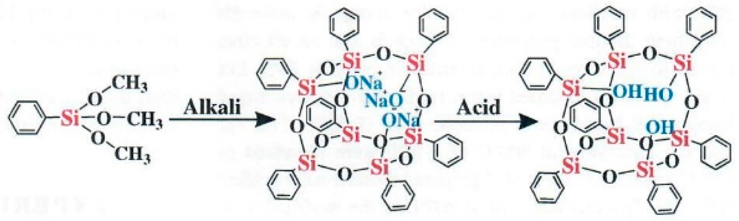
Figure 2.
Synthesis and curing process of POSSBPR (Reprinted with permission from [4]. Copyright John Wiley & Sons).
Figure 2.
Synthesis and curing process of POSSBPR (Reprinted with permission from [4]. Copyright John Wiley & Sons).
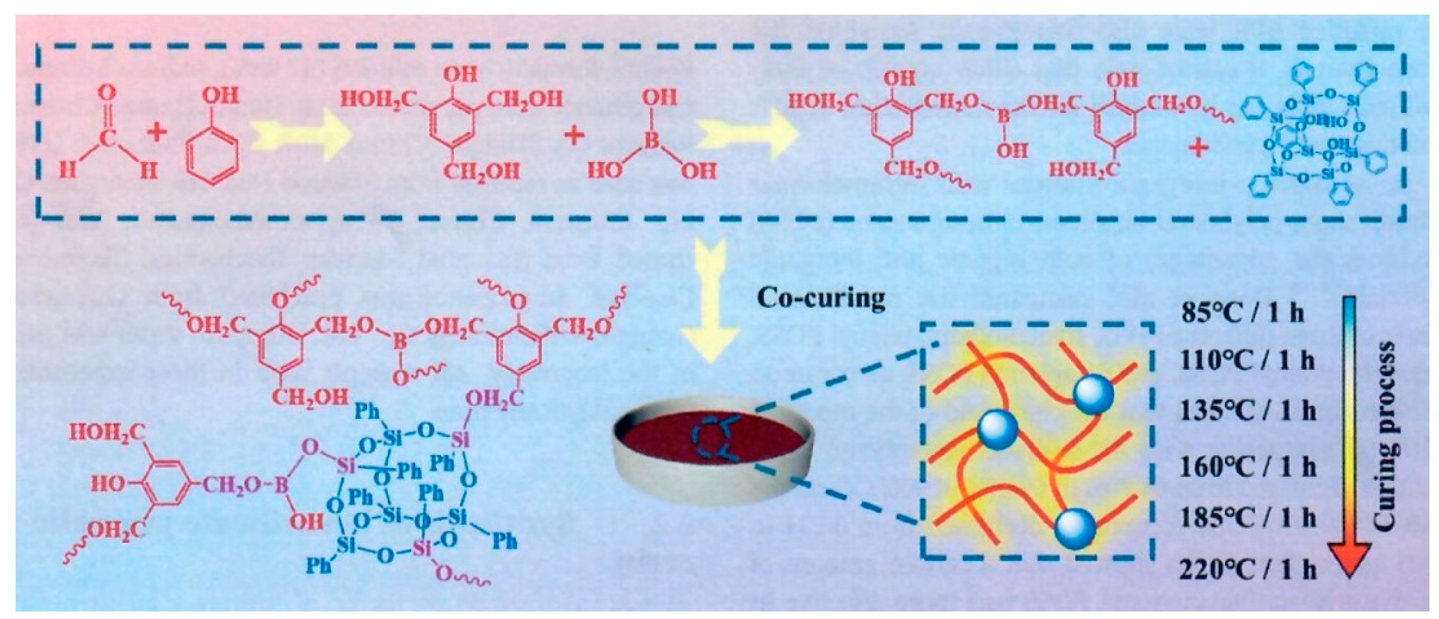
Figure 3.
Preparation process of composites (Reprinted from [5]. Copyright by the authors).
Figure 3.
Preparation process of composites (Reprinted from [5]. Copyright by the authors).
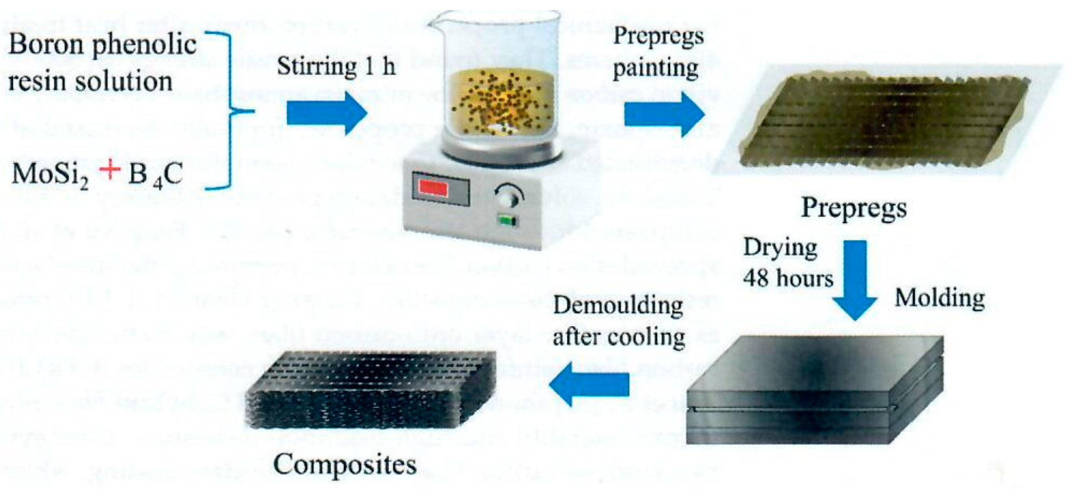
Figure 4.
TGA of insulation materials (Reprinted with permission from [7]. Copyright Elsevier).
Figure 4.
TGA of insulation materials (Reprinted with permission from [7]. Copyright Elsevier).
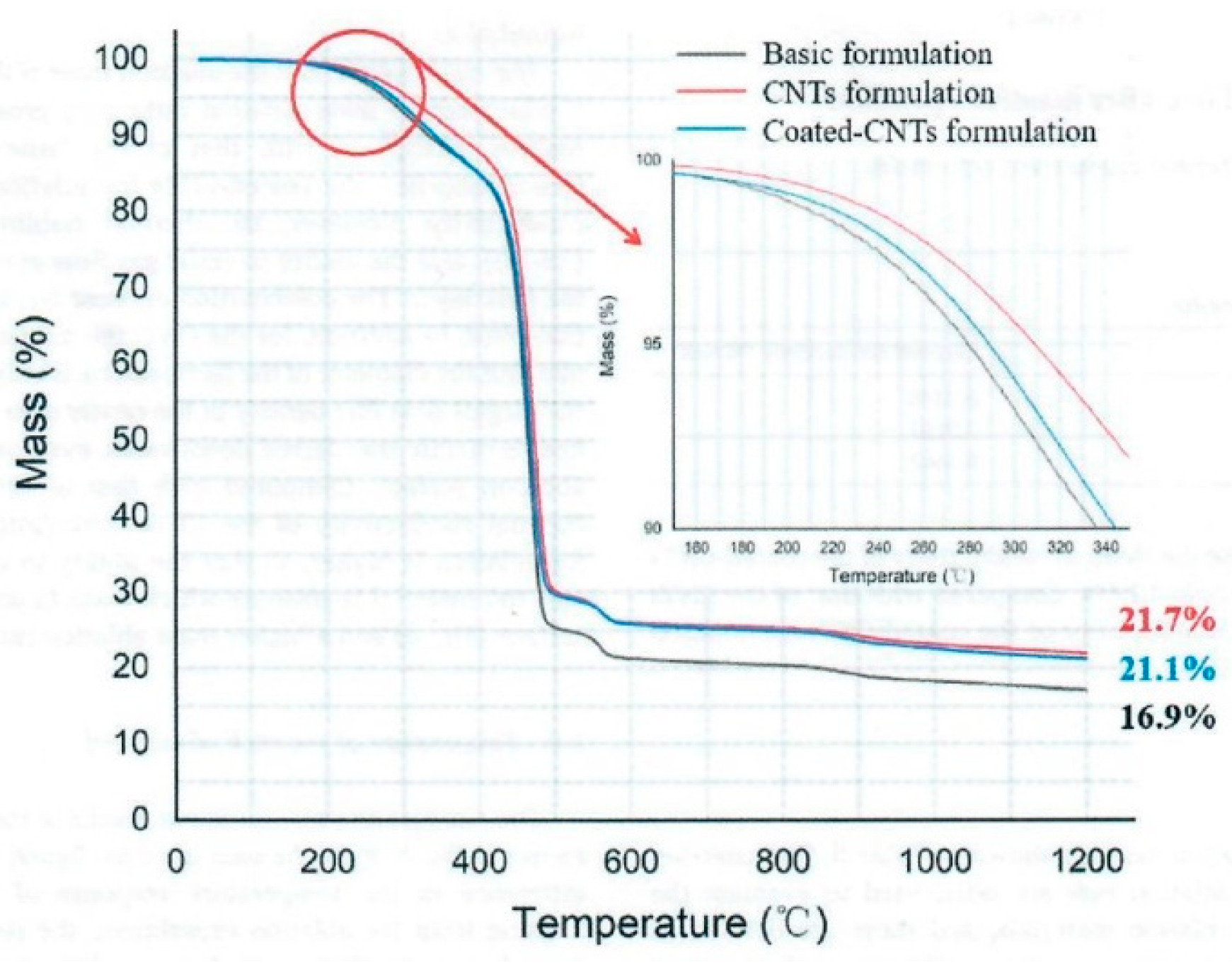
Figure 5.
Techneglas UHTR structure, properties, and comparison with high performance resins (Reprinted with permission from J. Buffy).
Figure 5.
Techneglas UHTR structure, properties, and comparison with high performance resins (Reprinted with permission from J. Buffy).
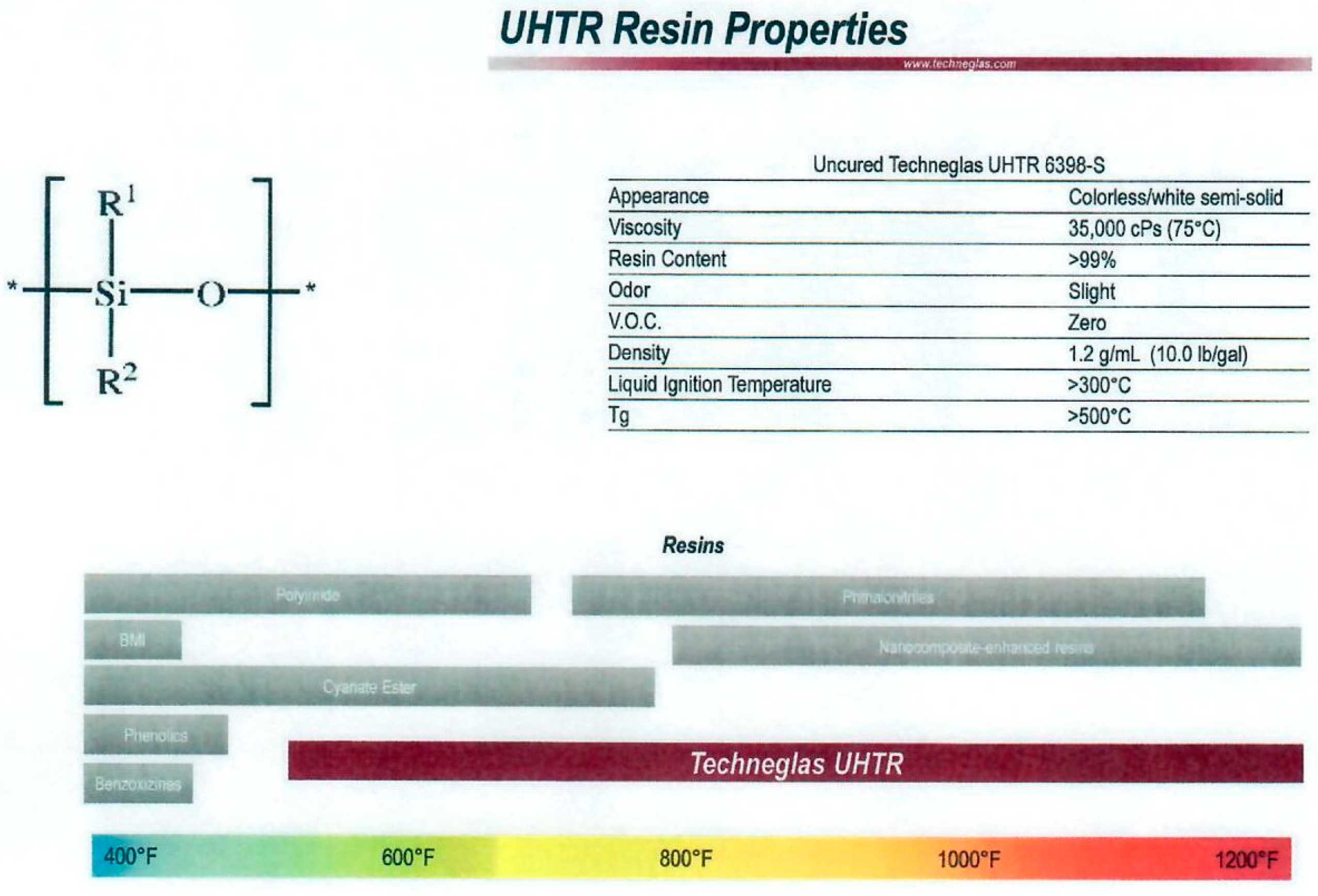
Figure 6.
TGA results of CF/UHTR MC and MX-4926 MC in air and nitrogen (Reprinted from [12]. Copyright by the authors).
Figure 6.
TGA results of CF/UHTR MC and MX-4926 MC in air and nitrogen (Reprinted from [12]. Copyright by the authors).
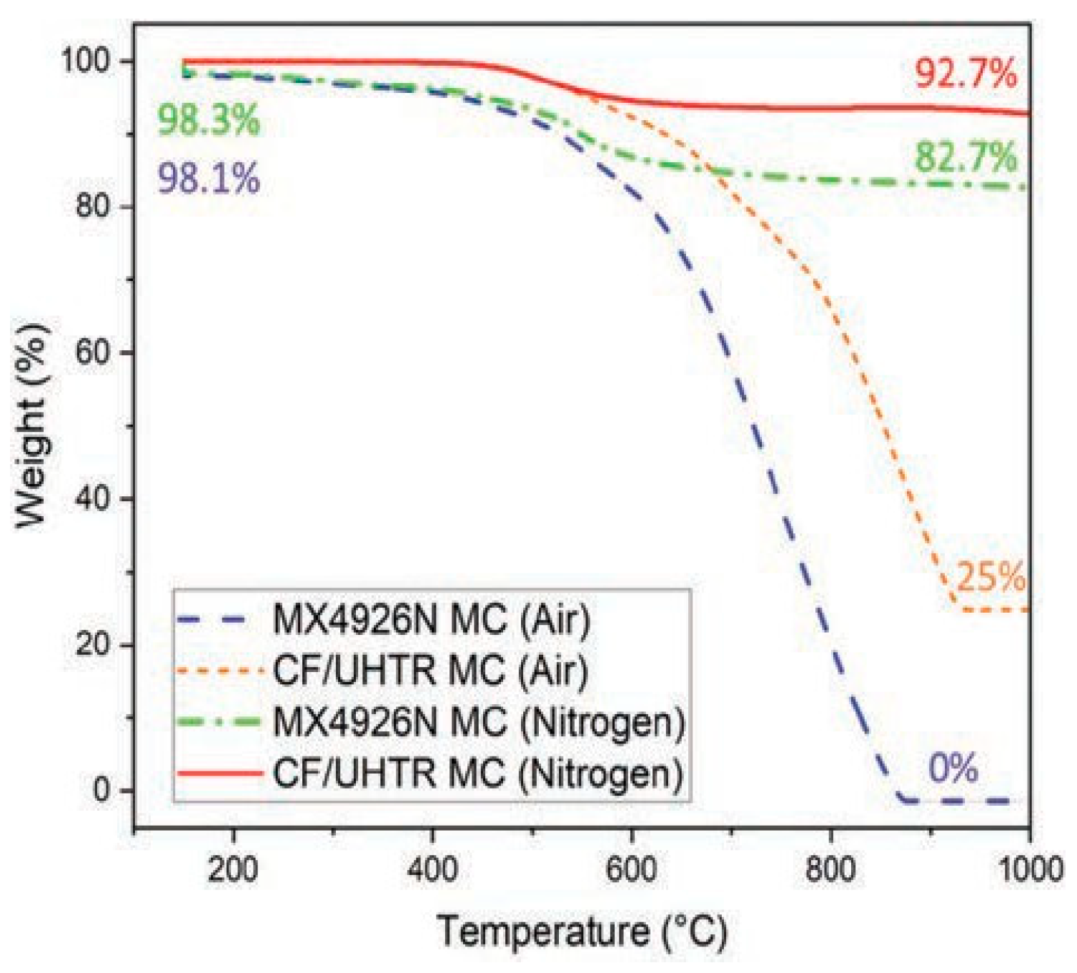
Figure 7.
CF/UHTR prepreg cut into (a) 0.5-inch (1.27-cm) width strips; (b) 0.5- by 0.5- inch (1.27- by 1.27-cm) squares; (c) CF/UHTR MC sample (3 inches (7.62 cm) in diameter and 0.5 inch (1.27 cm) in thickness) (Reprinted from [12]. Copyright by the authors).
Figure 7.
CF/UHTR prepreg cut into (a) 0.5-inch (1.27-cm) width strips; (b) 0.5- by 0.5- inch (1.27- by 1.27-cm) squares; (c) CF/UHTR MC sample (3 inches (7.62 cm) in diameter and 0.5 inch (1.27 cm) in thickness) (Reprinted from [12]. Copyright by the authors).
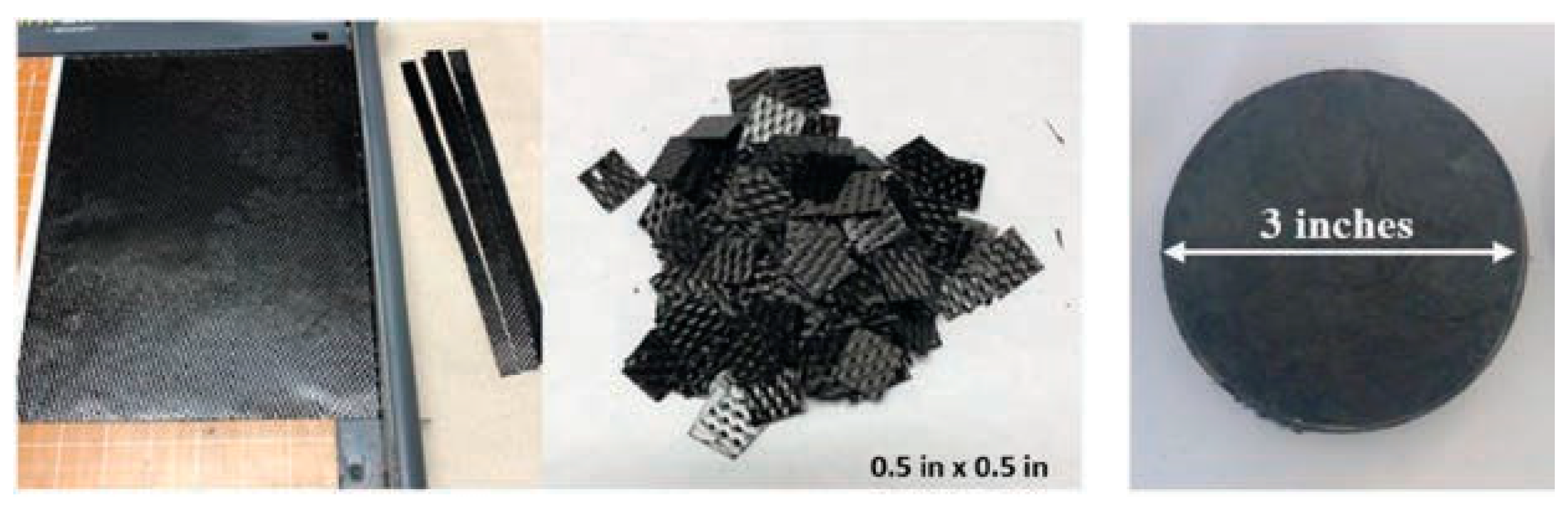
Figure 8.
Recession and mass loss results of MX-4926N and CF/UHTR composites (Reprinted from [13]. Copyright by the author).
Figure 8.
Recession and mass loss results of MX-4926N and CF/UHTR composites (Reprinted from [13]. Copyright by the author).
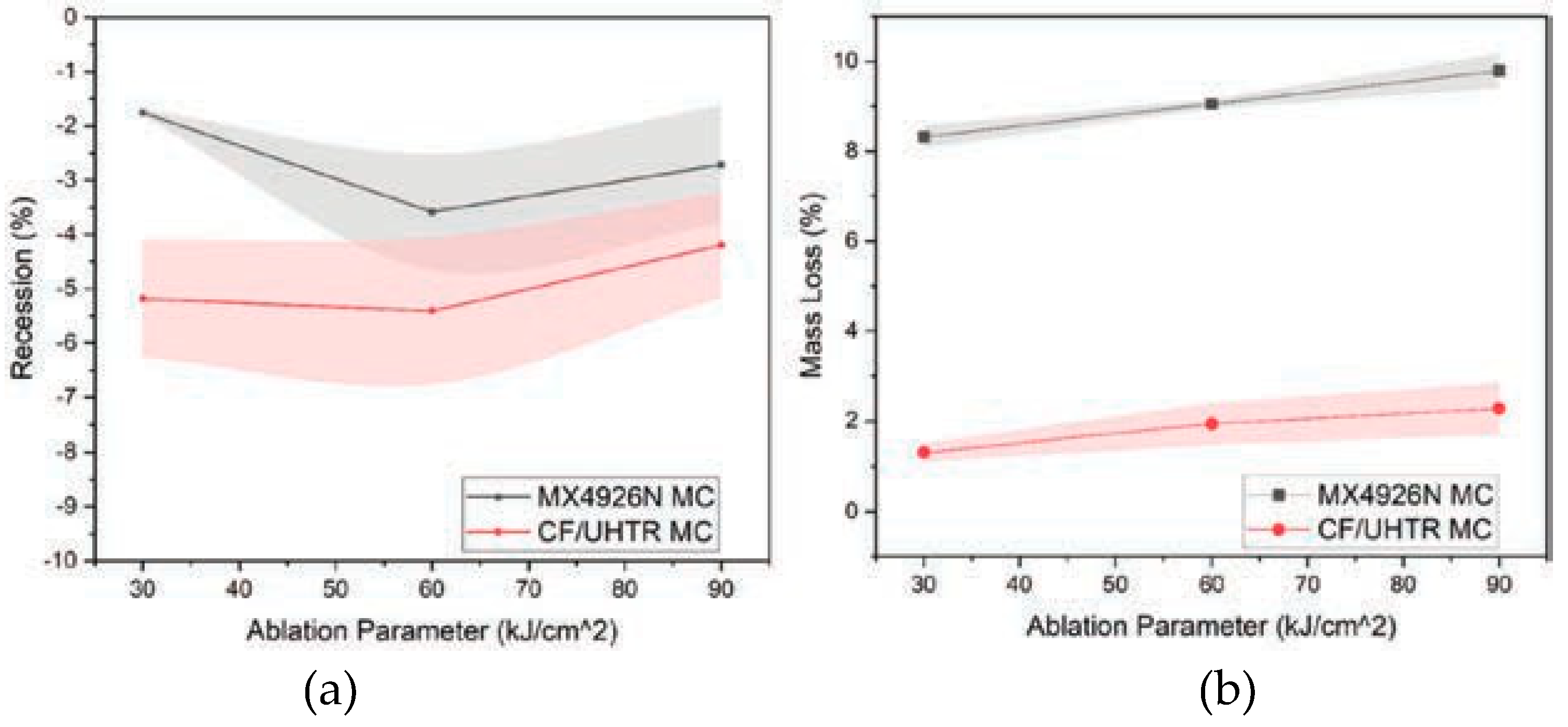
Figure 9.
Peak surface and peak heat-soaked temperatures of MX-4926N and CF/ UHTR from OTB testing (Reprinted from [13]. Copyright by the author).
Figure 9.
Peak surface and peak heat-soaked temperatures of MX-4926N and CF/ UHTR from OTB testing (Reprinted from [13]. Copyright by the author).
Figure 10.
(Left) Before and (Center) 30 seconds during and (Right) and temperature profiles of OTB testing of AP/UBC Sample 4 (Reprinted from [14]. Copyright by the author).
Figure 10.
(Left) Before and (Center) 30 seconds during and (Right) and temperature profiles of OTB testing of AP/UBC Sample 4 (Reprinted from [14]. Copyright by the author).
Figure 11.
Micro-CT slice in the YZ plane of (Left) virgin AP/UBC and (Right) annealed AP/UBC showing SiBOC formation. AP fibers are 5 μm wide for scale (Reprinted from [14]. Copyright by the author).
Figure 11.
Micro-CT slice in the YZ plane of (Left) virgin AP/UBC and (Right) annealed AP/UBC showing SiBOC formation. AP fibers are 5 μm wide for scale (Reprinted from [14]. Copyright by the author).
Figure 12.
Graphical timeline of decomposition of AP/U and AP/UBC with pyrolysis gases noted at the bottom (Reprinted from [14]. Copyright by the author).
Figure 12.
Graphical timeline of decomposition of AP/U and AP/UBC with pyrolysis gases noted at the bottom (Reprinted from [14]. Copyright by the author).
Figure 13.
Manufacturing procedure of CF/PN composite laminate specimen and one-sided butane flame heating test bench (a) Chemical structure of phthalonitrile resin; (b) Hot-pressing curve; (c) Specimen lay-up ([±45°/0°/90°]2s); (d) Specimen dimensions (30 x 30 x 2.735 mm3); and (e) Butane flame heating test bench (Reprinted with permission from [22]. Copyright Elsevier).
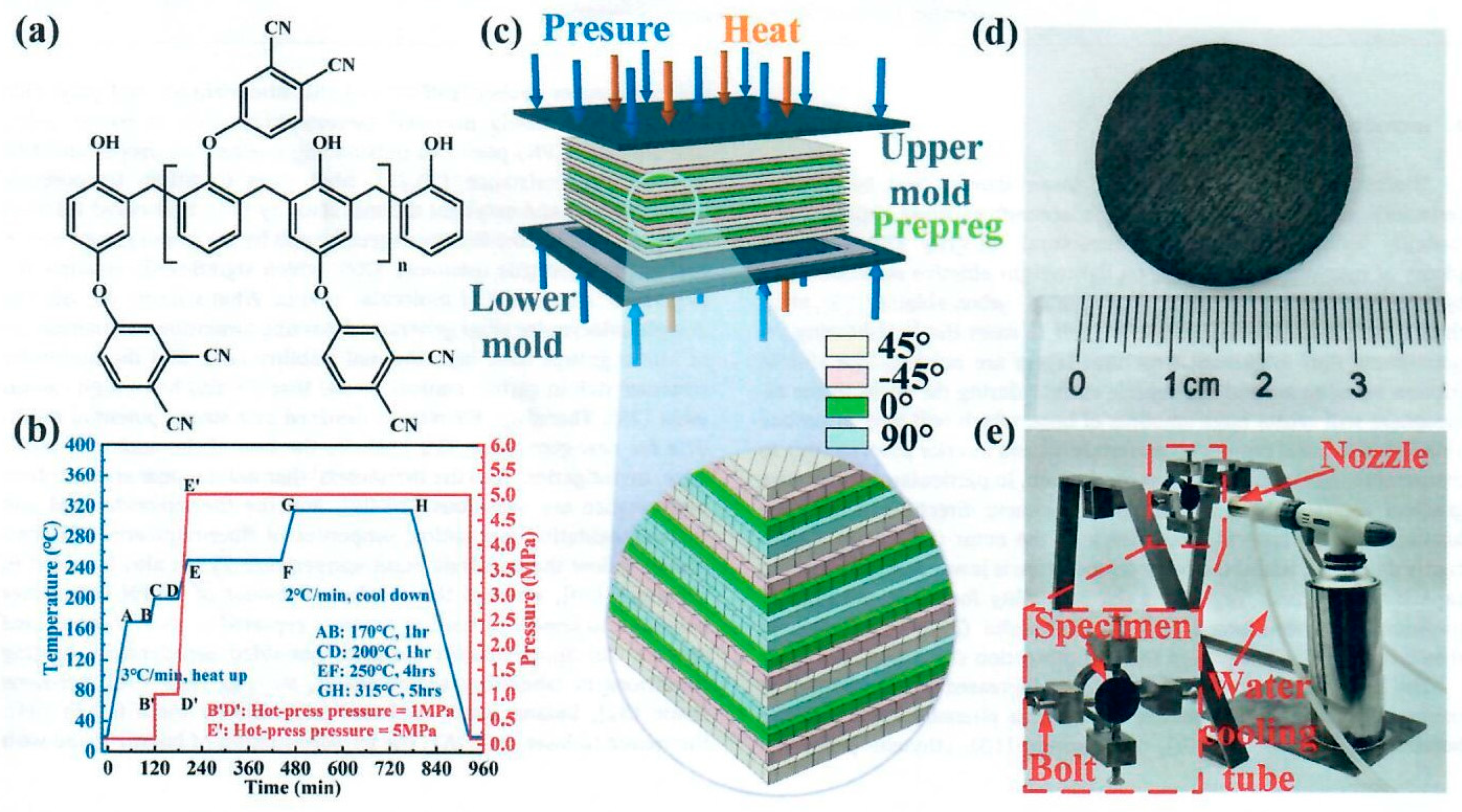
Figure 14.
a) Process for NCF-PR aerogel composite. 1. NCF, needle carbon fiber, 2. Vacuum immersion of NCF into PR/HMTA/EG. 3. Gelation and polymerization. 4. NCF-PR aerogel composite after curing. b and c) SEM image of NCF-PR aerogel composite in xy and z directions. d and e) High magnification of composite. Inset: Higher magnification image of PR aerogels in the space void and on the surface of the fibers (Reprinted with permission from [26]. Copyright Elsevier).
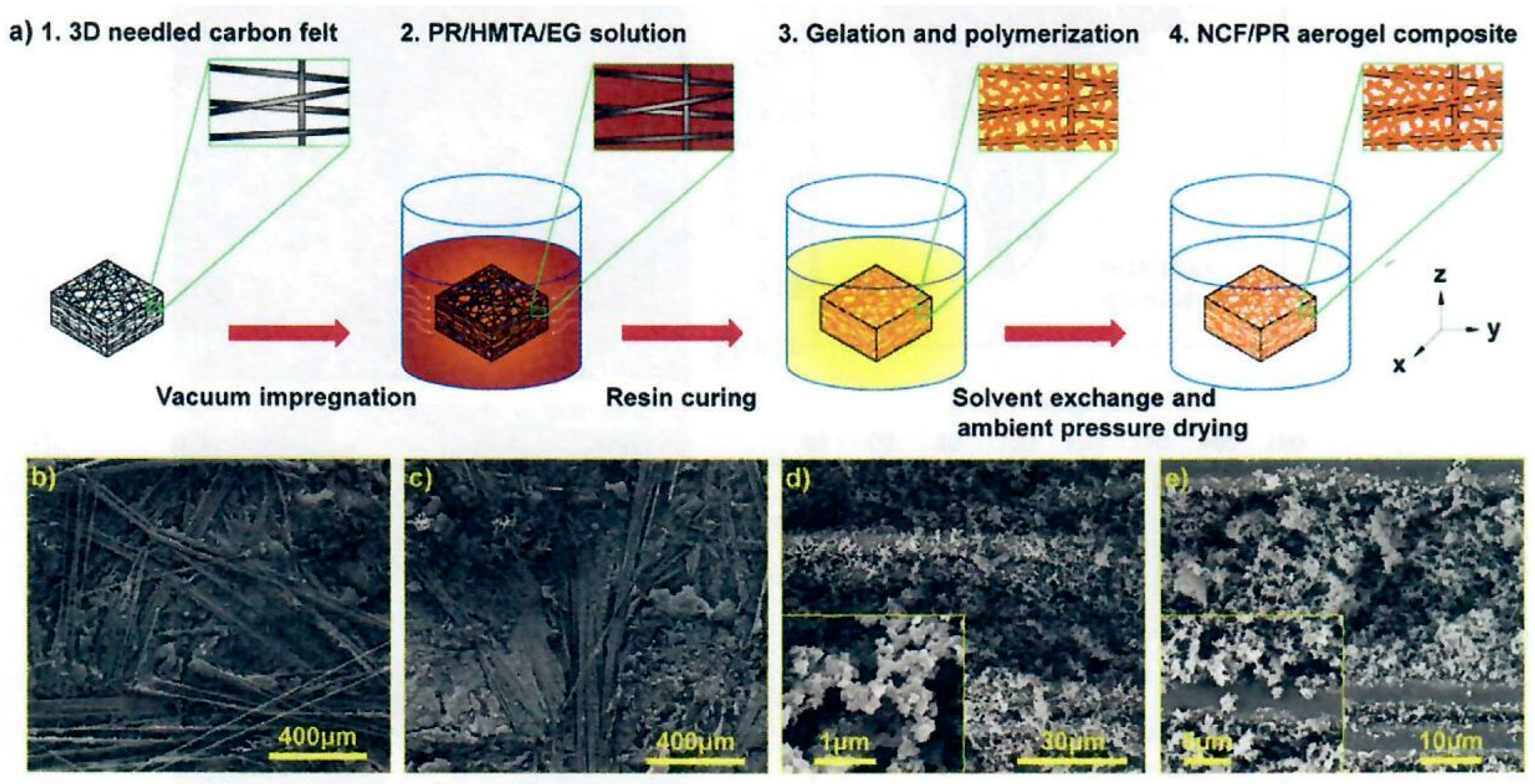
Figure 15.
a) Processing steps for near net-shape samples of HARLEM. b) Frontal view of a HARLEM sample with density of 0.27 g/cc. Optical microscopy image featuring the resin-containing phase within the carbon fibers (inset) (Reprinted from [28]. Copyright by the authors).
Figure 15.
a) Processing steps for near net-shape samples of HARLEM. b) Frontal view of a HARLEM sample with density of 0.27 g/cc. Optical microscopy image featuring the resin-containing phase within the carbon fibers (inset) (Reprinted from [28]. Copyright by the authors).
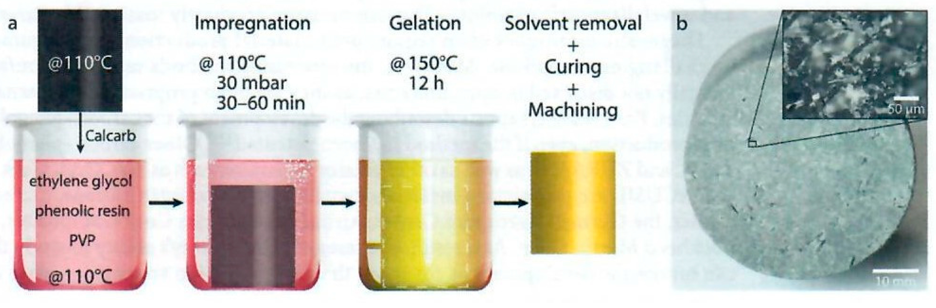
Figure 16.
Electron Microscopy images of the carbon-phenolic ablators (a) HARLEM, (b) ASTERM, and (c) PICA. Scale bars: 50 µm (Reprinted from [28]. Copyright by the authors).
Figure 16.
Electron Microscopy images of the carbon-phenolic ablators (a) HARLEM, (b) ASTERM, and (c) PICA. Scale bars: 50 µm (Reprinted from [28]. Copyright by the authors).
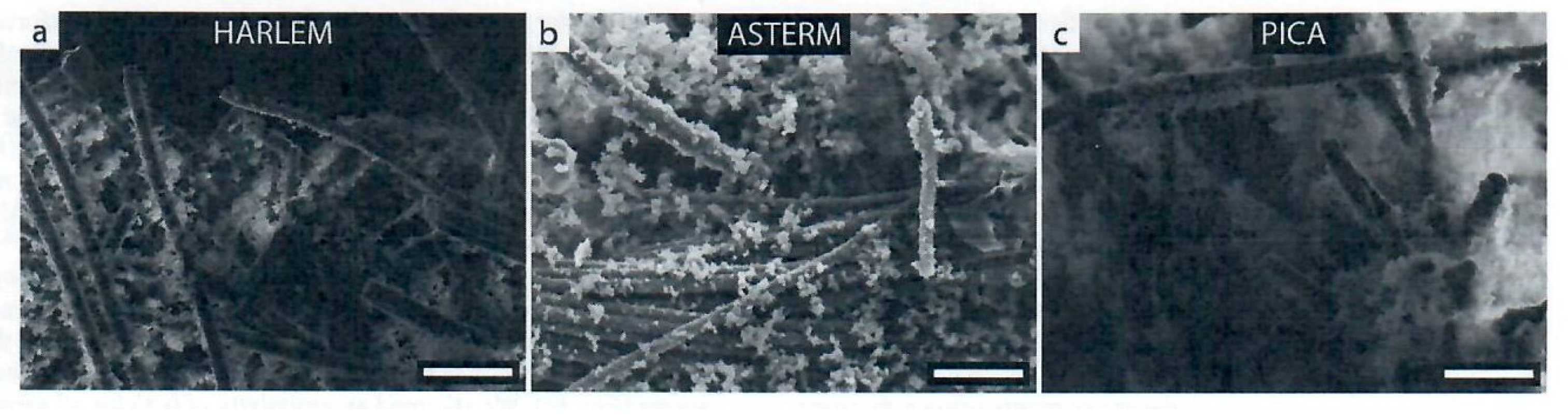
Figure 17.
Preparation process, macro- and microscopic structure of the C-QF/PSi aerogel nanocomposite. (a) Schematic diagram of the prepared process for C-QF/PSi aerogel nanocomposite. Step 1: Schematic of C-QF hybrid fabric produced by a needle-punching technique. Step 2: Vacuum impregnation of co-precursor solution into C-QF hybrid fabric. Step 3: Gelation and polymerization in PR/HMTA/EG solution. Step 4: Aerogel nanocomposite after curing, EtOH exchange and ambient pressure drying. (b) and (c) Representative fracture surface morphology at carbon fiber and quartz layer in xy direction, respectively. (d) SEM image of needling quartz fibers perpendicular to the laminated fibers. (e) High magnification SEM image of composite. Inset: higher magnification image of PSi hybrid aerogels in the space void between fibers and on the surface of fibers (Reprinted with permission from [29]. Copyright Elsevier).
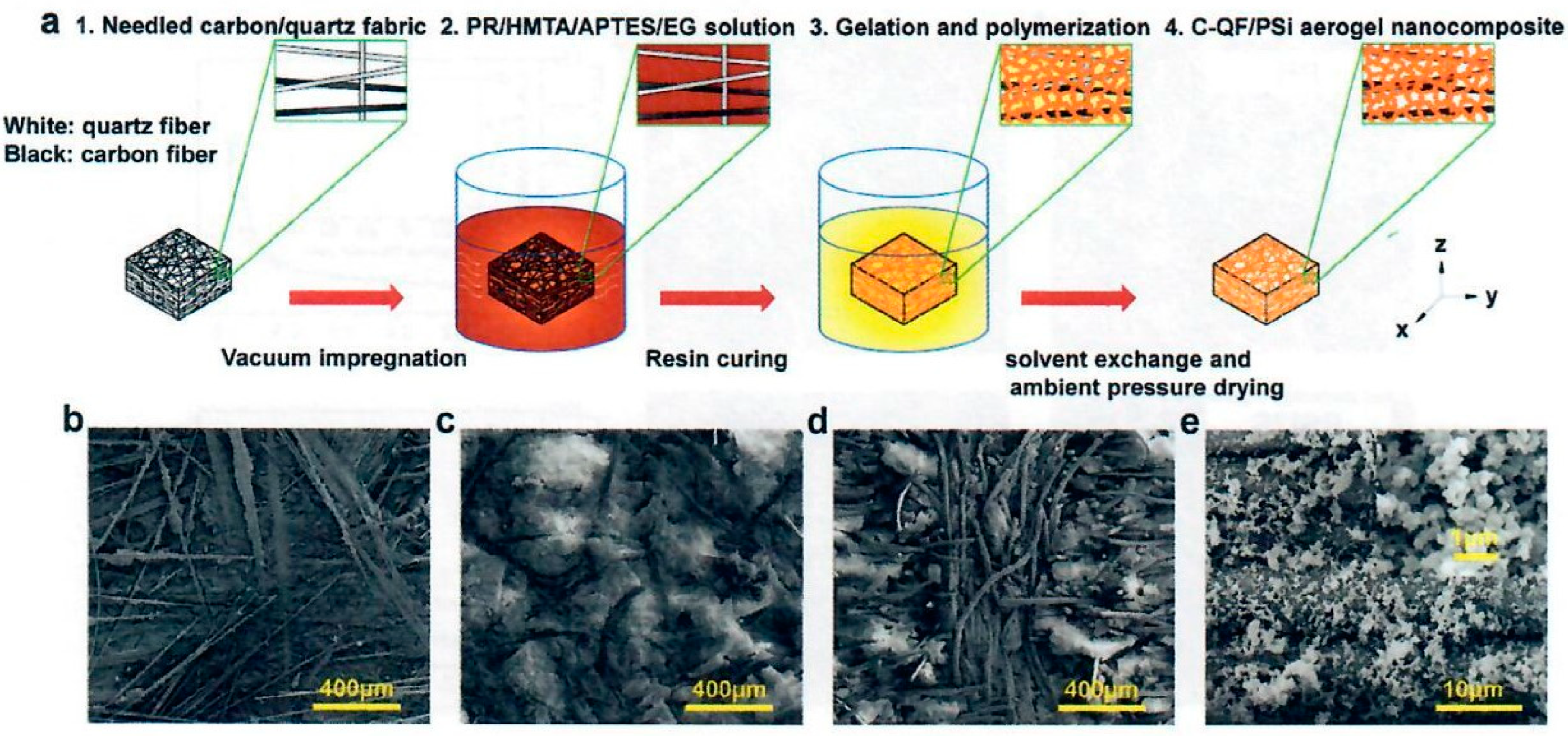
Figure 18.
Fabrication method and multiscale structure of SiCF/PR. (a) - (c) Schematic diagrams of NCF, SiCF, and SiCF/PR. (d) Chemical combination of SiOC and PR. (e) Macro photograph of SiCF/PR-4. (f) - (g) SEM images of SiCF/PR-4 at different magnifications (Reprinted with permission from [30]. Copyright Elsevier).
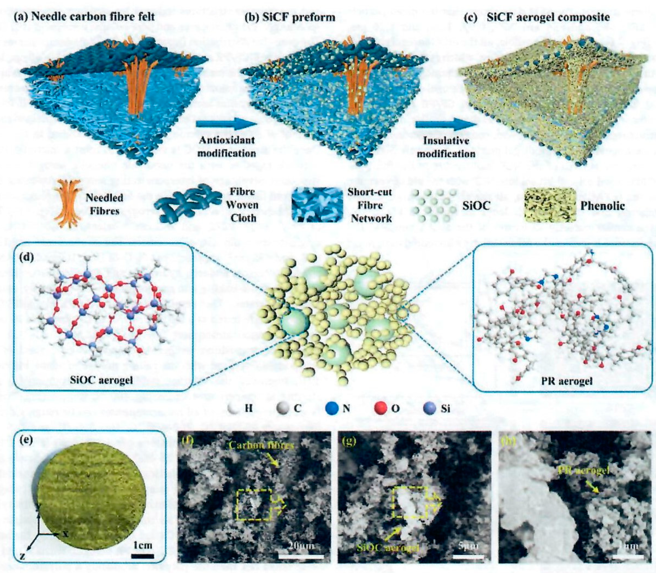
Figure 19.
The preparation process for NQF/CR/PR composite. (a) Diagrammatic process of surface densified and graded composite. (b) SEM image of needle quartz fiber felt. (c) Microstructure of dense surface layer. (d) Microstructure of internal layer. (e) Microstructure of phenolic aerogel (Reprinted with permission from [32]. Copyright Elsevier).
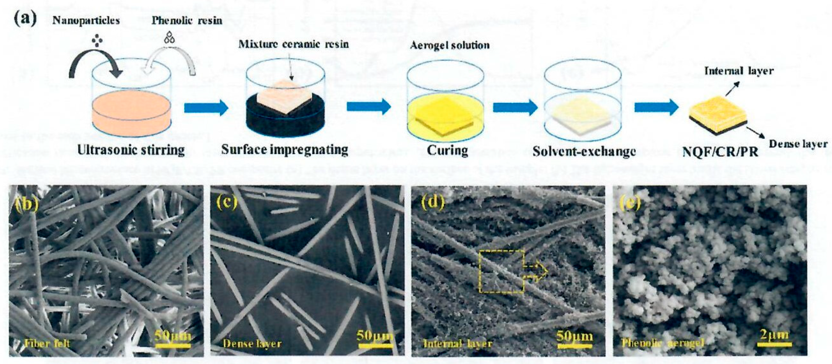
Figure 20.
Preparation process and microscopic structure correspond to each step. Schematic diagram of (a) CF, (b) TiCF, and (c) TiCF/PR. Chemical structures of (d) CF, (e) anatase TiO2, and (f) PR aerogel. SEM image of (g) unglued CF, (h) TiCF, (i) TiCF/PR, and (j) macro photograph of TiCF/PR (Reprinted with permission from [35]. Copyright Elsevier).
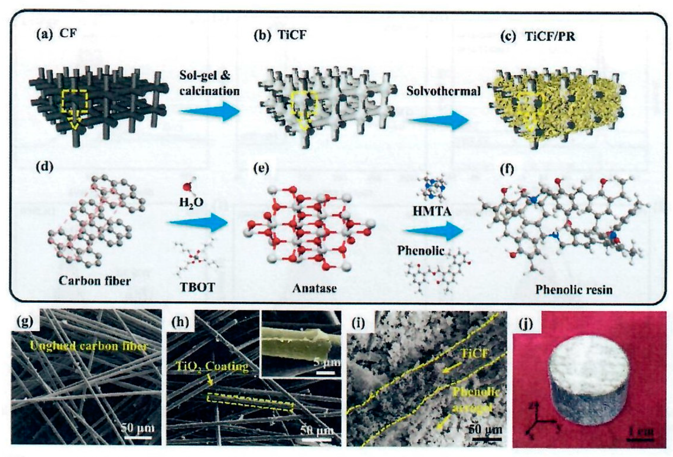
Figure 21.
Microscopic morphology of (a) TiCF/PR and (b) TiCF, (c) morphology of TiO2 with high magnification. (d) Interface between TiO2 and PR aerogel, with inset of EDS of Figure 21 (d). (e) SEM image of PR aerogel. (f) High magnification morphology of PR aerogel (Reprinted with permission from [35]. Copyright Elsevier).
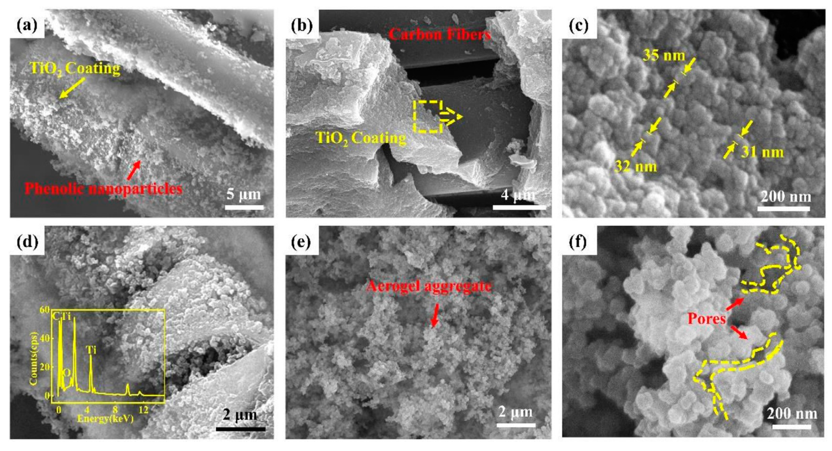
Figure 22.
Manufacturing process and macro-microstructure of Cf/TS and Cf/TS-PR; (d) – (e) Synthesis reactions of TS and PR; (f) Macro digital photograph of CP – 0.25-400; (g) – (h) SEM images of Cf/TS and Cf/TS-PR (Reprinted with permission from [34]. Copyright Elsevier).
Figure 22.
Manufacturing process and macro-microstructure of Cf/TS and Cf/TS-PR; (d) – (e) Synthesis reactions of TS and PR; (f) Macro digital photograph of CP – 0.25-400; (g) – (h) SEM images of Cf/TS and Cf/TS-PR (Reprinted with permission from [34]. Copyright Elsevier).
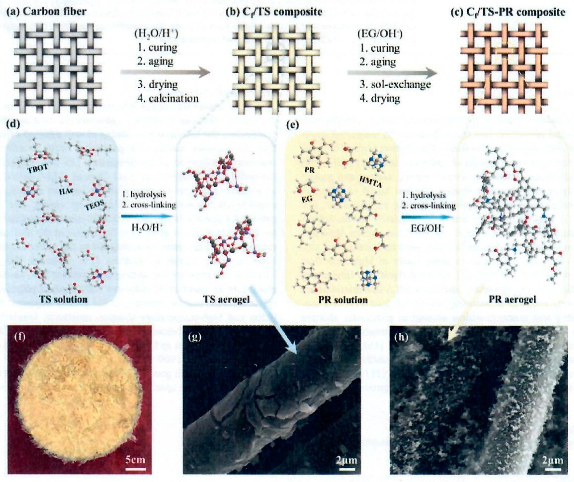
Figure 23.
Scheme of the synthesis and molecular structure of PRAWs (Reprinted with permission from [38]. Copyright Elsevier).
Figure 23.
Scheme of the synthesis and molecular structure of PRAWs (Reprinted with permission from [38]. Copyright Elsevier).
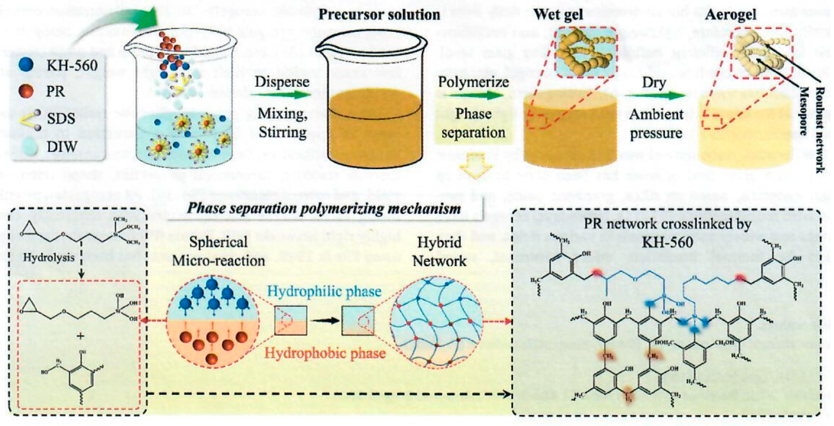
Figure 24.
Preparation of C/C composites through impregnation, high pressure-assisted polymerization, ambient pressure drying, and carbonization. The insets (a) and (b) are typical 3D XRT images of PF felt (Reprinted with permission from [41]. Copyright 2022 American Chemical Society).
Figure 24.
Preparation of C/C composites through impregnation, high pressure-assisted polymerization, ambient pressure drying, and carbonization. The insets (a) and (b) are typical 3D XRT images of PF felt (Reprinted with permission from [41]. Copyright 2022 American Chemical Society).
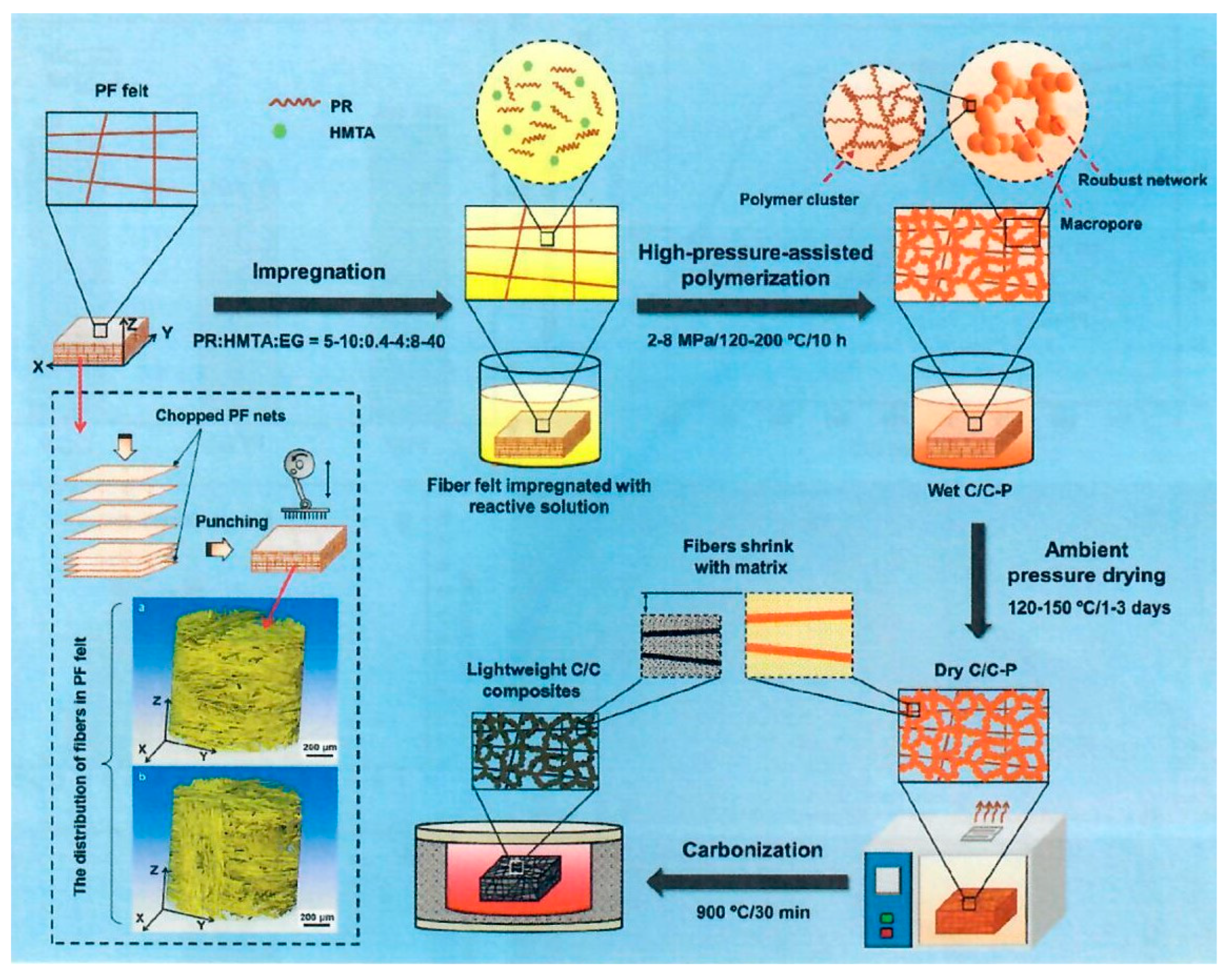
Figure 25.
Schematic illustration of the synthesis and structural composition of PRF/SiO2 composite aerogel with interpenetrating binary network (Reprinted with permission from [43]. Copyright John Wiley & Sons).
Figure 25.
Schematic illustration of the synthesis and structural composition of PRF/SiO2 composite aerogel with interpenetrating binary network (Reprinted with permission from [43]. Copyright John Wiley & Sons).
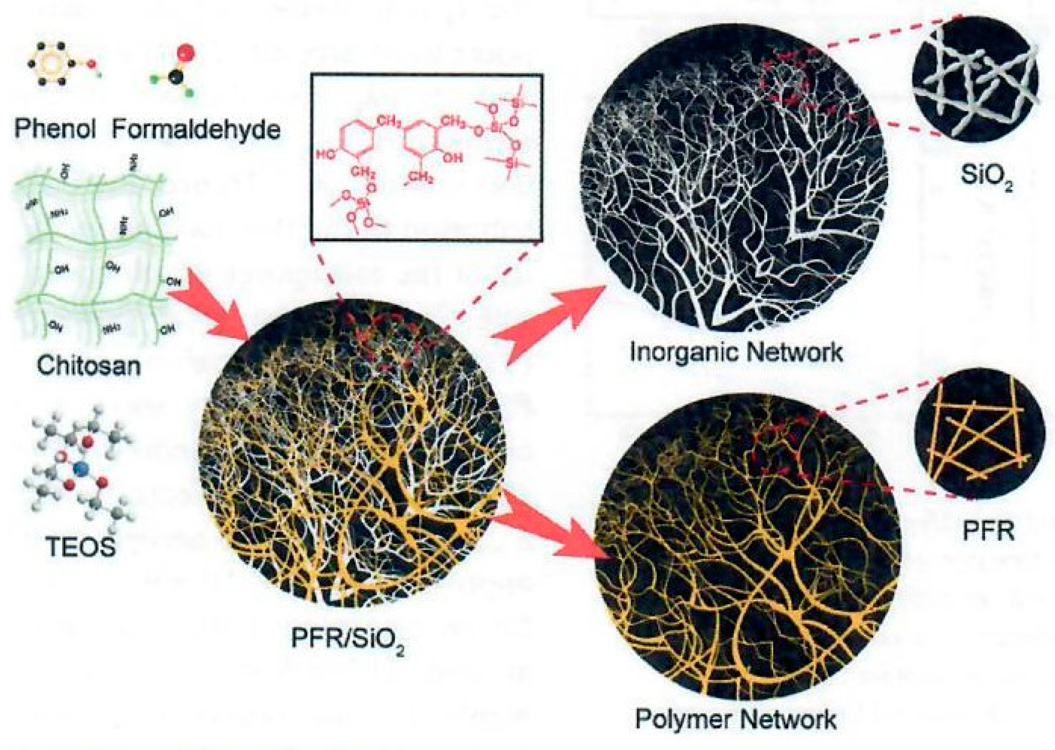

Table 1.
Diameter changes of carbon fibers treated at different temperatures (Data from [5]).
Table 1.
Diameter changes of carbon fibers treated at different temperatures (Data from [5]).
| Treatment Temperature |
/µm | ||
|---|---|---|---|
| Carbon Fibers | BP-0 | BP-15 | |
| RT | 7.118 | 7.118 | 7.118 |
| 800℃ | 6.034 | 6.178 | 6.892 |
| 1000℃ | 5.393 | 5.487 | 6.296 |
| 1200℃ | 4.999 | 5.097 | 5.592 |
| 1400℃ | 4.863 | 6.042 | 6.681 |
Table 2.
Parameters of CNTs with different sizes (Data from [8]).
Table 2.
Parameters of CNTs with different sizes (Data from [8]).
| Product number | Inner diameter (nm) | Outer diameter (nm) | Length (µm) | |
|---|---|---|---|---|
| Conventional CNTs | CNTs-010-0 | 3-5 | 8-15 | 3-12 |
| Long CNTs | CNTs-010 | 3-5 | 8-15 | 30-50 |
| Short CNTs | CNTs-007-1 | 3-5 | 8-15 | 0.5-2 |
| Large diameter CNTs | CNTs-014 | 5-15 | >50 | 10-15 |
Table 3.
OTB test conditions (Data from [13]).
Table 3.
OTB test conditions (Data from [13]).
| Simulated Reentry Conditions | ||
|---|---|---|
| Heat flux (W/cm2) | Exposure time (s) | Ablation parameter (kJ/cm2) |
| 500 | 60 | 30 |
| 1,000 | 60 | 60 |
| 1,500 | 60 | 90 |
Table 4.
Averages and standard deviations of all 30 second A/U tests (Data from [14]).
Table 4.
Averages and standard deviations of all 30 second A/U tests (Data from [14]).
| Sample Type | Cold Wall Heat Flux | Time | Recession | Mass Loss | Peak Surface Temperature | Peak Back Face Heat Soak Temperature | Time to Peak Back Face Heat Soak |
| W/cm2 | s | mm | g | °C | °C | s | |
| AF/U | 1,000 | 30 | 2.55 ± 0.87 | 1.05 ± 0.52 | 2181 ± 20 | 149 ± 13 | 200 ± 6 |
| AF/UBC | 1,000 | 30 | 2.68 ± 0.78 | 0.57 ± 0.16 | 2162 ± 15 | 166 ± 26 | 199 ± 11 |
| AP/U | 1,000 | 30 | 1.98 ± 0.13 | 0.58 ± 0.25 | 2093 ± 28 | 139 ± 18 | 241 ± 3 |
| AP/UBC | 1,000 | 30 | 0.98 ± 0.24 | 0.72 ± 0.06 | 2118 ± 7 | 165 ± 6 | 220 ± 15 |
| AP/UBC | 500 | 30 | -0.03 ± 0.11 | 0.40 ± 0.14 | 1779 ± 56 | 146 ± 13 | 213 ± 11 |
Table 5.
Weight ratio of ceramic particles to PR (Data from [34]).
Table 5.
Weight ratio of ceramic particles to PR (Data from [34]).
| QFPSx | Used Ceramic Resin | |||
| CRx | ZrB2 | SiC | PR | |
| QFPS1 | CR1 | 10 | 0 | 10 |
| QFPS2 | CR2 | 10 | 10 | 20 |
| QFPS3 | CR3 | 10 | 2 | 12 |
Table 6.
Summary of C/C composites properties before and after heating tests (Data from [41].
Table 6.
Summary of C/C composites properties before and after heating tests (Data from [41].
| No. | Properties | Before | After |
|---|---|---|---|
| 1 | Bulk density (g cm-3) | 0.60 | 0.58 |
| 2 | Compressive strength (MPa) | 80 ± 3 | 96 ± 5 |
| 3 | Compressive modulus (MPa) | 1557 ± 86 | 1707 ± 92 |
| 4 | Specific strength (MPa g-1 cm-3) | 133 | 155 |
| 5 | Thermal conductivity (W m-1 K-1) | 0.32 | 0.42 |
| 6 | Interlaminar shear strength (MPa) | 15 ± 2 | 17 ± 3 |
| 7 | In-plane shear strength (MPa) | 20 ± 4 | 23 ± 5 |
Table 7.
Ablation characteristics summary of ablative composites in this review.
| Ablative Composites | Linear Ablation Rate (LAR) [mm/s] or [%] | Mass Ablation Rate (MAR) [g/s] or [%] | Method of Ablation Test | References |
|---|---|---|---|---|
| Boron modified phenolic resin (PR) with heptaphenyl POSS impregnation of silica fiber (POSSBPR4/silica fiber) | 0.123 mm/s | 0.0602 g/s | Oxy-acetylene test bed (OTB) at 418.68 W/cm2 for 20 s | Niu et al. [4] |
| Constant amount of MoSi2 to boron phenolic resin and varied B4C into boron modified phenolic resin impregnation of carbon fiber fabric | 0.013 mm/s (20% B4C) | 0.0815 g/s (15% B4C) | Unknown OTB test conditions | Yang et al. [5] |
| Z-pinning effect on interlaminar mechanical and ablation performance of quartz fiber/phenolic composites | No data | No data | Ablation in a flame of 920°C for 60 s of unknown heat flux | Li et al. [6] |
| Polysiloxane resin impregnation of carbon fabric | -5.8, -5.7, -4.1% for 500, 1,000, and 1,500 W/cm2, respectively | 1.1, 1.5, and 2% mass loss for 500, 1,000, and 1,500 W/cm2, respectively | OTB at 500, 1,000, and 1,500 W/cm2 for 60 s | Hou et al. [12] |
| Polysiloxane resin impregnation of alumina fabrics | -0.001 to 0.089 mm/s | 0.013 to 0.035 g/s | OTB at 500 and 1,000 W/cm2 for 30 s | Yee [14] |
| Phthalonitrile (PN) resin impregnation of carbon fiber (CF/PN) | No data | No data | Butane flame method | Yang et al. [22] |
| Phenolic novolac phthalonitrile (NPN) blends with novolac cyanate ester (NCE) impregnation of carbon fiber | Heat of ablation (8.000–12,000 cal/g) | 4.77–5.77% | Radiant heating conditions (~55 W/cm2 for 1,200 s) and plasma Arc jet (70 and 125 W/cm2 for 50 s) | Sreelal et al. [23] |
| Needle carbon fiber (NCF) felt in phenolic aerogel composite | 0.029 mm/s | No data | OTB at 115 W/cm2 for 33 s | Cheng et al. [26] |
| Low-density (0.27 g/cc) HARLEM using PIPS technology with PR/PVP/EG impregnation of carbon felt | 48 µm/s | No data | Arc jet testing at 540 W/cm2 for 30 s | Poloni et al. [27,28] |
| Low-density carbon fiber-quartz fiber needled felt (C-QF) reinforced by phenolic-silica (C-QF/PSi) aerogel nanocomposite | No data (improved ablation performance) | No data | Surface temperature >2,000°C using oxy-acetylene torch for 300 s, no heat flux measurement | Cheng et al. [29] |
| Needled CF felt (NCF) reinforced by SiOC using sol-gel method infiltrate with phenolic aerogel | 0.0282 to 0.0109 mm/s | 0.0186 to 0.0157 g/s | OTB at 150 W/cm2 for 300 s | Jin et al. [30] |
| Needled QF felt (NQF) reinforced by SiOC using sol-gel method on the felt infiltrate with phenolic aerogel (SiQF/PR) | 0.023 mm/s | No data | OTB at 180 W/cm2 for 120 s | Jin et al. [31] |
| Low-density (0.20 g/cc) treated needled quartz fiber felt (NQF) with 3 ceramic particles: ZrB2 (500-800 nm), SiO2 (20-50 nm), and glass in phenolic resin | 0.010 mm/s | 0.020 g/s | OTB at 150 W/cm2 for 90 s at a high temperature >1,700°C | Wang et al. [32,33] |
| Low-density (0.14 g/cc) ZrB2 (0.8-1 µm) and SiC (500-800 nm) in phenolic resin in impregnation of QF felt | 0.003 mm/s | 0.016 g/s | OTB testing 150 W/cm2 for 90 s | Wang et al. [34] |
| Low-density nano-TiO2 coated needled carbon fiber reinforced phenolic resin aerogel composite | 26.2 µm/s | 8.4 mg/s | OTB at 150 W/cm2 for 150 s | Pan et al. [35] |
| Low-density and low porosity (0.20 g/cc and 85%) TiO2 coated needled carbon fiber felt with phenolic aerogel composites through co-gelation (TiO2-SiO2) | 0.004 and 0.003 mm/s at 100 and 150 W/cm2 for 240 s, respectively | 0.006 and 0.009 g/s for 100 and 150 W/cm2 for 240 s, respectively | OTB at 100 and 150 W/cm2 for 240 s | Wang et al. [34] |
| Medium-density C/C composites (0.6 g/cc) using 3D chopped phenolic fiber felt with phenolic resin | 0.03 µm/s | 0.3% and 6.8% | Oxy-acetylene flame heating tests conducted at 1,800°C, for 900 s, no heat flux measurement | Li et al. [41] |
Disclaimer/Publisher’s Note: The statements, opinions and data contained in all publications are solely those of the individual author(s) and contributor(s) and not of MDPI and/or the editor(s). MDPI and/or the editor(s) disclaim responsibility for any injury to people or property resulting from any ideas, methods, instructions, or products referred to in the content. |
© 2024 by the authors. Licensee MDPI, Basel, Switzerland. This article is an open access article distributed under the terms and conditions of the Creative Commons Attribution (CC BY) license (http://creativecommons.org/licenses/by/4.0/).
Copyright: This open access article is published under a Creative Commons CC BY 4.0 license, which permit the free download, distribution, and reuse, provided that the author and preprint are cited in any reuse.


