1. Introduction
In machining, high temperature is one of the main factors of accelerated tool wear [
1,
2,
3].
The bibliography presents commercial and scientific descriptions of the use of cryogenic substance for cooling the workpiece during cavity cutting by various manufacturing techniques especially for alloys of hard-to-machine materials such as titanium Ti alloys, cobalt Co alloys, magnesium Mg alloys [
4,
5,
6,
7].
The results obtained focus on explaining the improvement of machining processes with special attention to the reduction of contamination generated by coolant and lubricating fluids. Consequently, many authors explain the relationship between cutting processes and minimum lubrication in the contact zone of the cutting edge and workpiece material, the use of cryogenic substances as coolant and biodegradable vegetable oils. The conclusions developed are to explain the effects of cutting forces, energy consumption, cutting temperatures, improving surface quality, and extending tool life [
8].
The use of new solutions in cooling the cutting zone is also related to ergonomics on the material parameters of the operator's working environment and his health, occupational diseases.
For this reason, methods of taking heat away from the cutting zone and environmental friendliness among alternative methods include cryogenic processing. It uses substances with negative temperatures such as dry ice (about -78 °C) and extremely low temperatures such as liquid oxygen (about -183 °C), liquid nitrogen (about -196 °C), liquid hydrogen (about -252.8 °C), liquid helium (-269 °C) [
9]. The use of cryogenic processing affects the total cost of manufactured machine and equipment parts by up to 30% [
10].
Publications on the measurement of cutting temperature do not fully clarify the correct value of this temperature. For example, the paper [
11] presents that the measured temperature values are in the range of 20 to 40 C as a function of the depth of cut ap. It is doubtful that such a value of cutting temperature was obtained because the method of measurement was not presented in the conceptual diagram or photograph, and the equipment used was not very precise.
Cooling rate, soaking period, temperature and tempering process are among the factors affecting the effectiveness of cryogenic treatments [
12].
In the work of [
13], an experiment was conducted to illustrate in an inverse FEM expression the rate of heat transfer from an Inconel 718 object. It was found that the surface heat coefficient is not constant and decreases with increasing temperature of liquid nitrogen due to convection and dissipation on the surface of the material. Heat by convection forms a thin layer on the surface of the object and "boiling bubbles," and this results in heat transfer with very low conductivity (about 0.03 W/m2K).
Meanwhile, the following works [
14,
15] take the surface heat transfer coefficient in the range of 23270 to 46750 W/m2K and 48270 to 74950 W/m2K as a constant value.
The main idea behind the use of the cryogenic cooling method is to change the physical properties of materials so that ductile materials at low temperature values become less ductile and behave like brittle materials. This property is expected to lead to better separation of the cutting material by the cutting edge [
16,
17].
2. Cryogenic Methods of Remote, Jet Cooling and Pre-Cooling the Workpiece
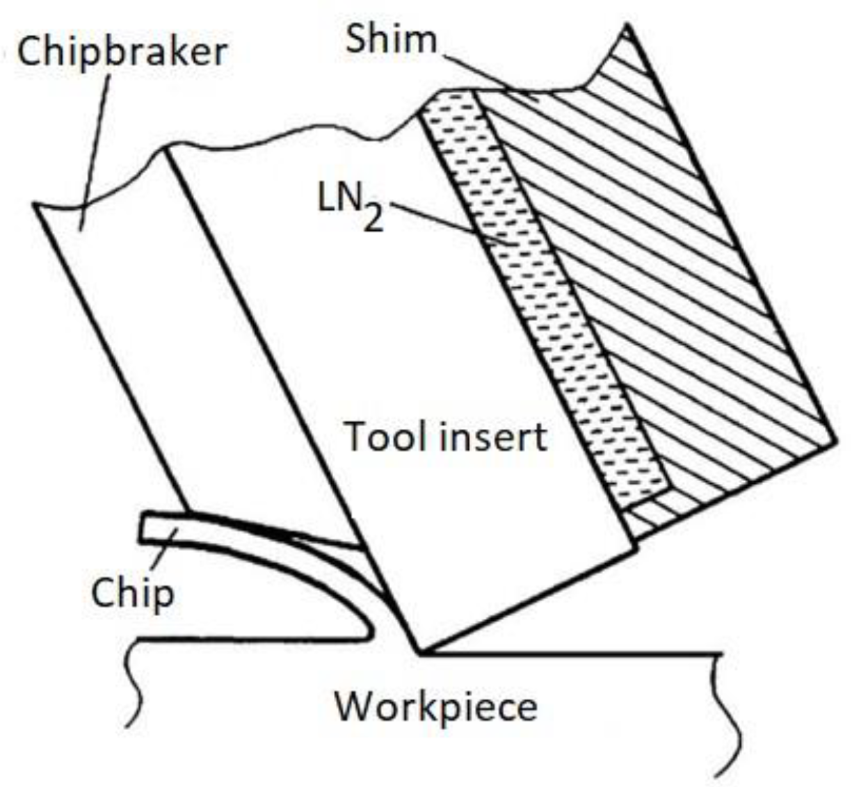
The main design solutions for supplying the cryogenic medium to the cutting zone consist of cooling the cutting tool through the cryogenic medium, which is supplied to a special chamber located under the insert (
Figure 1).
In this variation (
Figure 1), there is a limitation related to the thermal conductivity of the exchange plate material and its size, and liquid nitrogen is not in contact with the workpiece material, which may not significantly affect the changes in the workpiece material.
There are also methods of supplying the cryogenic medium to the cutting zone through special independent nozzles or micro-nozzles located directly in the tool (
Figure 2). This method works well for cooling with volatile liquid nitrogen compounds and partially covers the cutting zone, the tool and the resulting chip.
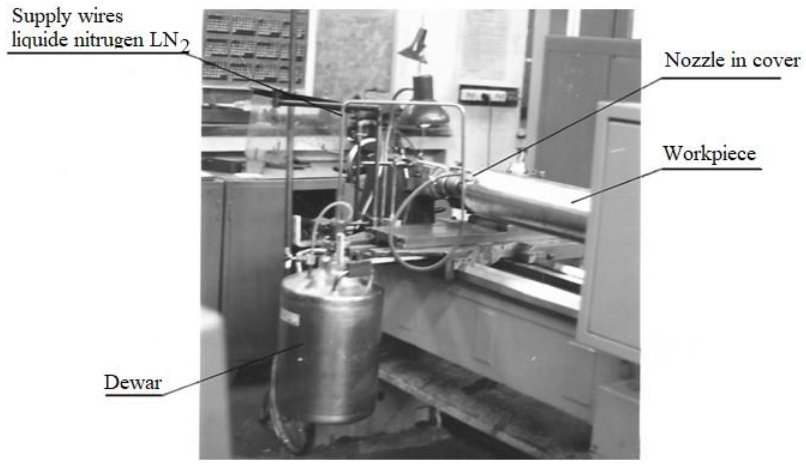
A test stand where liquid nitrogen was delivered from the dewar through special hoses to the machined surface is presented in
Figure 3. The design had its originality because a badger bristle guard was mounted at the end of the liquid nitrogen outlet nozzle to limit the splashing of the liquid jet. The nozzle had three 1.4 mm diameter holes in parallel, and the liquid jet was directed in front of the cutting edge during the turning process [
21].
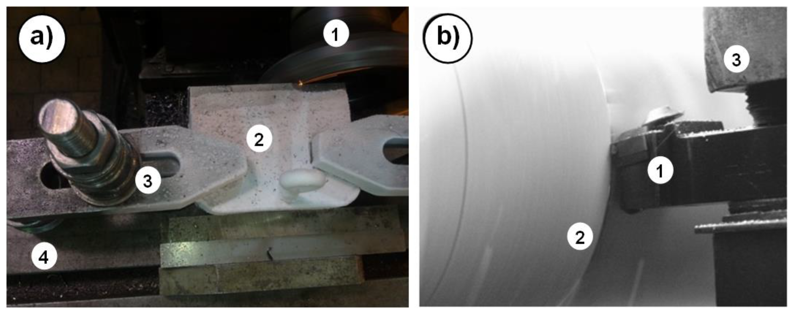
Another method of removing heat from the workpiece is temporary (the workpiece is bathed in liquid nitrogen before machining, or poured over it during machining-cryogenic pre-cooling the workpiece) or permanent cooling with liquid nitrogen (the workpiece is clamped in a special chuck and immersed in liquid nitrogen during cutting-cryogenic treatment) –
Figure 4.
In the Department of Technical and Information Systems Engineering at the Koszalin University of Technology, research is being conducted using liquid nitrogen for taking heat away from the workpiece. This method of cryogenic machining is not used but has been found to have a significant effect on the physical and chemical changes of the workpiece and the formation of the machined surface after turning, milling or drilling.
During temporary cooling, the workpiece is placed in a special container with liquid nitrogen and cooling continues for a fixed period of time. After the heat is removed from the workpiece, the workpiece is removed from the container and fixed in a chuck on the machine tool and machining is performed (
Figure 4a, b) [
22,
23].
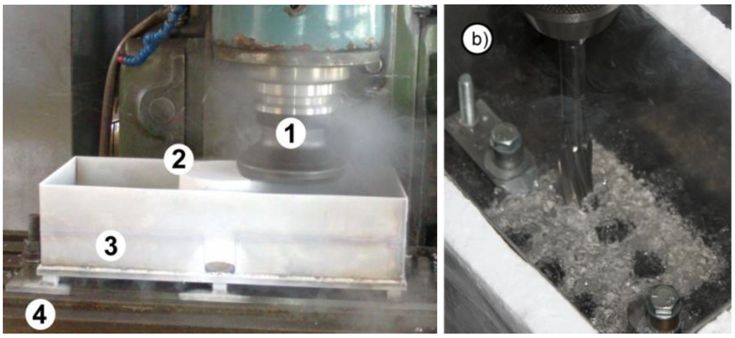
A more advanced method is permanent cooling with liquid nitrogen. In attempts to machine flat surfaces in face milling and make holes with drilling, special holders were built in which workpieces were clamped. Between breaks in machining operations, liquid nitrogen was replenished to maintain the assumed temperature of the workpiece at about minus 185±2
oC (
Figure 5 a, b) [
22,
23].
Changing the temperature value during cutting affects the course of tool wear, dimensional and surface rouhness changes of the workpiece and changes in the surface layer. As a result of friction of the surface of the cutting edge against the workpiece, temperature is emitted, which is distributed unevenly throughout the volume of the layer being removed [
24].
During cutting, several methods are used to reduce the emitted heat and can include:
- -
water, which is the ideal heat removal medium [Sto 2001],
- -
intensive use of cutting fluids (CCS) such as emulsions and oils [
25,
26],
- -
use of volatile emulsion or oil mists (MQLs) in minimal volumes [
25,
26],
- -
water-based machining fluids [
25].
Scientific items give a statistical description of surface roughness and blade wear, stresses in the surface layer, cutting forces, FEM models.
3. Purpose and Methodology of the Study
The purpose of this study is to statically determine the cooling rate of metallic objects as a function of the consumption rate of the cryogenic medium.
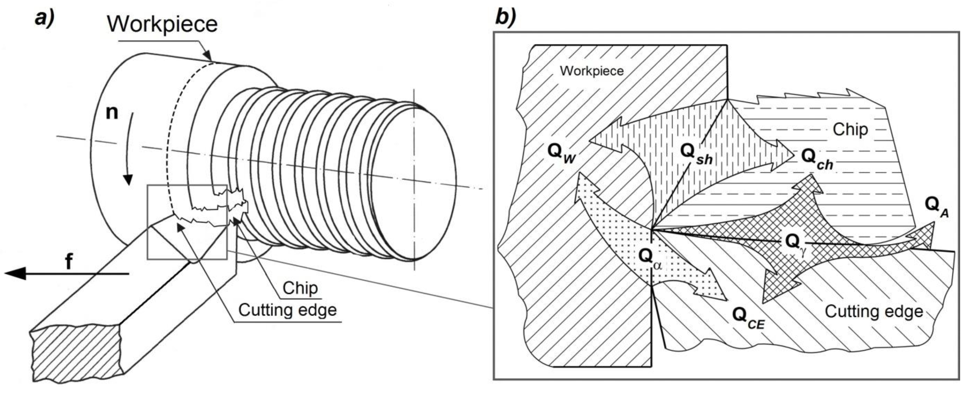
In the machining process (
Figure 6a), heat generated between the cutting edge and the workpiece material is released as a result of the cutting operation (
Figure 6a) [
27] and results in a decrease in the thermal strength and deprivation of the cutting characteristics of the blade [
25].
This interaction is written by the heat balance in the cutting zone (1) [
25,
28].
where:
Qsh - heat generated in the shear zone,
Qγ - heat generated on the blade's leading surface,
Qα - heat generated on the blade application surface,
Qch - heat raised by the chip,
QW - heat penetrating the workpiece,
QCE - heat penetrating the tool,
QA - heat carried into the atmosphere or by the cooling liquid.
The heat balance in the corner region of the blade can be represented according to the model presented in
Figure 6b. The measure of heat exchange between the workpiece - blade - chip is the temperature value expressed in degrees Celsius or Kelvin.
The research problem to be solved boils down to explaining the phenomena of heat removal from the material. In machining, and especially during operations of finishing the machined surface and removing a layer of material with a minimum depth of cut, the question arises: is there a need to cool the entire workpiece? Is it sufficient to cool a selected part of the surface in the cutting zone? This is important in terms of the effectiveness and efficiency of the use of cryogenic fluid during the finishing operations.
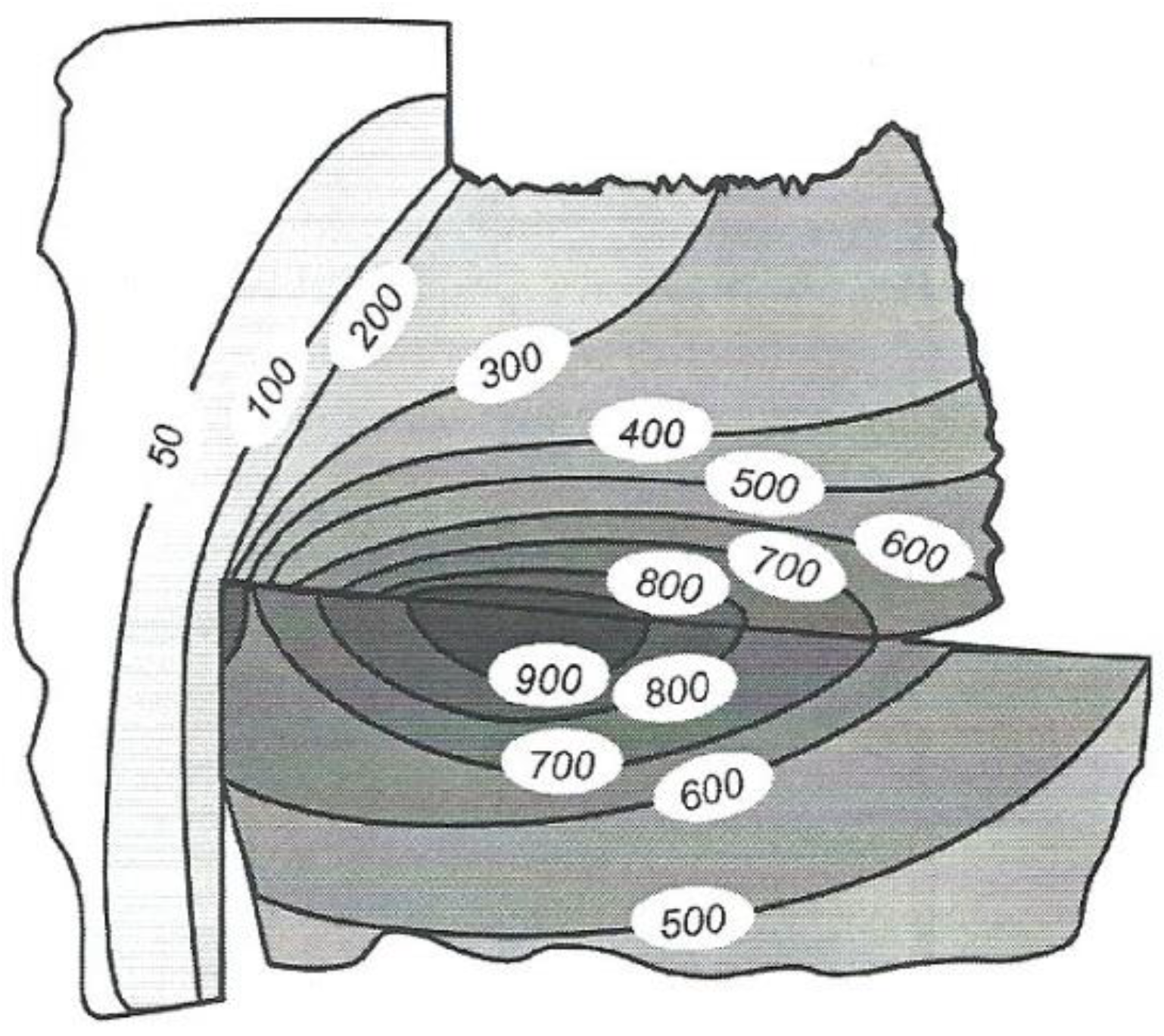
The more interesting practical issue, however, is not the amount of heat given off during cutting, but the temperature value on the cutting edge, workpiece and chip, or generally speaking, the cutting temperature (
Figure 7).
Liquid nitrogen, thanks to its fairly low cost and fairly high cooling properties, has a share in material processing. Unfortunately, there are problems with its storage and increased safety requirements, which limits its versatility. In machining, it is known exactly how thick a layer of material is being removed, so it is not necessary to cool more than it was intended. The selection of the optimal cooling time and temperature should be chosen depending on the ability of the substance to conduct heat.
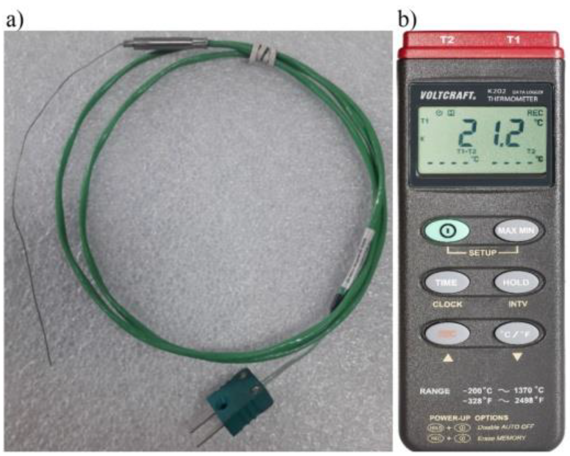
A K-type NiCr-NiAl thermocouple (
Figure 8a), which has the ability to record values in the range of -200 to +1200 °C, was used to measure the variation of temperature values. This thermocouple is characterized by fast response, reliability and the ability to obtain accurate temperature measurements. The accuracy of K-type thermocouple sensors is up to 41 μV/°C. The structure of such a type K thermocouple is the same as any thermocouple and consists of two wires made of different materials. In the K-type, one wire is made of 90% nickel and 10% chromium, while the other is made of 95% nickel, 2% aluminum, 2% manganese and 1% silicon.
The following thermometer used to saved temperature values: VOLTCRAFT Data-Logger Thermometer K202. It is a two-channel temperature value logger that has the ability to measure a range from +1370 °C to -200 °C. The recording time of the recorded periodic waveform frequencies is 1 Hz. The accuracy of the results display is 0.1 °C (
Figure 8b).
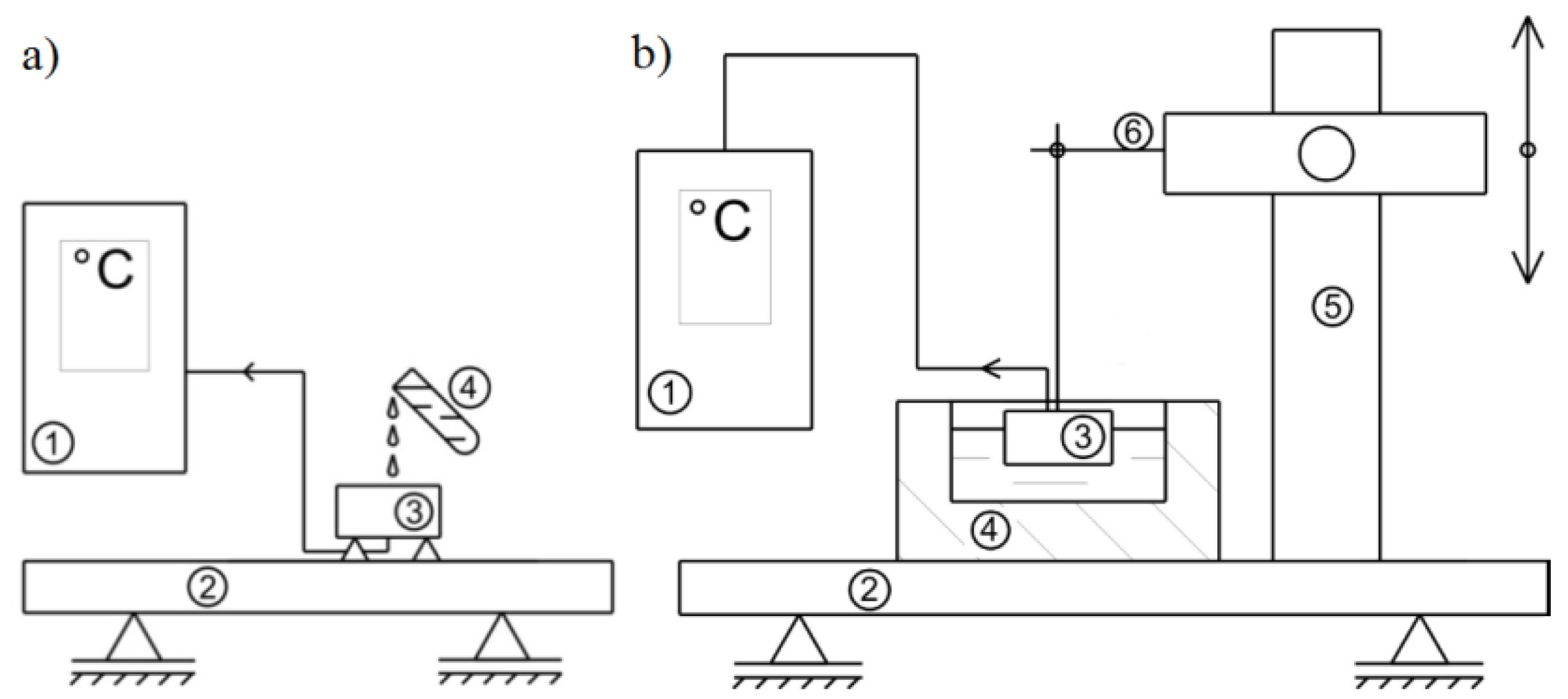
The experiment investigated the change in the temperature of the material over time when cooled with liquid nitrogen. The temperature range was from the laboratory temperature of 21°C to the liquid nitrogen temperature: -195,8°C. In the experiment to statically determine the course of temperature variation during cooling with liquid nitrogen, it was decided to use two test methods. The first concept for measuring the temperature during cooling of an object was to fix a sample of the selected material on the table of the test stand so that the test surface faced upward in the layout of the entire stand. Thus, the measuring tip of the thermocouple was located just below the test surface. In the implementation for the first method of the experiment, a 300 ml container was used, which was filled with a cryogenic substance, namely liquid nitrogen. By slowly tilting the liquid nitrogen container, a stream of liquid was directed and gradually spotted onto the test surface. At this time, the thermocouple sensor began recording the temperature change during the measurement. This course of measurement procedure was performed for material samples with the thermocouple fixed from the test surface at a distance of 1, 2 and 3 mm. The ideal way of conducting the experiment is shown in
Figure 9a. The second method consisted of placing a polystyrene container (3) with a volume of 300 ml, filling it with liquid nitrogen (
Figure 9b). The test specimen was attached to a boom arm so that the material could be freely immersed along with the thermocouple (6). In this case, the test surface was facing downward and the object was partially immersed in liquid nitrogen. Such measurements were made for prepared material samples with the thermocouple fixed at distances of 1, 2 and 3 mm from the test surface –
Figure 9b.
The experiment was conducted under 9 different conditions.
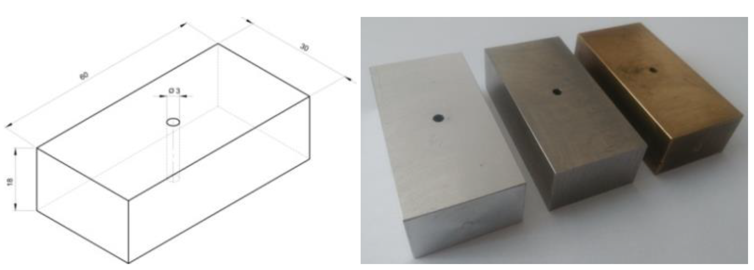
For each material, 3 samples were made, which differed in the distance of the hole to the sample surface at intervals of 1, 2, 3 mm (
Figure 10). The K-type thermocouple was protected by a layer of sealing insulation so that no liquid nitrogen enters the hole during the experiment. The samples were prepared from 3 materials: aluminum AW-2017A with a weight 91 g, stainless steel 316L with a weight 253 g and brass CW617N with a weight 273 g (
Figure 11). Every samples had fixed dimensions of 30x60x18 mm with a hole drilled with a diameter of 3 mm.
4. Results
From the experiments, it can be seen that when measuring the temperature by immersion, there is a rapid change in the temperature value during a certain cooling period. The reason for this phenomenon was the air space of the hole drilled for the placement of the thermocouple. In gases, heat transfer is much faster than in solids.
In the first attempt at experimental testing, the results of the recorded temperature values over time using the pouring of a cryogenic substance such as liquid nitrogen for the listed materials are presented and described in point 3. The studies are shown in
Figure 12 and
Figure 13.
For the AW-2017A material the time of this rapid change was about 10 s but for the brass material 20 s and for steel 35 s. These changes were very rapid, because in a few seconds the change in temperature value decreased by 40°-60° C below zero. Such a phenomenon also proved that the removal of heat from the object does not proceed superficially but can be thought of in a certain vector field indicating certain directions of the fastest decrease in temperature values at particular points of the sample.
It is also noteworthy that the time required for cooling by gravitational delivery of liquid nitrogen to the surface of the sample was up to 90 to 130 s for aluminum and up to 90 to 110 s for brass. For stainless steel material, the time was about 150 s. The situation was completely different for samples immersed in liquid nitrogen.
For the AW-2017A aluminum material (
Figure 12a), initial temperature values were observed in the range of 19, 17 and 12 °C to the thermocouple used. It can be seen from the course of the recorded temperature values over time that cooling proceeds in proportion to the depletion of liquid nitrogen in the container. Here it should be noted that for the thermocouple which was fixed closest to the test surface, -12 °C was obtained after a time of 90 seconds. A similar value, that is, -12 °C, was recorded for the thermocouple that was 3 mm away from the test surface, except that it took 120 seconds for the cryogenic substance to reach the state of no change in temperature value. A thermocouple that was fixed 2 mm from the surface of the aluminum sample under test registered a value of -26 °C in 130 s.
The second trial returned to record temperature values for the CW617N brass material (
Figure 12b). The initial temperature values were in the range of 19-15 °C. It was observed that after 10 seconds of measurement data acquisition, there was an apparent drop in temperature values for the thermocouple, which was fixed 3 mm from the test surface. For this sample, cooling was faster than for the other samples and the temperature value of cooling with liquid nitrogen was obtained -14 °C after a time of 90 sec. The cooling time for the other samples was about 120 sec for the thermocouple fixed 1 mm from the test surface and -13 °C was recorded. For the thermocouple fixed 2 mm from the surface, -12 °C was registered.
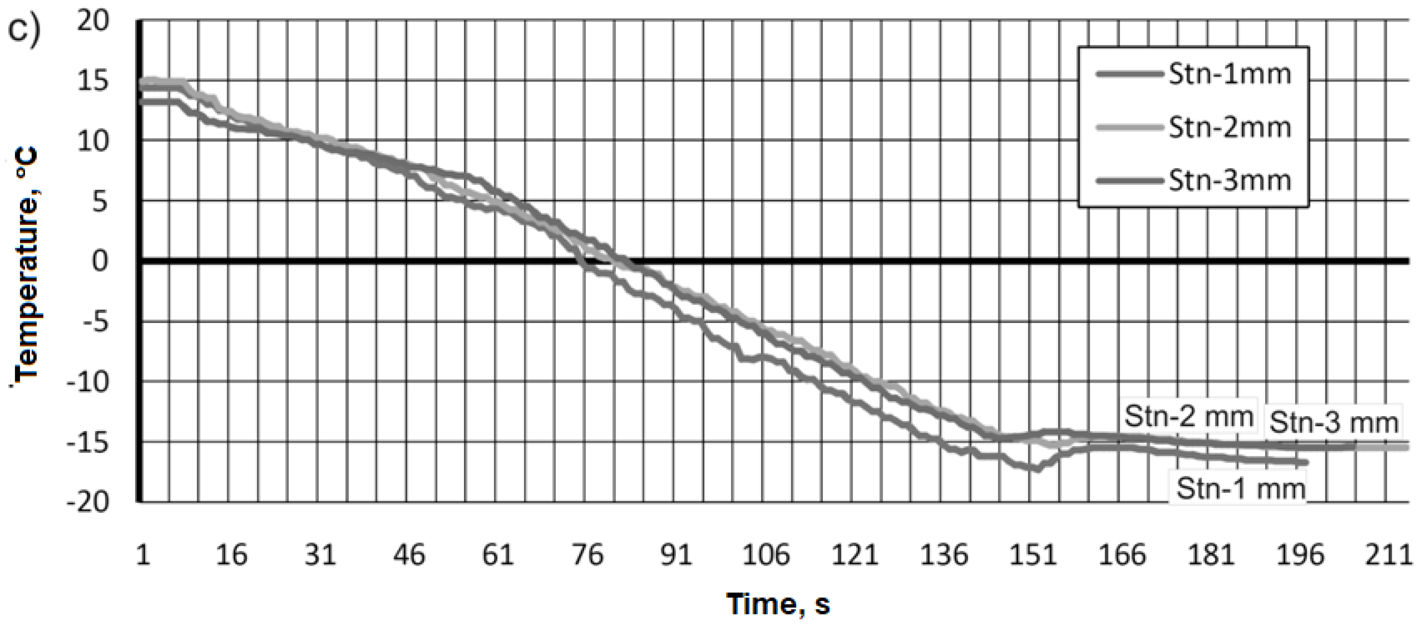
Compared with previous tests for aluminum alloy and brass, a slightly different pattern as a function of time was observed during data acquisition of the cooling temperature values of the 316L stainless steel material sample (
Figure 12c). The form of the function was similar during the recording of temperature values regardless of the thermocouple mounting distance. The initial temperature value was in the range of 15-13 °C, and it took about 151 sec. to reach values of -15 °C and -18 °C.
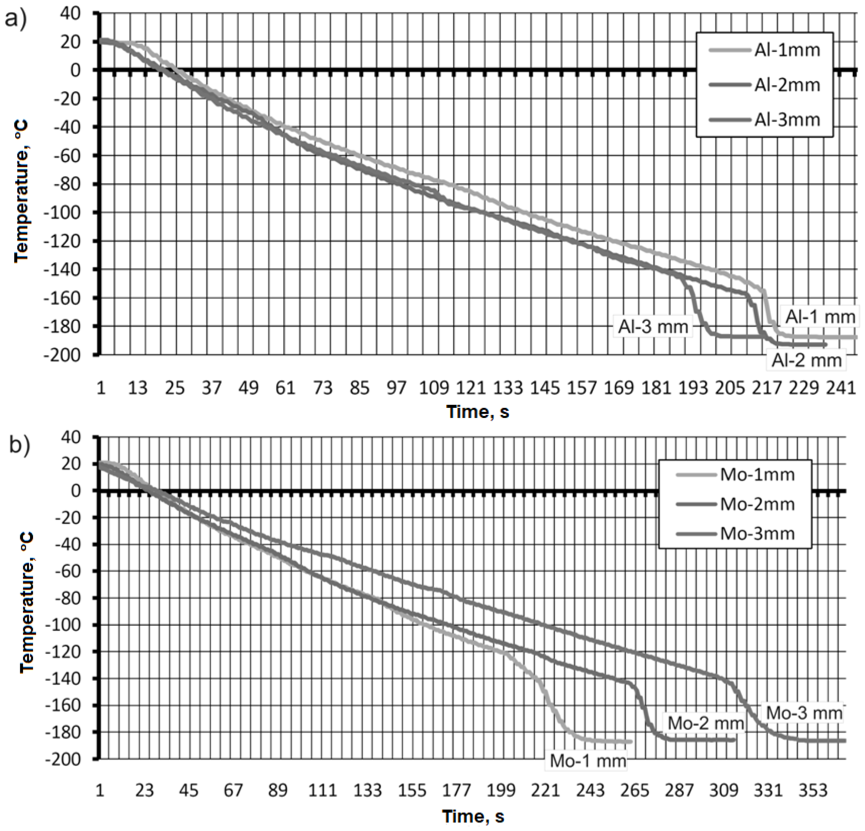
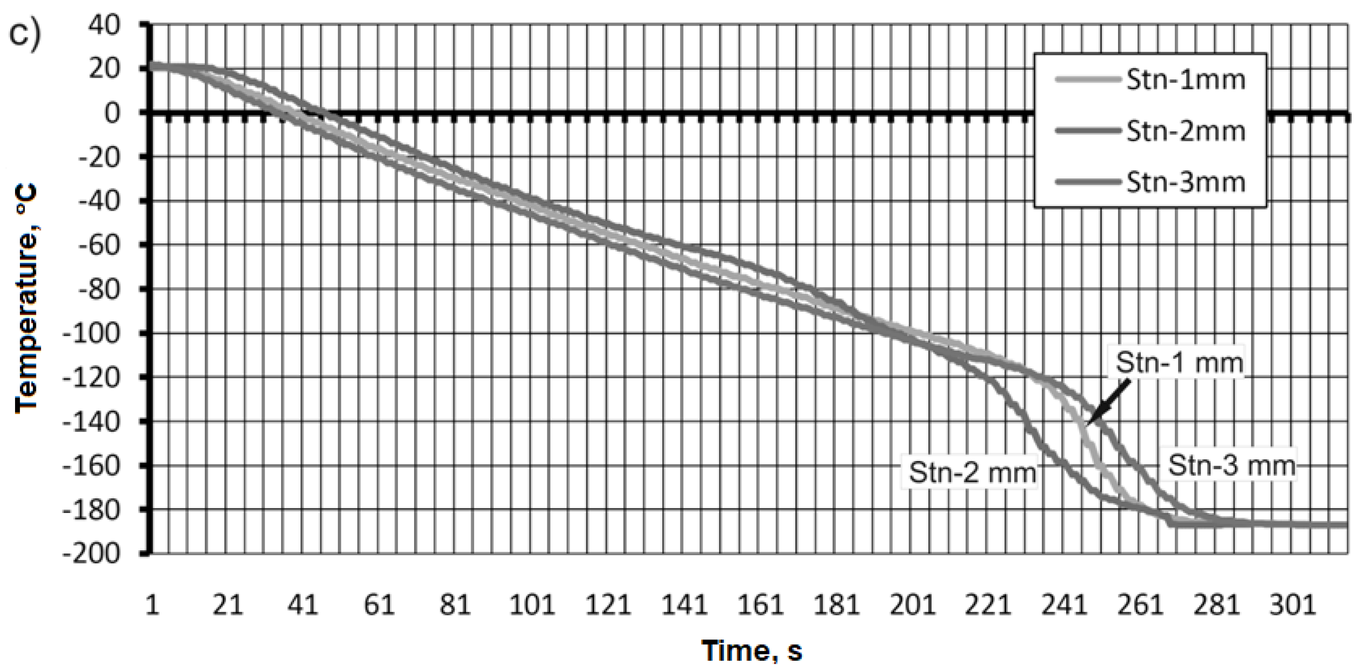
Using the second cooling method, immersion of the test sample in liquid nitrogen was used. The results of the temperature measurement are presented in
Figure 13. The initial temperature value for all test samples was 20 °C.
For the sample made of aluminum alloy AW-2017A, the change in the cooling temperature value was faster for the thermocouple attached 3 mm from the surface of the sample compared to the other thermocouples (
Figure 13a). The value obtained was -188 °C in 201 s. The longest cooling time was recorded for the thermocouple that was attached closest to the sample surface. The temperature value that was recorded was also -188°C but at a time of 224 s. A similar temperature value was recorded for a thermocouple attached 2 mm from the surface of the sample (
Figure 13a).
During cooling by immersion of the sample made of CW617N brass material, the following time course of temperature values was recorded (
Figure 13b). The fastest cooling was performed in the sample, where the thermocouple was fixed as close as possible to the test surface, and after a time of 243 sec. -185 °C was reached. The same temperature value was obtained for the thermocouple attached 2 and 3 mm from the sample surface. However, the timing was decidedly different and 283 sec and 348 sec were required for sweetening. This is illustrated in
Figure 13b.
For the 316L stainless steel alloy, the data as a function of measurement time were similar to each other. The values we were able to record were -188 °C in the range of 270-280 seconds, depending on the mounting of the thermocouple (
Figure 13c).
4. Conclusions
The method by pouring liquid nitrogen allowed materials to be cooled from -12 to -18 °C. In the method by immersion of the material, a temperature value of -188°C on average was achieved at a flow rate of 300 ml of liquid nitrogen.
In the cooling process in the method by immersion, the function took a form close to linear and this can be seen for all samples.
After reaching -120 and -140 °C, there was a sharp decrease in the temperature value. Such a phenomenon was recorded for all materials that were used in the experiment. Presumably, this could have been influenced by the space in which the thermocouple was embedded in the samples.
The time required to cool the material by immersion was 35% longer for AW-2017A aluminum, 50% for CW617N brass and 46% for 316L stainless steel compared to the method by pouring liquid nitrogen.
Analyzing the results of the experiments carried out, a statement is made about the effectiveness of the effective methods used to deliver cryogenic liquid to the cutting zone. Classical nozzles and micro-dielectrodes for cooling the cutting zone really only reduce the temperature of the air in the cutting zone and not the workpiece material. Publications explain or focus mainly on issues and phenomena occurring in the workpiece material. What is needed is expere-mental data on the effect of cryogenic fluid on the cutting edge. Results of research work exist only on the wear of the blade during cutting. There is no information on how the cutting temperature, material changes, deformation and stresses prevailing in the blades during turning, milling, drilling, grinding change.
The phenomenon, which has been described as "warm bobbles" [
13], prevents efficient heat removal from the workpiece. If the kinematic movements of the blade and workpiece are added, the phenomenon of cooling the workpiece decreases even further, due to the centrifugal force of rotating or performing reciprocating movements of the workpieces during cutting.
Author Contributions
The individual contributions of the authors: conceptualization, J.C. and L.Z.; methodology, J.C.; investigation, J.C., L.Z.; software, J.C., L.Z., data curation, J.C.; validation, L.Z.; writing—original draft preparation, L.Z.; writing—review and editing, J.C.; visualization, L.Z.; supervision, J.C.; All authors have read and agreed to the published version of the manuscript.
Conflicts of Interest
The authors declare no conflict of interest.
References
- BARTOSZUK, M. , Studies of thermal interactions in the cutting zone for AISI 321 steel. School of Machining - Efficient Manufacturing, Wrocław, 2012.
- BARTOSZUK, M. , Modeling of heat flow and temperature distribution in the cutting zone for carbide inserts, Opole University of Technology Publishing House, Studies and monographs, Notebook No. 342, Opole, 2013.
- DHAR, N. , PAUL S., CHATTOPADHYAY A., The role of cryogenic cooling on cutting temperature in steel turning. J. Manuf. Sci. Eng. 2002, 124, 146–154. [Google Scholar] [CrossRef]
- BALAN, A.S.S. , VIJAYARAGHAVAN L., KRISHNAMURTHY R., KUPPAN P., OYYARAVELU R., An experimental assessment on the performance of different lubrication techniques in grinding of Inconel 751, Journal of Advanced Research, 7, Cairo University, 2016. [CrossRef]
- SARTORIA, S. , BORDINA A., GHIOTTIA A., BRUSCHIA S., Analysis of the surface integrity in cryogenic turning of Ti6Al4V produced by Direct Melting Laser Sintering, Procedia CIRP 45, 2016.
- SHOKRANIA, A. , DHOKIAA V., NEWMANA T.S., Cryogenic high speed machining of cobalt chromium alloy, Procedia CIRP 46, 2016.
- JAWAHIRA, I.S. , PULEOB D.A., SCHOOPA J., Cryogenic machining of biomedical implant materials for improved functional performance, life and sustainability, Procedia CIRP 46, 2016.
- KROLCZYK, G.M. , MARUDA R. W., KROLCZYK J.B., WOJCIECHOWSKI S., MIA M., NIESłONY P., BUDZIK G., Ecological trends in machining as a key factor in sustainable production - A review, J. Clean. Prod. 2019, 218, 601–615. [Google Scholar] [CrossRef]
- MANG, T. , Encyclopedia of Lubricants and Lubrication. Springer Berlin Heidelberg. 2014. [Google Scholar]
- PUSAVEC, F. , KOPAC, J., Sustainability assessment: cryogenic treatment of Inconel 718. Strojniski vestnik-J. Mech. Eng. 2011, 57, 637–647. [Google Scholar] [CrossRef]
- SIVAIAHA, P. , CHAKRADHARB D., Effect of cryogenic coolant on turning performance characteristics when machining 17-4 PH stainless steel: A comparison with MQL, wet, dry machining. CIRP Journal of Manufacturing Science and Technology 2018, 21, 86–96. [Google Scholar] [CrossRef]
- WIKA, K.K. , LITWA P., HITCHENS C., Impact of supercritical carbon dioxide cooling with Minimum Quantity Lubrication on tool wear and surface integrity in the milling of AISI 304L stainless steel. Wear, 1691. [Google Scholar] [CrossRef]
- HRIBERSEK, M. , SAJN V. , PUSAVEC F., RECH J., KOPAC J., The Procedure of Solving the Inverse Problem for Determining Surface Heat Transfer Coefficient between Liquefied Nitrogen and Inconel 718 Workpiece in Cryogenic Machining, Procedia CIRP 2017, 58, 617–622. [Google Scholar] [CrossRef]
- HONG SY, DING Y. , Cooling methods and cutting temperatures in cryogenic machining of Ti-6Al-4V. International Journal of Machine Tools and Manufacture 2001, 41, 1417–1437. [Google Scholar] [CrossRef]
- HONG SY, DING Y. Micro-temperature manipulation in cryogenic machining of low steel. J. Mater. Process. Technol. [CrossRef]
- ŻURAWSKI, Ł. , PAłKA T., ZAWADA- TOMKIEWICZ A., Improving the efficiency of milling of flat surfaces. School of Machining - Efficient Manufacturing, Wrocław, 2012.
- STORCH, B. , PAłKA T., ŻURAWSKI Ł., ZAWADA- TOMKIEWICZ A., Effect of tool wear on surface roughness after cryogenic turning. School of Machining - Science and Industry, Wroclaw/Opole, 2011.
- HONG, S.Y. , DING Y., Cooling Approaches and Cutting Temperatures in Cryogenic Machining of Ti-6Al-4V, International Journal of Machine Tools and Manufacture 41, 2001.
- HONG, S.Y. , MARKUS I., JEONG W., New Cooling Approach and Tool Life Improvement in Cryogenic Machining of Titanium Alloy Ti-6Al-4V, International Journal of Machine Tools and Manufacture, 41, 2001. [CrossRef]
- YILDIZ, Y. , NALBANT M., A review of cryogenic cooling in machining processes, International Journal of Machine Tools & Manufacture, 48, 2008. [CrossRef]
- STORCH, B. : Application of liquid nitrogen for cooling the cutting zone, Scientific Journals of the Poznan University of Technology, Mechanical Engineering and Production Management, No. 11, 2009.
- ŻURAWSKI, Ł. , STORCH B., Effect of tool wear on surface roughness after milling of aluminum alloy in cryogenic machining. School of Machining - Synergy of Science and Industry, Międzyzdroje-Szczecin, 2014.
- PAłKA, T. , STORCH B., ŻURAWSKI Ł., ZAWADA- TOMKIEWICZ A., Efficiency of operation in liquid nitrogen of high-speed steel reamers. School of Machining - Efficient Manufacturing, Wrocław, 2012.
- ŻEBROWSKI, H. , et al.: Manufacturing Techniques. Chip machining, abrasive machining, erosion machining, 2004. [Google Scholar]
- STORCH, B. , Fundamentals of machining, University Publishing House of the Koszalin University of Technology, Koszalin, 2001.
- LEPPERT, T. , Shaping by turning the surface layer in dry cutting conditions or with minimal cooling and lubrication of the tool, Dissertation No. 151, University Publications of Technology and Life Sciences, Bydgoszcz, 2011.
- FILIPOWSKI, R. , MARCINIAK M. Machining and erosion techniques, 2000. [Google Scholar]
- SAJGALIK, M. , PILC J., BOROVSKY R., SVITANA M., Simultaneous monitoring of dynamic processes in the cutting zone in turning of superalloys by using thermovision and high-speed scanning. School of Machining - Efficient Manufacturing, Wroclaw, 2012.
- JEMIELNIAK, K. 2004.
|
Disclaimer/Publisher’s Note: The statements, opinions and data contained in all publications are solely those of the individual author(s) and contributor(s) and not of MDPI and/or the editor(s). MDPI and/or the editor(s) disclaim responsibility for any injury to people or property resulting from any ideas, methods, instructions or products referred to in the content. |
© 2024 by the authors. Licensee MDPI, Basel, Switzerland. This article is an open access article distributed under the terms and conditions of the Creative Commons Attribution (CC BY) license (https://creativecommons.org/licenses/by/4.0/).
