1. Introduction
Titanium alloys have found wide application in various industries, such as aircraft, rocket and shipbuilding, medical and space technologies, food industry, and energy. This is primarily due to its lightness, ductility, and high corrosion resistance. Despite a number of advantages of titanium-based alloys as structural materials, their use as functional materials is limited by high toughness and low machinability, as well as low wear resistance. To solve these problems, protective coatings are often used in functional components and mechanisms made of titanium materials. Among the widely used technologies for creating protective coatings are spraying and fusion of wear-resistant coatings [
1,
2,
3,
4,
5,
6,
7], thermal and plasma electrolytic oxidation [
8,
9,
10,
11,
12,
13,
14,
15,
16,
17,
18,
19,
20,
21,
22].
The intensive development of plasma electrolytic technologies has not left this issue aside. In addition to the previously mentioned plasma electrolytic oxidation, used to create protective ceramic-like coatings, there are two more types of the method: plasma electrolytic polishing and plasma electrolytic chemical-thermal treatment. Polishing in electrolysis plasma is used on an ongoing basis to solve problems of reducing the roughness and decorating of metal surfaces, as well as removing coatings from them [
23,
24,
25,
26,
27,
28,
29]. Chemical-thermal treatment in electrolysis plasma solves the main problems of traditional methods of chemical-thermal treatment (surface hardening and concomitant improvement in the mechanical characteristics of the surface and product), and can additionally be used to increase wear resistance and corrosion resistance due to the formation of a multiphase structures.
The largest amount of work in the field of plasma electrolytic chemical-thermal treatment has been carried out for the treatment of steels [
30,
31,
32,
33,
34,
35,
36,
37,
38,
39,
40,
41,
42,
43]. The effect of the complex effect of changes in the structural-phase composition and surface morphology on increasing wear resistance and corrosion resistance is shown. The processing of titanium alloys by plasma electrolytic chemical-thermal treatment has also been studied, but special cases of processing of certain alloys were mainly considered [
44,
45,
46,
47,
48,
49,
50,
51,
52,
53,
54,
55,
56,
57,
58]. Positive results were shown in increasing hardness, wear resistance and corrosion resistance. Among the types of processing considered, attention is paid to nitriding, carburizing and nitrocarburizing. Boriding is occasionally considered. In this work, it is proposed to expand the methods of diffusion saturation of titanium alloys – to study the process of joint saturation of CP-Ti with boron and carbon.
One of the key disadvantages of using plasma electrolytic treatment is the uncontrolled formation of a multiphase structure of the surface oxide layer, which can have significant irregularities, as well as weak areas that are prone to peeling during operation, especially in frictional contact. In this regard, this work proposes a variant of complex surface treatment, which consists of plasma electrolytic chemical-thermal treatment and subsequent polishing. This technology will allow finishing treatment to be carried out immediately after the hardening treatment, removing all irregularities and weak areas of the outer oxide layer.
2. Materials and Methods
2.1. Materials
Cylindrical samples (∅ 10 mm × 15 mm) of CP-Ti (99.33 wt.% Ti; 0.25 wt.% Fe; 0.2 wt.% O, 0.1 wt.% Si; 0.07 wt.% C; 0.04 wt.% N; 0.01 wt.% H) were ground with SiC abrasive paper grit size P120 to Ra~1.0 μm and ultrasonically cleaned with acetone.
2.2. Processing
These samples were subjected to duplex surface treatment, which includes sequential anodic PEBC and PEP. PEBC was carried out in a cylindrical electrolyzer with an axially symmetric electrolyte flow supplied through a nozzle located at the bottom of the electrolyzer (
Figure 1).
In the upper part of the electrolyzer, the electrolyte was overflowing into the sump and was further pumped through a heat exchanger at a rate of 2.5 L/min. The solution temperature was measured using a thermosensor, placed at the bottom of the chamber and maintained at 22 ± 2 °C. The samples were connected as the positive output, and the electrolyzer was connected as the negative output of the 15 kW DC power supply. An aqueous solution of boric acid (3 wt.%), glycerin (8 wt.%) and ammonium chloride (10 wt.%) was used as the working electrolyte. The PEBC time was 5 minutes and carried out at temperatures of 800, 850, 900, and 950 °C. After PEBC, the samples were quenched in the electrolyte in which they were treated (hardening).
PEBC samples were further polished PEP in an aqueous solution of ammonium fluoride (4%) at a temperature of 90 °C. The operating voltage during PEP was 250 V. The electrolyte flow rate was 1 L/min. PEP times were 1, 3 and 5 minutes.
2.3. Study of the Surface Morphology and Microstructure
The Micromed MET (Observing devices, St. Petersburg, Russia) optical metallographic microscope with digital image visualization served to study the surface morphology and microstructure of cross-section of the CP-Ti samples.
2.4. Study of the Phase Composition
The phase composition of PENC layers was determined using a PANalytical Empyrean X-ray diffractometer (XRD) (Malvern Panalytical, Malvern, UK) with CoKα radiation using PANalytical High Score Plus software, program [
59] and ICCD PDF-2 and COD [
60].
2.5. The Microhardness Measurement
The microhardness of the PEBC layers was measured using a Vickers microhardness tester (Falcon 503, Innovatest Europe BV, Maastricht, The Netherlands) under a load of 0.1 N.
2.6. The Surface Roughness and Weight of Samples Measurement
The geometric characteristics of the surface were measured using a Hommel tester t8000 profilometer (Jenoptik, Jena, Germany).
Weight measurements were performed on a CitizonCY224C electronic analytical balance (ACZET (Citizen Scale), Mumbai, India).
2.7. Study of Tribological Properties
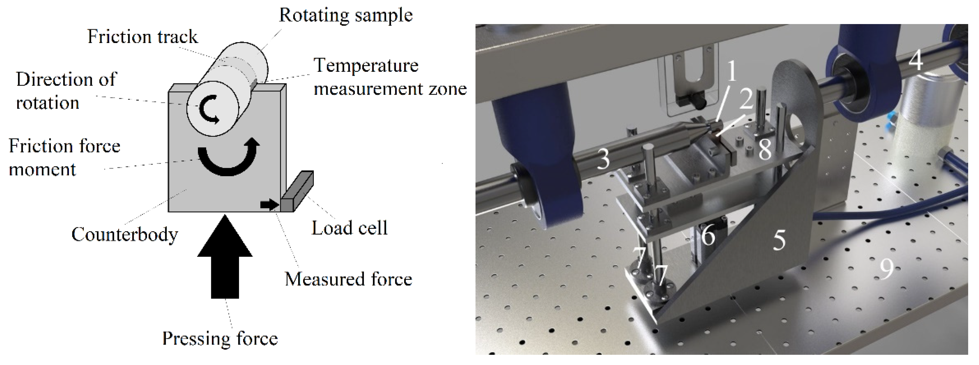
The “shaft-block” friction scheme was used in friction tests (
Figure 2). The counterbody was made of tool alloy steel (wt.%: 0.9–1.2 Cr, 1.2–1.6 W, 0.8–1.1 Mn, and 0.9–1.05 C) in the form of a plate with a semicircular notch 10 mm in diameter enclosing the surface of the sample. The cylindrical sample was rotated, and a counterbody was pressed against it. Friction tests were carried out in dry friction mode under a load of 10 N. The sliding speed of the sample along the counterbody was 1.555 m/s. The sliding distance was 1000 m. The temperature of the friction contact was measured on the friction track directly at the exit from the contact area using an MLX90614 digital infrared thermometer (Melexis Electronic Technology, Shanghai, China).
2.8. Study of the Corrosion Resistance
The corrosion resistance of the samples was determined by potentiodynamic polarization curves using a Biologic SP-150 potentiostat-galvanostat (Biologic Science Instruments, France) with a standard three-electrode cell in Ringer’s solution (8.6 g/L NaCl, 0.3 g/L KCl, 0.25 g/L CaCl2), at a sweep rate of 1 mV/s. Before the corrosion testing, the samples were cleaned with acetone in the ultrasonic bath for 5 min, then washed with distilled water and dried until their weight stabilized. Further, each samples’ surface was insulated by a dielectric mask with a circular aperture with a 0.132 mm2 area located at the distance of 2 mm from the lower edge of the sample. Graphite was used as the auxiliary electrode. The saturated silver chloride electrode served as the reference one. The working electrode (sample) was kept in the Ringer’s solution for 60 min before testing to steady the constant value of the corrosion potential. The corrosion current density was determined by Tafel’s extrapolation of the polarization curves using EC-Lab software (v.11.43).
3. Results and discussion
3.1. Structure, Composition, Morphology and Roughness of CP-Ti Surface after PEBC
During the PEBC, the processes of high-temperature oxidation, anodic dissolution and diffusion saturation simultaneously occur on the surface, which is typical for anodic plasma electrolytic chemical-thermal treatment [
37,
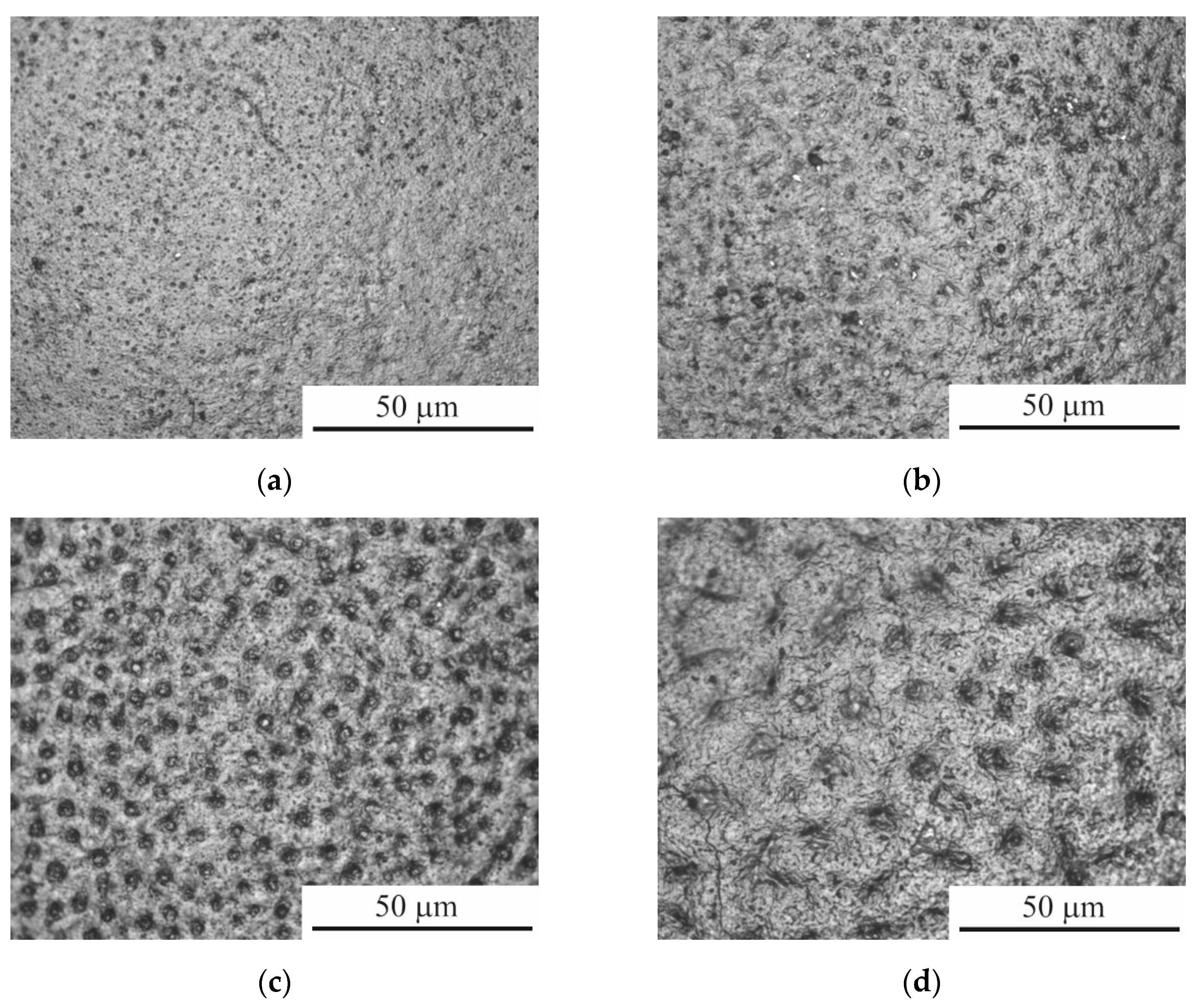
42]. The result of high-temperature oxidation was the formation of an oxide layer containing many pores, the sizes of which increase with increasing treatment temperature (
Figure 3). The composition of the oxide layer, according to X-ray analysis, includes oxides of the composition TiO
0.325, TiO
2 (rutile and anatase) and Ti
3O (
Figure 4).
Anodic processes are characterized by electrochemical dissolution of the surface, which is accompanied by a weight loss of the samples (
Table 1) and affects its morphology. In this case, we can talk about competition between the processes of oxidation and anodic dissolution. When surface oxidation dominates, an increase in roughness is observed, and when anodic dissolution prevails, the opposite trend is observed. The surface roughness
Ra of samples after PEBC at 950 °C increases from 1.00 ± 0.10 µm (untreated sample) to 1.27 ± 0.56 µm (
Table 1). At lower processing temperatures, surface roughness decreases. The maximum reduction in average roughness to 0.46 ± 0.09 μm is observed after PEBC at 800 °C, which is 2 times lower than that of the untreated sample. Further, with increasing processing temperature, the roughness increases as a result of the intensification of high-temperature oxidation. The data obtained indicate the predominance of anodic dissolution at temperatures of 800, 850 and 900 °C and high-temperature oxidation at 950 °C.
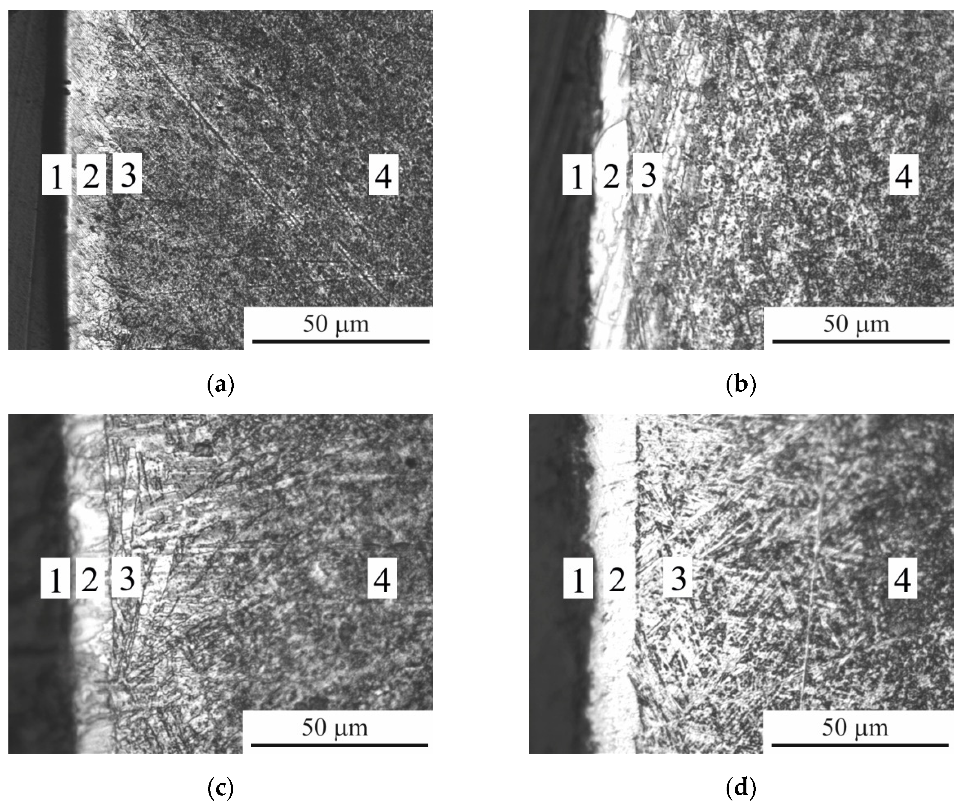
According to metallographic analysis, under the surface oxide layer as a result of diffusion saturation, the formation of a PEBC layer is observed (
Figure 5), which, according to X-ray analysis, contains titanium carbide, as well as a solid solution of diffusants (
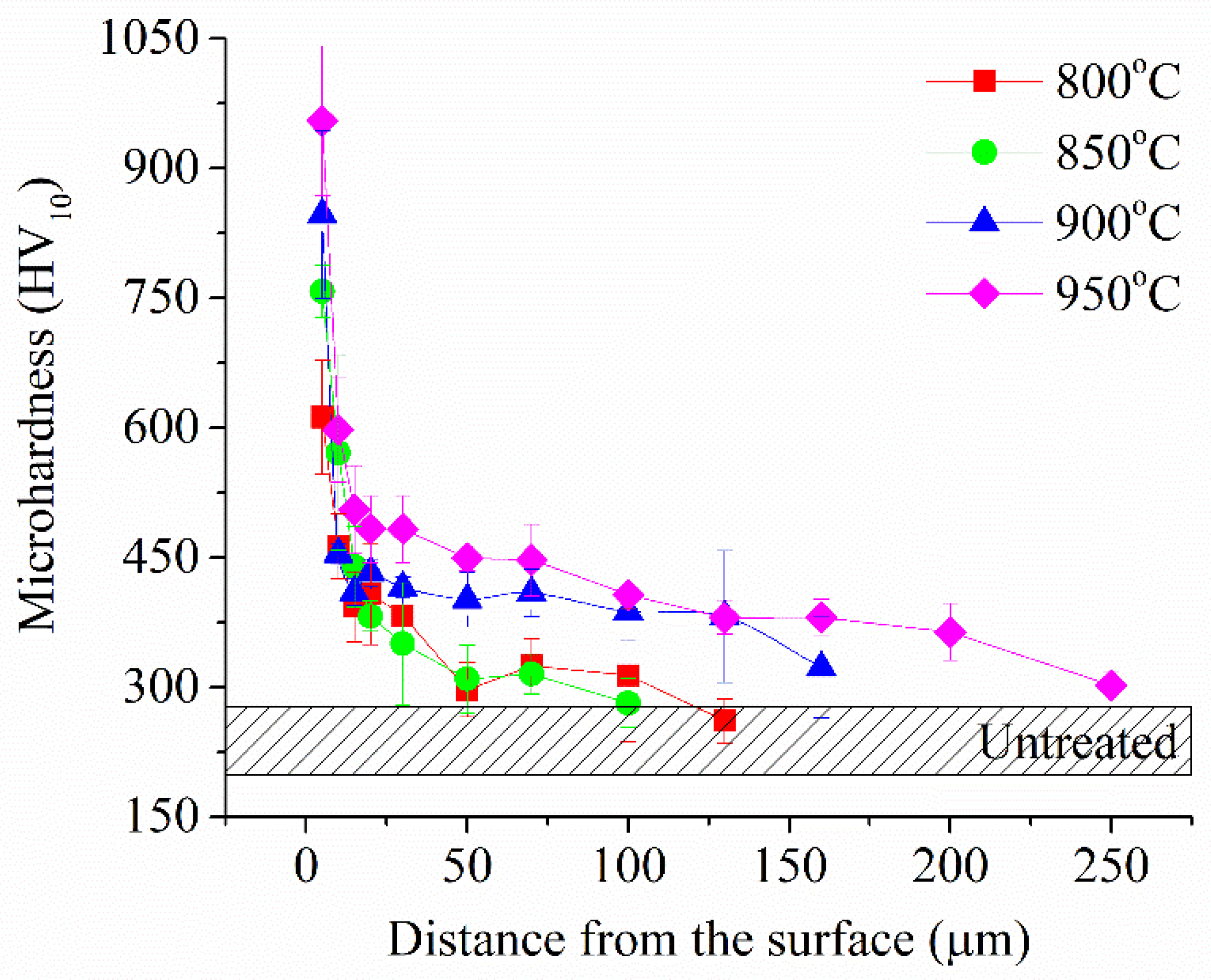
Figure 4). Metallographically, PEBC layer consists of an unetched carbide layer and a diffusion layer. The resulting PEBC layer has increased microhardness, which increases with increasing PEBC temperature and is more than 3 times higher than the value of the initial microhardness (
Figure 6). The thickness of the hardened layer, in turn, after treatment at 950 °C reaches 200 μm.
3.2. Tribological Properties of CP-Ti Surface after PEBC
As a result of tribological tests after treatment at all temperatures of PEBC, the friction coefficient decreases compared to the untreated sample (
Table 1). The greatest reduction in the friction coefficient occurs after PEBC at 800 °C. It is under these conditions that the minimum wear rate is observed.
An increase in the treatment temperature entails a linear increase in weight wear, which on samples after treatment at 950 °C exceeds the value of the untreated sample. In this case, the friction coefficient also increases and has similar values in the temperature range from 850 to 950 °C.
An increase in weight wear with increasing processing temperature can be associated with an increase in the porosity of the oxide layer, which will be destroyed by friction. Analysis of the morphology of the friction tracks indicates oxidative wear of the samples after PEBC, while on the friction tracks of the untreated sample, in addition to traces of oxidative wear, traces of microcutting are visible (
Figure 7). In this case, the oxide layer formed during PEBC will wear off and prevent the rapid destruction of oxidation products during tribocoupling, which have a lubricating effect when sliding surfaces. When testing an untreated sample, this does not happen; oxidation products during friction are quickly destroyed and the material is destroyed by cutting by wear products.
3.3. Corrosion Properties of CP-Ti Surface after PEBC
The results of corrosion tests in Ringer’s solution showed an increase in corrosion current density after PEBC (
Table 1). A close value of the corrosion current to the initial surface is observed only on samples processed at a temperature of 800 °C. An increase in the PEBC temperature leads to an increase in the corrosion current. This pattern can be associated with the development of surface relief - an increase in the porosity of the oxide layer, which will accumulate corrosive agents. In this case, a correlation between the corrosion current density and surface roughness is observed.
Thus, to obtain a surface with maximum microhardness, it is more expedient to carry out PEBC at a temperature of 950 °C. The tribological and corrosion properties of PEBC samples will be determined primarily by the surface morphology, which in fact represents the morphology of the oxide layer. The outer oxide layer, which influences the tribological and corrosion behavior of the surface, can be partially or completely removed using PEP. To study the effect of PEP on surface properties, it is proposed to use samples after treatment at a temperature of 950 °C, which have maximum microhardness.
3.4. Structure, Composition, Morphology and Roughness of CP-Ti Surface after Duplex Processing (PEBC+PEP)
Polishing in ammonium fluoride solution for varying durations revealed that after 1 minute of PEP, the visible pores of the oxide layer are removed (
Figure 8b); while at the same time, the surface roughness increases (
Table 2). Increasing the PEP duration to 3 minutes made it possible to significantly smooth out the surface relief (
Figure 8c) and reduce roughness. After 5 minutes of polishing, the oxide layer is completely removed (
Figure 8d), and the roughness increases slightly.
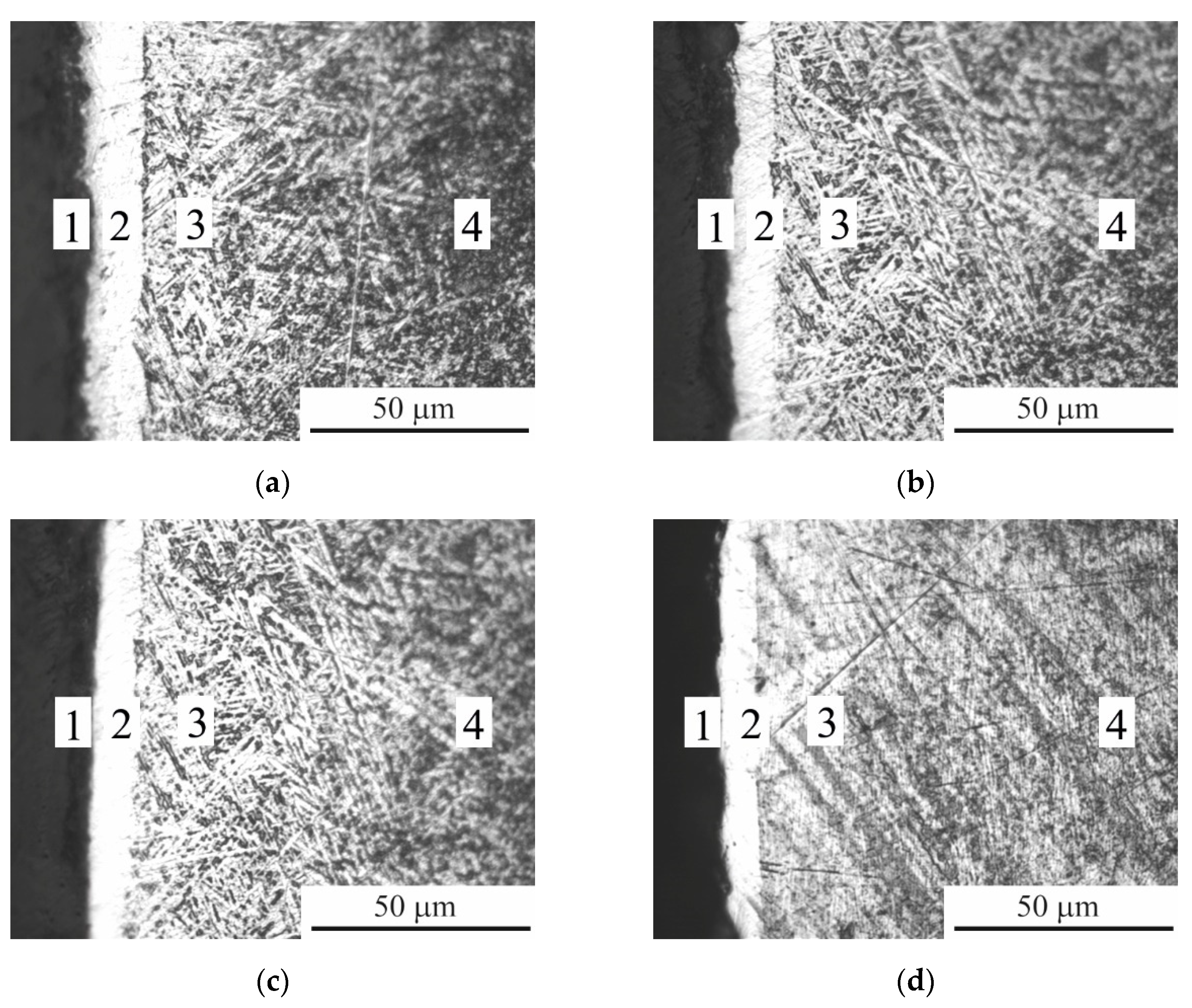
Analysis of the microstructures of the surface layers showed that after PEP for 1 and 3 minutes, the oxide and hardened layers are preserved (
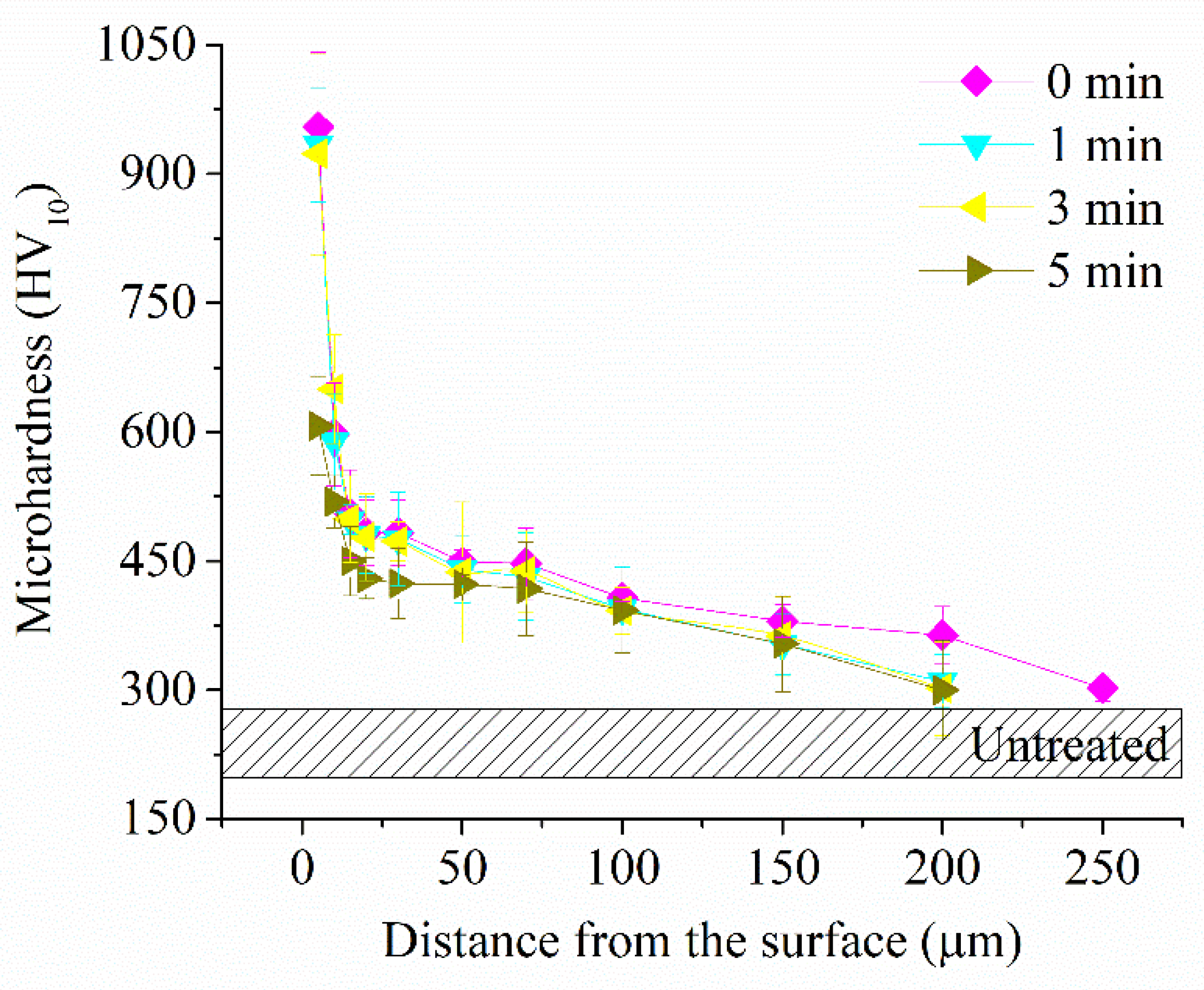
Figure 9b,c). Microhardness in this case also does not change (
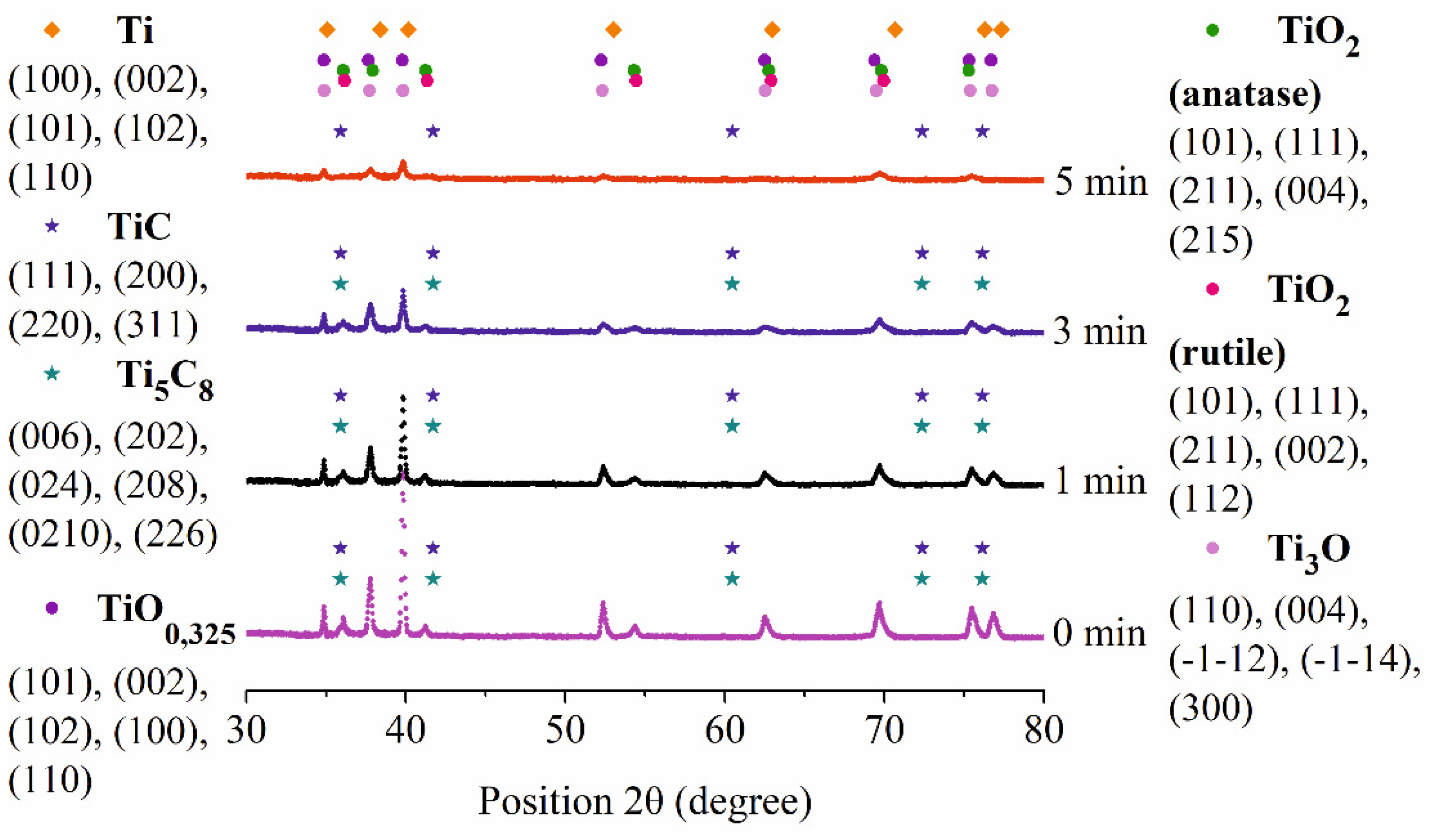
Figure 10). According to X-ray analysis, a decrease in the intensity of the peaks of titanium oxides with preservation of carbides is observed (
Figure 11). Increasing the duration of PEP to 5 minutes leads to the removal of the oxide layer and part of the hardened one (
Figure 9d) with a decrease in microhardness (
Figure 10). The absence of titanium carbide indicates partial dissolution of the hardened layer (
Figure 11).
3.5. Tribological Properties of CP-Ti Surface after Duplex Treatment (PEBC+PEP)
Tribological tests showed that after polishing PENC samples, a decrease in the friction coefficient is observed (
Table 2). The largest reduction in the friction coefficient from 0.393 to 0.231 is observed in samples subjected to PEBC followed by PEP for 3 minutes. In this case, weight wear is also minimal, 3.1 times lower compared to the untreated sample and 3.3 times lower compared to the PEBC sample.
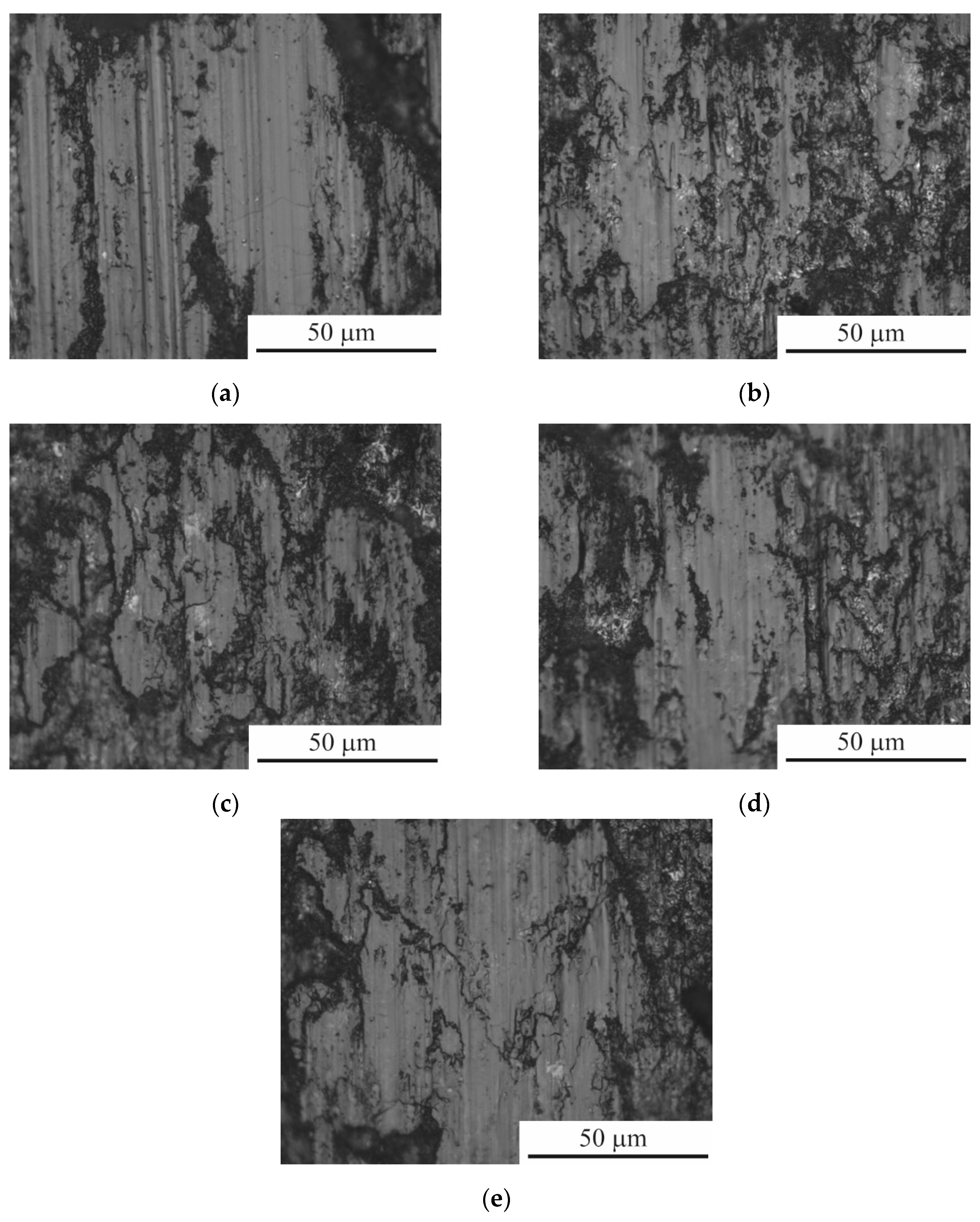
After PEP for 1 and 3 minutes, dark oxide films are visible on the friction tracks (
Figure 12). Oxide films shielding the friction contact surfaces have lower hardness than the surface hardened layer of the sample. This leads to the fact that during friction it is removed from the surface of a metal body more easily than the surface layer. Wear occurs as a result of the removal of the oxidized layer. In addition, the oxide film can act as a friction lubricant. After five minutes of polishing, the leading wear mechanism changes. The photograph of the friction track shows stripes in the sliding direction without sharp boundaries, showing plastic deformation of the base metal by the roughness protrusions of the counter body. There are practically no traces of dark oxide films in the photographic field and wear occurs directly along the metal base material, which explains the higher values of both the friction coefficient and weight wear.
3.6. Corrosion Properties of CP-Ti Surface after Duplex Treatment (PEBC+PEP)
Subsequent PEP of the PEBC surface in an ammonium fluoride solution favors a decrease in the corrosion current density (
Table 2). After just 1 minute of polishing, the corrosion current decreases by 5.2 times and becomes close to the value of the untreated sample. The greatest reduction occurs after 3 minutes of PEP - the corrosion current density becomes 22.2 times lower than the PEBC surface and 4 times lower than the untreated surface. After 5 minutes of PEP, there is an increase in corrosion current density, but to a lower value than that of the untreated sample.
The results obtained indicate a correlation between corrosion current density and morphology and roughness surface. The formation of a morphologically homogeneous surface, including oxides and having low roughness, will determine the corrosion resistance of the PEBC surface of CP-Ti.
4. Conclusions
Based on the results of the work, a variant of complex treatment of the surface of CP-Ti was proposed, consisting of plasma electrolytic borocarburizing and subsequent polishing. This technology makes it possible to form on the surface of CP-Ti a hardened layer up to 200 μm thick with a microhardness of up to 950 HV, including carbides and a solid solution of boron and carbon. Polishing in electrolysis plasma in the same electrolyzer after hardening treatment makes it possible to remove unevenness and weak areas of the outer porous oxide layer. A comprehensive reduction in roughness and surface hardening contributes to increased wear resistance and corrosion resistance. Weight wear is reduced by 3 times due to a change in the frictional interaction mode from microcutting to oxidative wear, and the corrosion current density in Ringer’s solution is reduced by 4 times after PEBC in a solution of boric acid, glycerin and ammonium chloride at 950 °C for 5 minutes and subsequent PEP in ammonium fluoride solution at 90 °C at 250 V for 3 minutes.
Author Contributions
Conceptualization, M.A.V. and S.A.K.; methodology, S.A.K.; validation, M.A.V.; formal analysis, I.V.S.; investigation, I.V.T., T.L.M. and A.P.M.; resources, S.N.G.; writing—original draft preparation, M.A.V., I.V.T., T.L.M. and I.V.S.; writing—review and editing, S.A.K. and S.N.G.; visualization, S.A.K. and A.P.M.; supervision, I.V.S.; project administration, S.N.G.; funding acquisition, M.A.V. All authors have read and agreed to the published version of the manuscript.
Funding
This research was carried out with the financial support of the Russian Science Foundation within the framework of scientific project No. 24-19-00811.
Data Availability Statement
Not applicable.
Acknowledgments
This study was carried out on the equipment of the Center of Collective Use “State Engineering Center” of MSUT “STANKIN” supported by the Ministry of Higher Education of the Russian Federation (project 075-15-2021-695 from 26 July 2021, unique identifier RF 2296.61321X0013).
Conflicts of Interest
The authors declare no conflicts of interest.
References
- Fan, M.; Du, P.; Wen, K.; Zhang, R.; Yu, S.; Chen, T. Tribological Properties of Laser-Cladded NiCrBSi Coatings Undergoing Friction with Ti6Al4V Alloys. Coatings 2024, 14, 813. [CrossRef]
- Wang, G.; Liu, J.; Yang, J.; Liu, S.; Bu, L.; Chen, J. Study of the Performance of Laser Melting Wear-Resistant Coatings on TC4 Titanium Alloy Surfaces. Coatings 2024, 14, 730. [CrossRef]
- Zhao, Q.; Wang, L.; Hu, T.; Song, J.; Su, Y.; Hu, L. Research on the Preparation of Zirconia Coating on Titanium Alloy Surface and Its Tribological Properties. Lubricants 2024, 12, 154. [CrossRef]
- He, Q.; Saciotto, V.; DePaiva, J.M.; Guimaraes, M.C.; Kohlscheen, J.; Martins, M.M.; Veldhuis, S.C. Enhancing Tool Performance in High-Speed End Milling of Ti-6Al-4V Alloy: The Role of AlCrN PVD Coatings and Resistance to Chipping Wear. J. Manuf. Mater. Process. 2024, 8, 68. [CrossRef]
- AbuAlia, M.; Fullam, S.; Cinotti, F.; Manninen, N.; Wimmer, M.A. Titanium Nitride Coatings on CoCrMo and Ti6Al4V Alloys: Effects on Wear and Ion Release. Lubricants 2024, 12, 96. [CrossRef]
- Men, B.; Sun, S.; Hu, C.; Zhang, Q.; Han, B. Microstructure and Wear Resistance of Si-TC4 Composite Coatings by High-Speed Wire-Powder Laser Cladding. Materials 2024, 17, 1126. [CrossRef]
- Liu, Z.; Ren, S.; Li, T.; Chen, P.; Hu, L.; Wu, W.; Li, S.; Liu, H.; Li, R.; Zhang, Y. A Comparison Study on the Microstructure, Mechanical Features, and Tribological Characteristics of TiN Coatings on Ti6Al4V Using Different Deposition Techniques. Coatings 2024, 14, 156. [CrossRef]
- Xu, Y.; Jiang, Y.; Xie, J.; Xu, Q.; Fei, H.; Lu, Y.; Gong, J. Effect of Temperature, Vacuum Condition and Surface Roughness on Oxygen Boost Diffusion of Ti–6Al–4V Alloy. Coatings 2024, 14, 314. [CrossRef]
- Wang, Q.; Song, P.; Niu, W.; Li, N.; Hu, N. High Temperature Oxidation Behavior of Additive Manufactured Ti6Al4V Alloy with the Addition of Yttrium Oxide Nanoparticles. Materials 2024, 17, 2544. [CrossRef]
- Grigoriev, S.; Peretyagin, N.; Apelfeld, A.; Smirnov, A.; Morozov, A.; Torskaya, E.; Volosova, M.; Yanushevich, O.; Yarygin, N.; Krikheli, N.; et al. Investigation of Tribological Characteristics of PEO Coatings Formed on Ti6Al4V Titanium Alloy in Electrolytes with Graphene Oxide Additives. Materials 2023, 16, 3928. [CrossRef]
- Marcuz, N.; Ribeiro, R.P.; Rangel, E.C.; Cristino da Cruz, N.; Correa, D.R.N. The Effect of PEO Treatment in a Ta-Rich Electrolyte on the Surface and Corrosion Properties of Low-Carbon Steel for Potential Use as a Biomedical Material. Metals 2023, 13, 520. [CrossRef]
- Andrey Apelfeld; Sergey Grigoriev; Boris Krit; Valery Ludin; Igor Suminov; Danila Chudinov. Improving the stability of the coating properties for group plasma electrolytic oxidation. Manufacturing letters 2022, 33, 54. [CrossRef]
- Aliofkhazraei, M.; Macdonald, D.D.; Matykina, E.; Parfenov, E.V.; Egorkin, V.S.; Curran, J.A.; Troughton, S.C.; Sinebryukhov, S.L.; Gnedenkov, S.V.; Lampke, T.; et al. Review of plasma electrolytic oxidation of titanium substrates: Mechanism, properties, applications and limitations. Appl. Surf. Sci. Adv. 2021, 5, 100121. [CrossRef]
- Grigoriev, S.; Peretyagin, N.; Apelfeld, A.; Smirnov, A.; Rybkina, A.; Kameneva, E.; Zheltukhin, A.; Gerasimov, M.; Volosova, M.; Yanushevich, O.; et al. Investigation of the Characteristics of MAO Coatings Formed on Ti6Al4V Titanium Alloy in Electrolytes with Graphene Oxide Additives. J. Compos. Sci. 2023, 7, 142. [CrossRef]
- Jin, S.; Ma, X.; Wu, R.; Wang, G.; Zhang, J.; Krit, B.; Betsofen, S.; Liu, B. Advances in micro-arc oxidation coatings on Mg-Li alloys. Appl. Surf. Sci. Adv. 2022, 8, 100219. [CrossRef]
- Bogdashkina, N.L.; Gerasimov, M.V.; Zalavutdinov, R.K.; Kasatkina, I.V.; Krit, B.L.; Lyudin, V.B.; Fedichkin, I.D.; Shcherbakov, A.I.; Apelfeld, A.V. Influence of Nickel Sulfate Additives to Electrolytes Subjected to Microarc Oxidation on the Structure, Composition, and Properties of Coatings Formed on Titanium. Surf. Eng. Appl. Electrochem. 2018, 54, 331–337. [CrossRef]
- Bordbar-Khiabani, A.; Ebrahimi, S.; Yarmand, B. Highly corrosion protection properties of plasma electrolytic oxidized titanium using rGO nanosheets. Appl. Surf. Sci. 2019, 486, 153–165. [CrossRef]
- Kim, S.-P.; Kaseem, M.; Choe, H.-Ch. Plasma electrolytic oxidation of Ti-25Nb-xTa alloys in solution containing Ca and P ions. Surf. Coat. Technol. 2020, 395, 125916. [CrossRef]
- Maltanava, H.; Stojadinovic, S.; Vasilic, R.; Karpushenkov, S.; Belko, N.; Samtsov, M.; Poznyak, S. Photoluminescent Coatings on Zinc Alloy Prepared by Plasma Electrolytic Oxidation in Aluminate Electrolyte. Coatings 2023, 13, 848. [CrossRef]
- Stojadinović, S.; Jovović, J.; Petković, M.; Vasilić, R.; Konjević, N. Spectroscopic and Real-Time Imaging Investigation of Tantalum Plasma Electrolytic Oxidation (PEO). Surf. Coat. Technol. 2011, 205, 5406–5413. [CrossRef]
- Hariprasad, S.; Ashfaq, M.; Arunnellaiappan, T.; Harilal, M.; Rameshbabu, N. Role of electrolyte additives on in-vitro corrosion behavior of DC plasma electrolytic oxidization coatings formed on Cp-Ti. Surf. Coat. Technol. 2016, 292, 20–29. [CrossRef]
- Venkateswarlu, K.; Rameshbabu, N.; Sreekanth, D.; Bose, A.C.; Muthupandi, V.; Subramanian, S. Fabrication and characterization of micro-arc oxidized fluoride containing titania films on Cp-Ti. Ceram. Int. 2013, 39, 801–812. [CrossRef]
- Schorn, L.; Wilkat, M.; Lommen, J.; Borelli, M.; Muhammad, S.; Rana, M. Plasma Electrolytic Polished Patient-Specific Orbital Implants in Clinical Use—A Technical Note. J. Pers. Med. 2023, 13, 148. [CrossRef]
- Danilov, I.; Hackert-Oschatzchen, M.; Zinecker, M.; Meichsner, G.; Edelmann, J.; Schubert, A. Process Understanding of Plasma Electrolytic Polishing through Multiphysics Simulation and Inline Metrology. Micromachines 2019, 10, 214. [CrossRef]
- Navickaitė, K.; Ianniciello, L.; Tušek, J.; Engelbrecht, K.; Bahl, C.R.H.; Penzel, M.; Nestler, K.; Böttger-Hiller, F.; Zeidler, H. Plasma Electrolytic Polishing of Nitinol: Investigation of Functional Properties. Materials 2021, 14, 6450. [CrossRef]
- Nestler, K.; Böttger-Hiller, F.; Adamitzki, W.; Glowa, G.; Zeidler, H.; Schubert, A. Plasma electrolytic polishing—An overview of applied technologies and current challenges to extend the polishable material range. Procedia CIRP 2016, 42, 503–507. [CrossRef]
- Ma, G.; Li, S.; Liu, X.; Yin, X.; Jia, Z.; Liu, F. Combination of Plasma Electrolytic Processing and Mechanical Polishing for Single-Crystal 4H-SiC. Micromachines 2021, 12, 606. [CrossRef]
- Parfenov, E.V.; Farrakhov, R.G.; Mukaeva, V.R.; Gusarov, A.V.; Nevyantseva, R.R.; Yerokhin, A. Electric field effect on surface layer removal during electrolytic plasma polishing. Surf. Coat. Technol. 2016, 307, 1329–1340. [CrossRef]
- Stepputat, V.N.; Zeidler, H.; Safranchik, D.; Strokin, E.; Böttger-Hiller, F. Investigation of Post-Processing of Additively Manufactured Nitinol Smart Springs with Plasma-Electrolytic Polishing. Materials 2021, 14, 4093. [CrossRef]
- Bayatanova, L.; Rakhadilov, B.; Kurbanbekov, S.; Skakov, D.; Popova, N. Fine structure of low-carbon steel after electrolytic plasma treatment. Materialpruefung/Materials Testing 2021, 63, 842–847. [CrossRef]
- Jiang, Y.F.; Bao, Y.F.; Yang, K. Effect of C/N concentration fluctuation on formation of plasma electrolytic carbonitriding coating on Q235. J. Iron Steel Res. 2012, 19, 39–45. [CrossRef]
- Shen, D.J.; Wang, Y.L.; Nash, P.; Xing, G.Z. A novel method of surface modification for steel by plasma electrolysis carbonitriding. Mater. Sc. Eng. A 2007, 458, 240–243. [CrossRef]
- Rastkar, A.R.; Shokri, B. Surface modification and wear test of carbon steel by plasma electrolytic nitrocarburizing. Surf. Interface Anal. 2012, 44, 342–351. [CrossRef]
- Kazerooni, N.A.; Bahrololoom, M.E.; Shariat, M.H.; Mahzoon, F.; Jozaghi, T. Effect of ringer’s solution on wear and friction of stainless steel 316L after plasma electrolytic nitrocarburising at low voltages. J. Mat. Sci. Technol. 2011, 27, 906–912. [CrossRef]
- Chongyang, N.; Tianlin, Z.; Yue, X.; Lixia, Y.; Guixiang, W. Study on preparation and friction characteristics of steel 1045 modified layer based on plasma electrolytic carbonitriding. Mater. Today Commun. 2022, 33, 104518. [CrossRef]
- Kusmanov, S.A.; Tambovskii, I.V.; Korableva, S.S.; Silkin, S.A.; Smirnov, A.A.; Kusmanova, I.A.; Gorohov, I.S. Increase in hardness and corrosion resistance of a medium-carbon steel surface using cathodic plasma electrolytic nitriding. Surf. Eng. Appl. Electrochem. 2022, 58, 323–329. [CrossRef]
- Belkin, P.; Kusmanov, S.; Naumov, A.; Parkaeva, Yu. Anodic Plasma Electrolytic Nitrocarburizing of Low-Carbon Steel. Adv. Mater. Res. 2013, 704, 31–36. [CrossRef]
- Kusmanov, S.A.; Smirnov, A.A.; Silkin, S.A.; Belkin, P.N. Increasing wear and corrosion resistance of low-alloy steel by anode plasma electrolytic nitriding. Surf. Coat. Technol. 2016, 307, 1350–1356. [CrossRef]
- Zarchi, M.K.; Shariat, M.H.; Dehghan, S.A.; Solhjoo, S. Characterization of nitrocarburized surface layer on AISI 1020 steel by electrolytic plasma processing in an urea electrolyte. J. Mater. Res. Technol. 2013, 2, 213–220. [CrossRef]
- Jiang, Y.; Bao, Y.; Wang, M. Kinetic Analysis of Additive on Plasma Electrolytic Boriding. Coatings 2017, 7, 61. [CrossRef]
- Pérez, H.; Vargas, G.; Magdaleno, C.; Silva, R. Oxy-Nitriding AISI 304 Stainless Steel by Plasma Electrolytic Surface Saturation to Increase Wear Resistance. Metals 2023, 13, 309. [CrossRef]
- Kusmanov, S.A.; Kusmanova, Y.V.; Naumov, A.R.; Belkin, P.N. Formation of Diffusion Layers by Anode Plasma Electrolytic Nitrocarburizing of Low-Carbon Steel. J. Mat. Eng. Perform. 2015, 24, 3187–3193. [CrossRef]
- Belkin, P.N.; Kusmanov, S.A. Plasma electrolytic nitriding of steels. J. Surf. Investig. X-ray Synchrotron Neutron Tech. 2017, 11, 767–789. [CrossRef]
- Apelfeld, A.; Borisov, A.; Dyakov, I.; Grigoriev, S.; Krit, B.; Kusmanov, S.; Silkin, S.; Suminov, I.; Tambovskiy, I. Enhancement of Medium-Carbon Steel Corrosion and Wear Resistance by Plasma Electrolytic Nitriding and Polishing. Metals 2021, 11, 1599. [CrossRef]
- Tambovskiy, I.; Mukhacheva, T.; Gorokhov, I.; Suminov, I.; Silkin, S.; Dyakov, I.; Kusmanov, S.; Grigoriev, S. Features of Cathodic Plasma Electrolytic Nitrocarburizing of Low-Carbon Steel in an Aqueous Electrolyte of Ammonium Nitrate and Glycerin. Metals 2022, 12, 1773. [CrossRef]
- Belkin, P.N.; Borisov, A.M.; Kusmanov, S.A. Plasma Electrolytic Saturation of Titanium and Its Alloys with Light Elements. J. Surf. Investig. X-ray Synchrotron Neutron Tech. 2016, 10, 516–535. [CrossRef]
- Kusmanov, S.; Kusmanova, I.; Tambovskiy, I.; Belkin, P.; Parfenyuk, V. Anodic Plasma Electrolytic Nitrocarburising of Ti6Al4V Alloy. Surf. Eng. 2019, 35, 199–204. [CrossRef]
- Belkin, P.N.; Tambovskiy, I.V.; Korableva, S.S.; Silkin, S.A.; Kusmanov, S.A. Anodic Plasma Electrolytic Nitrocarburizing of VT22 Titanium Alloy in Carbamide Electrolyte. J. Surf. Investig. X-ray Synchrotron Neutron Tech. 2018, 12, 507–512. [CrossRef]
- Aliofkhazraei, M.; Taheri, P.; Sabour Rouhaghdam, A.; Dehghanian, C. Study of nanocrystalline plasma electrolytic carbonitriding for CP-Ti. Mater. Sci. 2007, 43, 791–799. [CrossRef]
- Qin, Y.; Xiong, D.; Li, J.; Tyagi, R. Corrosion and bio-tribological properties of Ti(CN)x hard coating on titanium alloy by the pulsed plasma electrolytic carbonitriding process. Trib. Int. 2015, 82, 543–550. [CrossRef]
- Tambovskiy, I.V.; Kusmanov, S.A.; Korableva, S.S.; Silkin, S.A.; Sevostyanov, N.V.; Komissarova, M.R.; Belkin, P.N. Anodic plasma electrolytic nitrocarburising of VT22 titanium alloy in carbamide and ammonium chloride electrolyte. Surf. Eng. Appl. Electrochem. 2017, 53, 407–412. [CrossRef]
- Aliev, M.Kh.; Sabour, A.; Taheri, P. Corrosion Protection Study of Nanocrystalline Plasma-Electrolytic Carbonitriding Process for CP-Ti. Prot. Met. 2008, 44, 618–623. [CrossRef]
- Aliofkhazraei, M.; Sabour Rouhaghdam, A.; Sabouri, M. Effect of frequency and duty cycle on corrosion behavior of pulsed nanocrystalline plasma electrolytic carbonitrided CP-Ti. J. Mater. Sci. 2008, 43, 1624–1629. [CrossRef]
- Dong, Y.-X.; Chen, Y.-S.; Chen, Q.; Liu, B.; Song, Z.-X. Characterization and blood compatibility of TiCxN1−x hard coating prepared by plasma electrolytic carbonitriding. Surf. Coat. Technol. 2007, 201, 8789–8795. [CrossRef]
- Belkin, P.N.; Kusmanov, S.A.; Zhirov, A.V.; Belkin, V.S.; Parfenyuk, V.I. Anode Plasma Electrolytic Saturation of Titanium Alloys with Nitrogen and Oxygen. J. Mat. Sci. Tech. 2016, 32, 1027–1032. [CrossRef]
- Kusmanov, S.A.; Dyakov, I.G.; Belkin, P.N.; Gracheva, I.A.; Belkin, V.S. Plasma electrolytic modification of the VT1-0 titanium alloy surface. J. Surf. Investig. X-ray Synchrotron Neutron Tech. 2015, 9, 98–104. [CrossRef]
- Kusmanov, S.A.; Tambovskiy, I.V.; Silkin, S.A.; Kusmanova, I.A.; Belkin, P.N. Anode plasma electrolytic borocarburising of alpha + beta-titanium alloy. Surf. Interfaces 2020, 21, 100717. [CrossRef]
- Belkin, P.N.; Kusmanov, S.A. Plasma Electrolytic Boriding of Steels and Titanium Alloys. Surf. Eng. Appl. Electrochem. 2019, 55, 1–30. [CrossRef]
- Shelekhov, E.V.; Sviridova, T.A. Programs for X-ray analysis of polycrystals. Metal Sci. Heat. Treat. 2000, 42, 309–313. [CrossRef]
- Grazulis, S.; Chateigner, D.; Downs, R.T.; Yokochi, A.T.; Le Bail, A. Crystallography open database—An open-access collection of crystal structures. J. Appl. Cryst. 2009, 42, 726–729. [CrossRef]
Figure 1.
PEBC and PEP installation scheme: 1 – ventilation duct; 2 – protective screen of the working chamber; 3 – linear drive; 4 – workpiece-electrode (anode); 5 – cylindrical cell-electrode (cathode); 6 – working chamber; 7 – valve with electric drive; 8 – flow meter; 9 – heat exchanger; 10 – pump; 11 – water filter.
Figure 2.
Friction scheme and unit: 1 – cylindrical sample; 2 – counter body; 3, 4 – shaft; 5 – crank; 6 – pneumatic cylinder; 7 – guides; 8 – table; 9 – strain gauges.
Figure 2.
Friction scheme and unit: 1 – cylindrical sample; 2 – counter body; 3, 4 – shaft; 5 – crank; 6 – pneumatic cylinder; 7 – guides; 8 – table; 9 – strain gauges.
Figure 3.
Surface morphology of CP-Ti samples after PEBC at different temperatures: (a) 800°С; (b) 850°С; (c) 900°С; (d) 950°С.
Figure 3.
Surface morphology of CP-Ti samples after PEBC at different temperatures: (a) 800°С; (b) 850°С; (c) 900°С; (d) 950°С.
Figure 4.
X-ray diffraction pattern of the surface of CP-Ti samples after PEBC at different temperatures.
Figure 4.
X-ray diffraction pattern of the surface of CP-Ti samples after PEBC at different temperatures.
Figure 5.
Microstructure of the cross section of CP-Ti samples after PEBC at different temperatures: (a) 800°С; (b) 850°С; (c) 900°С; (d) 950°С. 1 – oxide layer; 2 – carbide layer; 3 – diffusion layer; 4 – initial structure.
Figure 5.
Microstructure of the cross section of CP-Ti samples after PEBC at different temperatures: (a) 800°С; (b) 850°С; (c) 900°С; (d) 950°С. 1 – oxide layer; 2 – carbide layer; 3 – diffusion layer; 4 – initial structure.
Figure 6.
Microhardness of the surface layer of CP-Ti samples after PEBC at different temperatures.
Figure 6.
Microhardness of the surface layer of CP-Ti samples after PEBC at different temperatures.
Figure 7.
Morphology of friction tracks of CP-Ti samples before (a) and after PEBC at different temperatures: (b) 800°С; (c) 850°С; (d) 900°С; (e) 950°С.
Figure 7.
Morphology of friction tracks of CP-Ti samples before (a) and after PEBC at different temperatures: (b) 800°С; (c) 850°С; (d) 900°С; (e) 950°С.
Figure 8.
Surface morphology of CP-Ti samples before (a) and after PEP at different times: (b) 1 min; (c) 3 min; (d) 5 min.
Figure 8.
Surface morphology of CP-Ti samples before (a) and after PEP at different times: (b) 1 min; (c) 3 min; (d) 5 min.
Figure 9.
Microstructure of the cross section of CP-Ti samples before (a) and after PEP at different times: (b) 1 min; (c) 3 min; (d) 5 min. 1 – oxide layer; 2 – carbide layer; 3 – diffusion layer; 4 – initial structure.
Figure 9.
Microstructure of the cross section of CP-Ti samples before (a) and after PEP at different times: (b) 1 min; (c) 3 min; (d) 5 min. 1 – oxide layer; 2 – carbide layer; 3 – diffusion layer; 4 – initial structure.
Figure 10.
Microhardness of the surface layer of CP-Ti samples before (0 min) and after PEP at different times.
Figure 10.
Microhardness of the surface layer of CP-Ti samples before (0 min) and after PEP at different times.
Figure 11.
X-ray diffraction pattern of the surface of CP-Ti samples before (0 min) and after PEP at different times.
Figure 11.
X-ray diffraction pattern of the surface of CP-Ti samples before (0 min) and after PEP at different times.
Figure 12.
Morphology of friction tracks of CP-Ti samples before (a) and after PEP at different times: (b) 1 min; (c) 3 min; (d) 5 min.
Figure 12.
Morphology of friction tracks of CP-Ti samples before (a) and after PEP at different times: (b) 1 min; (c) 3 min; (d) 5 min.
Table 1.
Values of weight loss of samples during PEBC, surface roughness, temperature in the tribological contact zone, friction coefficient, weight wear and corrosion current density after PEBC at different temperatures.
Table 1.
Values of weight loss of samples during PEBC, surface roughness, temperature in the tribological contact zone, friction coefficient, weight wear and corrosion current density after PEBC at different temperatures.
| PEBC temperature (°С) |
Weight loss (mg) |
Surface roughness Ra (μm) |
Temperature in the tribological contact zone (°С) |
Friction coefficient |
Weight wear (mg) |
Corrosion current density (μA/cm2) |
| Untreated |
|
1.00±0.10 |
56.0 |
0.465±0.005 |
3.70±0.04 |
0.32 |
| 800 |
2.7 |
0.46±0.10 |
68.2 |
0.341±0.003 |
1.65±0.02 |
0.38 |
| 850 |
3.4 |
0.56±0.18 |
69.0 |
0.399±0.004 |
2.48±0.03 |
1.27 |
| 900 |
4.2 |
0.61±0.26 |
75.4 |
0.418±0.004 |
3.03±0.04 |
1.62 |
| 950 |
17.0 |
1.27±0.56 |
73.3 |
0.393±0.004 |
3.95±0.05 |
1.78 |
Table 2.
Values of surface roughness, temperature in the tribological contact zone, friction coefficient, weight wear and corrosion current density after PEP at different times.
Table 2.
Values of surface roughness, temperature in the tribological contact zone, friction coefficient, weight wear and corrosion current density after PEP at different times.
| PEP time (min) |
Surface roughness Ra (μm) |
Temperature in the tribological contact zone (°С) |
Friction coefficient |
Weight wear (mg) |
Corrosion current density (μA/cm2) |
| Untreated |
1.00±0.10 |
56.0 |
0.465±0.005 |
3.70±0.04 |
0.32 |
| Before PEP |
1.27±0.56 |
73.3 |
0.393±0.004 |
3.95±0.05 |
1.78 |
| 1 |
1.38±0.41 |
81 |
0.248±0.002 |
1.40±0.02 |
0.34 |
| 3 |
0.61±0.09 |
83 |
0.231±0.002 |
1.22±0.02 |
0.08 |
| 5 |
0.67±0.08 |
59 |
0.331±0.003 |
1.69±0.03 |
0.16 |
|
Disclaimer/Publisher’s Note: The statements, opinions and data contained in all publications are solely those of the individual author(s) and contributor(s) and not of MDPI and/or the editor(s). MDPI and/or the editor(s) disclaim responsibility for any injury to people or property resulting from any ideas, methods, instructions or products referred to in the content. |
© 2024 by the authors. Licensee MDPI, Basel, Switzerland. This article is an open access article distributed under the terms and conditions of the Creative Commons Attribution (CC BY) license (http://creativecommons.org/licenses/by/4.0/).

