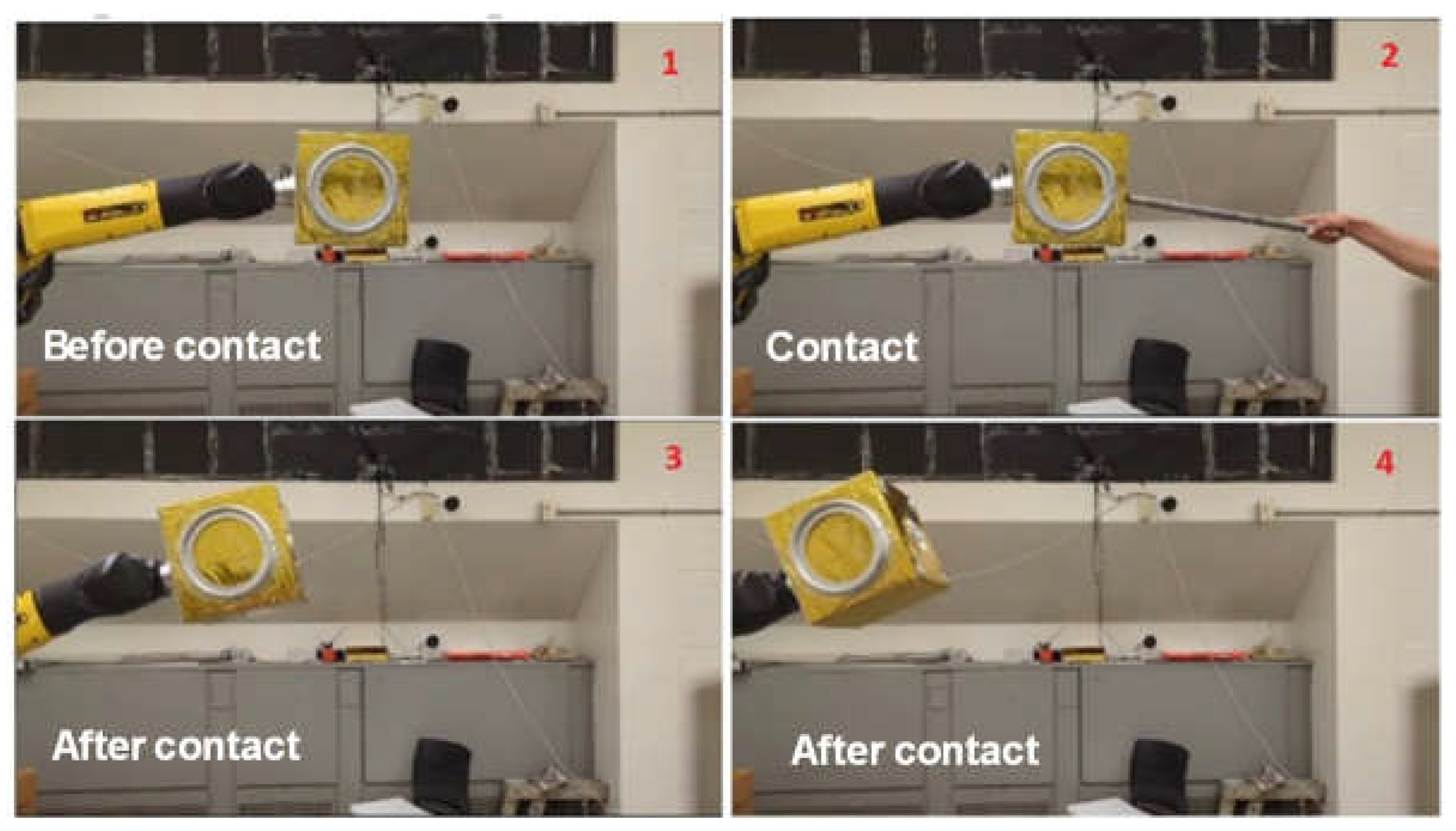
1. Introduction
Space robotic manipulators have become essential components in various space missions, including on-orbit servicing, debris removal, and in-space assembly of large structures, thanks to their high technological readiness level [
1]. They offer distinct advantages over human astronauts by performing tasks that are too time-consuming, risky, and costly for human astronauts [
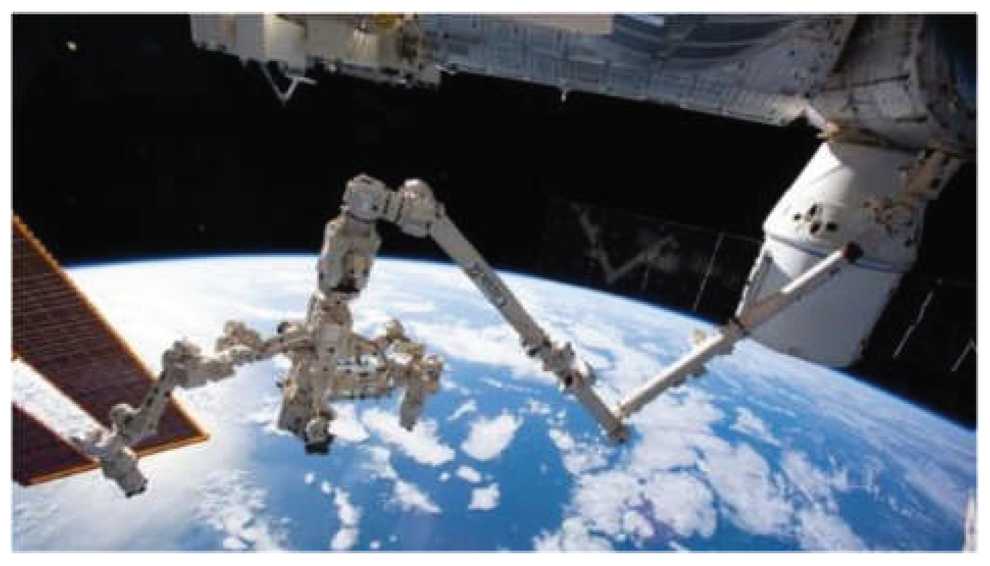
2]. Typically, a space robotic manipulator system comprises a base spacecraft equipped with one or multiple robotic manipulators. A notable example is the Canadarm on the International Space Station (see
Figure 1). 3
The primary challenge in on-orbit service and debris removal missions is the dynamic control problem of a free-floating robot manipulator interacting with a free-floating/tumbling target in microgravity, especially during the capture and post-capture stabilization phases [
1]. Achieving a safe or “soft” capture, where the robot successfully grasps a free-floating malfunctioned spacecraft or non-cooperative debris (hereafter referred to as target) without pushing it away, is critical. Simultaneously, it is essential to stabilize the attitude of the base spacecraft that carries the robot. Once the spacecraft-target combination is safely captured and stabilized, on-orbit service can proceed, or the debris can be relocated to a graveyard orbit or deorbited for re-entry into Earth atmosphere within 25 years [
4]. Given the high-risk nature of these operations, where the robot must physically contact with the target, it is imperative that the capture system and associated control algorithms are rigorously tested and validated on Earth before deployment in space [
5].
Experimental validation for any research is never without difficulties, especially in space applications where access to space for testing is limited and prohibitively expensive. Ground-based testing and validation of a space robot’s dynamic responses and associated control algorithms during contact with an unknown 3D target in microgravity presents additional complexities. Various technologies have been proposed in the literature to mimic microgravity environments on Earth.
The most commonly used method is the air-bearing testbed. For example,
Figure 2(A) and 2(B) show air-bearing testbeds in the authors’ lab at York University [
6] and the Polish Academy of Sciences [
7], respectively. While these testbeds provide an almost frictionless and zero-gravity environment, they are restricted to planar motion and cannot emulate the 6DOF motion of space robots in three-dimensional space.
Another approach involves the use of active suspension systems for gravity compensation [
8] and can achieve 6DOF motion. However, these systems can become unstable due to the coupled vibrations between the space manipulator and suspension system. Additionally, accurately identifying and compensating for kinetic friction within the tension control system remains a significant challenge. Neutral buoyancy, as discussed in Ref. [
9], is another method to simulate microgravity by submerging a space robotic arm in a pool or water tank to test 6DOF motions. However, this method requires custom-built robotic arms to prevent damage from water exposure. Moreover, the effects of fluid damping and added inertia can skew the results, particularly when the system’s dynamic behavior is significant.
The closest approximation to a zero-gravity environment on Earth is achieved through parabolic flight by aircraft [
10] or drop towers [
11]. However, parabolic flights offer a limited microgravity duration of approximately 30 seconds, which is insufficient to fully test the robotic capture process of a target. Furthermore, the cost of these flights is high, and the available testing space in the aircraft cabin is restricted. Drop towers offer even shorter microgravity periods, often less than 10 seconds depending on the tower’s height, with even tight constrained testing space [
11].
The integration of computer simulation and hardware implementation has emerged as a highly effective method for validating space manipulator capture missions. The Hardware-In-the-Loop (HIL) system combines mathematical and mechanical models, utilizing a hardware robotic system to replicate the dynamic behavior of a simulated spacecraft and space manipulator.
Figure 2(C) shows the HIL testbed at the Shenzhen Space Technology Center in China [
12].
Figure 2(D) illustrates the European Proximity Operations Simulator at the German Aerospace Center [
13]. The Canadian Space Agency (CSA) has also developed a sophisticated HIL simulation system - the SPDM (Special Purpose Dexterous Manipulator) Task Verification Facility, shown in
Figure 2(E), which simulates the dynamic behavior of a space robotic manipulator performing maintenance task on the ISS [
14]. This facility is regarded as a formal verification tool.
Figure 2(F) displays the dual-robotic-arm testbed at the Research Institution of Intelligent Control and Testing at Tsinghua University [
17].
Figure 2(G) shows the Manipulator Task Verification Facility (MTVF) developed by the China Academy of Space Technology [
15,
16].
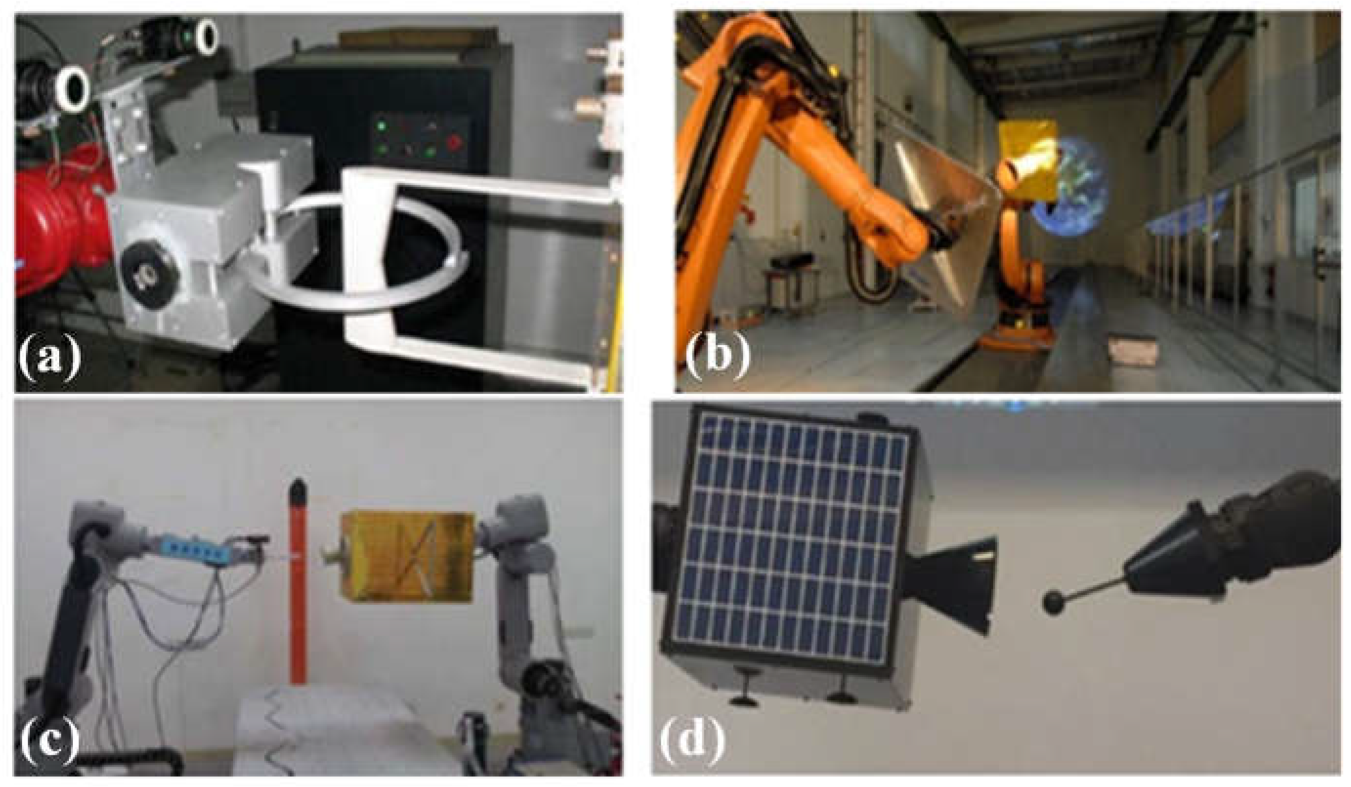
Notably, the existing space robotic testing facilities feature a simple capture interface, which is designed to achieve pose alignment between the robotic end-effector and the target. As summarized in
Figure 3, this basic interface is inadequate for comprehensive capture, sensing feedback, and post-capture stabilization of the target. These tasks require a sophisticated interface, such as a multi-finger gripper integrated with a suite of sensors.
This need motivates the current work to expand the space robotic experimental validation technology by developing a 6DOF HIL space robotic testing facility. This advanced facility incorporates a 3-finger gripper equipped with camera, torque/force sensors and tactile sensors to enable active gravity compensation and precise contact force detection, thereby significantly enhancing the capability for experimental validation in space robotics.
2. Design of Hardware-In-The-Loop Testbed
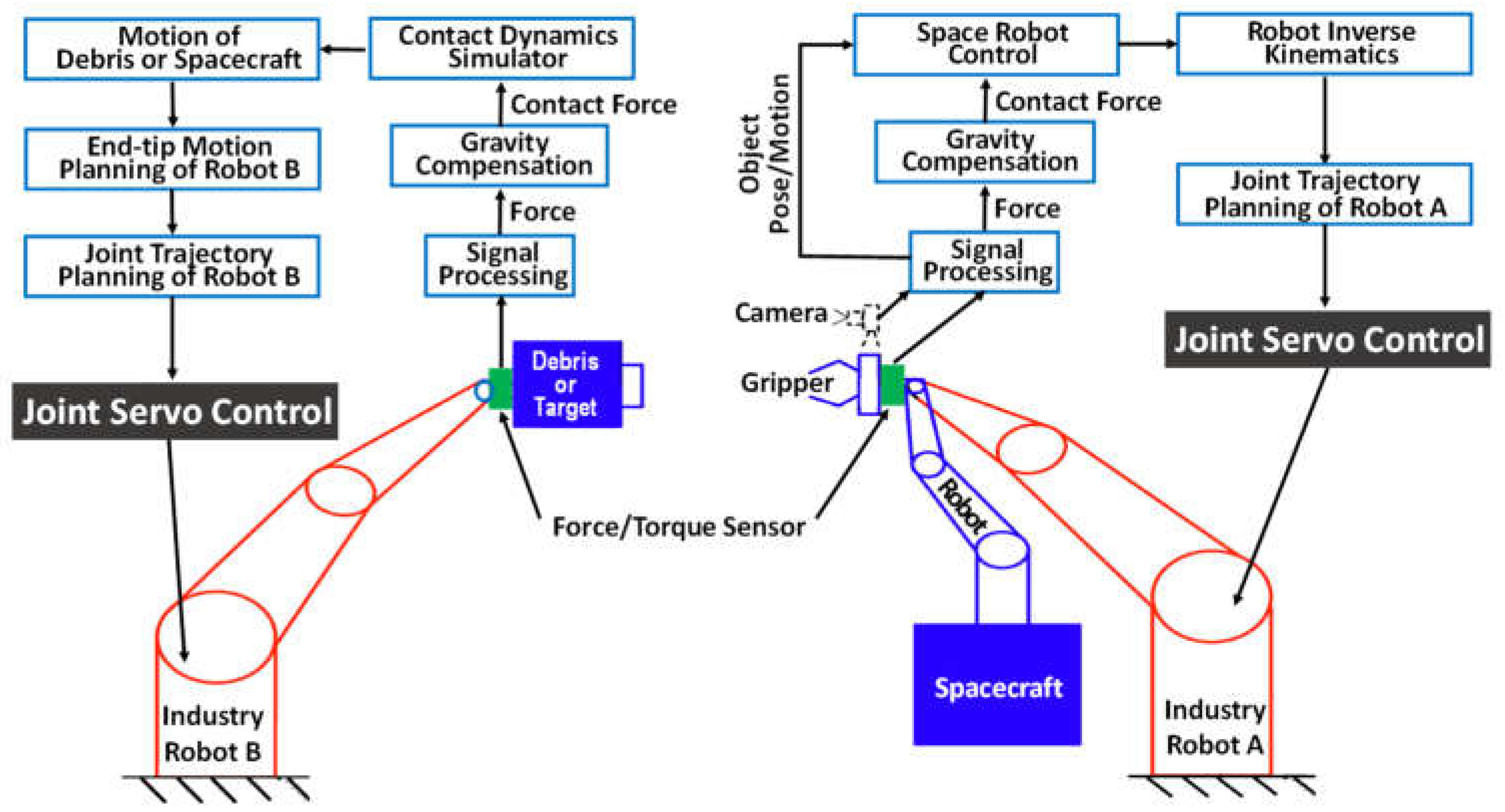
The proposed robotic HIL testbed comprises two key sub-systems, as shown in
Figure 4. The testbed includes two identical 6DOF industrial robots. A mock-up target is affixed to the end-effector of one robot (Robot B), while a robotic finger gripper is mounted to the end-effector of the second robot (Robot A) with a camera in the eye-in-hand configuration. The gripper can autonomously track, approach, and grasp the target, guided by real-time visual feedback from the camera. Two computers are used to simulate the dynamic motion of the free-floating spacecraft-borne robot and the free-floating/tumbling target in a zero-gravity environment based on multibody dynamics and contact models. The 6DOF relative dynamic motions of the space robotic end-effector and the target (depicted as blue components in the figure) are first simulated in 3D space and subsequently converted into control inputs for the robotic arms (represented as red components) to replicate the motions in the physical testbed.
2.1. Robotic Manipulator System
In the HIL configuration, the 6DOF dynamic motions of both the free-floating target and the end effector of the space robotic manipulator (shown in blue in
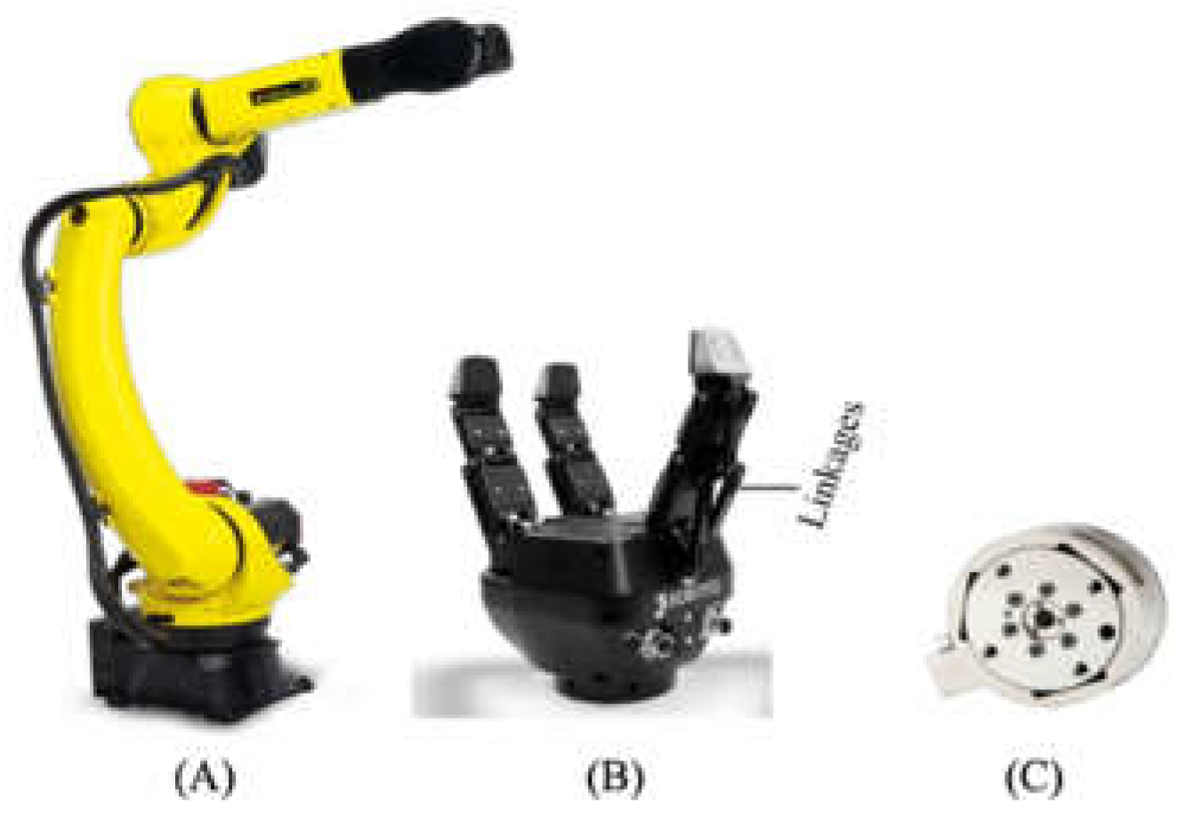
Figure 4) are achieved by two Fanuc M-20iD/25 robotic manipulators [
19], as shown in
Figure 5(A). These robots offer 6DOF motion, enabling precise control of the end effector’s pose (3DOF translational and 3DOF rotational movements). The end effector has a payload capacity of 25 kg and a reach of 1,831mm. Each robotic arm is independently controlled by a dedicated computer.
The robotic arm, identified as a robot (B) in
Figure 4, is equipped with a mock-up target attached to its end effector, and is designed to replicate the target’s free-floating motion in space. An ATI Industries force and torque sensor, shown in
Figure 5(C) and depicted in green
Figure 4, is mounted between the end effector and the mock-up target. This sensor measures both the forces and torques generated by the weight of the mock-up target and any contact forces during a capture event. These measurements, combined with the contact forces measured by the tactile sensors on the gripper, provide a comprehensive assessment of the contact loads on the target. These data are then fed into the dynamic model of the target to simulate its disturbed motion, whether it is in a free-floating state before capture or in a disturbed state after being captured by the gripper. The simulated target motion is subsequently converted into joint commands, which are then fed into the robotic manipulator for execution.
The FANUC industrial robot, designed for high-precision manufacturing environments, is engineered to execute predefined paths with exceptional repeatability (<0.02mm). To enable dynamic path tracking, necessitated by a moving target or gripper, an interface is established between the FANUC robot’s control box and an external computer via an Ethernet connection, utilizing the FANUC StreamMotion protocol. This protocol allows for independent control of the robot’s six joints by streaming joint commands from the external computer, which are written in Python, directly to the FANUC control box. These joint commands must be transmitted and received within a strict timestep of 4-8ms, and the target positions must be within reachable limits. With this interface, the robotic arm (all joints) can be controlled by the simulated path. The robot on the right (Robot A) in
Figure 4 simulates the motion of a free-floating space robotic manipulator in microgravity. This robot is equipped with a gripper from Robotiq, see
Figure 5(B), mounted via an ATI force/load sensor. The gripper features three individually actuated fingers, each consisting of three links. However, only the base link is directly controllable in two directions; the other two links are passively adaptive, designed to conform to varying surface profiles of the target.
Similar to Robot B, Robot A is controlled by an external computer to replicate the gripper’s motion in a microgravity environment. During the capture phase, when contact occurs, the ATI sensor measures the resultant forces and torques, while the tactile sensors on the gripper measure the contact forces. This data provides a detailed assessment of the contact loads on both the target and the robotic manipulator under microgravity conditions, while also accounting for the influence of gravity, enabling active gravity compensation in the simulation program. The contact load data is then processed into the computer simulation algorithms, which generates the appropriate gripper motions as if operating in orbit. Using inverse kinematics, the required joint angle commands for the robotic manipulator are computed and fed into the manipulator’s control box, enabling the gripper to perform precise maneuvers as it would in orbit.
2.2. Capturing Interface
To grasp a moving or potentially tumbling target attached to the robot (B) in
Figure 4, the Robotiq 3-finger adaptive gripper is employed as the capturing interface. The gripper’s specifications are detailed in
Table 1.
The Robotiq 3-finger adaptive gripper is selected for the following compelling reasons:
Flexibility: As an underactuated gripper, the Robotiq 3-finger gripper is capable of adapting to the shape of the target being grasped, providing exceptional flexibility and reliability. This versatility makes it ideal for various applications, from grasping irregularly shaped targets to performing delicate manipulation tasks.
Repeatability: The gripper is capable of providing high repeatability with a precision better than 0.05mm, making it well-suited for tasks requiring precise grasping and manipulation. Some movement is shown in
Figure 6.
Payload Capacity: Capable of handling payloads up to 10 kg, the gripper is suitable for applications involving the manipulation of heavy targets.
Compatibility: The gripper is compatible with most industrial robots and supports control via Ethernet/IP, TCP/IP, or Modbus RTU, facilitating seamless integration with existing robotic systems.
Grasping Modes: The gripper offers four pre-set grasping modes (scissor, wide, pinch, and basic), providing a wide range of grasping setups for grasping different targets.
Grasping Force and Speed: With a maximum grasping force of 60 N and selectable grasping modes, the gripper allows users to choose the most appropriate settings for the specific task, ensuring safe and effective handling of targets of varying shapes and sizes.
Overall, the high level of flexibility, repeatability, and payload capacity of Robotiq gripper make it an ideal choice for current applications.
2.3. Sensing System
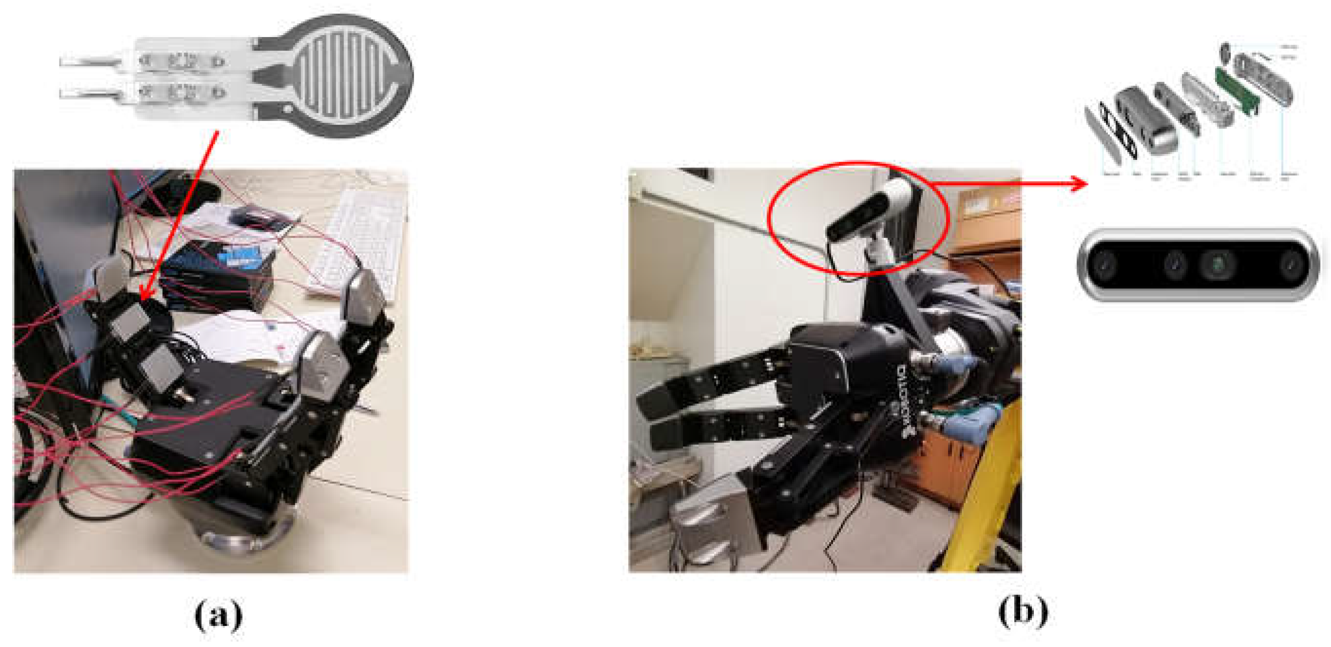
The sensing system in the HIL testbed includes two ATI force/torque sensors, custom tactile sensors (
Figure 7(A)) mounted on each link of the gripper’s fingers, and an Intel® RealSense™ depth camera D455 (
Figure 7(B)). The tactile sensors, constructed from thin-film piezoresistive pressure sensors, are affixed to the finger links of the gripper. These sensors measure normal contact forces between the gripper and the target, ensuring the safety of both components. To improve the accuracy of sensor data, they are integrated into 3D-printed plastic adaptors that adapt to the contours of the fingers. These adaptors maintain consistent contact and ensure that forces exerted on the gripper’s fingers are accurately recorded and fed back into the control loop. This feedback is instrumental in controlling the fingers with greater precision and improving the gripper’s ability to grasp the target securely.
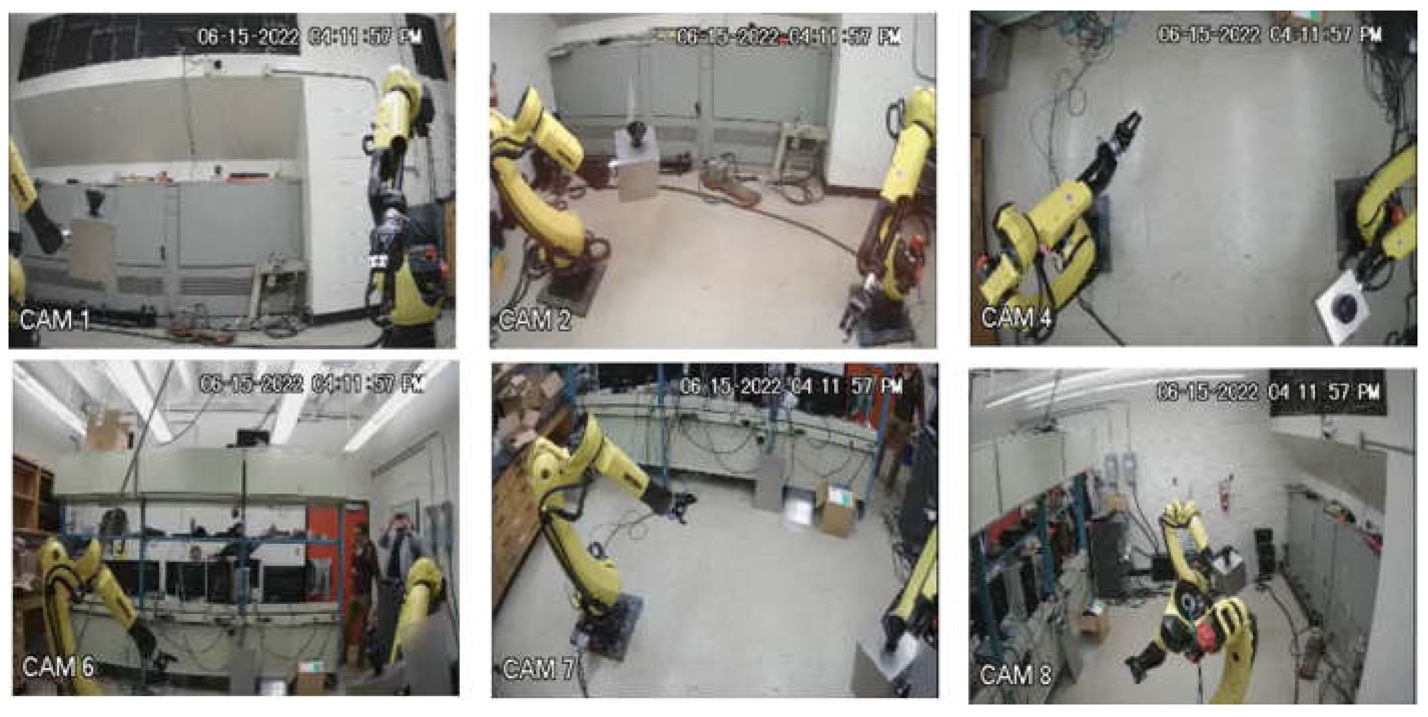
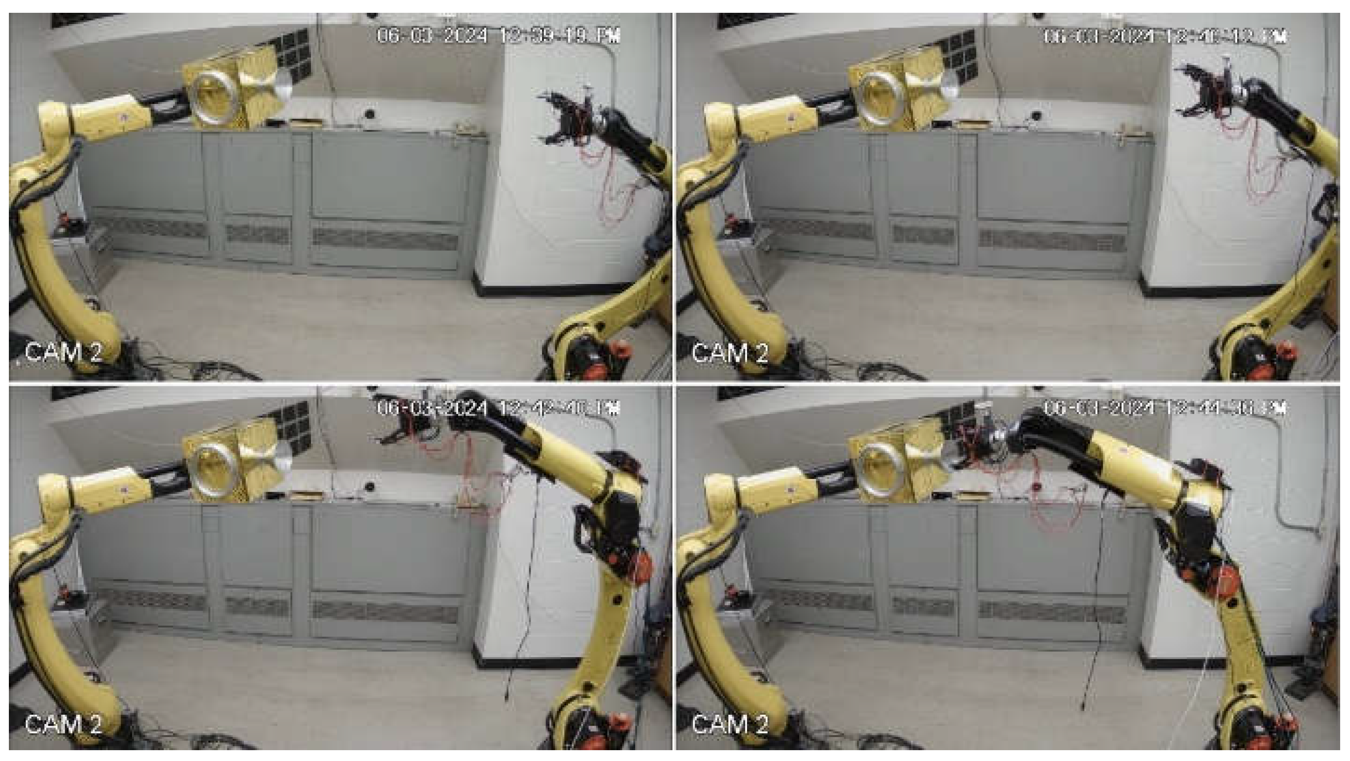
The Intel RealSense camera determines the target’s relative pose by either photogrammetry or AI-enhanced computer vision algorithms. This information is fed into the robotic control algorithm, which guides the robot to autonomously track and grasp the target. Furthermore, six high-resolution (2K) TV cameras are strategically positioned in the testing room to monitor the test from six angles to provide ground truth data, see
Figure 8.
2.4. Mock-Up Target Satellite
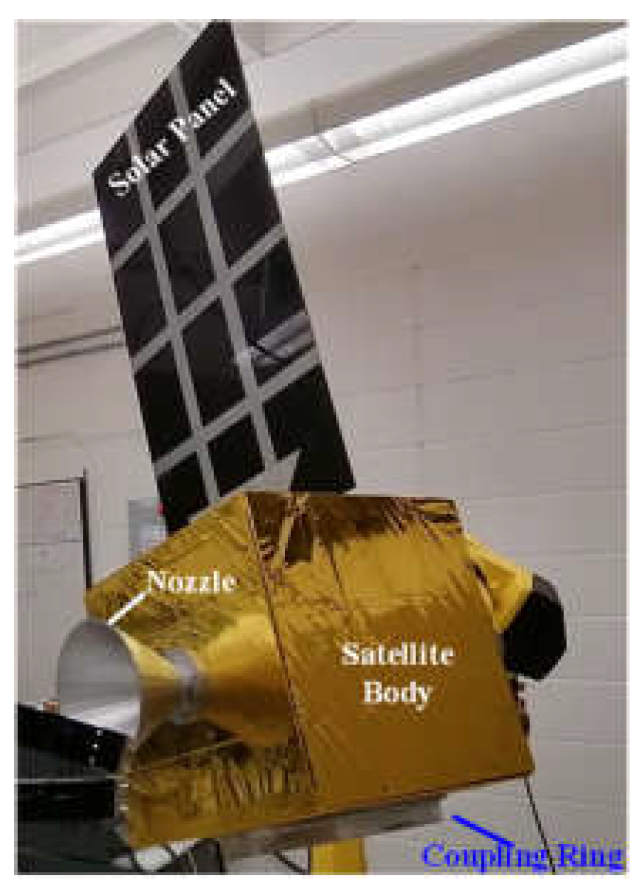
The mock-up target used in this testbed is a scale-down model of a typical satellite. It is a 30 cm cube made of 1/8-inch-thick aluminum plates, directly bolted to the ATI force/torque sensor, which is subsequently mounted to the end effector of the robotic manipulator. To mimic the appearance of a real satellite for training of AI-computer vision algorithm, the cube is wrapped in thermal blankets that replicate the light-reflective properties of real satellites in space.
Additional components, including a dummy thrust nozzle, coupling ring, and solar panel, are attached to the mock satellite, as shown in
Figure 9. The illumination condition in the testing room is adjustable to simulate a space-like environment, such as using a single light source to mimic the sunlight. This setup is designed to train AI-enhanced computer vision algorithm to accurately recognize the target’s pose in a simulated space environment.
2.5. Computer System
Two desktop PCs are employed to control a pair of FANUC robotic manipulators. The first PC controls the robot interacting with the mock-up target. This computer executes open-loop forward control to move the mock-up target as if it is in orbit. During a capture event, the resultant contact forces, after compensating for gravity, are input into the simulation program to calculate the target’s disturbed motion in real time. The motion is then converted into robotic joint angle commands by inverse kinematics, which are transmitted to the robot’s control box to emulate the target as if it would in a microgravity environment. This task does not require high computing power. Hence, a Dell XPS 8940 desktop PC was employed.
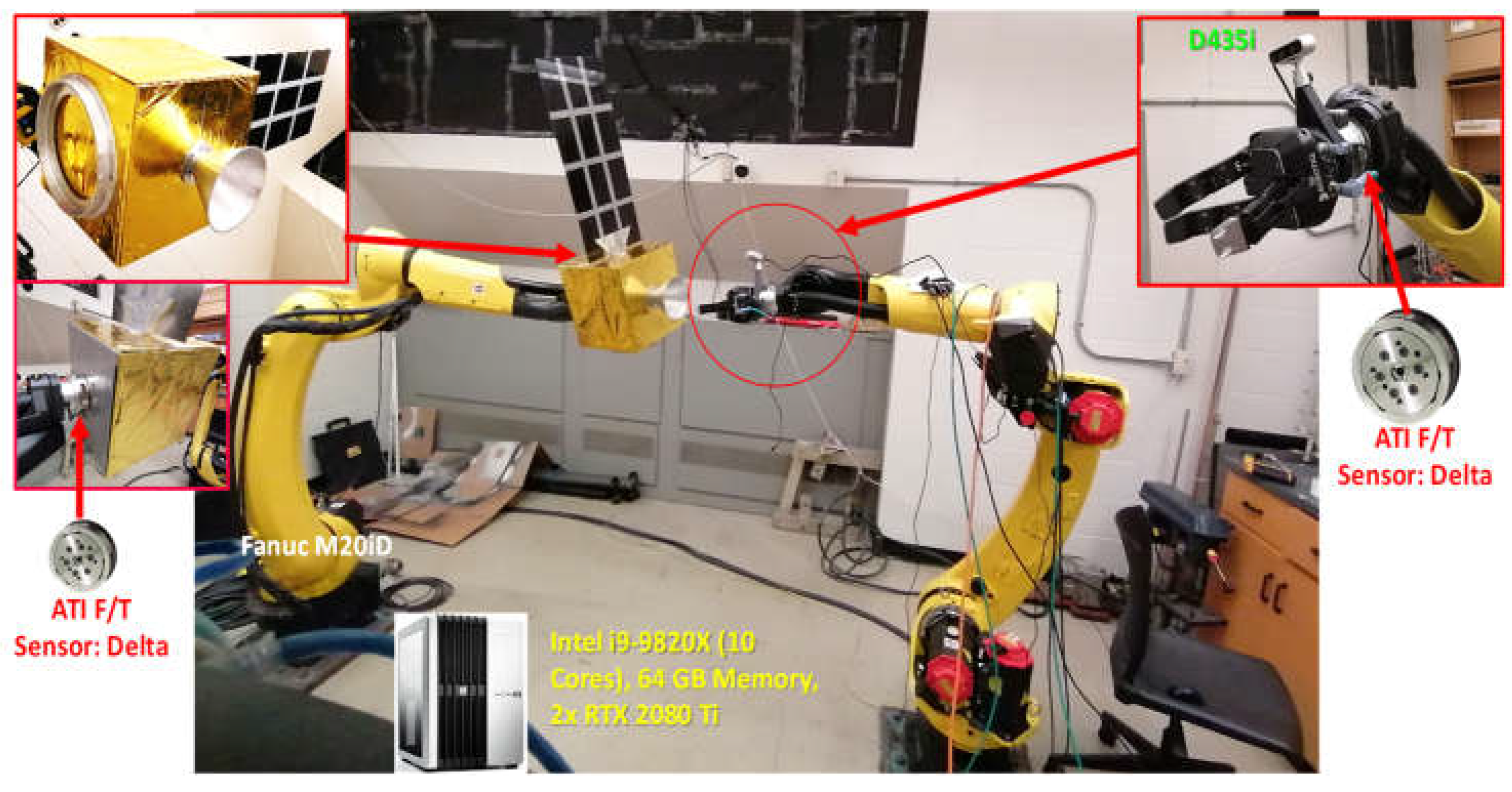
The second PC is responsible for collecting measurement data from camera, tactile sensors, and force/torque sensors, simulating the 6DOF motion of the space robot, and then controlling the robotic manipulator and gripper to replicate the gripper’s motion in a microgravity environment. In case of a capture event, the computer controls the robotic manipulator and gripper to synchronize the motion of the gripper with the target. This process demands high computing power and, accordingly, a Lambda™ GPU Desktop PC - Deep Learning Workstation was selected for this purpose. The integrated HIL testbed is shown in
Figure 10.
3. Preliminary Experimental Results
This section details some preliminary experimental results conducted for each subsystem of the HIL testbed.
3.1. Multiple Angle Camera Fusion
Preliminary tests were conducted to establish ground truth data for capture validation using six TV cameras. As shown in
Figure 8, the motions of two robotic manipulators were recorded from six different angles, enabling comprehensive monitoring of the tracking, capture, and post-capture stabilization control.
3.2. Computer Vision
The AI-based YOLO V5 [
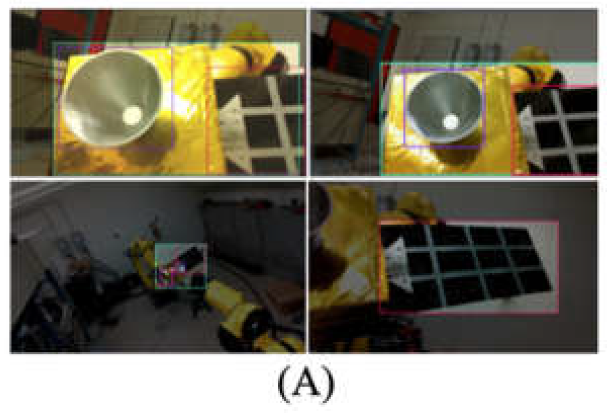
20] is employed to recognize the interested features and then track the relative pose and motion of the target using the Intel depth camera input as shown in
Figure 7(B). First, the algorithm is trained to identify the target by bounding key features (e.g., nozzle, coupling ring, solar panel) at different viewing angles and distances and different illumination conditions, as illustrated in
Figure 11(A). Next, the algorithm is trained to estimate the target’s pose by analyzing these features.
To validate the vision system, a camera is positioned above the gripper in an eye-in-hand configuration, as shown in
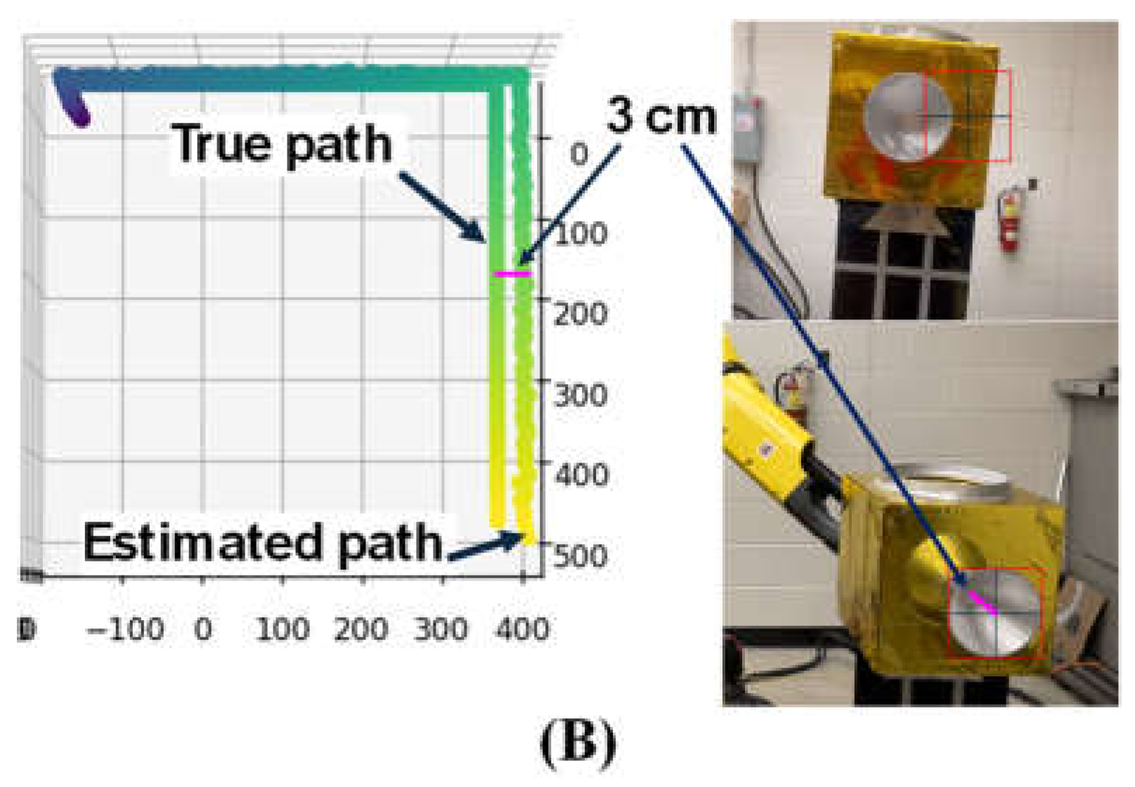
Figure 10. The target was then moved 0.5 m away from the camera along camera’s optical axis, 0.5 m downward, and 0.5 m sideways. During this movement, the computer vision system continuously estimated and recorded the target’s pose in real time. In this case, it is noted that there was no rotational movement of the target.
The target’s true position was determined by the FANUC robot control system with an accuracy of 0.02mm.
Figure 11(B) shows a comparison between the target’s position as determined by the FANUC robot and the YOLO algorithm. The results indicate that the position error is minimal when the target is moved away along the camera’s optical axis. However, as the target moves away from the camera’s optical axis, the error increases to 3cm, representing approximately 6% of the displacement. This error arises because the nozzle appears skewed in the camera’s view, causing the center of the bounding box (representing the nozzle’s position estimated by YOLO) to deviate from the actual nozzle center, see the magenta line in
Figure 11(B). Currently, the YOLO algorithm does not address this issue, highlighting the need for future research to minimize such errors.
3.3. Kinematic Equivalence
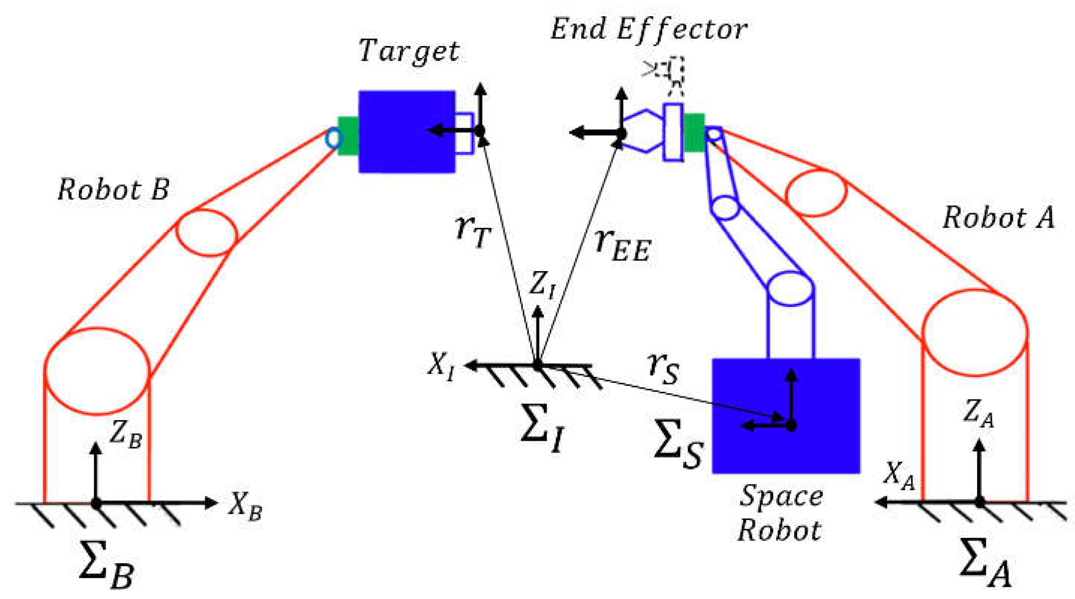
The simulated dynamic motions of the space manipulator end-effector and the target are replicated by FANUC robots. This kinematic equivalence concept is shown in
Figure 12 and described as follows.
In this kinematic equivalence, the base frames of the industrial robots A (
) and B (
) are fixed to the ground with respect to the inertial frame (
), while the base frame of the space manipulator (
) is free-floating with respect to the inertial frame (
). The space manipulator’s motion is achieved by industrial robot A, and the target’s motion is replicated by robot B. Once the path of the space manipulator’s gripper pose is generated in computer simulation, the gripper’s pose relative to the frame (
) is calculated in Eq. (1).
Then, the desired joint angles for industrial robot A are calculated using its inverse kinematic equation, see in Eq. (2),
where
is the direct kinematic equation of robot A, calculated using the DH parameters of the Fanuc M-20iD/25 robotic manipulators 19 as shown in
Table 2.
For the Target, its path is calculated in the frame (
) in simulation. The simulated path is achieved by the industrial robot B using Eq. (3)
Finally, the desired joint angles for the industrial robot B are calculated by its inverse kinematic equation, as seen in Eq. (4)
where
is the direct kinematic equation of the robot B, calculated similar to the robot A.
3.4. Target Motion
The target motion simulation is determined based on the tumbling rate of the GOES 8 geostationary satellite (Ref. [
21]) and Envisat (Ref. [
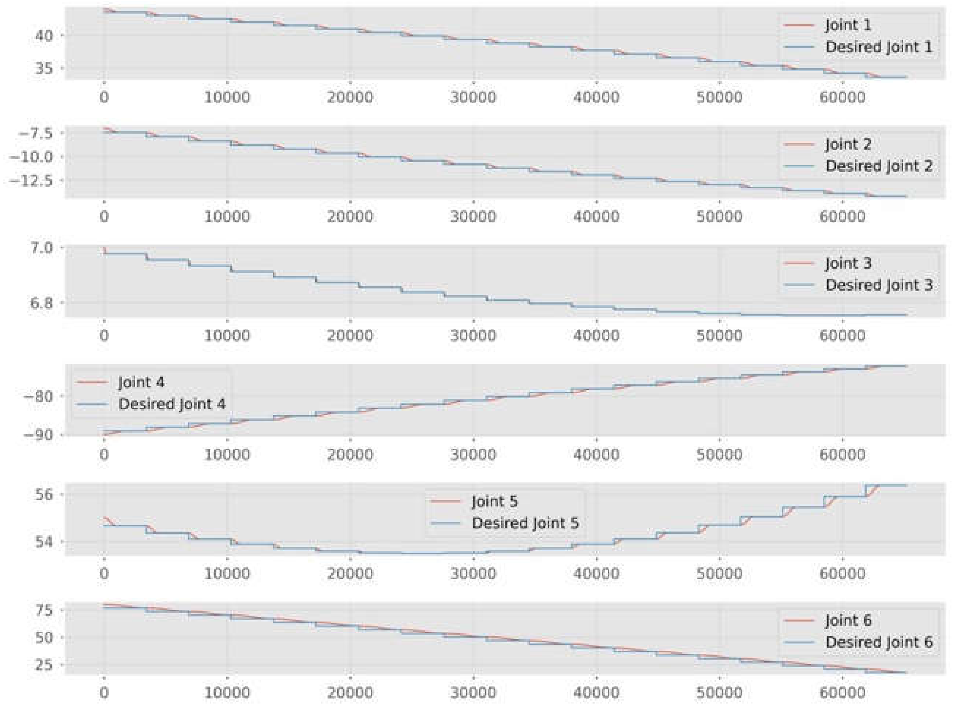
22]). Specifically, a drift rate of -0.01 m/s in the x-axis direction and a tumbling rate of 0.28, 2.8, and 0.28 deg/s about the roll, pitch, and yaw axis in the frame of, respectively, are used to model the target’s motion. This motion is then converted into joint angle commends by the inverse kinematics of the robot B.
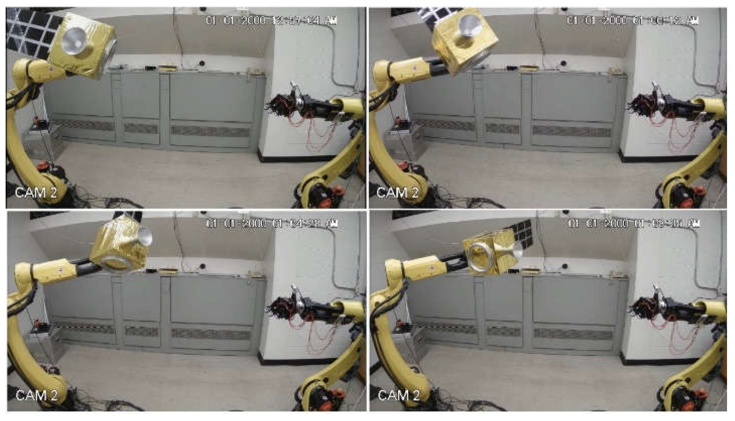
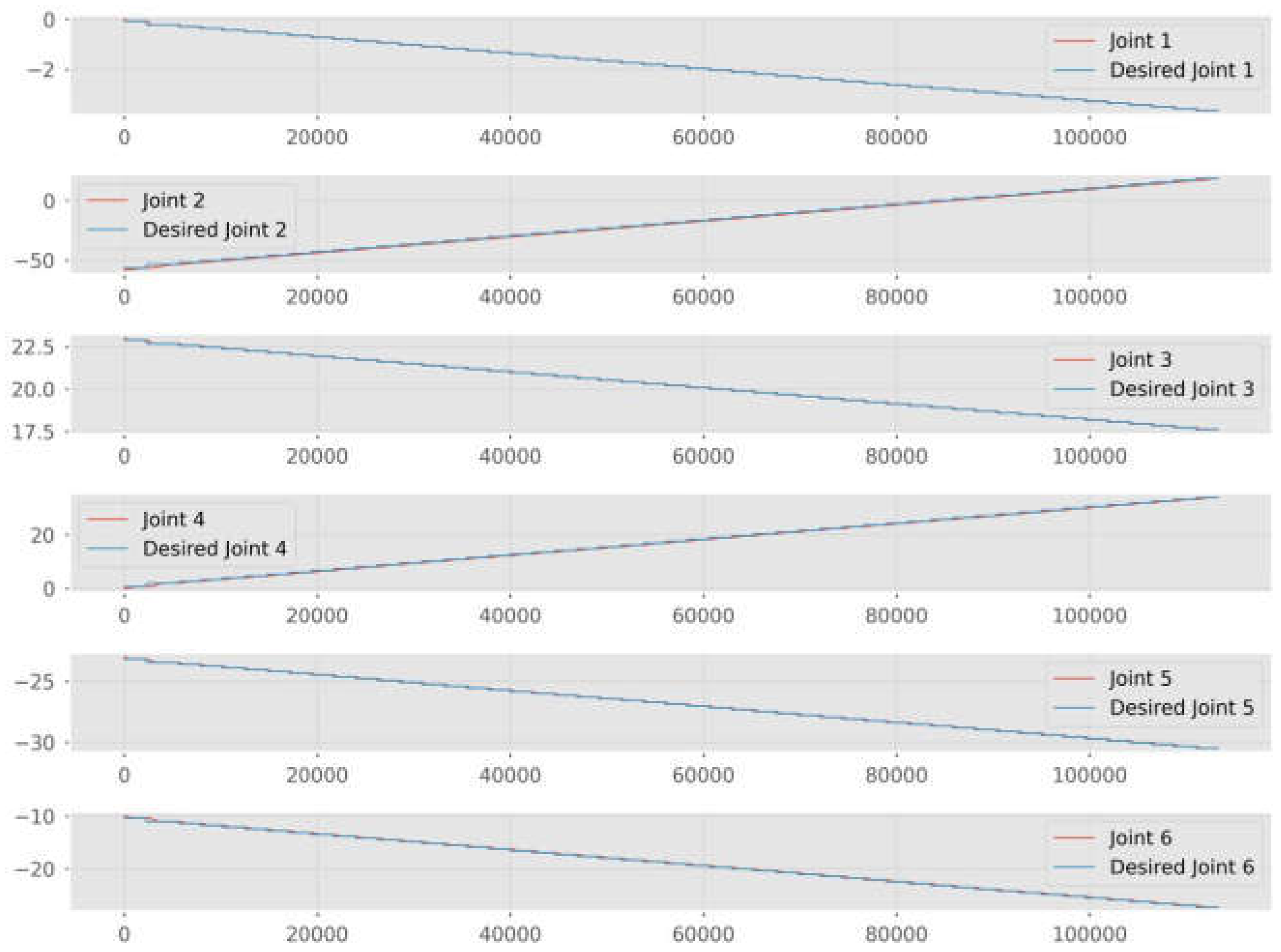
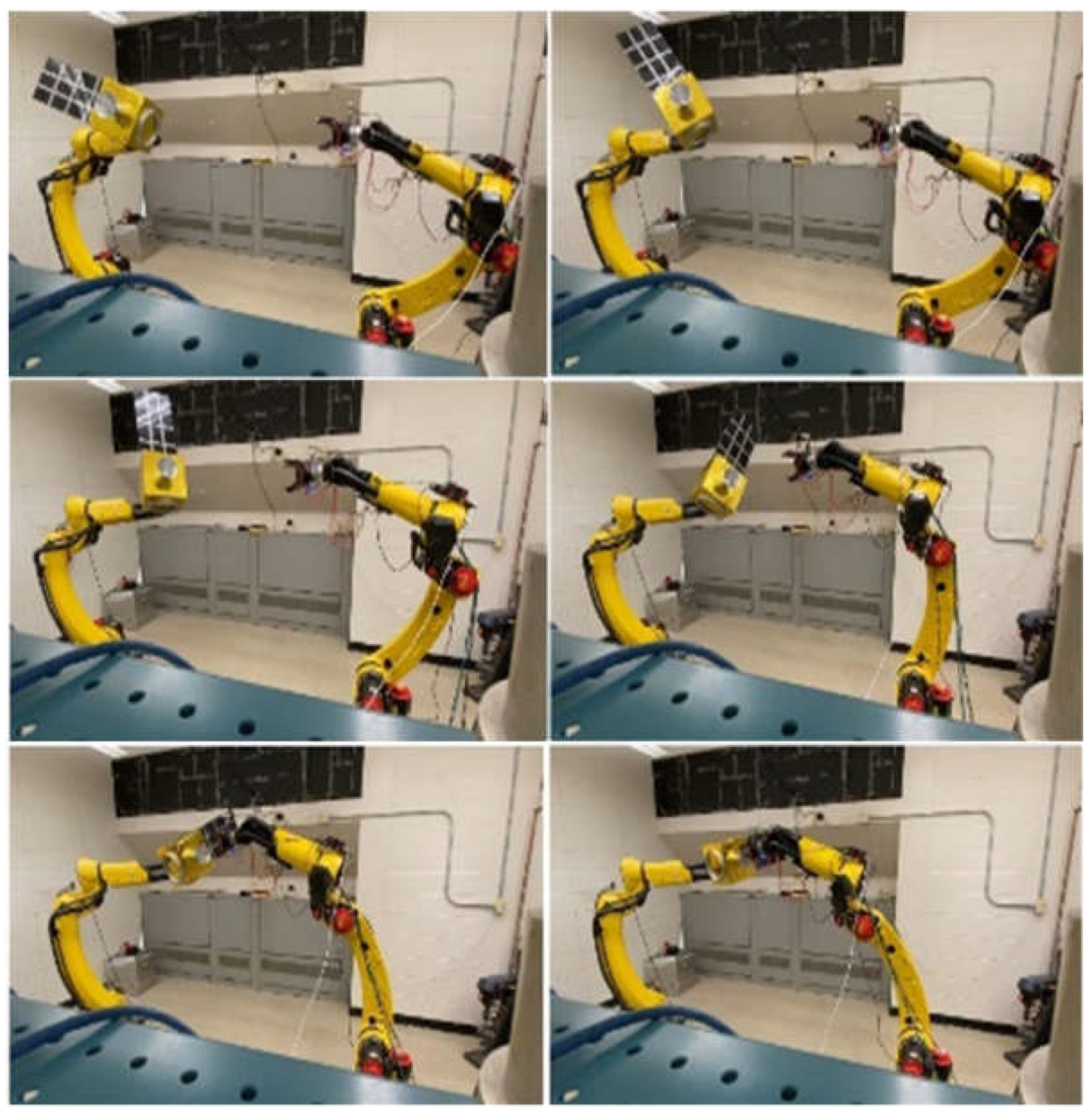
Figure 13 shows the desired joint commands fed into the robotic control box and the actual joint positions achieved by the robot at each time step. The target successfully replicates the behavior of tumbling space debris. Snapshots of the target motion are shown in
Figure 14.
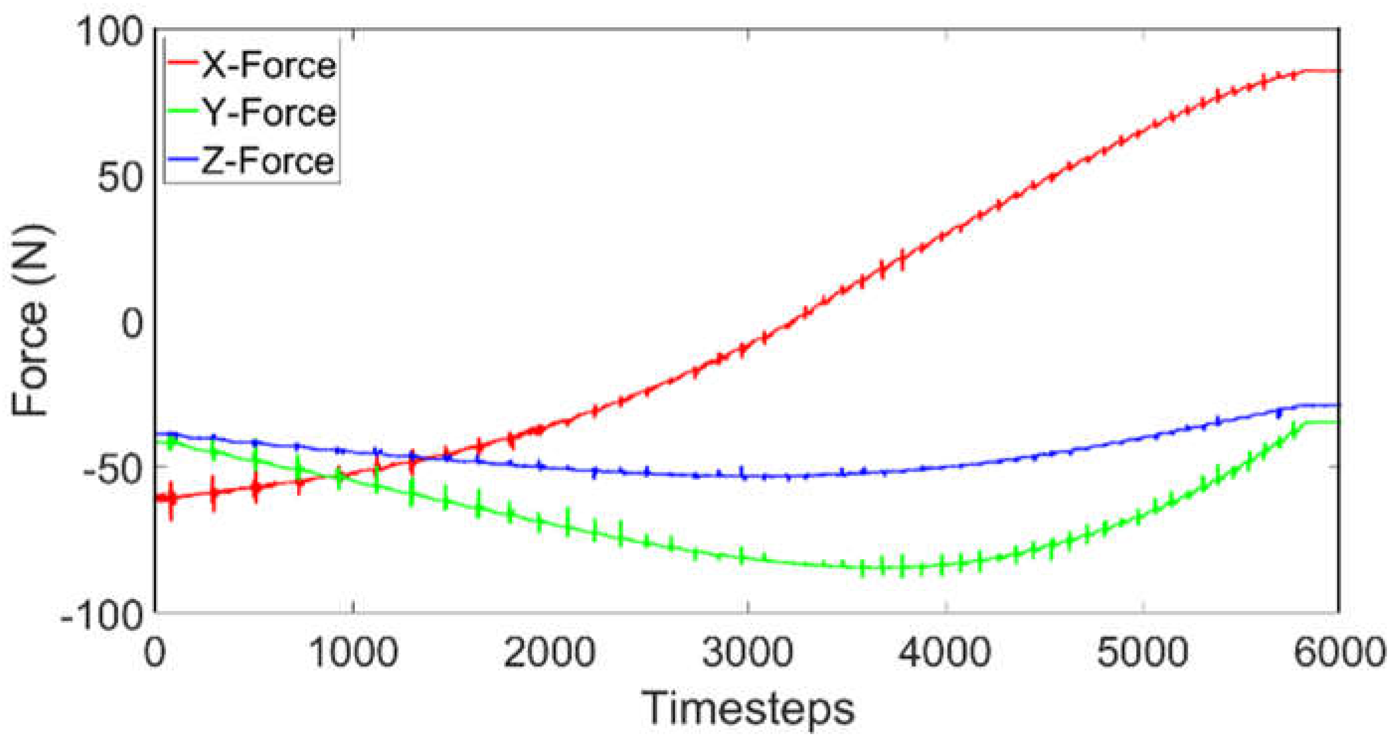
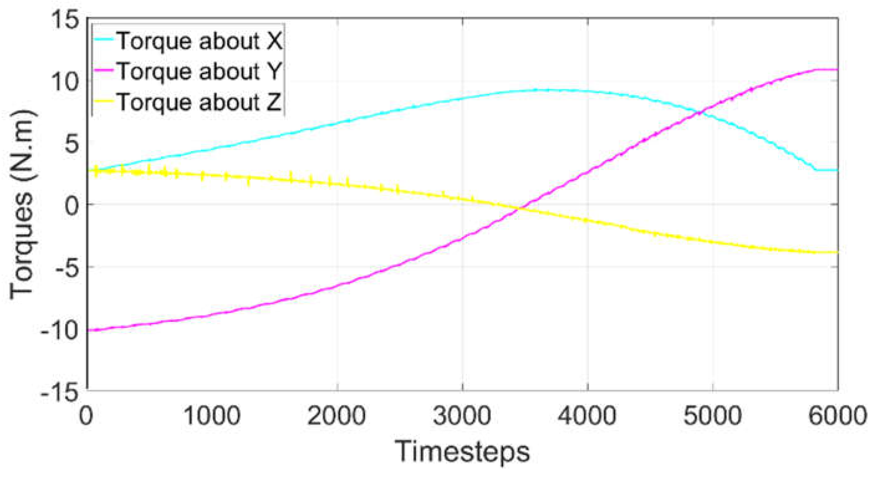
Forces and torques measured by the ATI force/load sensor are recorded during the tumbling motion of the target.
Figure 15 illustrates the measured forces in the x, y, and z directions, while
Figure 16 presents the measured torques about the x, y, and z axes. These measurement data will serve as a baseline to account for the gravitational effects and will be used to extract the true contact force if contact with the gripper occurs. Details about the software-in-the-loop active gravity compensation will be given in Section III.F.
3.5. Pre-Grasping Gripper Motion
After the computer vision system retrieves the target’s pose relative to the gripper, the gripper’s path is planned based on the capture criteria and then converted into joint angle commands for robot A, which maneuvers the gripper toward the target.
Figure 17 shows desired joint commands, derived from kinematic equivalence, which are input into the robot A to achieve the capture, alongside the actual joint positions achieved by the robot A at each time step. Snapshots of this motion are shown in
Figure 18.
The gripper is guided by the computer vision system, which obtains the relative pose of the target’s capture feature (in this case, a nozzle) during the approach phase. The complete simultaneous capture motion is shown in
Figure 19.
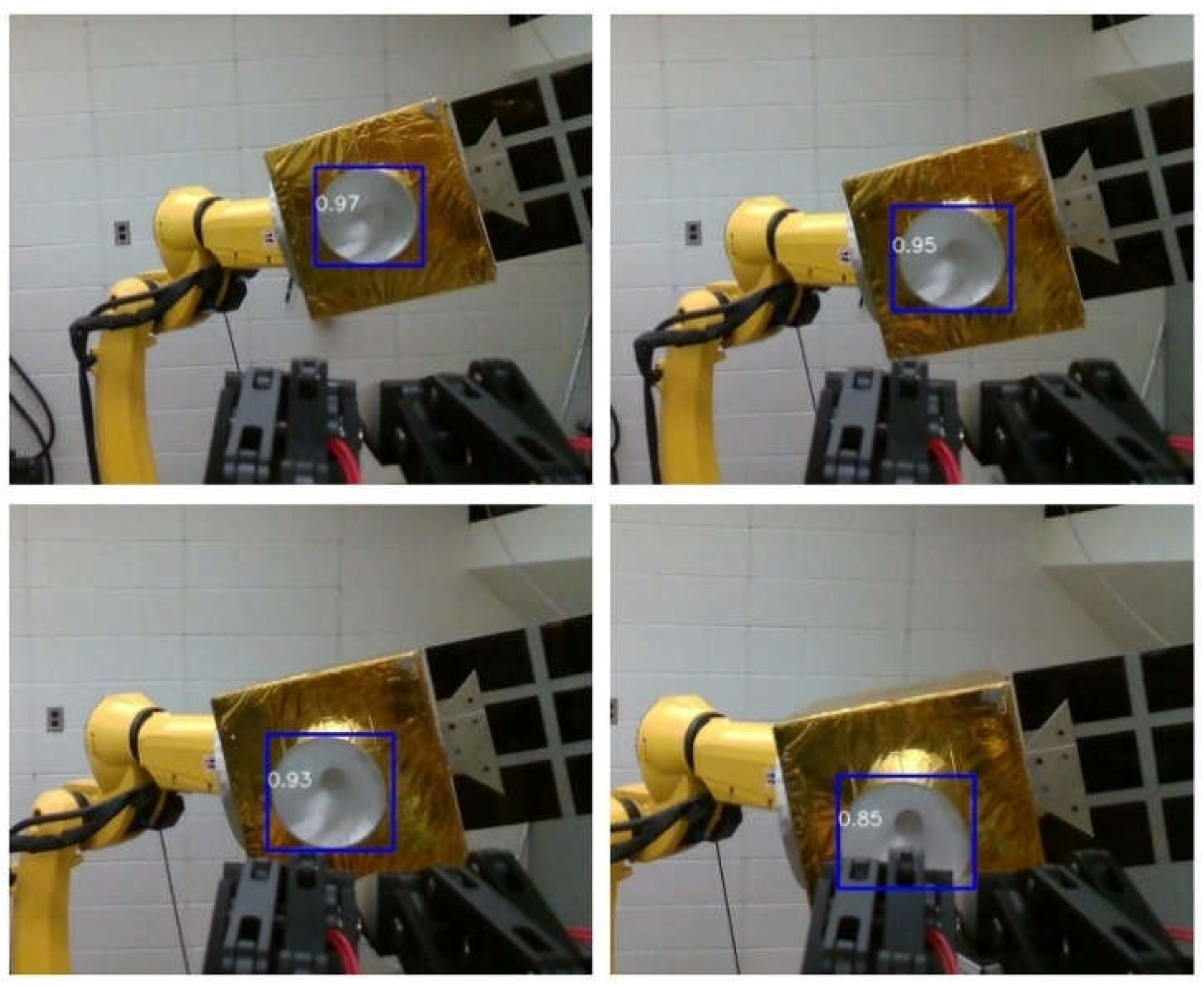
As the gripper approaches the target, the capture feature may move out of the camera’s field of view or be blocked by the gripper in the close proximity, see
Figure 20. Currently, the controller relies on the last known pose estimate and continues moving toward that pose. Future work will involve integrating additional eye-to-hand cameras, as shown in
Figure 8, in addition to the eye-in-hand camera, to maintain continuous target tracking by the computer vision.
3.6. Active Gravity Compensation
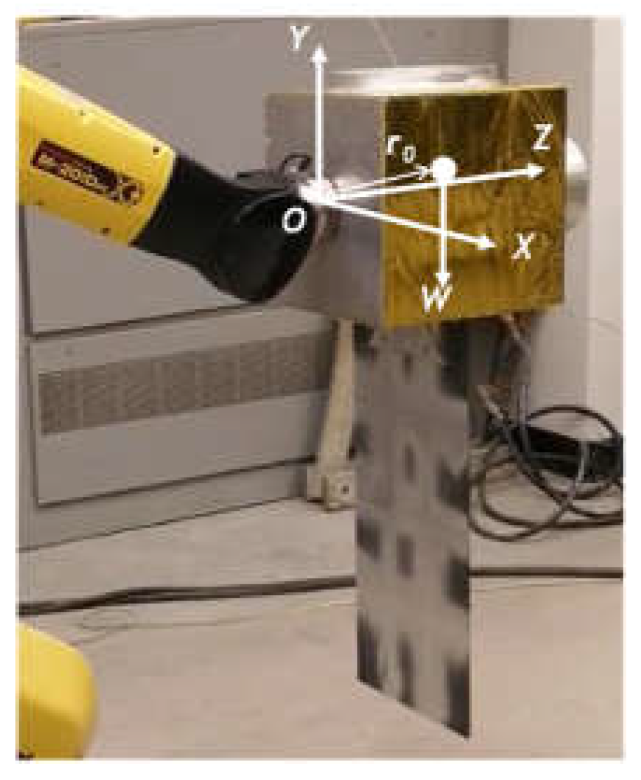
Active gravity compensation is achieved by the ATI force/torque sensor mounted between the end effector of robot B and the target. Prior to contact with the gripper, the sensor measures the force and moment exerted by gravity as follows:
where
T is the transformation matrix from the inertial frame to the local frame fixed to the sensor,
W is the target’s weight vector in the inertial frame and
is the position vector of the target’s center of gravity in the sensor’s local frame. Both
W and
are known from the design of the target, while the transformation matrix
T is determined by the kinematics of the robot B based on the joint angle measurement from the robotic control system.
Upon contact between the target and the gripper, the force and moment measured by the ATI sensor are changed to:
where
Fc is the true contact force acting on the target and the
r is the location of the contact point, which can be determined by the computer vision.
From Eqs. (7)-(8), the contact force
Fc and moment
Mc acting at the center of mass of the free-floating target are calculated as:
Finally, Fc and Mc are input into the dynamic model of the target to calculate the motion caused by the contact disturbance. This disturbed motion is then mapped into the robotic joint angle commands, allowing the robot B holding the target to mimic the motion of the target. Snapshots of the target’s motion with gravity compensation are shown in Error! Reference source not found..
Figure 22.
The target’s free-floating motion disturbed by an external force.
Figure 22.
The target’s free-floating motion disturbed by an external force.
4. Conclusion
This study includes the development of a hardware-in-the-loop ground testbed featuring active gravity compensation via software-in-the-loop integration, specially designed to support research in autonomous robotic removal of space debris. Some preliminary results of experiments are presented to show it ability in computer vision, path planning, torque/force sensing, and active gravity compensation via software-in-the-loop to achieve a full zero-gravity emulated target capture mission on Earth.
Author Contributions
Conceptualization, A.A., B.H. and Z.H.Z.; methodology, A.A., B.H. and Z.H.Z.; investigation, A.A., B.H; resources, Z.H.Z; writing—original draft preparation, A.A., B.H. and Z.H.Z.; writing—review and editing, Z.H.Z.; visualization, A.A., B.H.; supervision, Z.H.Z.; project administration, Z.H.Z.; funding acquisition, Z.H.Z. All authors have read and agreed to the published version of the manuscript.
Funding
This research was funded by the Canadian Space Agency, Flights and Fieldwork for the Advancement of Science and Technology grant number 19FAYORA14, and by the Natural Sciences and Engineering Research Council of Canada, Discovery Grant number RGPIN-2024-06290 and Collaborative Research and Training Experience Program Grant number 555425-2021.
Data Availability Statement
The raw data supporting the conclusions of this article will be made available by the authors on request.
Conflicts of Interest
The authors declare no conflicts of interest.
References
- F.-A. Angel, O. Ma, K. Pham, S. Ulrich, “A review of space robotics technologies for on-orbit servicing,” Progress in Aerospace Sciences, vol. 68 pp, 1-26, 2014. [CrossRef]
- B.P. Larouche, Z. H. Zhu, “Autonomous robotic capture of the non-cooperative target using visual servoing and motion predictive control,” Autonomous Robots, vol. 37, no. 2, pp. 157-167, Jan. 2014. [CrossRef]
-
https://www.asc-csa.gc.ca/eng/blog/2021/04/16/canadarm2-celebrates-20-years-on-international-space-station.asp, visited on June 9, 2023.
- Kessler, Donald J., Nicholas L. Johnson, J. C. Liou, and Mark Matney. “The Kessler syndrome: implications to future space operations.” Advances in the Astronautical Sciences 137, no. 8 (2010): 2010.
- Yang, F., Z. H. Dong, and X. Ye. “Research on Equivalent Tests of Dynamics of On-orbit Soft Contact Technology Based on On-Orbit Experiment Data.” In Journal of Physics: Conference Series, vol. 1016, no. 1, p. 012013. IOP Publishing, 2018. [CrossRef]
- Santaguida, Lucas, and Zheng H. Zhu. “Development of air-bearing microgravity testbed for autonomous spacecraft rendezvous and robotic capture control of a free-floating target.” Acta Astronautica 203 (2023): 319-328. [CrossRef]
- Rybus, Tomasz. “Obstacle avoidance in space robotics: Review of major challenges and proposed solutions.” Progress in Aerospace Sciences 101 (2018): 31-48. [CrossRef]
- S Jia, Jiao, Yingmin Jia, and Shihao Sun. “Preliminary design and development of an active suspension gravity compensation system for ground verification.” Mechanism and Machine Theory 128 (2018): 492-507. [CrossRef]
- Carignan, Craig R., and David L. Akin. “The reaction stabilization of on-orbit robots.” IEEE Control Systems Magazine 20, no. 6 (2000): 19-33. [CrossRef]
- Zhu, Zheng H., Junjie Kang, and Udai Bindra. “Validation of CubeSat tether deployment system by ground and parabolic flight testing.” Acta Astronautica 185 (2021): 299-307. [CrossRef]
- Xu, Wenfu, Bin Liang, and Yangsheng Xu. “Survey of modeling, planning, and ground verification of space robotic systems.” Acta Astronautica 68, no. 11-12 (2011): 1629-1649. [CrossRef]
- Xu, Wenfu, Bin Liang, Yangsheng Xu, Cheng Li, and Wenyi Qiang. “A ground experiment system of free-floating robot for capturing space target.” Journal of intelligent and robotic systems 48 (2007): 187-208. [CrossRef]
- Boge, Toralf, and Ou Ma. “Using advanced industrial robotics for spacecraft rendezvous and docking simulation.” In 2011 IEEE international conference on robotics and automation, pp. 1-4. IEEE, 2011. [CrossRef]
- Rekleitis, Ioannis, Eric Martin, Guy Rouleau, Régent L’Archevêque, Kourosh Parsa, and Eric Dupuis. “Autonomous capture of a tumbling satellite.” Journal of Field Robotics 24, no. 4 (2007): 275-296. [CrossRef]
- Liu, Qian, Xuan Xiao, Fangli Mou, Shuang Wu, Wei Ma, and Chengwei Hu. “Study on a Numerical Simulation of a Manipulator Task Verification Facility System.” In 2018 IEEE International Conference on Mechatronics and Automation (ICMA), pp. 2132-2137. IEEE, 2018. [CrossRef]
- Mou, Fangli, Xuan Xiao, Tao Zhang, Qian Liu, Daming Li, Chengwei Hu, and Wei Ma. “A HIL simulation facility for task verification of the chinese space station manipulator.” In 2018 IEEE International Conference on Mechatronics and Automation (ICMA), pp. 2138-2144. IEEE, 2018. [CrossRef]
- Liu, Houde, Bin Liang, Xueqian Wang, and Bo Zhang. “Autonomous path planning and experiment study of free-floating space robot for spinning satellite capturing.” In 2014 13th International Conference on Control Automation Robotics & Vision (ICARCV), pp. 1573-1580. IEEE, 2014. [CrossRef]
- J. Luo, M. Yu, M. Wang, J. Yuan, “A Fast Trajectory Planning Framework with Task-Priority for Space Robot,” Acta Astronautica, vol. 152, pp. 823-835, 2018. [CrossRef]
-
https://www.fanucamerica.com/products/robots/series/m-20/m-20id-25. Visited on July 24, 2023.
- Jocher, G. (2020). YOLOv5 by Ultralytics (Version 7.0) [Computer software]. [CrossRef]
- Cognion, Rita L. “Rotation rates of inactive satellites near geosynchronous earth orbit.” In Proceedings of the Advanced Maui Optical and Space Surveillance Technologies Conference. Kihei, HI: Maui Economic Development Board, 2014.
- Kucharski, Daniel, Georg Kirchner, Franz Koidl, Cunbo Fan, Randall Carman, Christopher Moore, Andriy Dmytrotsa et al. “Attitude and spin period of space debris Envisat measured by satellite laser ranging.” IEEE Transactions on Geoscience and Remote Sensing 52, no. 12 (2014): 7651-7657. [CrossRef]
- Beigomi, B. (2023). robotiq3f_py (Version 2.0.0) [Computer software]. [CrossRef]
Figure 1.
Space robotic manipulator – Canadarm [
3].
Figure 1.
Space robotic manipulator – Canadarm [
3].
Figure 2.
(A) Air-bearing testbed at York University [
6], (B) Air-bearing testbed at Polish Academy of Sciences [
7], (C) HIL testbed at Shenzhen Space Technology Center [
12], (D) European proximity operations simulator at German Aerospace Center [
13], (E) CSA SPDM task verification facility [
14], (F) Dual robotic testbed at Tsinghua University[
15,
17], (G) MTVF at China Academy of Space Technology [
15].
Figure 3.
(a) Shenzhen Space Technology Center [
12], (b) German Aerospace Center [
13], (c) China Academy of Space Technology [
17]. (d) Tsinghua University [
15].
Figure 3.
(a) Shenzhen Space Technology Center [
12], (b) German Aerospace Center [
13], (c) China Academy of Space Technology [
17]. (d) Tsinghua University [
15].
Figure 4.
Schematic of Dual-robot HIL Testbed.
Figure 4.
Schematic of Dual-robot HIL Testbed.
Figure 5.
(A) Fanuc manipulator, (B) Robotiq gripper, (C) ATI force/load sensor.
Figure 5.
(A) Fanuc manipulator, (B) Robotiq gripper, (C) ATI force/load sensor.
Figure 6.
Robotiq 3-Finger Gripper Movement.
Figure 6.
Robotiq 3-Finger Gripper Movement.
Figure 7.
(A) Tactile sensor, (B) Intel Camera.
Figure 7.
(A) Tactile sensor, (B) Intel Camera.
Figure 8.
Full-scale monitoring of all angles.
Figure 8.
Full-scale monitoring of all angles.
Figure 9.
Mock-up Satellite and Components.
Figure 9.
Mock-up Satellite and Components.
Figure 10.
6DOF hardware-in-the-loop ground testbed.
Figure 10.
6DOF hardware-in-the-loop ground testbed.
Figure 11.
Training of AI computer vision for target tracking.
Figure 11.
Training of AI computer vision for target tracking.
Figure 12.
Kinematic Equivalence.
Figure 12.
Kinematic Equivalence.
Figure 13.
Joint motions of robot B to deliver the target motion.
Figure 13.
Joint motions of robot B to deliver the target motion.
Figure 14.
Mock-up satellite tumbling in space.
Figure 14.
Mock-up satellite tumbling in space.
Figure 15.
ATI force/load sensor: force values.
Figure 15.
ATI force/load sensor: force values.
Figure 16.
ATI force/load sensor: torque values.
Figure 16.
ATI force/load sensor: torque values.
Figure 17.
Robot A / Gripper joint motions.
Figure 17.
Robot A / Gripper joint motions.
Figure 18.
Gripper capture of target.
Figure 18.
Gripper capture of target.
Figure 19.
Full debris capture mission.
Figure 19.
Full debris capture mission.
Figure 20.
Camera’s field-of-view and bounding box during the pre-capture phase.
Figure 20.
Camera’s field-of-view and bounding box during the pre-capture phase.
Figure 21.
ATI Sensor Frame.
Figure 21.
ATI Sensor Frame.
Table 1.
Robotiq 3-finger adaptive gripper specifications.
Table 1.
Robotiq 3-finger adaptive gripper specifications.
| Gripper Opening |
0 to 155 mm |
| Gripper Weight |
2.3 kg |
| Object diameter for encompassing |
20 to 155 mm |
| Maximum recommended payload (encompassing grip) |
10 kg |
| Maximum Recommended Payload (Fingertip Grip) |
2.5 kg |
| Grip Force (Fingertip Grip) |
30 to 70 N |
Table 1.
Fanuc industrial robot dh parameters 19.
Table 1.
Fanuc industrial robot dh parameters 19.
| Kinematics |
θ [rad] |
a [m] |
d [m] |
α [rad] |
| Joint 1 |
|
0 |
0.075 |
π/2 |
| Joint 2 |
|
0 |
0.84 |
π |
| Joint 3 |
|
0 |
0.215 |
-π/2 |
| Joint 4 |
|
-0.89 |
0 |
π/2 |
| Joint 5 |
|
0 |
0 |
-π/2 |
| Joint 6 |
|
-0.09 |
0 |
π |
|
Disclaimer/Publisher’s Note: The statements, opinions and data contained in all publications are solely those of the individual author(s) and contributor(s) and not of MDPI and/or the editor(s). MDPI and/or the editor(s) disclaim responsibility for any injury to people or property resulting from any ideas, methods, instructions or products referred to in the content. |
© 2024 by the authors. Licensee MDPI, Basel, Switzerland. This article is an open access article distributed under the terms and conditions of the Creative Commons Attribution (CC BY) license (http://creativecommons.org/licenses/by/4.0/).
