1. Introduction
In recent decades, the manufacturing industry has experienced significant evolution due to the introduction of new technologies. Among these, collaborative robots, known as s, represent one of the most promising innovations. Unlike traditional robots, designed to operate in segregated environments and perform repetitive and hazardous tasks without human interaction, Cobots are designed to work closely with human operators. This characteristic makes them particularly suitable for a wide range of industrial applications, enhancing efficiency, safety, and productivity in production processes. In manufacturing, Cobots enable flexible and efficient production systems, allowing safe operation in close proximity to humans, which broadens their applications across various industries. A review of collaborative robots (Cobots) in manufacturing is reported in [
1], which highlights their human interaction capabilities without traditional safety barriers. It includes standards, industrial applications, and future trends, emphasizing the need for proper knowledge for optimal use. Similarly, in [
2], recent Cobot applications in industrial and service contexts, focusing on stationary COBOTs for flexibility, efficiency, and safety are reviewed, examining AI, machine learning, control interfaces, intention recognition, programming techniques, and virtual reality, with a market analysis of 195 models. The integration of human factors in the Cobot era is critical for the success of modern production systems, and the ergonomic design has an important role together with worker safety, taking into account the contribution of human factors in optimizing Cobot deployment [
3]. There is an emphasis on the role of Cobots in optimizing production processes and reducing operational costs in smart manufacturing [
4]. Additionally, there is a strategic view on deploying Cobots in Assembly 4.0 systems, highlighting their potential to increase efficiency and reduce downtime [
5]. Key challenges in the design and control of hybrid human-robot collaborative manufacturing systems are surveyed in [
6], with proposed solutions to enhance effective implementation. Brain-computer interfaces for human-Cobot interaction are explored in [
7] for industrial applications, showcasing innovative methods to improve communication and control. A roadmap for future studies on human-robot collaboration highlights the necessity for robust safety standards and the development of user-friendly interfaces [
8].
The optimization of robotic manipulators is a focal point in enhancing the performance of Cobots. In the case of serial robots there are many examples of optimization problems, like the one reported in [
9]. In [
10] the kinematic synthesis of tendon-driven 4R planar robotic arms is explored, providing insights into the design of more flexible and efficient robotic systems. In the case of parallel robots, the experimental validation of the CaPaMan (Cassino Parallel Manipulator) as an earthquake simulator is examined in [
11,
12], showcasing the application of advanced robotics in simulating complex dynamic environments. Advancements in the precision and control of robotic systems are highlighted through the mechatronic design and control of a 3-RPS parallel manipulator [
13].
Cobots are also widely used in the medical and rehabilitative sector, with service robots playing an important role in patient care and medical procedures. A review on the use of service robots in the healthcare sector, highlighting their potential to improve patient outcomes and reduce the workload of healthcare professionals is reported in [
14]. The feasibility of using robotics in simulated COVID-19 patient rooms to perform tasks that minimize exposure risk for healthcare workers is well documented in [
15]. In [
16] a systematic review of collaborative robots for nurses, identifying current applications and areas where further evidence is needed, is provided. The potential of robot skin as an enabler for safe collaboration, immersive teleoperation, and affective interaction in future Cobots is reviewed in [
17], which underlines its importance for enhancing human-robot interaction. Homecare robotic systems for Healthcare 4.0, discussed in [
18], envision a future where advanced robotics enhance homecare services, providing personalized care and support. In the field of rehabilitation robotics, a deep study of upper limb rehabilitation and mobility assistance using robotic devices, emphasizing the importance of patient-cooperative control strategies in discussed in [
19]. In [
20] further explore these strategies, highlighting their potential to improve the efficacy of rehabilitation exoskeletons. Another focus is the one related to the manipulability optimization of rehabilitative collaborative robotic systems, proposing design enhancements to improve performance [
21].
Safety technologies and standards for robots interacting with humans are reviewed in [
22], who emphasizes the need for stringent safety protocols to prevent accidents. The role of collaborative robots in the context of Industrial Revolution 4.0, highlighting their potential to revolutionize industrial processes is deeply discussed in [
23]. The expanding role of artificial intelligence in collaborative robots for industrial applications is systematically reviewed in [
24], identifying recent advancements and future directions. The role of Cobots over traditional industrial robots in Industry 5.0 is reviewed in [
25], which discuss the potential benefits of integrating Cobots into future manufacturing systems [
25].
Recent advancements in kinematic modeling have significantly enhanced the precision and flexibility of robotic systems. A validated method for inverse kinematics in 6-DOF industrial robots with offset and spherical joints offers interactive tools for real-time control [
26]. Additionally, a kinematic model for a 6-DOF manipulator has been experimentally validated, providing a solid foundation for offline programming and calibration [
27]. In collaborative robotics, new kinematic models address both direct and inverse kinematics in shared human-robot tasks, improving system efficiency [
28]. For medical applications, an innovative closed-form solution for inverse kinematics in puncture robotics enhances surgical accuracy and optimizes workspace configurations [
29]. A versatile kinematic analysis for open architecture 6R robot controllers allows for adaptable models across various robot types, proving accurate in both forward and inverse kinematics [
30]. In ecological applications, an improved algorithm for a Tree-Planting Robot significantly enhances trajectory planning and reduces deviation [
31]. Furthermore, a comparative study of kinematic analysis methods using the KUKA manipulator shows that particle swarm optimization achieves the highest accuracy, while RoboAnalyzer is the fastest, highlighting the importance of method selection [
32].
Thus, although several kinematic models of 6R serial manipulators can be found in literature, instead to merely use commercial and/or available software packages, as RoboDK [
28], RoboAnalyzer and Peter Corke Toolbox [
32], in this paper, a specific parametric and open-source algorithm for the direct and inverse kinematics of a Cobot UR5e has been completely revised, reformulated and implemented in Matlab, with the aim to analyse the Cobot UR5e kinematic performance for simulation purposes of industrial applications. Moreover, in order to obtain a reliable algorithm, this has been experimentally validated in terms of direct and inverse kinematics, by using a UR5e Cobot and reading the corresponding tool and joint positions by the tech-pendant for several robot poses.
Finally, a specific industrial application regarding the robotized assembling of a multi-cylinder IC engine, has been designed in terms of layout, built and experimentally tested. In particular, the IC engine in scale of 1:5 and specific parts of the end-effector, which takes the role of vacuum gripper and torque limiting screwdriver, have been designed and manufactured by using a 3D printer.
2. Cobot Kinematic Model
The Cobot kinematic model is formulated by using the standard D-H method to define the coordinate system that is attached to each link of the serial chain, along with the four corresponding D-H parameters. Thus, the total homogeneous transformation matrix is obtained between the end-effector moving frame and the fixed base frame.
The direct kinematics (DK) problem is crucial for developing manipulator algorithms, because the joint positions are typically measured by the corresponding sensors, which give the relative position between two consecutive links.
Thus, the DK problem is solved by calculating the homogeneous transformation matrix between the end-effector moving frame and the fixed base frame. On the other hand, the inverse kinematics (IK) can be developed by determining the joint variable as function of a given end-effector configuration.
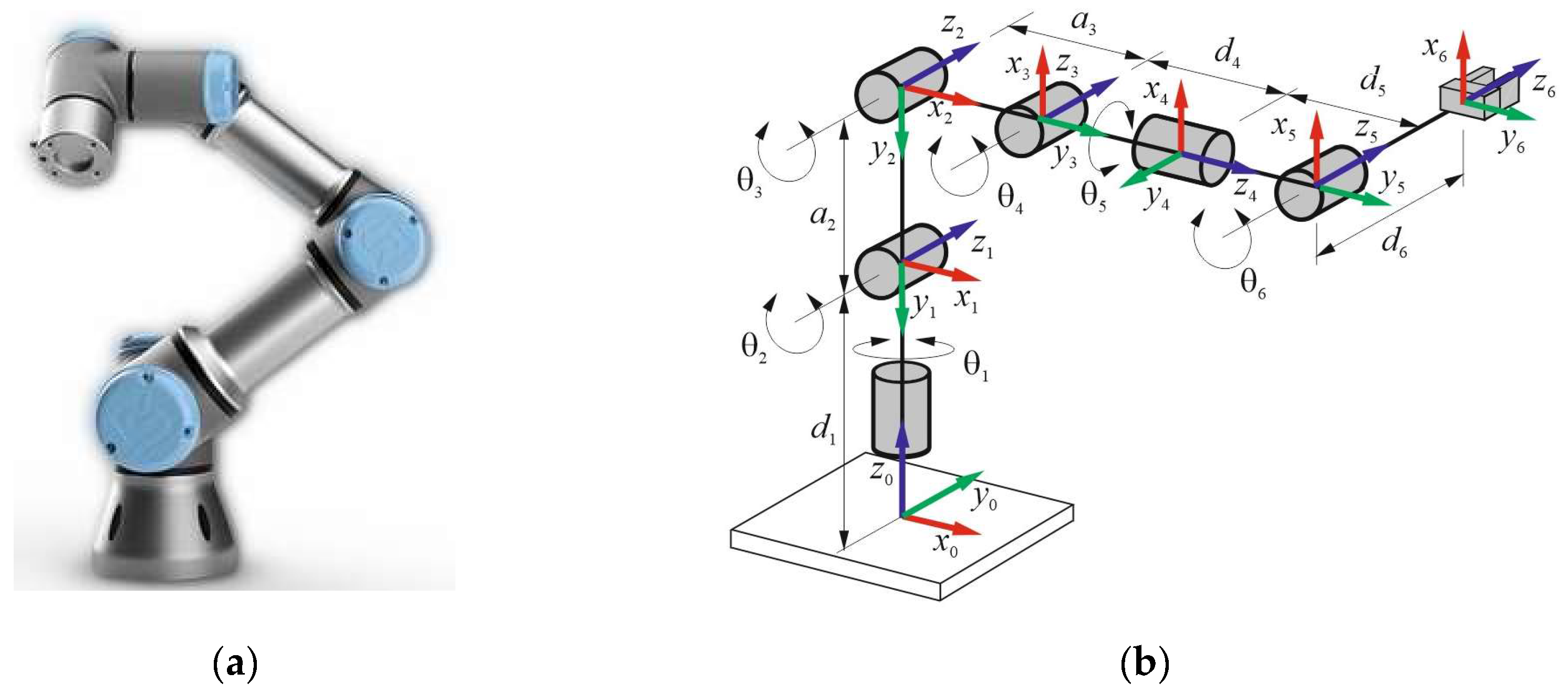
Figure 1 shows a typical 6R serial kinematic chain of 6 (DOFs), which also corresponds to that of the UR5e robotic arm (
Figure 1a), along with D-H reference frames (
Figure 1b). In particular, the fixed frame
x0y0z0 is attached to the robot base, while the
i-th moving frame
xiyizi is considered as attached to the
i-th link for
i = 1, …, 6, where the
zi - axis is along the joint axis direction, the
xi - axis is perpendicular to both
zi and
zi−1 axis, and the
yi-axis is chosen in agreement with the right-hand rule. The D-H parameters are reported in
Table 1, where
θi represents the joint angle variable of each UR5e joint,
di is the offset of the link, a
i denotes the length of the link,
αi indicates the joint torsion angle, where
i = 1, …, 6 is the joint number.
Thus, the homogeneous transformation matrix between the D-H reference frames that are associated to the joints
i−1 and
i, takes the form
2.1. Direct Kinematics
The DK problem for a serial kinematic chain consists of finding the position and orientation of the end-effector moving reference frame, when all the joint angles
θ i (
i = 1, …, 6) are given. Referring to
Table 1 and Eq. (1), the D-H homogeneous transformation matrices are obtained as follows
where c
i and s
i (
i = 1, …, 6) stand for
and
, respectively.
Consequently, the direct kinematics solution is obtained by multiplying in sequence and among them, the six homogeneous transform matrices of the Eq. (2), by giving the following
resultant matrix
This can be considered equal to the following 4x4 matrix
that includes the noa rotation matrix, whose entries are the Cartesian components of the corresponding unit vectors
n,
o, and
a, respectively, while (
px,
py,
pz) are those of the tool position vector
p.
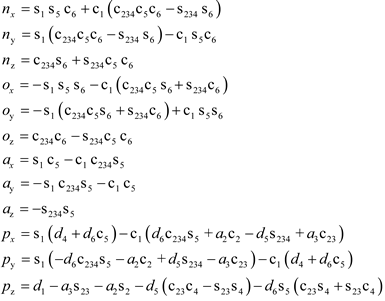
Thus, equating the corresponding entries of the matrices of Eq. (4), one has
where s and c stand for sine and cosine, respectively, and one has , , and .
2.2. Inverse Kinematics
The IK problem for a serial kinematic chain consists of finding the joint angles
θ i (
i = 1, …6) of the serial kinematic chain, when the position and orientation of the end-effector is given in terms of the noap Cartesian components. The required end-effector pose is given by the Eq. (4) and thus, multiplying each side of it by the inverse matrix
, it obtains the following matrix equation
where
is given by
and one has
Similarly, developing the right side of Eq. (6), one has
The joint angles
θ i for
i = 1, …, 6 are obtained by equating the right sides of the Eqs. (7) and (8), excluding the fourth row, and thus obtaining a system of twelve non-linear equations, which are coupled two by two, in order to obtain six sub-systems of two equations for each. In particular, developing the first sub-system, which is obtained by equating the two entries of the third row with the columns three and four,
θ 1 is given by
Likewise, the joint angles
θ 5 and
θ 6 are obtained by equating the two entries of the third row with the columns one and two. One has
The joint angle
θ 234 is obtained by equating the two entries of the first and second rows with the column three and after a suitable development, one has
Similarly, the joint angles
θ 2 and
θ 23 are obtained by equating the first and second rows with the fourth column and thus, one has
where the coefficients A and B are expressed as follows
Finally, referring to Eqs. (12), (13) and (14), the joint angles
θ 3 and
θ 4 are given by
2.3. Experimental Validation for One Pose
The proposed algorithms for solving the inverse and direct kinematics of the UR5e Cobot have been experimentally validated by referring to an arbitrary Cobot reference pose, which is given by the teach pendant in terms of the tool position vector p and the rotation vector r, along with the joint angles
θ i for
i = 1, …, 6, respectively. Vectors p and r have Cartesian components with respect to the base frame of (
px,
py,
pz) and (
rx,
ry,
rz), respectively. In particular, the rotation vector r of magnitude
θ, define the rotation axis of the tool end-effector, along with the corresponding rotation angle
θ, which is not a joint angle, since referred to the axis of unit vector u. In fact, one has
where
rx,
ry and
rz are the Cartesian components of r with respect to base frame.
Consequently, the homogeneous transformation matrix
, which includes the noa rotation matrix that corresponds to a given rotation vector r of angle
θ and unit vector u, along with the tool position vector p, can be expressed as follows
Therefore, referring to
Table 2 that contains the experimental Cartesian components of vectors
p and
r for the assigned UR5e Cobot pose, applying Eqs. (18) and (19) to determine the rotation angler
θ = 3.1113 rad and the unit vector
, and finally substituting in Eq. (20), one has
According to the proposed IK algorithm, the assigned experimental Cartesian components of p and r of
Table 2, the corresponding joint angles
θ i for
i = 1, …6 are reported in
Table 3, as follows
Likewise, the DK is solved by using as input data, the joint angles
θ i for
i = 1, …6 of
Table 3, which are substituted into the Eq. (2) in order to obtain the whole homogeneous transformation matrix
of Eq. (3), as follows
However, the teach pendant of the UR5e Cobot gives the tool end-effector pose in terms of p and r components, for which, the following matrix is introduced
where the first three numbers of the fourth column of Eq. (22) correspond to the Cartesian components of vector p, respectively.
Developing Eq. (23), one has
and thus, the rotation vector r is given by
which numerical results, along with p, are reported in
Table 4, as follows
This experimental validation procedure of the proposed algorithm for the UR5e Cobot direct and inverse kinematics is extensively applied in the next session by referring to the robotized assembling of a multi-cylinder IC engine. Particular attention will be devoted to the first Operation of the whole automatic cycle and then all Cobot poses will be also considered for the validation purposes of the proposed kinematic model.
3. Application: Robotized Assembling of a Multi-Cylinder IC Engine
A specific industrial application regarding the robotized assembling of a multi-cylinder IC engine, has been designed in terms of layout and corresponding automatic cycle that is intended as a sequence of the robot elementary actions. In particular, the proposed robotized cell is composed by the UR5e Cobot along with its controller and a suitable electropneumatic circuit that includes a PLC with its user interface, which are both governed by means of a specific electronic board and a switch control box.
Referring to
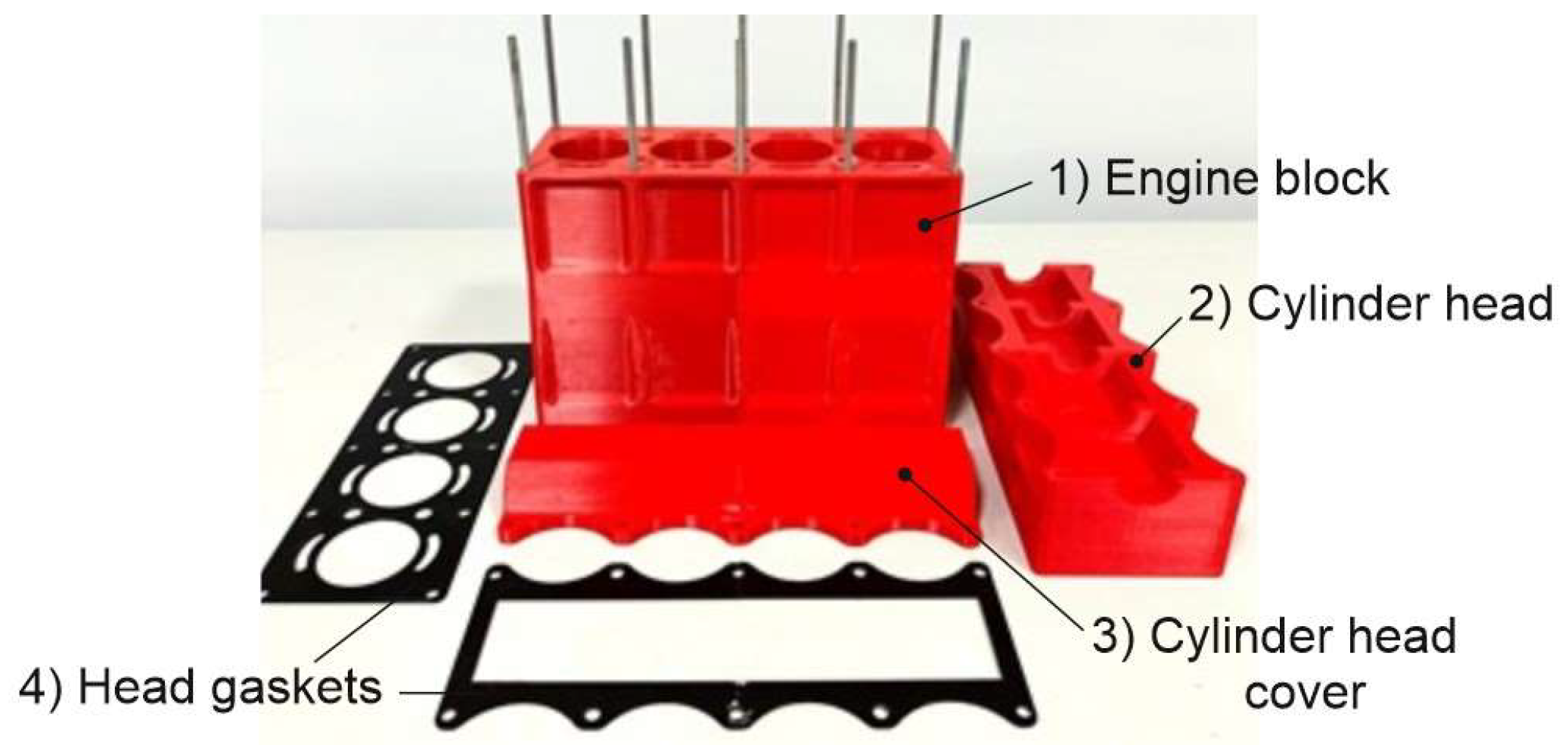
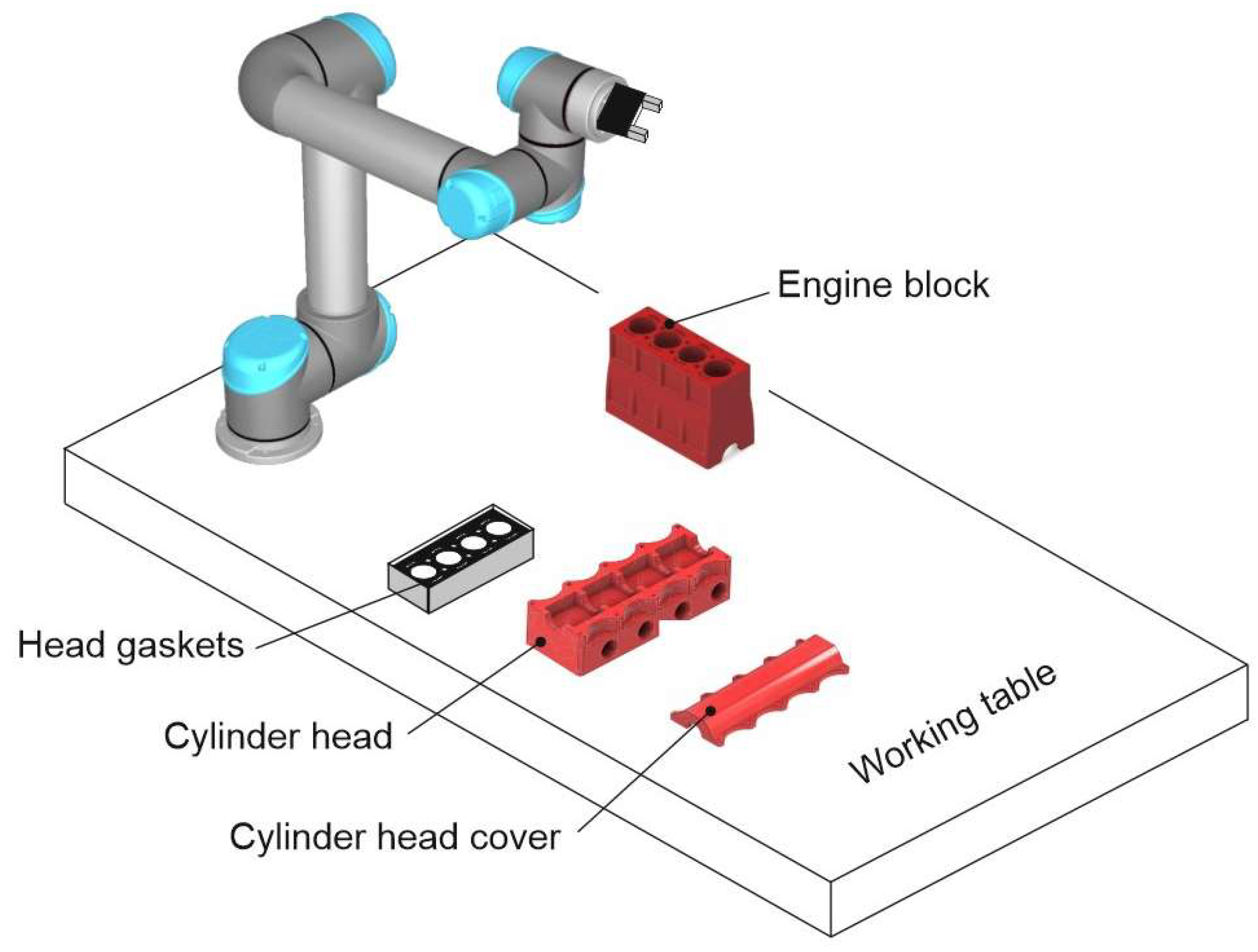
Figure 2, the robotized assembling of a multi-cylinder IC engine is carried out by means of a suitable automatic cycle and in agreement with the main engine components, which are: 1) engine block; 2) cylinder head; 3) cylinder head cover; 4) head gaskets. Consequently, these components are suitably positioned on a working table and in such a way to be reachable by the Cobot end-effector, as sketched in
Figure 3.
The automatic cycle has been conceived of five fundamental operations, where four consist of the assembling of the following components on the engine block that is fixed on the working table: 1) the first head gasket; 2) the cylinder head; 3) the second head gasket; 4) the cylinder head cover. The fifth operation consists of the nut screwing in order to assembly all engine components safely. Moreover, each operation has been distinguished in a suitable number of elementary actions. The proposed Cobot kinematic model has been further validated during a manipulation and not only in a given pose.
3.1. Automatic Cycle: Operation 1
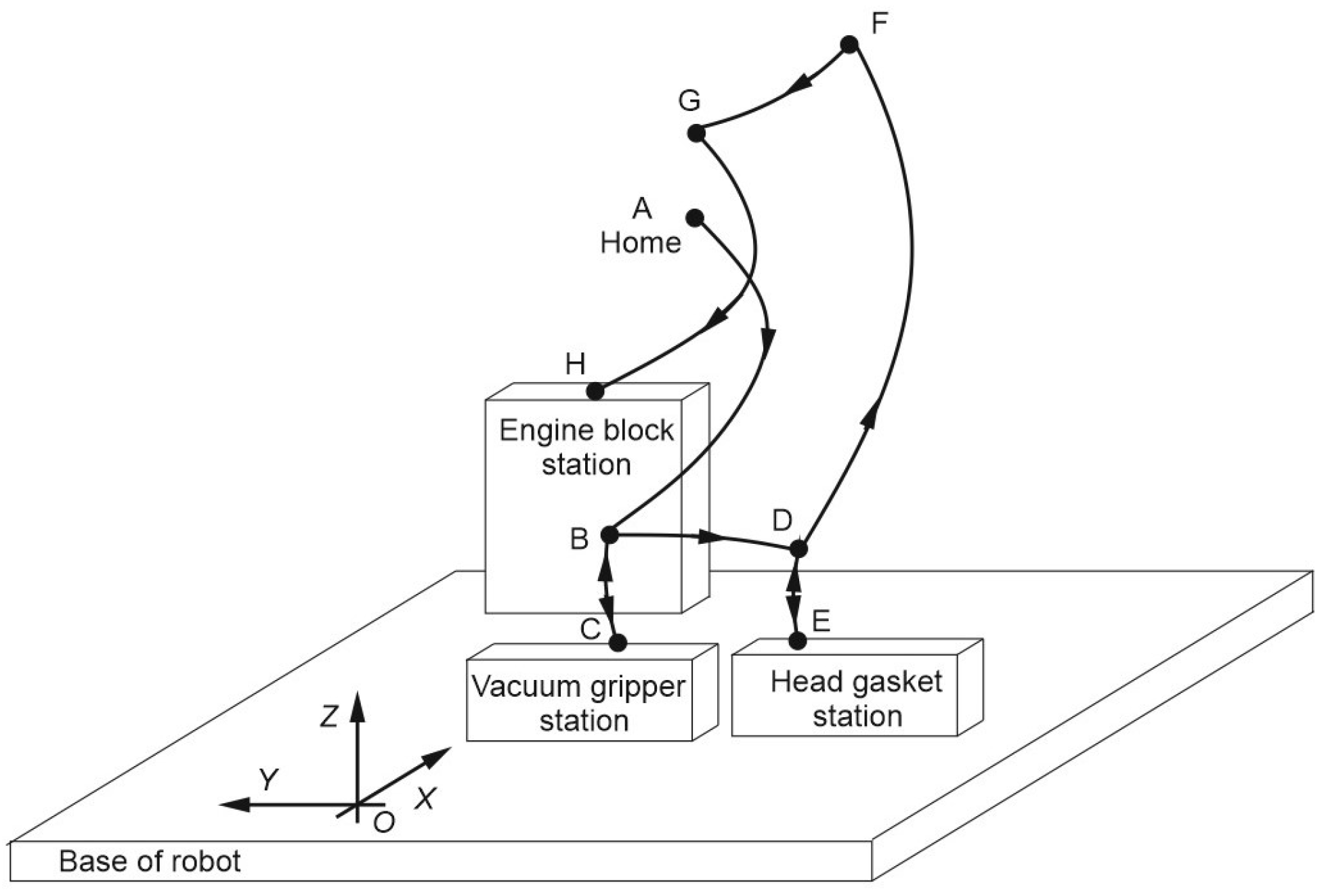
The first operation of the whole automatic cycle is aimed to assemble the first head gasket on the fixed cylinder block, which elementary actions, starting by the home Cobot position (A) and referring to the sketch of
Figure 4, are: 1) the end-effector reaches the position B; 2) it grasps the vacuum gripper in C; 3) it moves back to B; 4) it moves to D; 5) it grasps the first head gasket in E; 6) it moves to F; 7) it moves to G; 8) it assembles the first head gasket on the cylinder block in H.
Therefore, referring to
Table 5, which contains the Cartesian components of vectors
p and
r for each Cobot pose, which corresponds to the end-effector position from A to H for the Operation 1, the proposed IK Cobot model has allowed to determine all the corresponding joint angles
θ i for
i = 1, …, 6.
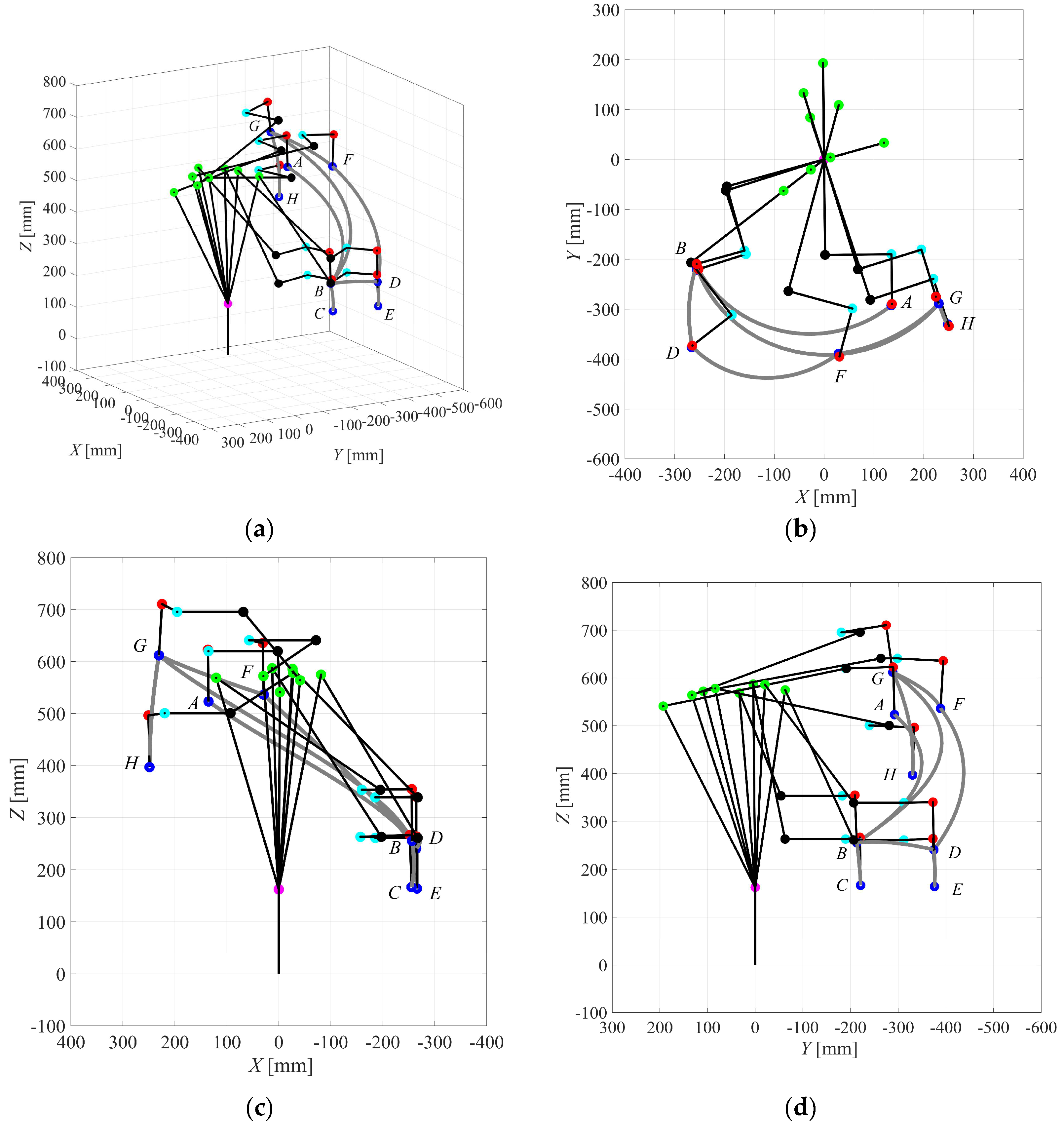
Moreover, the proposed IK Cobot model has been implemented in Matlab by giving the graphical result of
Figure 5 for the Operation 1, along with the corresponding joint angles of
Table 6. This has allowed the experimental validation of the proposed Cobot kinematic model during a manipulation and not only in a given pose, as in session 2.3.
In fact, referring to the Operation 1 of
Figure 4 and the assigned input data of
Table 5, the numerical and experimental six joint angles
θ i for
i = 1, …, 6 of the UR5e Cobot have been obtained by the proposed IK Cobot model and the tech-pendant screen, respectively. These results can be correspondingly compared among them, by showing a very good approximation between the numerical and the experimental results.
Thus, the proposed parametric and open-source algorithm for the direct and inverse kinematics of the Cobot UR5e has been experimentally validated with a good reliability. Moreover, a further validation has been carried out by calculating both the position and the orientation vectors p and r for each joint and pose of the Cobot UR5e, as reported in
Table 7 along with the graphical representation of
Figure 5, which shows the Cobot kinematic chain in each pose of the Operation 1. In particular,
Figure 5 (a) shows a 3 D view, while
Figure 5 (b),
Figure 5 (c) and
Figure 5 (d) show the XY, XZ and the YZ planar views.
The same approach has been used to analyze and simulate the other four Operations of the whole automatic cycle, as reported in the next section.
3.2. Automatic Cycle: Operations 2 to 5
Using the same approach that has been applied in section 3.1 and referring to the Operations 2 to 5, since the first was considered in the previous section, the numerical and the experimental joint angles have been determined with reference to the input data of
Table 8 for the end-effector position and the orientation vectors
p and
r.
According to the Cobot UR5e inverse kinematics, the numerical results in terms of joint angles are reported on the left side of
Table 9, while the corresponding experimental results are shown on the right side. A good approximation is obtained by comparing the corresponding numerical and experimental joint angles.
Moreover, the
Pj points could for
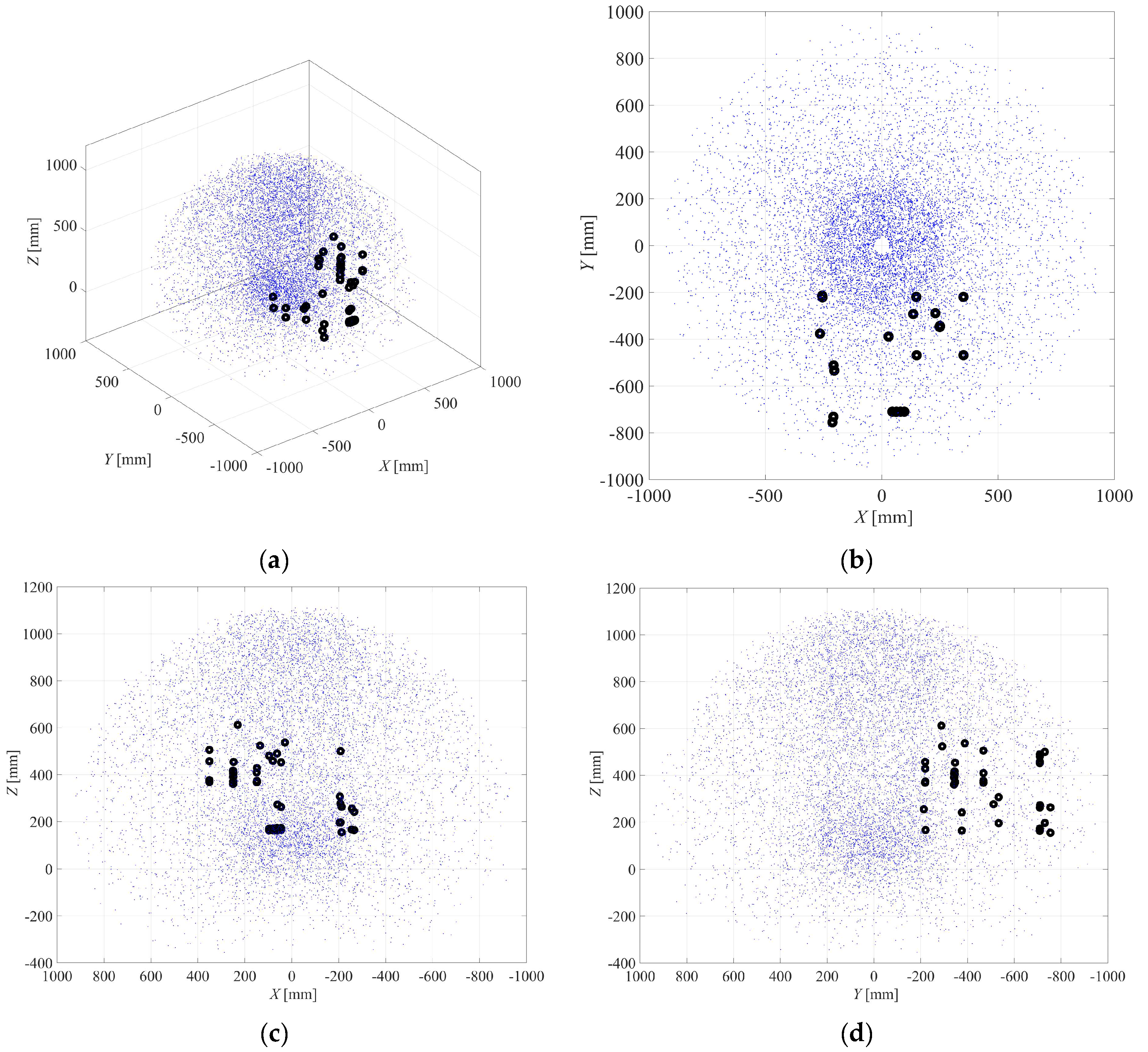
j = 1 to 39, which correspond to the Operations 2 to 5 of the whole automatic cycle of the robotized work cell, are graphically shown in
Figure 6, along with the 8 points, from A to H, of the Operation 1, for a total of 47 points, which fall inside the Cobot workspace. In particular, the 3D view is shown in
Figure 6 (a), while
Figure 6 (b),
Figure 6 (c) and
Figure 6 (d) show its XY, XZ, and YZ planar projections.
3.3. Experimental Set-Up of the Robotized Work Cell
According to the sketch of
Figure 3, the whole robotized work cell for assembling a multi-cylinder IC engine has been designed and built at LARM (Laboratory of Robotics and Mechatronics) of DICEM (Department of Civil and Mechanical Engineering) of the University of Cassino and Southern Lazio. This has required the mechatronic design, along with the building and the assembling of other suitable devices and systems, which cooperate among them and with the UR5e Cobot according to a specific automatic cycle.
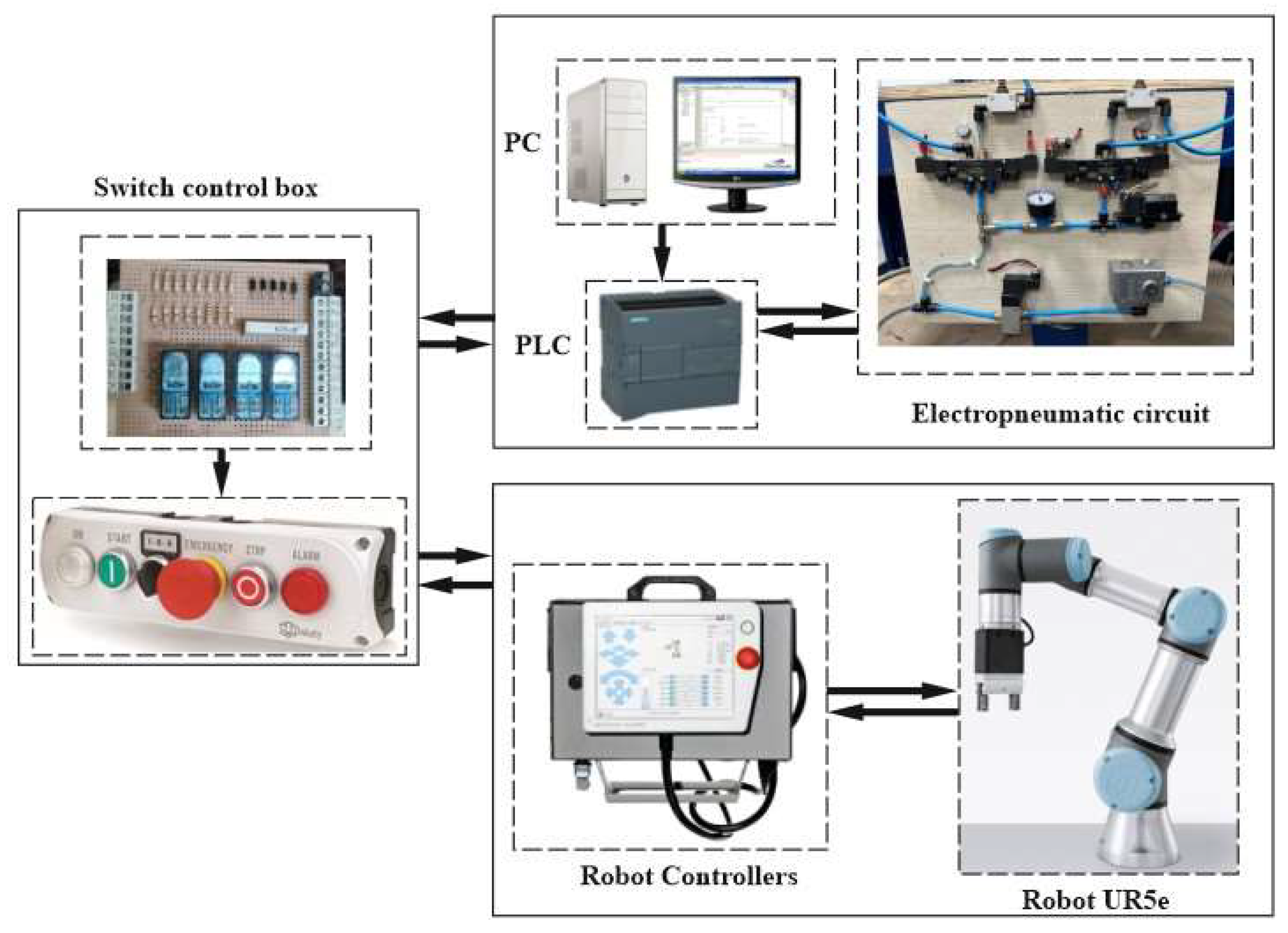
In particular, the mechatronic scheme of the proposed robotized work cell is shown in
Figure 7, where the UR5e Cobot and its controller cooperate with a suitable electropneumatic system that is controlled and programmed through a PLC of Siemens S7-1200 type. Both automatic systems are governed by means of a suitable switch control box, which is installed on the working table.
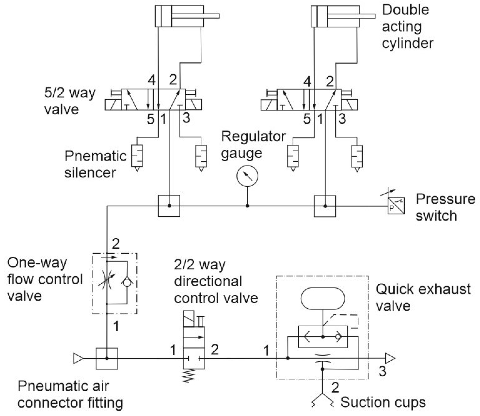
A detail on the electropneumatic circuit is shown in
Figure 8, which can be considered as composed by two main parts, where the first part is devoted to perform the vacuum grasp by means of four suction-cups and ejectors (only one is shown in
Figure 8), where each of them is provided by a suitable quick exhaust valve, while the second part of the electropneumatic circuit refers to the locking device of the engine block, which is mainly composed by two double-acting pneumatic cylinders, along with their operating electrovalves of 5/2 type.
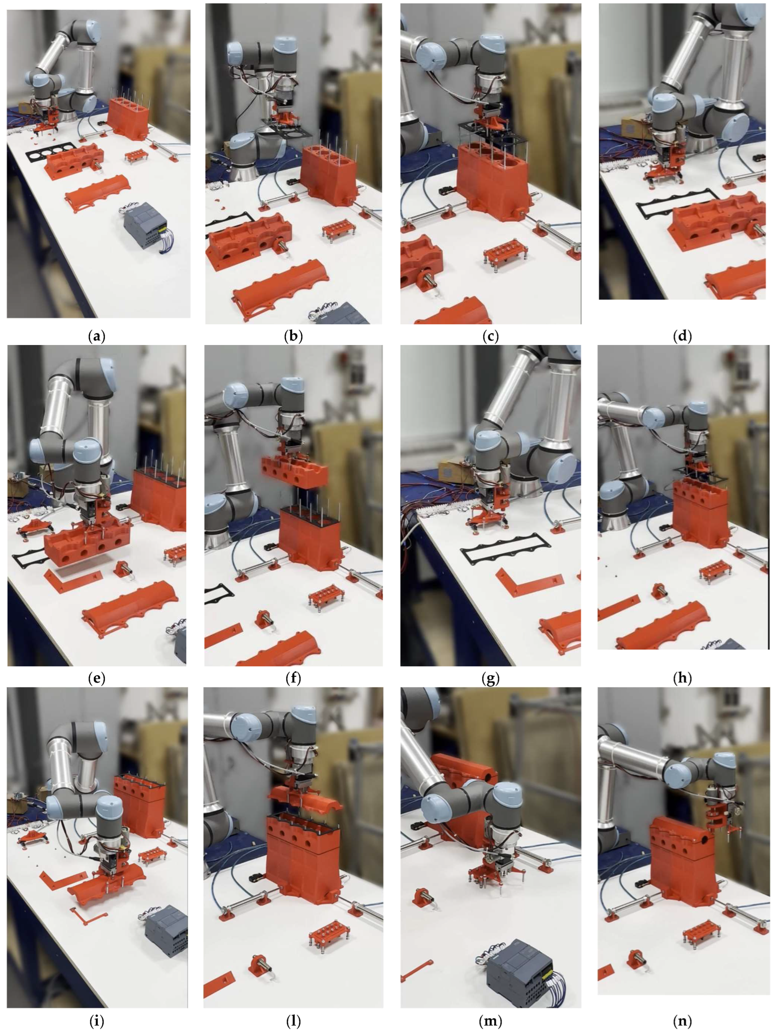
Therefore, the whole robotized work cell for assembling a multi-cylinder IC engine has been experimentally tested at LARM according to the proposed automatic cycle, which is composed by five main Operations.
Referring to
Figure 9, the Cobot end-effector: grasps the vacuum gripper (
Figure 9a); grasps the first head gasket (
Figure 9b); assembles it on the cylinder block (
Figure 9c); releases the vacuum gripper (
Figure 9d); grasps the cylinder head (
Figure 9e); assembles the cylinder head by using the two-finger gripper (
Figure 9f); grasps the vacuum gripper (
Figure 9g); assembles the second head gasket (
Figure 9h); release the vacuum gripper and grasps the cylinder head cover (
Figure 9i); assembles the cylinder cover on the block (
Figure 9l); grasps a nut (
Figure 9m); screws one nut for time by using the torque limiting screwdriver (
Figure 9n).
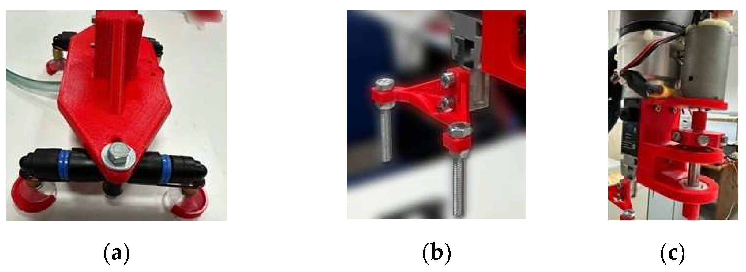
Moreover, the IC engine in scale of 1:5 and specific parts of the end-effector, have been designed and manufactured by using a 3D printer. Referring to
Figure 10, these specific parts consist of the four suction cups of the vacuum gripper (
Figure 10a), the two-finger gripper (
Figure 10b) and the torque limiting screwdriver (
Figure 10c).
Figure 1.
UR5e Cobot: a) a 3D view; b) D-H reference frames.
Figure 1.
UR5e Cobot: a) a 3D view; b) D-H reference frames.
Figure 2.
Multi-cylinder IC engine: main components.
Figure 2.
Multi-cylinder IC engine: main components.
Figure 3.
Robotized work cell: working table.
Figure 3.
Robotized work cell: working table.
Figure 4.
Operation 1 of the automatic cycle: elementary actions.
Figure 4.
Operation 1 of the automatic cycle: elementary actions.
Figure 5.
Operation 1: (a) 3D view; (b) XY-plane; (c) XZ-plane; (d) YZ-plane.
Figure 5.
Operation 1: (a) 3D view; (b) XY-plane; (c) XZ-plane; (d) YZ-plane.
Figure 6.
Automatic cycle – Operations 1 to 5 (workspace and points cloud): (a) 3D view; (b) XY-plane; (c) XZ-plane; (d) YZ-plane.
Figure 6.
Automatic cycle – Operations 1 to 5 (workspace and points cloud): (a) 3D view; (b) XY-plane; (c) XZ-plane; (d) YZ-plane.
Figure 7.
Robotized work cell: mechatronic scheme.
Figure 7.
Robotized work cell: mechatronic scheme.
Figure 8.
The electro-pneumatic circuit.
Figure 8.
The electro-pneumatic circuit.
Figure 9.
Application: robotized assembling of a multi-cylinder IC engine.
Figure 9.
Application: robotized assembling of a multi-cylinder IC engine.
Figure 10.
End-effector devices: a) suction cups of the vacuum gripper; b) two-finger gripper; c) torque limiting screwdriver.
Figure 10.
End-effector devices: a) suction cups of the vacuum gripper; b) two-finger gripper; c) torque limiting screwdriver.
Table 1.
D-H parameters for the UR5e Cobot.
Table 1.
D-H parameters for the UR5e Cobot.
| Link number i
|
θ i [rad] |
di [mm] |
ai [mm] |
α i [rad] |
| 1 |
θ1
|
162.5 |
0 |
π / 2 |
| 2 |
θ2
|
0 |
− 425 |
0 |
| 3 |
θ3
|
0 |
− 392.2 |
0 |
| 4 |
θ4
|
133.3 |
0 |
π / 2 |
| 5 |
θ5
|
99.7 |
0 |
− π / 2 |
| 6 |
θ6
|
99.6 |
0 |
0 |
Table 2.
Cartesian components of p and r for the assigned UR5e Cobot pose.
Table 2.
Cartesian components of p and r for the assigned UR5e Cobot pose.
|
px [mm] |
py [mm] |
pz [mm] |
rx [rad] |
ry [rad] |
rz [rad] |
| 135.00 |
− 292.13 |
523.81 |
2.22 |
− 2.19 |
0.022 |
Table 3.
Joint angles for the assigned UR5e Cobot pose of
Table 2.
Table 3.
Joint angles for the assigned UR5e Cobot pose of
Table 2.
|
θ1 [°] |
θ2 [°] |
θ3 [°] |
θ4 [°] |
θ5 [°] |
θ6 [°] |
| 90.5785 |
−117.0569 |
105.3867 |
279.9306 |
− 90.7226 |
− 89.4325 |
Table 4.
Tool end-effector position and orientation.
Table 4.
Tool end-effector position and orientation.
|
px [mm] |
py [mm] |
pz [mm] |
rx [rad] |
ry [rad] |
rz [rad] |
| 135.1514 |
− 292.2861 |
523.2706 |
2.2012 |
− 2.2016 |
0.0178 |
Table 5.
Operation 1: experimental Cartesian components of vectors p and r for each Cobot pose.
Table 5.
Operation 1: experimental Cartesian components of vectors p and r for each Cobot pose.
| Point |
px [mm] |
py [mm] |
pz [mm] |
rx [rad] |
ry [rad] |
rz [rad] |
|
Home (A) |
135.00 |
− 292.13 |
523.81 |
2.22 |
− 2.19 |
0.022 |
| B |
− 256.31 |
− 213.52 |
255.33 |
2.22 |
− 2.18 |
0.040 |
| C |
− 255.12 |
− 220.86 |
166.42 |
2.22 |
− 2.22 |
− 0.021 |
| D |
− 265.84 |
− 375.95 |
241.53 |
2.22 |
− 2.21 |
0.021 |
| E |
− 265.72 |
− 375.91 |
163.90 |
2.21 |
− 2.22 |
0.021 |
| F |
29.16 |
− 388.82 |
536.41 |
3.14 |
− 0.001 |
− 0.032 |
| G |
230.32 |
− 288.63 |
612.22 |
3.01 |
− 0.011 |
0.094 |
| H |
250.10 |
− 344.72 |
417.03 |
3.14 |
− 0.031 |
0.001 |
Table 6.
IK Cobot model: Numerical and experimental joint angles θ i (i = 1, …, 6).
Table 6.
IK Cobot model: Numerical and experimental joint angles θ i (i = 1, …, 6).
| |
|
Numerical Joint Angles |
Experimental Joint Angles |
| Point |
θ1 [°] |
θ2 [°] |
θ3 [°] |
θ4 [°] |
θ5 [°] |
θ6 [°] |
θ1 [°] |
θ2 [°] |
θ3 [°] |
θ4 [°] |
θ5 [°] |
θ6 [°] |
| A |
90.5785 |
−117.0569 |
105.3867 |
279.9306 |
−90.7226 |
−89.4325 |
89.92 |
−1167.49 |
105.33 |
283.18 |
−88.73 |
−89.39 |
| B |
15.5453 |
−107.0629 |
140.3619 |
235.9249 |
−87.8703 |
−164.4402 |
15.35 |
−107.17 |
140.69 |
234.91 |
−87.93 |
−163.49 |
| C |
17.5589 |
−91.77808 |
147.6393 |
212.2606 |
−89.8548 |
−162.4388 |
17.67 |
−91.80 |
147.38 |
213.06 |
−90.27 |
−164.11 |
| D |
37.6901 |
−85.4407 |
124.6513 |
229.1634 |
−89.0490 |
−142.2964 |
37.87 |
−85.27 |
123.70 |
232.34 |
−89.50 |
−141.09 |
| E |
37.6981 |
−75.9854 |
129.2307 |
215.1258 |
−89.0492 |
−142.2884 |
37.85 |
−76.14 |
128.36 |
218.44 |
−89.51 |
−141.09 |
| F |
74.7950 |
−105.4460 |
95.2677 |
283.1362 |
−91.9135 |
−195.0839 |
75.01 |
−105.92 |
95.08 |
281.11 |
−91.08 |
−194.97 |
| G |
107.1736 |
−109.1401 |
89.5395 |
280.9065 |
−89.1269 |
−162.3781 |
107.03 |
−108.80 |
88.91 |
282.65 |
−88.53 |
−162.51 |
| H |
108.3671 |
−102.3689 |
113.4437 |
251.2545 |
−92.6226 |
−160.6629 |
107.57 |
−101.31 |
109.98 |
261.99 |
−89.49 |
−161.36 |
Table 7.
Operation 1: Numerical results for the Cartesian components of p and r for each joint in different poses.
Table 7.
Operation 1: Numerical results for the Cartesian components of p and r for each joint in different poses.
| Point |
Joint n. |
px [mm] |
py [mm] |
pz [mm] |
rx [rad] |
ry [rad] |
rz [rad] |
|
Home (A) |
1 |
0 |
0 |
162.5000 |
1.2042 |
1.2169 |
1.2169 |
| 2 |
− 2.0205 |
192.9354 |
541.1778 |
− 0.3774 |
1.5366 |
− 0.3613 |
| 3 |
2.0027 |
− 191.2330 |
620.0405 |
1.0530 |
1.3050 |
1.0666 |
| 4 |
135.2954 |
− 189.8371 |
620.0405 |
1.1810 |
1.1934 |
− 1.2145 |
| 5 |
136.3390 |
− 289.4927 |
622.8243 |
0.0161 |
− 3.1292 |
0.0438 |
| 6 |
135.1514 |
− 292.2861 |
523.2706 |
2.2012 |
− 2.2016 |
0.0178 |
| B |
1 |
0 |
0 |
162.5000 |
1.5603 |
0.2124 |
0.2124 |
| 2 |
120.4221 |
33.3960 |
568.7120 |
0.8237 |
1.5046 |
− 1.2297 |
| 3 |
− 195.4594 |
− 54.2057 |
353.3853 |
1.5909 |
− 0.2491 |
0.6652 |
| 4 |
− 159.8366 |
− 182.6576 |
353.3853 |
2.0614 |
0.2805 |
− 2.0904 |
| 5 |
− 255.902 |
− 209.2987 |
354.77773 |
1.8885 |
2.4841 |
− 0.0520 |
| |
6 |
− 256.2650 |
− 213.1871 |
255.2539 |
2.1983 |
− 2.2016 |
0.0390 |
| C |
1 |
0 |
0 |
162.5000 |
1.5573 |
0.2411 |
0.2411 |
| 2 |
12.7247 |
4.0365 |
587.2903 |
0.9615 |
1.3580 |
− 1.0037 |
| 3 |
− 197.4053 |
− 62.6207 |
262.9093 |
1.5704 |
− 0.5438 |
0.9932 |
| 4 |
− 157.0994 |
− 189.6810 |
262.9093 |
2.0175 |
0.3123 |
− 2.0892 |
| 5 |
− 252.0746 |
− 219.8089 |
266.3888 |
−1.8446 |
− 2.5205 |
0.0472 |
| 6 |
− 255.2828 |
− 221.1913 |
166.8500 |
2.1984 |
− 2.1983 |
− 0.0202 |
| D |
1 |
0 |
0 |
162.500 |
1.5087 |
0.5151 |
0.5151 |
| 2 |
− 26.3834 |
− 20.3914 |
586.1899 |
0.7651 |
1.4151 |
− 0.6517 |
| 3 |
− 267.2045 |
− 206.5191 |
338.8388 |
1.6707 |
− 0.0204 |
1.0378 |
| 4 |
− 185.6880 |
− 311.9892 |
338.8388 |
1.8299 |
0.6247 |
− 1.8524 |
| 5 |
− 264.5671 |
− 372.9539 |
340.0569 |
1.3805 |
2.8122 |
− 0.0280 |
| 6 |
− 264.5730 |
− 374.9358 |
240.4766 |
2.2096 |
− 2.2132 |
0.0220 |
| E |
1 |
0 |
0 |
162.5000 |
1.5087 |
0.5151 |
0.5151 |
| 2 |
− 81.3511 |
− 62.8753 |
574.8757 |
0.8722 |
1.3354 |
− 0.5232 |
| 3 |
− 267.2388 |
− 206.5456 |
260.8288 |
1.6974 |
− 0.2310 |
1.2208 |
| 4 |
− 185.7222 |
− 312.0157 |
260.8288 |
1.8118 |
0.6186 |
− 1.8664 |
| 5 |
− 264.5725 |
− 372.9581 |
263.7866 |
1.3829 |
2.8175 |
− 0.0539 |
| 6 |
− 265.8470 |
− 376.1401 |
164.2456 |
2.1993 |
− 2.1987 |
0.0211 |
| F |
1 |
0 |
0 |
162.5000 |
1.3231 |
1.0116 |
1.0116 |
| 2 |
29.5910 |
108.9131 |
572.2405 |
− 0.0028 |
1.5862 |
− 0.4186 |
| 3 |
− 71.6460 |
− 263.7012 |
641.0194 |
1.2109 |
1.1076 |
0.8781 |
| 4 |
56.9907 |
− 298.6510 |
641.0194 |
1.4456 |
1.1053 |
− 1.3719 |
| 5 |
30.8862 |
− 394.7313 |
635.8015 |
− 0.4106 |
− 3.0872 |
− 0.0877 |
| 6 |
29.0655 |
− 388.8379 |
536.3927 |
3.0823 |
− 0.0014 |
− 0.0282 |
| G |
1 |
0 |
0 |
162.5000 |
1.0519 |
1.4268 |
1.4268 |
| 2 |
−41.1234 |
132.8483 |
564.1033 |
− 0.4893 |
1.4927 |
− 0.0260 |
| 3 |
68.1333 |
− 220.1031 |
695.6674 |
0.7623 |
1.5222 |
1.1783 |
| 4 |
195.4719 |
− 180.6852 |
695.6674 |
0.8933 |
1.2117 |
− 1.0386 |
| 5 |
224.6225 |
− 274.8556 |
710.5761 |
− 0.4647 |
3.0603 |
− 0.2265 |
| 6 |
230.5206 |
− 288.6189 |
612.1081 |
3.0017 |
− 0.0087 |
0.0900 |
| H |
1 |
0 |
0 |
162.5000 |
1.0408 |
1.4405 |
1.4405 |
| 2 |
− 27.7451 |
83.8936 |
578.2127 |
− 0.4107 |
1.5168 |
0.0864 |
| 3 |
92.9731 |
− 281.1248 |
500.6915 |
1.2119 |
1.3673 |
1.5799 |
| 4 |
219.5315 |
− 239.2696 |
500.6915 |
0.9959 |
1.3784 |
− 0.9551 |
| 5 |
250.8091 |
− 333.8443 |
496.5165 |
0.4973 |
− 3.0859 |
− 0.0625 |
| 6 |
248.6744 |
− 330.1575 |
397.0077 |
− 3.1044 |
0.0295 |
0.0338 |
Table 8.
Automatic cycle: Operations 2 to 5.
Table 8.
Automatic cycle: Operations 2 to 5.
| Point |
px [mm] |
py [mm] |
pz [mm] |
rx [rad] |
ry [rad] |
rz [rad] |
| P1
|
249.70 |
− 342.81 |
360.58 |
3.16 |
− 0.02 |
0.004 |
| P2
|
− 204.10 |
− 533.41 |
306.78 |
2.22 |
− 2.25 |
0.013 |
| P3
|
− 204.10 |
− 533.41 |
195.63 |
2.22 |
− 2.25 |
0.013 |
| P4
|
− 207.12 |
− 511.45 |
276.62 |
2.22 |
− 2.25 |
0.013 |
| P5
|
247.87 |
− 346.82 |
454.02 |
3.16 |
0.02 |
0.03 |
| P6
|
249.59 |
− 345.17 |
371.00 |
3.16 |
− 0.02 |
0.03 |
| P7
|
249.47 |
− 343.13 |
404.36 |
3.16 |
0.03 |
0.04 |
| P8
|
249.88 |
− 343.05 |
391.14 |
3.16 |
0.04 |
0.04 |
| P9
|
− 212.24 |
− 754.73 |
262.86 |
2.22 |
− 2.23 |
− 0.004 |
| P10
|
− 212.26 |
− 754.73 |
154.67 |
2.22 |
− 2.23 |
− 0.004 |
| P11
|
− 208.00 |
− 730.99 |
196.68 |
2.22 |
− 2.23 |
− 0.004 |
| P12
|
− 208.00 |
− 730.99 |
500.27 |
2.22 |
− 2.23 |
− 0.004 |
| P13
|
249.43 |
− 343.44 |
407.36 |
3.16 |
0.03 |
− 0.007 |
| P14
|
249.43 |
− 343.44 |
391.06 |
3.16 |
0.03 |
− 0.007 |
| P15
|
45.39 |
− 709.32 |
262.09 |
3.14 |
− 0.02 |
− 0.003 |
| P16
|
45.38 |
− 709.34 |
172.66 |
3.14 |
− 0.02 |
− 0.003 |
| P17
|
45.43 |
− 709.33 |
164.43 |
3.14 |
− 0.02 |
− 0.003 |
| P18
|
62.98 |
− 709.34 |
172.67 |
3.14 |
− 0.02 |
− 0.003 |
| P19
|
62.97 |
− 709.34 |
489.97 |
3.14 |
− 0.02 |
− 0.003 |
| P20
|
350.91 |
− 219.13 |
457.07 |
2.23 |
2.21 |
− 0.003 |
| P21
|
350.91 |
− 219.13 |
369.34 |
2.23 |
2.21 |
− 0.003 |
| P22
|
80.48 |
− 709.35 |
458.41 |
3.14 |
− 0.02 |
− 0.003 |
| P23
|
62.97 |
− 709.34 |
162.52 |
3.14 |
− 0.02 |
− 0.003 |
| P24
|
80.01 |
− 709.34 |
170.84 |
3.14 |
− 0.02 |
− 0.003 |
| P25
|
79.98 |
− 709.34 |
163.14 |
3.14 |
− 0.02 |
− 0.003 |
| P26
|
148.41 |
− 219.39 |
428.21 |
2.19 |
− 2.25 |
− 0.001 |
| P27
|
148.41 |
− 219.39 |
373.21 |
2.19 |
− 2.25 |
− 0.001 |
| P28
|
148.14 |
− 218.82 |
368.50 |
2.19 |
− 2.25 |
− 0.001 |
| P29
|
96.81 |
− 709.35 |
480.33 |
3.14 |
− 0.02 |
− 0.003 |
| P30
|
96.83 |
− 709.36 |
169.82 |
3.14 |
− 0.02 |
− 0.003 |
| P31
|
96.85 |
− 709.35 |
163.01 |
3.14 |
− 0.02 |
− 0.003 |
| P32
|
351.10 |
− 468.05 |
505.43 |
2.23 |
2.21 |
− 0.003 |
| P33
|
351.10 |
− 468.07 |
376.59 |
2.23 |
2.21 |
− 0.003 |
| P34
|
351.10 |
− 468.05 |
368.62 |
2.23 |
2.21 |
− 0.003 |
| P35
|
45.39 |
− 709.32 |
262.09 |
3.14 |
− 0.02 |
− 0.003 |
| P36
|
45.36 |
− 709.32 |
452.23 |
3.14 |
− 0.02 |
− 0.003 |
| P37
|
149.74 |
− 468.35 |
409.49 |
2.19 |
− 2.25 |
− 0.001 |
| P38
|
149.76 |
− 468.34 |
368.40 |
2.19 |
− 2.25 |
− 0.001 |
| P39
|
61.33 |
− 710.24 |
272.55 |
3.14 |
− 0.03 |
− 0.001 |
Table 9.
Operations 2 to 5: Numerical and experimental joint angles θ i (i = 1, …, 6).
Table 9.
Operations 2 to 5: Numerical and experimental joint angles θ i (i = 1, …, 6).
| |
|
Numerical Joint Angles |
Experimental Joint Angles |
| Point |
θ1 [°] |
θ2 [°] |
θ3 [°] |
θ4 [°] |
θ5 [°] |
θ6 [°] |
θ1 [°] |
θ2 [°] |
θ3 [°] |
θ4 [°] |
θ5 [°] |
θ6 [°] |
| P1
|
107.6365 |
−99.3506 |
117.1694 |
253.1430 |
−89.5350 |
−161.6433 |
107.57 |
−99.60 |
116.06 |
254.39 |
− 89.56 |
− 161.88 |
| P2
|
55.4440 |
−76.0835 |
101.2743 |
245.8053 |
−89.3297 |
−123.7928 |
55.36 |
−76.52 |
100.45 |
246.85 |
− 89.30 |
− 123.86 |
| P3
|
55.3847 |
−67.5512 |
108.7537 |
229.7942 |
−89.3307 |
−123.8521 |
55.35 |
−68.33 |
108.27 |
230.86 |
− 89.35 |
− 125.19 |
| P4
|
53.8547 |
−76.5769 |
106.8856 |
240.7056 |
−89.3576 |
−125.3819 |
53.76 |
−77.12 |
106.13 |
241.79 |
− 89.33 |
− 124.87 |
| P5
|
106.9999 |
−101.6459 |
105.1439 |
267.2125 |
−88.6524 |
−163.7341 |
106.71 |
−101.65 |
103.86 |
268.53 |
− 88.64 |
− 163.99 |
| P6
|
107.2986 |
−99.6532 |
115.8993 |
254.4402 |
−88.6399 |
−161.9843 |
106.94 |
−99.95 |
114.79 |
255.92 |
− 88.56 |
− 162.26 |
| P7
|
107.2833 |
−101.1141 |
112.0731 |
259.6551 |
−88.3009 |
−163.8136 |
106.95 |
−101.36 |
110.97 |
260.96 |
− 88.43 |
− 164.28 |
| P8
|
107.3434 |
−100.6818 |
113.7019 |
257.6038 |
−88.3004 |
−164.1163 |
107.01 |
−100.98 |
112.64 |
258.91 |
− 88.44 |
− 164.32 |
| P9
|
64.5092 |
−45.9403 |
61.4529 |
254.8084 |
−90.0401 |
−115.2331 |
64.51 |
−46.20 |
60.45 |
256.33 |
− 89.82 |
− 115.30 |
| P10
|
64.5079 |
−40.0146 |
67.4887 |
2424.8470 |
−90.0401 |
−115.2345 |
64.50 |
−40.45 |
66.91 |
244.21 |
− 89.83 |
− 115.27 |
| P11
|
64.0138 |
−45.8566 |
71.6477 |
244.5296 |
−90.0429 |
−115.7286 |
64.02 |
−46.33 |
70.95 |
245.96 |
− 89.84 |
− 115.76 |
| P12
|
64.0073 |
−49.9489 |
33.2644 |
287.0053 |
−90.0429 |
−115.7351 |
64.03 |
−49.06 |
30.27 |
289.36 |
− 89.79 |
− 115.86 |
| P13
|
107.6691 |
−100.9279 |
111.3508 |
260.6680 |
−89.9295 |
−163.4194 |
107.74 |
−101.04 |
110.22 |
261.57 |
− 89.98 |
− 163.23 |
| P14
|
107.6691 |
−100.4465 |
113.4000 |
258.1374 |
−89.9295 |
−163.4194 |
107.74 |
−101.61 |
112.30 |
259.06 |
− 89.98 |
− 163.23 |
| P15
|
82.8660 |
− 56.0413 |
79.0811 |
246.8603 |
−90.0984 |
−186.4042 |
82.91 |
−56.55 |
78.44 |
248.18 |
− 89.98 |
− 186.47 |
| P16
|
82.8344 |
−50.2574 |
83.8791 |
236.3032 |
−89.8807 |
−186.5817 |
82.90 |
−50.97 |
83.53 |
237.49 |
− 90.00 |
− 186.45 |
| P17
|
82.8383 |
−49.6330 |
84.1870 |
235.3772 |
−89.8807 |
−186.5777 |
82.90 |
−50.36 |
83.85 |
236.56 |
− 90.00 |
− 186.45 |
| P18
|
84.2996 |
−50.0972 |
83.5904 |
236.4094 |
−90.1009 |
−184.9706 |
84.33 |
−50.81 |
83.24 |
237.63 |
− 90.00 |
− 185.02 |
| P19
|
84.2988 |
−60.0954 |
51.5179 |
2784793 |
−90.1009 |
−184.9714 |
84.35 |
−59.06 |
45.24 |
283.87 |
− 89.94 |
− 185.11 |
| P20
|
129.2453 |
−103.6014 |
106.3970 |
267.0796 |
−90.0980 |
−230.2387 |
129.33 |
−103.66 |
105.13 |
268.50 |
− 90.05 |
− 230.04 |
| P21
|
129.2358 |
−101.5551 |
117.9751 |
253.0543 |
−90.0607 |
−229.9885 |
129.30 |
−101.86 |
116.74 |
255.09 |
− 90.07 |
− 230.04 |
| P22
|
85.7261 |
−60.3614 |
56.5674 |
273.6991 |
−90.1033 |
−183.5441 |
85.78 |
−60.29 |
55.10 |
275.25 |
− 89.95 |
− 183.66 |
| P23
|
84.2988 |
−49.3263 |
83.9575 |
235.2715 |
−90.1009 |
−184.9714 |
84.33 |
−50.06 |
83.64 |
236.48 |
− 90.00 |
− 185.02 |
| P24
|
85.6877 |
−49.7631 |
83.2668 |
236.3714 |
−90.1032 |
−183.5825 |
85.72 |
−50.48 |
82.95 |
237.59 |
− 89.99 |
− 183.63 |
| P25
|
85.6869 |
−49.1795 |
83.5740 |
235.5107 |
−90.1032 |
−183.5833 |
85.71 |
−49.91 |
83.25 |
236.72 |
− 89.99 |
− 183.63 |
| P26
|
93.9046 |
−128.0236 |
123.5710 |
274.4155 |
−90.1001 |
−84.5470 |
93.85 |
−127.87 |
122.20 |
275.78 |
− 89.99 |
− 84.92 |
| P27
|
93.8978 |
−128.0929 |
131.6145 |
266.3776 |
−90.1001 |
−84.5538 |
93.81 |
−128.16 |
130.34 |
267.93 |
− 89.92 |
− 84.92 |
| P28
|
93.8468 |
−128.1713 |
132.3510 |
265.7830 |
−90.1001 |
−84.6048 |
93.75 |
−128.25 |
131.06 |
267.30 |
− 89.92 |
− 84.99 |
| P29
|
87.0558 |
−59.6669 |
52.2767 |
277.2964 |
−90.1053 |
−182.3640 |
87.11 |
−59.49 |
50.64 |
278.91 |
− 89.94 |
− 182.34 |
| P30
|
87.0575 |
−49.4445 |
82.8882 |
236.4625 |
−90.1053 |
−182.3587 |
87.09 |
−50.16 |
82.55 |
237.67 |
− 89.99 |
− 182.26 |
| P31
|
87.0590 |
−48.9304 |
83.1335 |
235.7032 |
−90.1053 |
−182.3571 |
87.09 |
−49.66 |
82.81 |
236.91 |
− 89.99 |
− 182.26 |
| P32
|
113.7164 |
−79.3580 |
75.4713 |
273.7401 |
−90.0610 |
−245.7675 |
113.79 |
−79.34 |
74.42 |
274.87 |
− 89.97 |
− 245.61 |
| P33
|
113.7138 |
−77.6356 |
92.6656 |
254.8234 |
−90.0610 |
−245.7701 |
113.77 |
−77.99 |
91.73 |
256.21 |
− 90.00 |
− 245.58 |
| P34
|
113.7155 |
−77.3475 |
93.5163 |
253.6847 |
−90.0610 |
−245.7684 |
113.77 |
−77.72 |
92.59 |
255.08 |
− 90.00 |
− 245.58 |
| P35
|
82.8660 |
−56.0415 |
79.0819 |
246.8584 |
−90.0981 |
−186.5502 |
82.91 |
−56.55 |
78.44 |
248.18 |
− 89.99 |
− 186.47 |
| P36
|
82.8635 |
−60.9276 |
58.3409 |
272.4855 |
−90.0981 |
−186.5526 |
82.92 |
−60.88 |
56.91 |
274.03 |
− 89.95 |
− 186.52 |
| P37
|
92.0212 |
−91.4461 |
102.9689 |
258.4368 |
−90.0989 |
−86.4304 |
92.02 |
−91.68 |
101.84 |
259.95 |
− 89.87 |
− 86.75 |
| P38
|
92.0237 |
−89.9950 |
107.7454 |
252.2092 |
−90.0989 |
−86.4279 |
92.01 |
−90.37 |
106.72 |
253.76 |
− 89.88 |
− 86.75 |
| P39
|
84.1624 |
−56.3150 |
77.8781 |
248.3497 |
−90.0285 |
−184.8159 |
84.19 |
−56.90 |
77.43 |
249.29 |
− 89.89 |
− 184.75 |
