1. Introduction
TETRA (Terrestrial Trunked Radio, formerly known as Trans-European Trunked Radio) is a professional trunked European radio system standard that has been in use since the 1990’s across the globe. TETRA uses frequencies in the lower end of the UHF (Ultra High Frequency) band. The relatively low frequency, typically in the 400 MHz range, allows it to provide a larger coverage area. TETRA is used worldwide for Radio Frequency (RF) communications by emergency services, militaries, transportation and for commercial use in critical infrastructure [
1]. It can be used for both voice and data communications to issue SCADA WAN (Wide Area Network) commands for substation control, for example. Although TETRA is not commonly used in the US by government agencies and emergency services, it is used in commercial critical infrastructure such as offshore electrical substations.
The main network components of a TETRA system are [
2]:
Base Station (BS): The function of a base station is to link the Mobile stations and line stations through an Integrated Services Digital Network (ISDN).
Mobile Station (MS): Mobile station equipment includes a Mobile Termination Unit and Terminal Equipment. Its function is to communicate back to the Base Station or directly to other mobile stations through the Air Interface. Direct communication is also referred to as Direct Mode Operation (DMO).
Line Station (LS): A line station has a similar function to a mobile station but uses an ISDN to connect to the base station rather than the air interface.
Network Management Unit: The network management unit provides local and remote communications to the base station. These connections include line stations or other base stations on the same network.
Gateway: A gateway connects the TETRA network to other external networks such as Private Telephone Networks and ISDN.
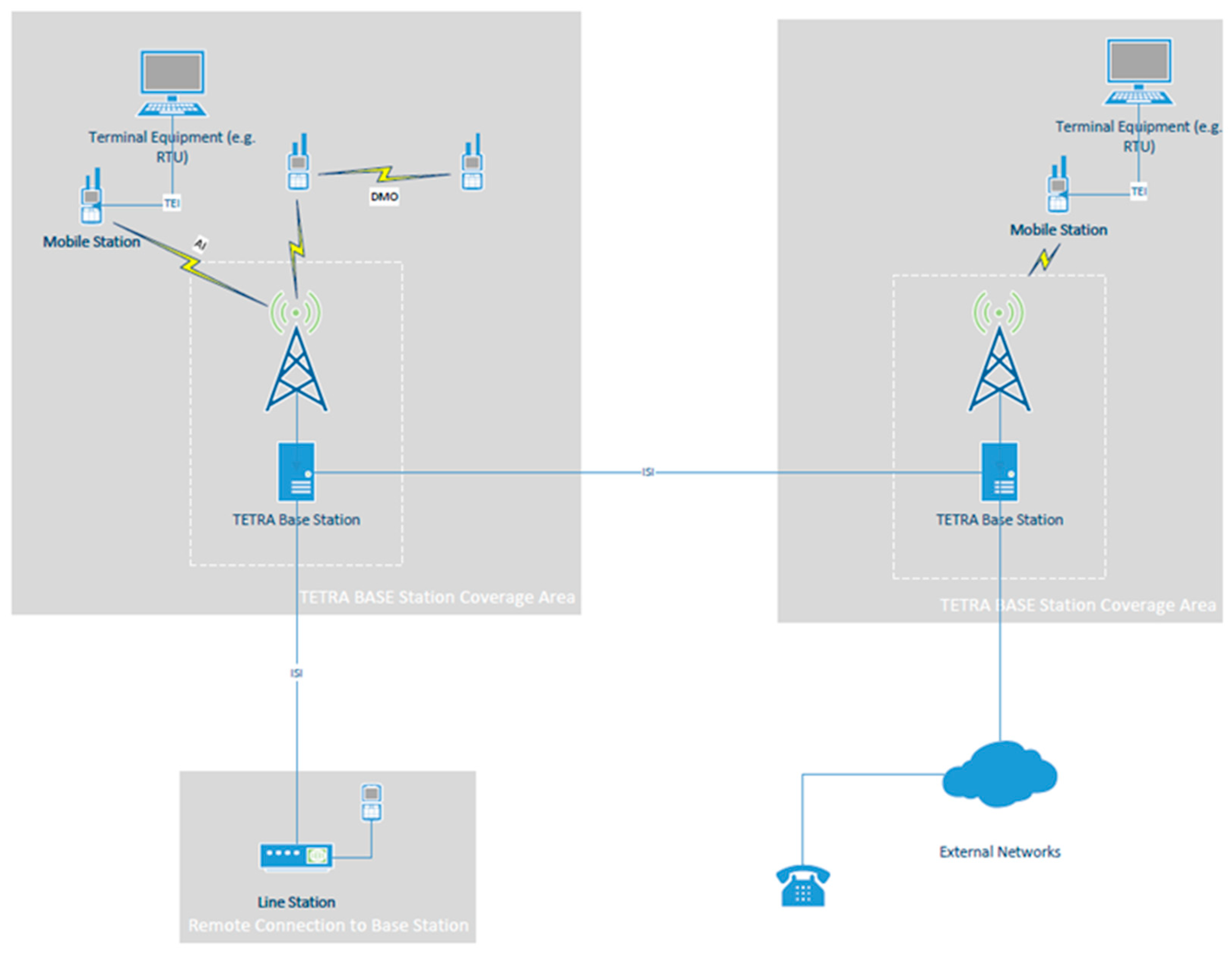
TETRA communication takes place over multiple interfaces. Communication between Mobile Stations and Base Stations, or other Mobile Stations takes place over the Air Interface. Direct communication between two mobile stations is referred to as Direct Mode Operation. TETRA intersystem communications on the same network between two or more Base Stations, or between Base Stations and Line Stations is accomplished through an ISDN and is managed by Network Management Unit.
Figure 1 is an illustration of the typical TETRA network Interfaces.
The main TETRA Interfaces in a typical TETRA Network are [
3]:
-
The Air Interface (AI): The Air Interface is a physical layer interface that provides communication between mobile stations and the base. The Air Interface supports two modes of operation.
- ◦
Direct Mode Operation (DMO): Direct Mode Operation allows for direct communications between mobile stations that are within range over the Air Interface.
- ◦
Trunked Mode Operation (TMO): Trunked Mode Operation is when two mobile stations communicate with each other through the Base Station. The Base Station in this case acts as a central channel controller which assigns channels automatically from a limited pool of available frequencies.
TETRA Inter-system Interface (ISI): The Inter-system Interface allows for communications between TETRA networks.
Terminal Equipment Interface (TEI): The Terminal Equipment Interface provides communications between the mobile termination point and Terminal Equipment within a mobile station.
2. Threat Model
Voice and data transmitted by TETRA radio systems is Air Interface Encrypted (AIE) to protect its confidentiality and integrity and prevent eavesdropping and man-in-the- middle type attacks. The original TETRA standard came with four (4) AIE encryption algorithms to accomplish this. In 2022, the European Telecommunications Standards Institute (ETSI) introduced three additional AIE algorithms to mitigate the risk that newer more powerful computers will soon be able to break the existing encryption algorithms [
4].
The AIE algorithms for TETRA are referred to as TETRA Encryption Algorithm (TEA) ciphers. TEA1 is for commercial use. This includes systems used in critical infrastructure across the globe. TEA2 is limited to European public safety organizations such as emergency services, military, and intelligence. TEA3 is for public safety organizations that are in EU friendly countries outside Europe. Like TEA1, TEA4 is for commercial use but is not commonly used. TEA5, TEA6 and TEA7 have been introduced in 2022. Even though the new TEA ciphers can be used to improve the security of new TETRA installations, it does not address the security of existing installations. Updating existing TERA systems will be an expensive undertaking and would require downtime to implement.
Although TETRA is an open standard, the encryption algorithms are a closely guarded secret that is only available to a select number of companies that have Non-Disclosure Agreements [
5]. Only recently, in November 2023, did the ETSI announce that the TETRA encryption algorithms will enter the public domain [
4]. The security-by-obscurity approach has prevented proper evaluation of the algorithms for potential flaws. According to Wired article [
6], researchers were able to extract and reverse-engineer the secret encryption algorithms by defeating a TETRA radio device protection.
The TEA1 stream cypher encryption keys are advertised as 80-bit long. Even by today’s standards, this is sufficiently long. A Blackhat USA 2023 conference presentation [
5] by Midnight Blue, a security research company, revealed that a secret “baked-in” [
6] key initialization feature reduces this from 80 to just 32 bits. While a 32-bit key would have been considered secure during the development of the standard back in the 1990’s, it can now be cracked in less than a minute. Midnight Blue was able to demonstrate this by intercepting a TETRA message and decrypting it using a high-powered graphics card in about a minute [
1]. The implication here is that a passive adversary within the area of TETRA radio coverage can exploit this secret vulnerability, intercept, decode and eavesdrop on the radio traffic.
A Technical report issued by the European Telecommunications Standards Institute in 1994 addressing TETRA security identifies a false base station scenario (Man-in-the-middle) as a possible TETRA security threat [
7] but does not identify the TEA1 encryption backdoor to carry out such an attack.
TETRA is used for Controller to RTU (Remote Terminal Unit) system communications in electrical substations as part of the SCADA WAN. These are considered critical for remote operations and need to be secured at the Electronic Security Perimeter to comply with NERC-CIP. In the case of a SCADA network, there is less emphasis on confidentiality (eavesdropping) and more on the availability and integrity of control data. It is conceivable, for example, that an active adversary carries out a man-in-the-middle attack by intercepting control system commands/feedback and altering it to disrupt the power grid operations.
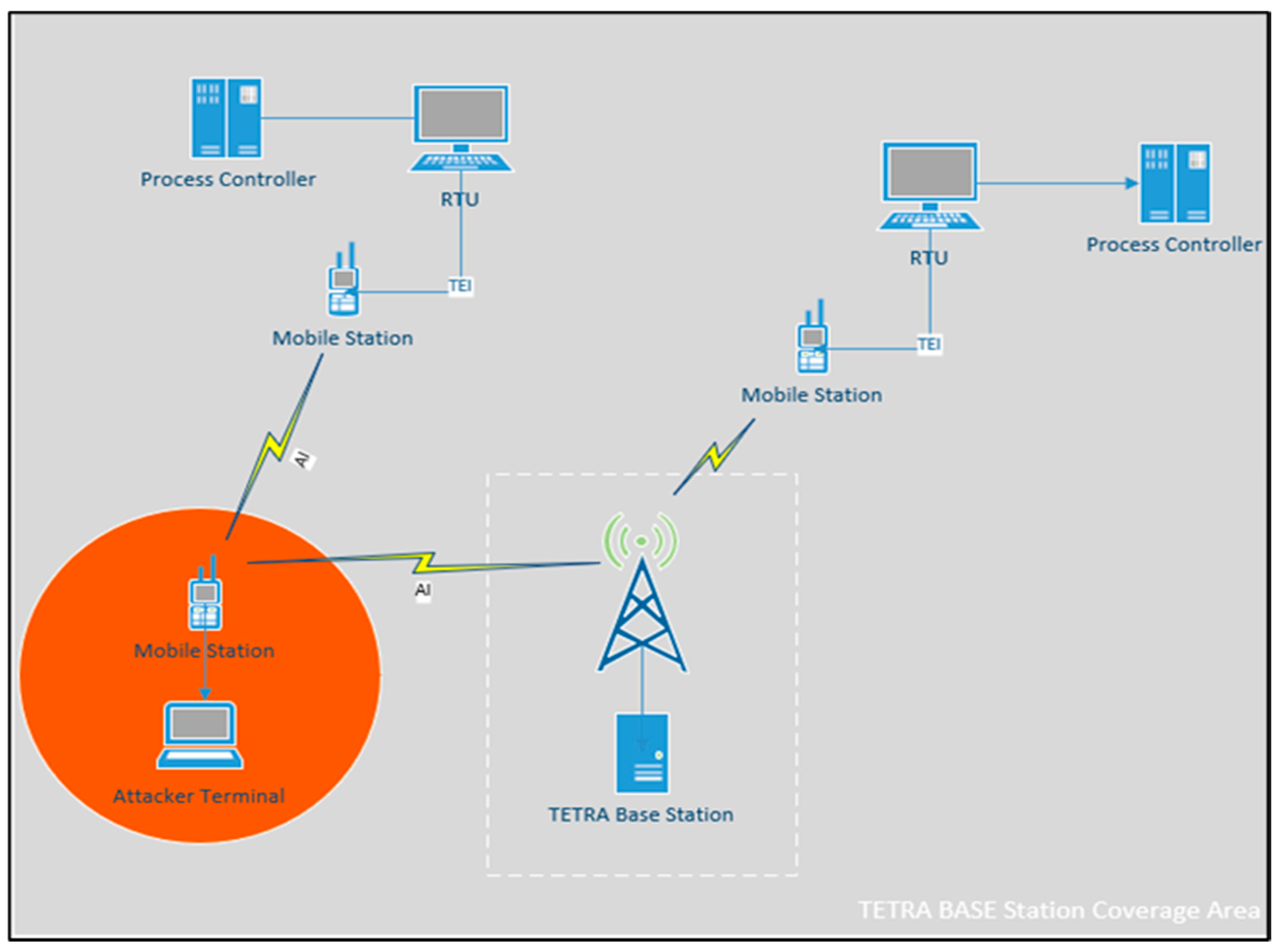
Figure 2 shows how such an attack can be carried out.
An active adversary can send unauthorized commands through the Air Interface by generating its own message, replaying a recorded message or by altering authorized messages. This can be accomplished by using another legitimate TETRA mobile station.
A more sophisticated attacker can reverse engineer the TETRA system and use their own transmitter to transmit commands at higher powers than those allowed by the FCC. This can be done to overpower the channel and impose their message on the receiver. This is known as the Capture Effect [
8].
Furthermore, Multiple-input and multiple-output (MIMO) directional techniques [
9] can also be employed to improve the quality of the channel between the attacker and the receiver by providing the attacker with power gain to overpower the channel. In this arrangement, multiple antennas are aligned in a certain way to broadcast signals at powers that are within the FCC limits. The combined effect of the directional antennas provides sufficient power gain and reduces the fading effect that results from the jamming signal.
3. Related Work
Published research on vulnerabilities associated with TETRA network authentication, such as “The Vulnerability Analysis and Improvement of the TETRA Authentication Protocol”, an IEEE conference paper published in 2010, does not address Air Interface Encryption (AIE) [
10]. Most published research addresses security from the network authentication perspective rather than the Air Interface Encryption. This can be attributed to the fact that the AIE algorithms are kept secret.
Perhaps this is the most challenging aspect of addressing this problem. TETRA encryption algorithms are a closely guarded secret that is only available to a select number of companies that have Non-Disclosure Agreements [
5]. Only recently, in November 2023, did the ETSI announce that the TETRA encryption algorithms will enter the public domain [
4]. Although the standard has been around since the 1990’s, there has been little evaluation and scrutiny of the encryption methods. There was also little motivation to address this back in the 1990’s because a 32-bit key was considered sufficiently long. This has changed as computing power capabilities have increased over the years.
A Technical report issued by the European Telecommunications Standards institute in 1994 addressing TETRA security identifies a false base station scenario (Man-in-the-middle) as a possible TETRA security threat [
7], but with no knowledge of the TEA1 encryption backdoor, it does not address how such an attack can be carried out.
The TEA1 vulnerability is not something that can be fixed with a simple firmware update since the secret feature to reduce the key to 32 bits is hardcoded in the device. TETRA also has no authentication for direct radio transmissions. Authentication only takes place when a radio is authenticated on a Tetra Network [
11].
Another IEEE paper on Exploring the human dimension of TETRA published in 2011 claims that TETRA was still considered to be a technically secure solution [
12]. Researchers have only recently been able to extract and reverse-engineer the secret encryption algorithms by defeating a TETRA radio device protection [
5]. These results have not been published [
13].
With a vulnerable encryption and no Air Interface authentication, the only other known practical means to secure this data traffic are:
4. Solution
4.1. Principles of Friendly Jamming
Friendly Jamming is a strategy where nodes in an RF system, other than the legitimate transmitter and receiver, are utilized to produce white noise which interferes with the ability of an eavesdropper to decode the signal. It is meant to degrade the eavesdropper’s link and improve physical security. By design, only the legitimate receiver would be able receive the transmitted signal through signal nullifying techniques [
14]. To receive the signal at a legitimate receiver, transmitters within the coverage area of the receiver are utilized to send out signals to nullify the Frequency Jammed signal.
The theory behind physical layer security is based on the Gaussian Wiretap Channel and Secret Capacity works by Wyne [
15]. A wiretap channel is a channel that introduces noise to the system to maximize the rate at which information is transmitted reliably to a legitimate receiver while minimizing the wire-tapper’s ability to learn about the message. In a way this is analogous to cryptography where the wiretapper is aware of the encoding and decoding scheme but is not able to decode the signal due to the Gaussian noise introduced in the wire-tap channel. The Secret Capacity of the channel is simply the difference between the main channel capacity (between the legitimate transmitter and receiver) and the wiretap channel capacity (between the transmitter an adversary).
Eavesdropping and man-in-the-middle attacks are typically addressed through Public Key cryptography. Friendly Jamming is a different approach that addresses the security at the physical layer. The advantage of using Friendly Jamming as an alternative method is that it allows for implementing a solution without relying on Tetra’s secret and vulnerable AIE. It does not require making modifications to the TETRA devices. Adding end-to-end encryption modules to each radio device is an expensive option which would require taking the devices out of service.
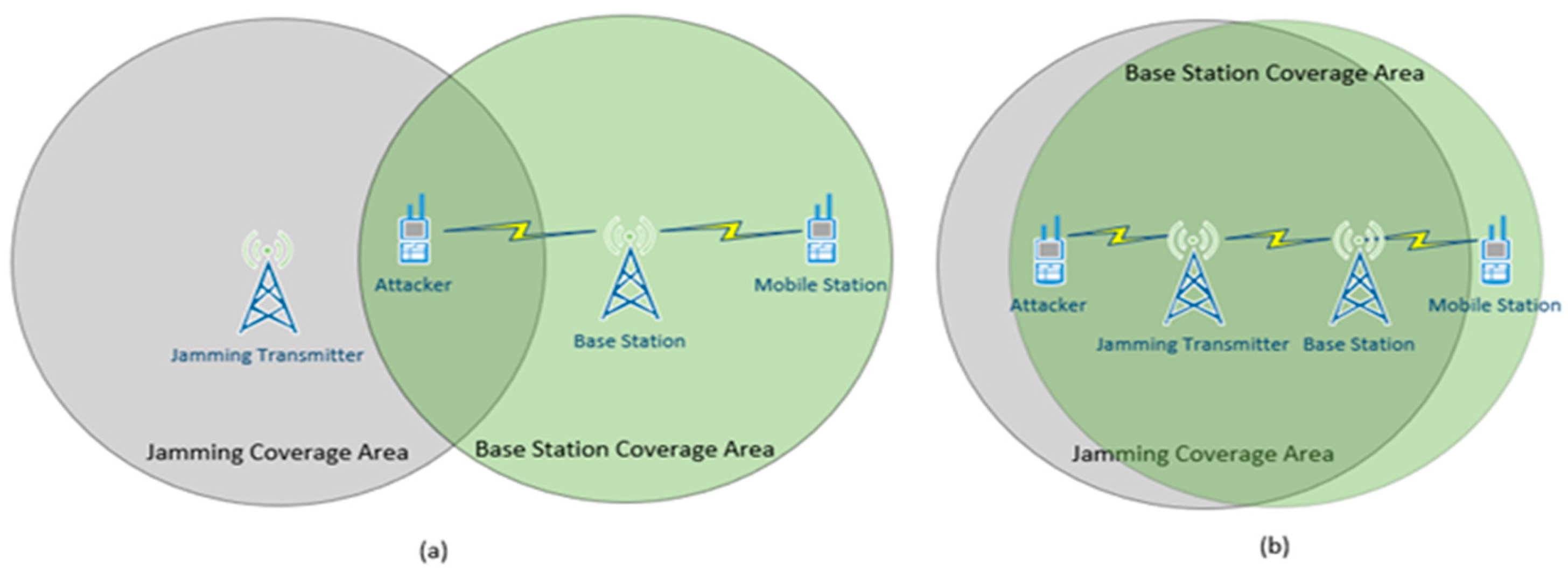
Figure 3 illustrates a simplified concept of friendly jamming given two different physical arrangements to achieve security. In the arrangement (a) the attacker is inside the Jammer’s coverage area while the transmitting device and legitimate receiver are outside and can communicate with each other. In this scenario the ability to jam the attacker’s channel is dependent on their location. This is a major limitation.
In arrangement (b) the Jamming transmitter and the legitimate transmitter are located close to each other. Close is defined as less than half the wavelength of the legitimate signal’s carrier frequency. Both the legitimate transmitter and the Jamming transmitter are inside the jamming coverage area. In this case an attacker within range of the Base Station is also within range of the Jamming Transmitter. The signal will be received at the legitimate Mobile station because the mobile station is located outside the Jamming Transmitter’s Coverage area while remaining within the Base station’s coverage area.
The methods described above are location dependent. An attacker outside the jamming transmitter’s coverage area and inside the Base Station’s coverage area will be able to intercept and decode the communication.
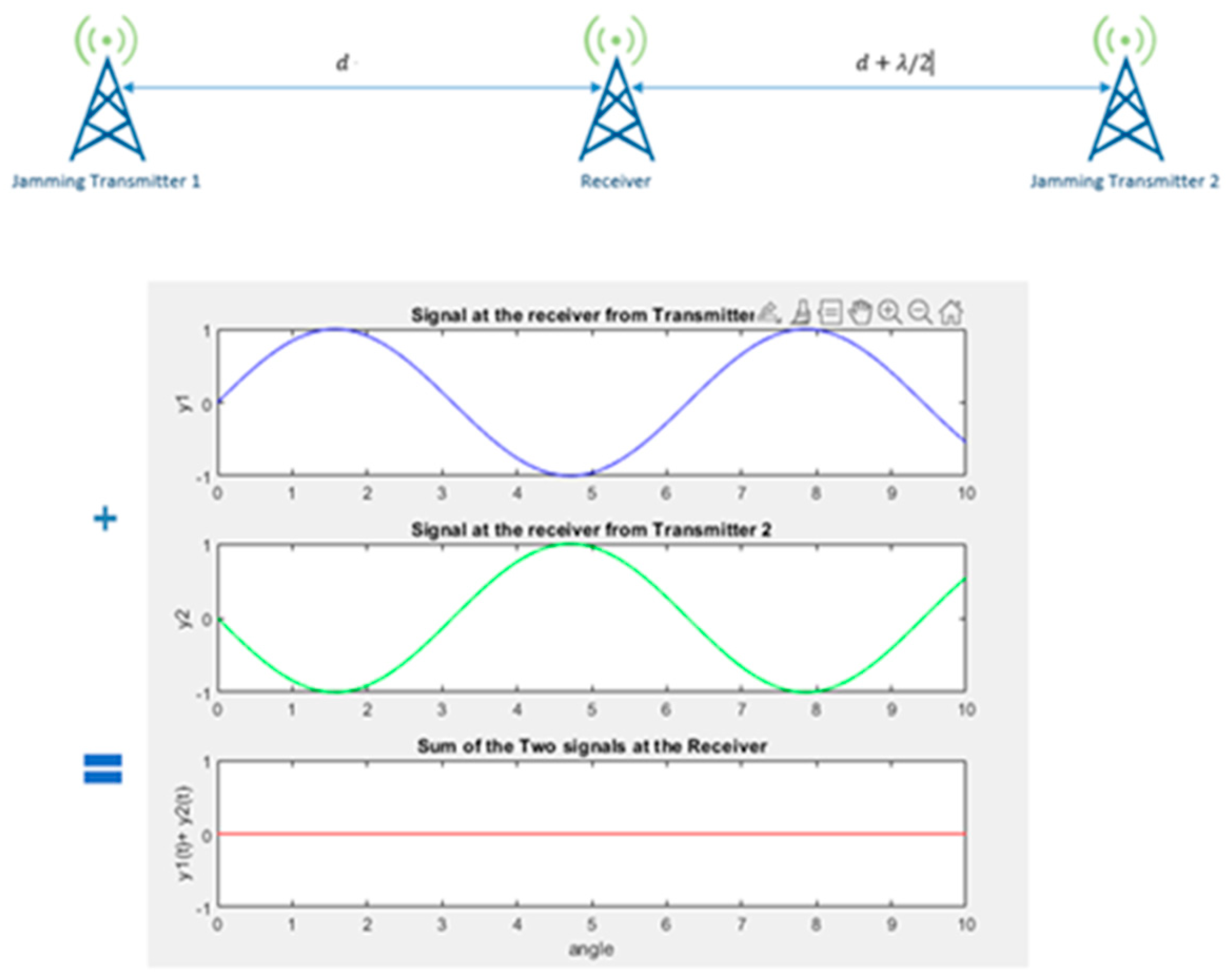
A more sophisticated approach to implementing friendly jamming is to utilize antenna nullifying techniques. Antenna cancelation is based on the principle of the constructive and destructive interference patterns of propagating waves over space [
15]. In this arrangement in
Figure 4 two jamming transmitters are placed at a distance d and distance
from the legitimate receiver.
is the wavelength of the transmitted jamming signal. The same jamming signal is transmitted by both transmitters. The phase offset between the two received signals due to the layout will result in the jamming signal destructively cancelling each other out at the receiver.
Tetra radios operate in the 400 MHz range. The wavelength is in the 0.75 meters range. The simplified antenna cancellation technique described above requires that the jamming antennas are placed with precision to successfully cancel out the jamming signal at the receiver. This imposes rigid positioning requirements which can make the implementation difficult and inconsistent.
4.2. Solution Using Friendly Jamming
This review examines a novel approach presented in [
16] that utilizes Frequency Jamming techniques to address the security of Implantable Medical Devices (IMD’s), draws parallels between these and the TETRA radio system, and applies the same concept to addressing and solving the TETRA AIE vulnerability. The physical layer solution addresses a threat model that is like the TETRA threat model described in
Section 2 of this paper.
Like TETRA’s threat model, IMD’s are wireless devices and can be exploited through the Air Interface to compromise their confidentiality or to send unauthorized commands. TETRA and IMD’s also share a similar constraint when implementing a solution; it is highly desirable to make improvements to their security without having to modify the device. Taking IMD’s out of service is risky and physical modifications requires surgery with possible complications.
The proposed solution utilizes an external jamming device, like the one referred to as the shield in [
16], which jams signals being transmitted to and from a TETRA station to prevent all other RF systems from decoding them while having the ability to decode them itself. The device tailored for the TETRA system will be referred to as the TETRA shield. In a sense the TETRA shield device acts as a proxy that only allows communications to and from the TETRA station through itself. The device has no physical interfaces with the tetra system outside of the air interface. It is an external device that is placed near a TETRA station in a physically secured location such as a substation.
In a TETRA system the mobile station sends and receives data through the TETRA shield instead of doing this directly through the base station. The TETRA shield acts as a proxy between the mobile station and the base station or other mobile stations (Direct Mode Operation).
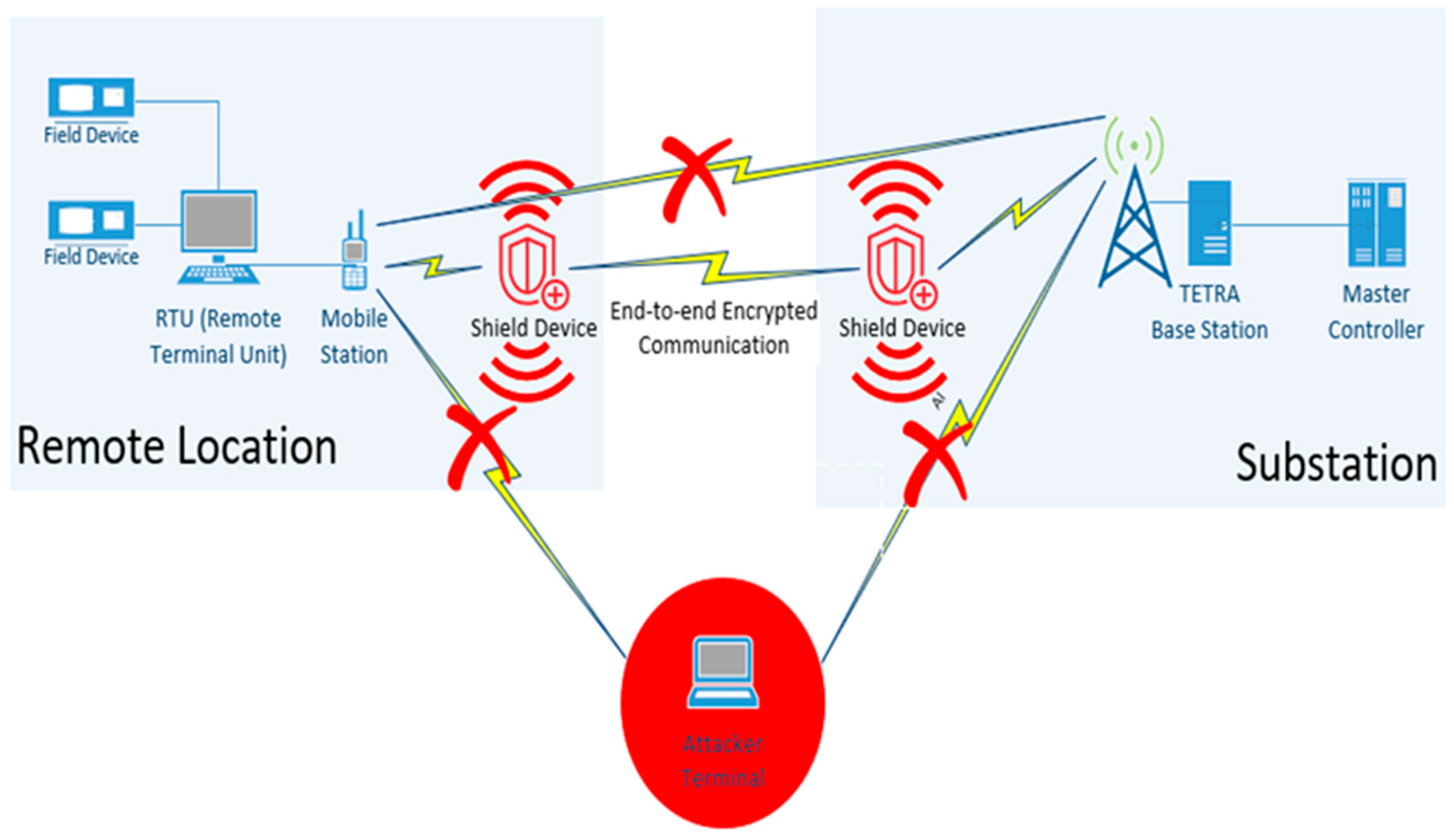
Figure 5 shows the high-level implementation of the shield solution in a TETRA system used.
The TETRA system in
Figure 5 uses a TETRA mobile station to exchange SCADA data with an RTU in a remote location. The RTU exchanges data and receives commands from a central master controller which is co-located with a TETRA base station inside a substation. Two TETRA shield devices are used in this scenario; one is placed near the RTU and another one near the base station. The TETRA shield devices at both locations exchange data with each other over the air interface using standard end-to-end encryption techniques. All other communications between the Tetra mobile and base stations are jammed.
The shield continuously listens for transmissions from the TETRA station and jams them to prevent eavesdroppers within the coverage area from decoding them. The received signal is then decoded by the shield and transmitted to another shield near the base station using standard end-to-end cryptographic techniques. The shield also continuously listens for unauthorized transmissions addressing the TETRA station and jams them in case an attacker attempts to send an unauthorized command to an RTU through the mobile station.
4.3. TETRA Shield Design
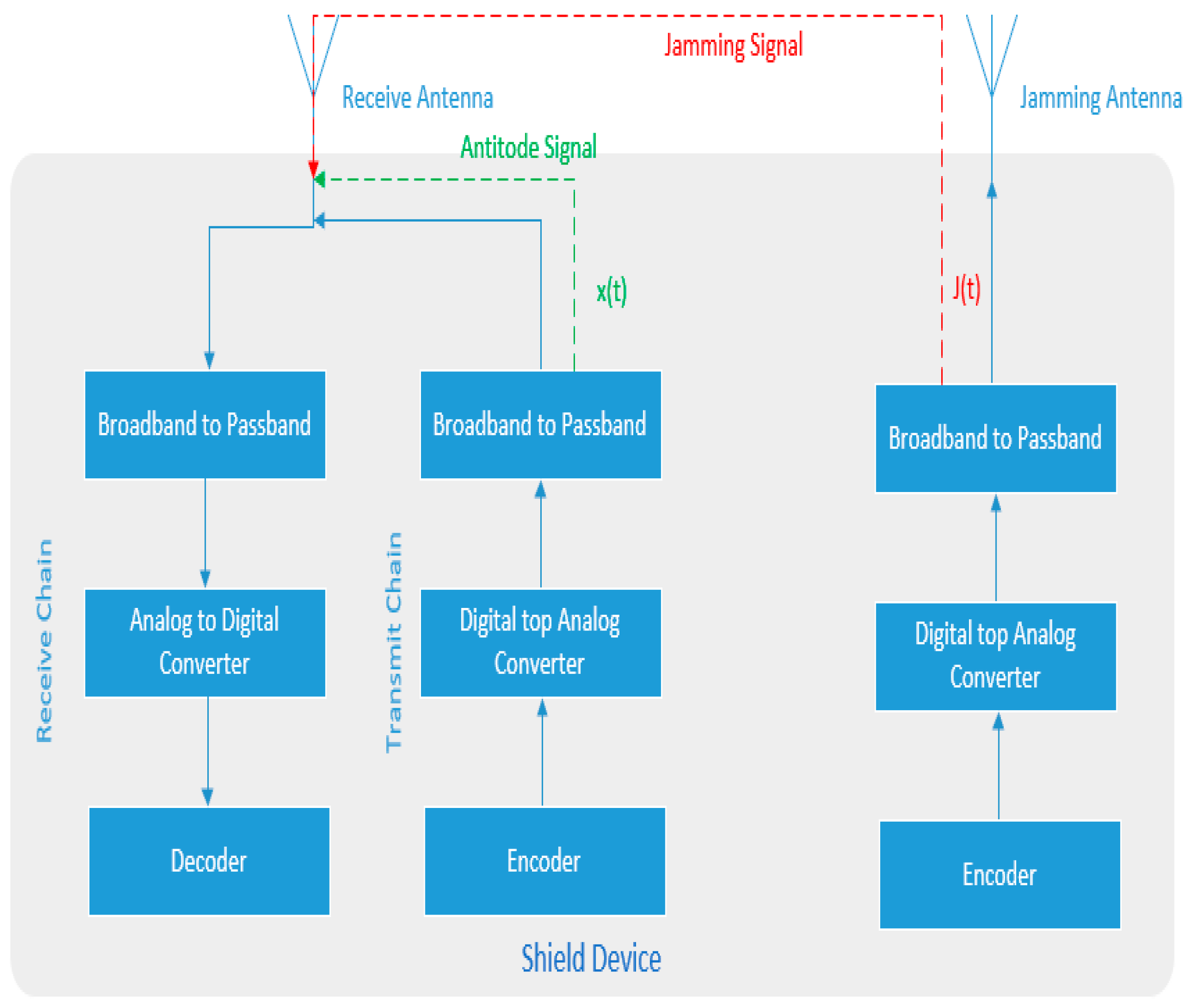
The TETRA shield is a full duplex system. It is equipped with two antennas. One antenna transmits the jamming signal, and the other is the receive antenna. The receive antenna is connected to both receive and transmit chains [
16]. The receive chain receives the jammed signal from the TETRA station and simultaneously transmits a nullifying signal through the transmit chain to decode the received signal. This creates a self-looping channel at the receive antenna where the received jammed signal is decoded simultaneously using the same device.
The TETRA shield device scheme does not have the same rigid positioning requirements for implementing Antenna Cancellation techniques such as the ones discussed in [
15]. This is accomplished by placing the jamming antenna and an antidote signal transmit/receive antenna on the shield device. Although there are no rigid requirements for the placement of the shield device from the TETRA base station it is recommended to place the shield at a significantly less than
from a TETRA Station. This is to protect against directional and MIMO attacks [
9]. Another limitation imposed by the TETRA shield design is that the attacker must be located further away from the Tetra base station than the shield by at least 0.2 meters [
16]. This is not an issue for a physically secured substation or control room. A physically secured shield and Tetra station locations is a reasonable assumption for this design.
The TETRA shield is a full duplex device which allows for receiving the signal and transmitting the antidote simultaneously. The shield uses its knowledge of the jamming signal, wireless channels, and the self-looping chain to compute the appropriate antidote signal that is required at the receiver.
Figure 6 below shows the basic building blocks for the TETRA shield device [
16].
In the arrangement in
Figure 6 the transmit channel computes antinode signal
based on its knowledge of the transmitted jamming signal
, the self-looping channel coefficient
, and the jammer to receiver channel coefficient
. The TETRA shield estimates the channel coefficients using channel estimation techniques [
17]. The shield can estimate this without using a pilot symbol since both receiver and the transmitter are on the same device, and both are known. Given that the transmitted signal at the TETRA shield receiver is
, the signal at the receive antenna,
, can be computed as:
The antidote signal
can then be computed such that it cancels the jamming signal:
Solving for
to satisfy this condition in equation (1):
An important premise for the design is that the jamming signal
is only cancelled at the TETRA shield device receive antenna. To ensure this is the case the TETRA shield Receive, and Jamming antennas are placed close together. To cancel the jamming signal at location
from the shield:
Since the distance between location
and the TETRA shield is much larger than the distance between the Receive and Jamming antenna it can be assumed that:
To be able to cancel the jamming signal at location
the following condition must be satisfied:
The TETRA shield’s self-looping channel is connected directly through a short wire therefore will be significantly smaller than the air interface channel . This makes the above condition infeasible to satisfy for the TETRA Shield. Therefore, we can safely assume that the jamming signal cannot be cancelled out at another location .
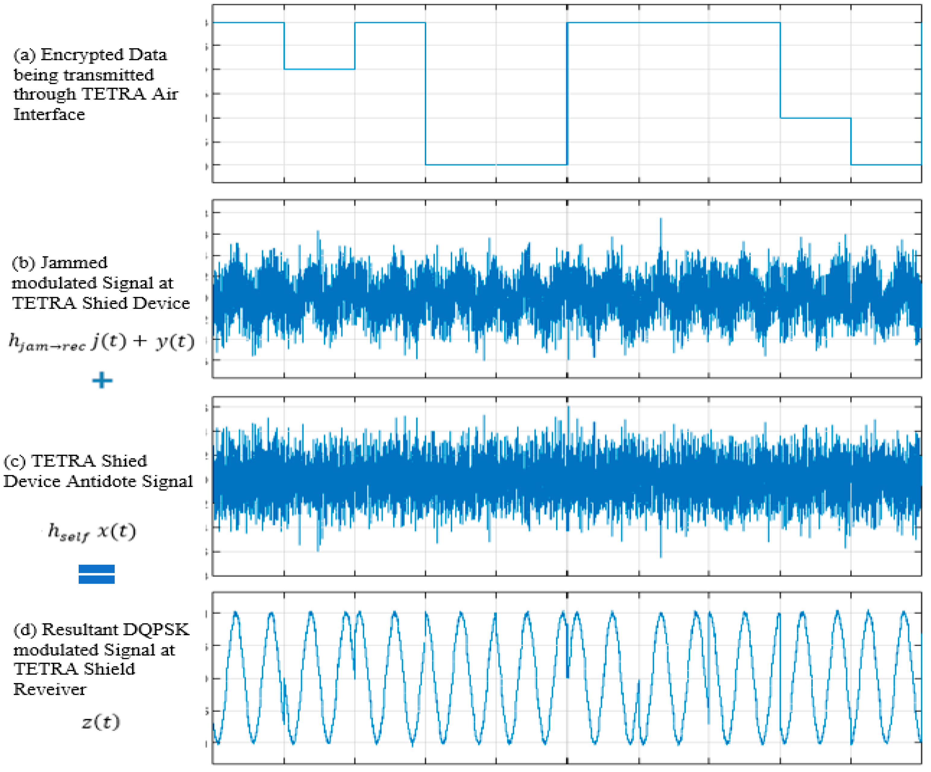
The graphical illustration in
Figure 7 demonstrates the basic principles of the TETRA shield. A TETRA station transmits encrypted data as shown in
Figure 7 (a) using the DQPSK (differential quadrature phase shift keying) method. The signal is then jammed using the TETRA shield through the shield’s jamming antenna. The jammed signal at the receiver is shown in
Figure 7 (b). The jamming signal is simultaneously cancelled out at the TETRA shield’s receive antenna using the calculated antidote signal in
Figure 7 (c). It is important to note that the signal is only cancelled at the TETRA Shield device antenna. Other receivers in the vicinity will receive the jammed signal, which cannot be decoded. The resultant signal at the TETRA shield’s receive antenna is the DQPSK modulated waveform, shown in
Figure 7 (d), which can then be demodulated and decoded by the TETRA shield device.
5. Evaluation
The TETRA shield solution and its limitations shall be evaluated in this section. The TETRA solution proposed in this paper does not adequately address: (i) new developments in jamming signal cancellation techniques and (ii) The use of high-powered data sources (much higher than jammer power) to carry out attacks and overwhelm the jammer and other legitimate sources.
5.1. Jamming Signal Cancellation Techniques
The work performed in [
16], which is used as the basis for the shield implementation for TETRA in this paper, does not adequately evaluate the use of multiple devices by an attacker. The authors in [
16] assert that the shield device can be protected from MIMO attacks by placing the shield significantly less than half a wavelength away from the data source. A paper on the Limitations of Friendly Jamming for Confidentiality [
8] challenges the notation that proximity alone is enough to protect against confidentiality attacks.
A new type of MIMO attack is introduced in [
8] which uses multiple devices to recover confidential data from distances of up to 3 m away from the data source. In this setup the jammer (Shield device) is placed a few centimeters away from the data source. The authors performed experiments using frequencies like those used by TETRA (402 – 405 MHz) and were able to demonstrate that an attacker can successfully recover confidential data from up to 3 m away from the data source. To simulate an IMD’s environment (human flesh) they placed the data source in a layer of ground beef and bacon which reduced the distance to 2 m. The attacker does not need to recover the full message, instead they can reconstruct the full message from individual fragments based on their knowledge of the system.
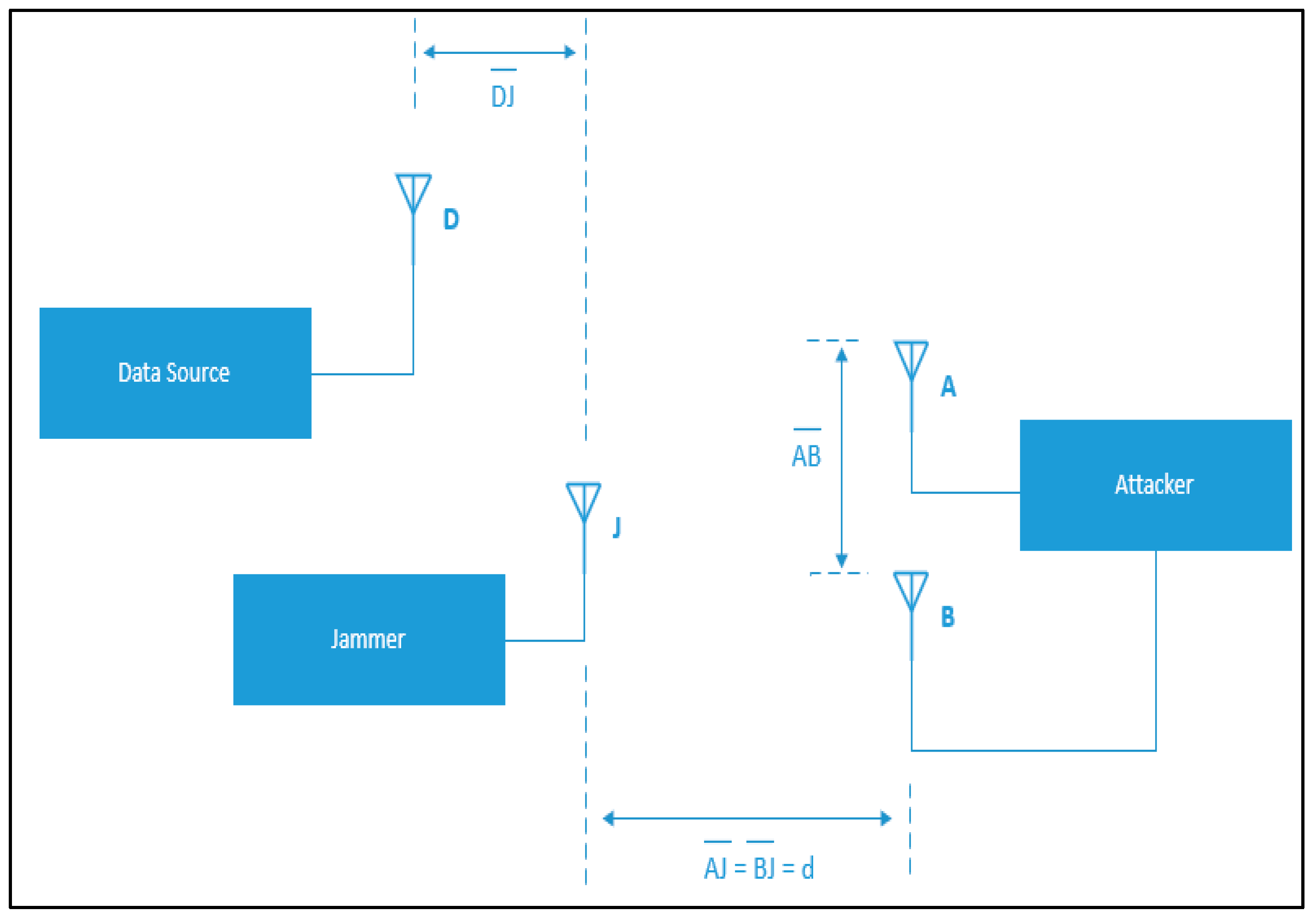
The setup of the MIMO attack in [
8] is shown in
Figure 8. It requires that an attacker is located at a distance that is at least 20 cm further from the data source than the jamming device [
16]. The attacker is equipped with two antennas A and B. The antennas are placed at the same distance from the jamming device J (
) but are not at the same distance from the data source D (
). The difference in distance between the attacker’s antennas and the data source will result in a phase offset at the data source. We can assume that to be
radians (approximately 19 cm).
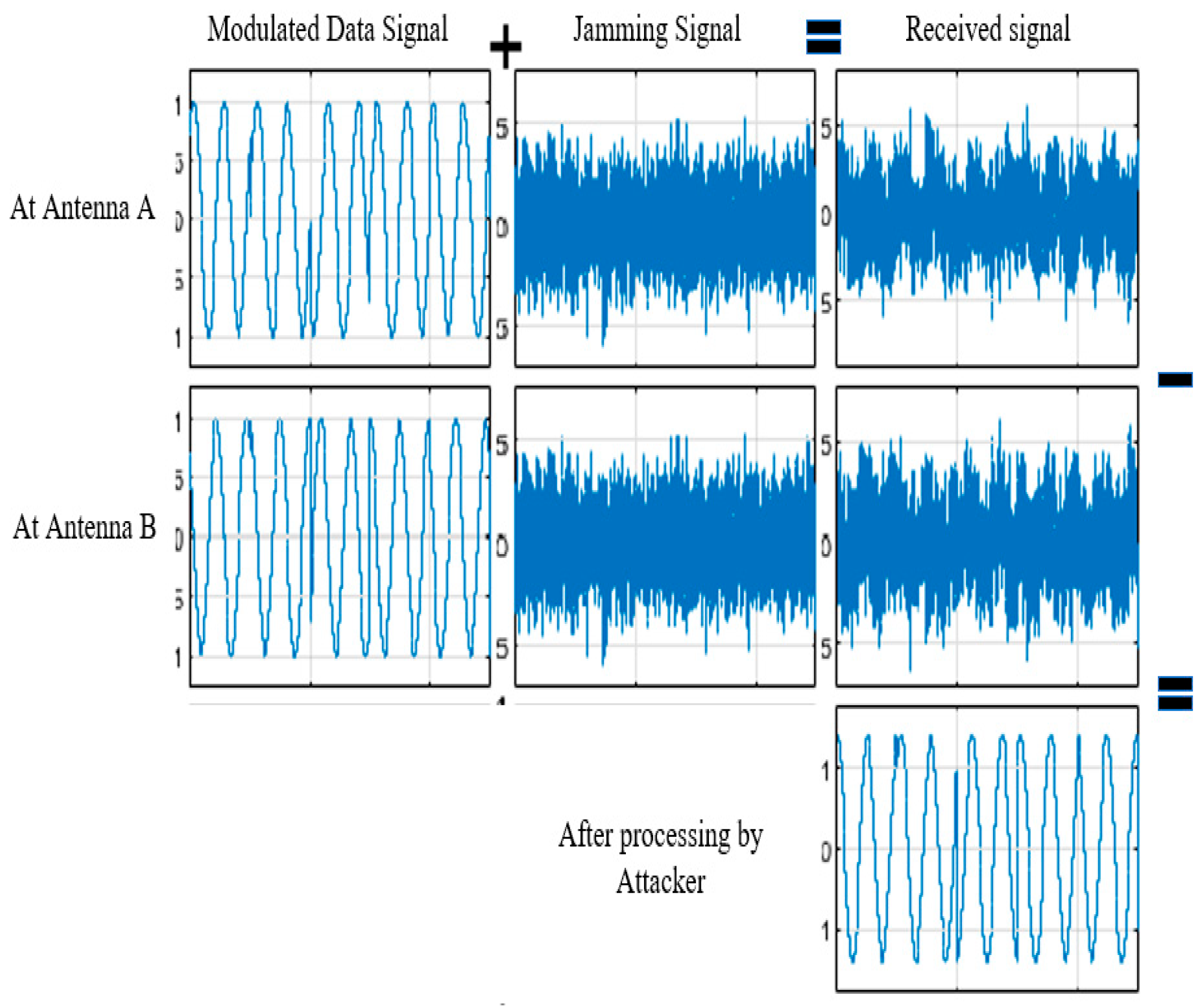
The basic principle behind the attack is that an adversary can remove the jamming component by subtracting the signals received at both antennas. The results of a simplified MATLAB simulation in
Figure 9 demonstrate this principle.
The physical setup in
Figure 8 was used in [
8] to evaluate the effectiveness of the attack at different distances from the jammer. In the experiment the distance
was kept at 15 cm and three different configurations between the attack antennas
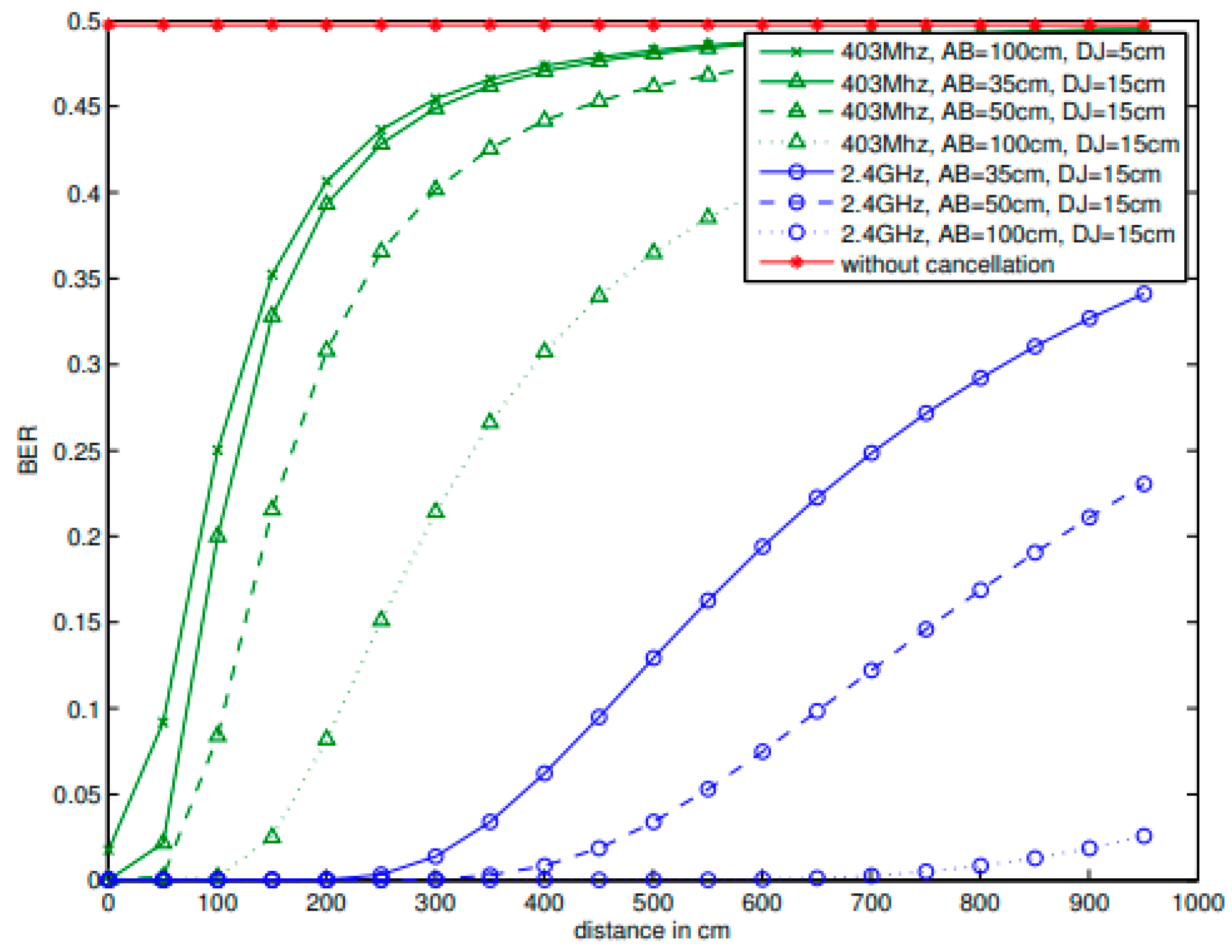
were used. The attacker’s antennas were placed at 35, 50 and 100 cm apart. The bit error rate (BER) was used to measure the effectiveness in recovering the original signal. The results in
Figure 10 are copied from [
8] and summarize the results of their experiment.
The results in
Figure 10 show that without the use of the MIMO jamming cancellation technique the BER at the attacker antenna is 50% even at very short distances. This demonstrated the effectiveness of the frequency jamming techniques used for the development of the shield device. The attacker in this case is not able to recover the transmitted data.
When the described MIMO jamming cancellation technique is used the authors show that at the largest separation, where is set at 100 cm, there is an improvement in performance and that the signal can be recovered at distances as far away as 2 meters.
This limitation can be mitigated for TETRA systems by introducing strict physical security parameters around these systems. A substation is a good example in this case. To be NERC compliant, even at a low impact site, requires securing the physical perimeter. Securing a physical parameter > 3m from a TETRA base station is not difficult to achieve.
5.2. Shield Device Application in IMD’s
The shield device [
16] was evaluated with commercially available IMD’s by placing the IMD and the shield very close to each other (< 20 cm) in a fixed location and experimenting with 18 different adversary locations between 20 cm to 30 m from the IMD. The Jamming device power was set at 20dB above that of the IMD’s. It was found that this power setting allowed for the shield’s own receive antenna to reliably decode messages while effectively jamming external messages.
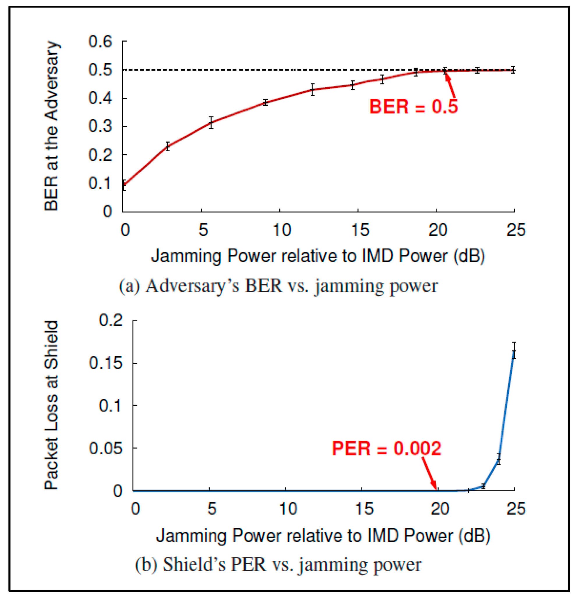
Figure 11 copied from [
16] shows the relationship between jamming power, BER at the adversary and packet loss at the shield. There is a tradeoff between the BER that can be achieved at an adversary receiver and packet loss at shield. 20 dB is seen as the optimal point to maximize BER and minimize packet loss at the shield. When jamming power is set at 20 dB above the power received from the IMD a 50% BER is achieved at packet loss rate (PER) of only 0.2% at the shield.
The results using this setup show that a passive eavesdropper at all eighteen test locations has a BER of 50%. Any decoding at this rate is no more effective than a random guess. When these settings are used to evaluate the effectiveness of the shield device against an active adversary it was found that the programmer was not able to get a response from the IMD even at distances as close as 20 cm.
A limitation imposed by the TETRA shield design is that the attacker must be located further away from the Tetra station than the shield by at least 20 cm [
16]. This is not an issue for a physically secured substation or control room.
The results in
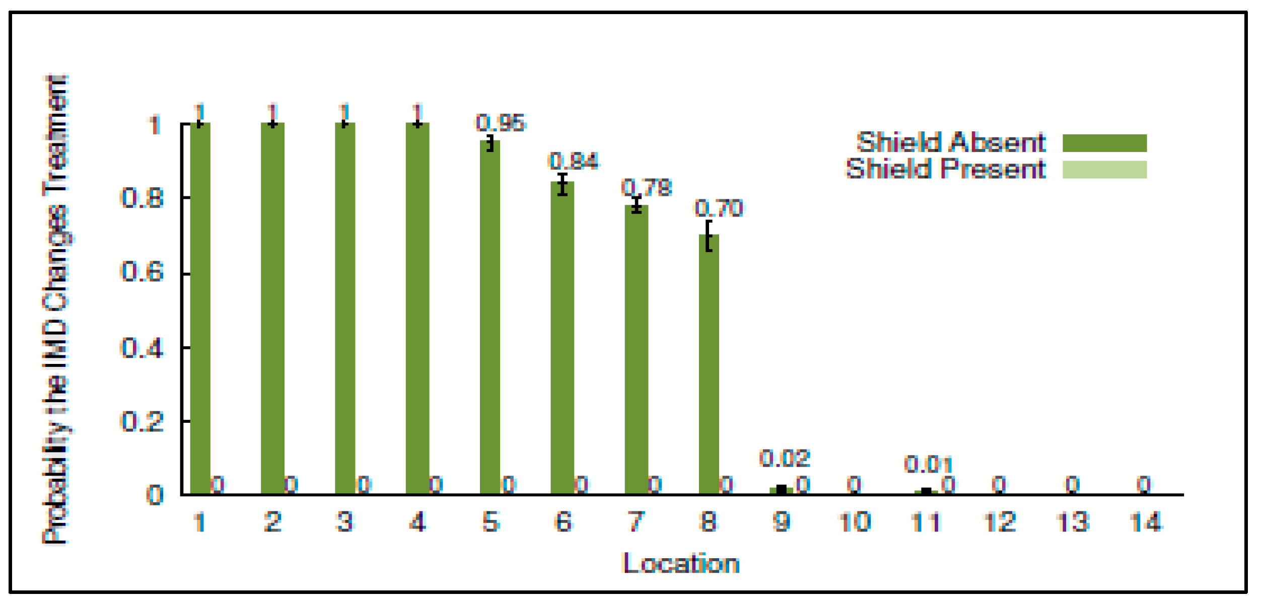
Figure 12 give a good indication of the potential effectiveness of the TETRA shield device in protecting against an active adversary when placed at different distances (20 cm to 30 m) from a base station. In this case the adversary attempts to send unauthorized commands to an IMD using an off the shelf programmer. The results in
Figure 12 illustrates the probability of successfully carrying out an attach with and without the shield. The results show that the shield device is quite effective at reducing the probability of an adversary to successfully issue an unauthorized command to the IMD.
An important consideration for the results presented in [
16] is that they are specific to the shield design using IMD devices. These are typically low power devices relative to a TETRA mobile station. Although the carrier frequency for both systems is similar, they have different waveforms. IMD’s employ Frequency Shift Keying (FSK) techniques rather than the DQPSK techniques employed by TETRA. This will result in different estimated jamming efficiencies and BER rates. Future work on the TETRA shield device should experimentally evaluate the performance of the TETRA Shield using TETRA transmitters and receivers which employ DQPSK coding and decoding techniques.
5.3. Use of Sophisticated High-Power Transmitters
An adversary can utilize sophisticated high-powered transmitters to overpower the channel and impose their message on the receiver. If an attacker transmits at much higher powers than those permitted by the FCC, they can significantly reduce the jamming device’s power relative to the attacker’s signal and thus allow the attacker’s transmitter to overwhelm that of the jammer at a TETRA receiver.
The shield device in [
16] was tested with a transmitter at 100 times the shield’s power. The results are illustrated in
Figure 13. It was found that at such transmit powers and without using the shield device, an attacker was able of get responses from the IMD at distances of up to 27 meters. When the shield was turned on, the adversary needed to be much closer, less than 5 m [
16], to get responses from the IMD. This indicates that the presence of the shield significantly improved the ability to defend against such attacks.
Even though the shield makes it more difficult to carry out high powered attacks, it doesn’t fully address them. The impact on the shield’s effectiveness at transmit powers that are 200 times, 500 times, or larger has not been evaluated. An acceptable distance varies from one application to another. In the case of a substation for example 5m or 10m could very well be within the physical boundary of the substation and can be acceptable but this would not be acceptable for an IMD where 5 to 10 meters could mean someone can carry out an attack from the next room. This would be a great area to explore in future works on this device.
6. Future Work
The evaluation presented in this paper is done on IMD devices. Although the concept for both IMD’s and the TETRA shield are very similar, future work for this project should build and evaluate a TETRA specific shield device. Both TETRA and IMD’s use carrier frequencies in the 400 MHz range, but the bit rates are different. An evaluation of different TETRA bit rates ranging from 28.8 kbits/s to 500 kbits/s [
18] should be considered. Another consideration is that TETRA uses DQPSK to modulate the digital signal for transmission while the evaluated IMD’s use FSK (Frequency Shift Keying). These factors in addition to the fact that TETRA transmit powers are significantly higher than those of IMD’s will have an impact on the probability estimates and resulting BER rates.
Even though the shield makes it more difficult to carry out high powered attacks, it doesn’t fully address them. The impact on the shield’s effectiveness at transmit powers that are 200 times, 500 times, or larger has not been evaluated. An acceptable distance varies from one application to another. In the case of a substation for example 5 or 10m could very well be within the physical boundary of the substation and can be acceptable but this would not be acceptable for an IMD where 5 to 10 meters could mean someone can carry out an attack from the next room. This would be a great area to explore in future works on this device.
Recent work on reassessing frequency Jamming efficiencies [
19] reveals that the works used for evaluating the shield’s effectiveness have overestimated the jamming efficiency. The paper [
19] rebuilds the secrecy capacity model to take into consideration a non-stationary channel, where the effective transmission bandwidth changes with time, to calculate jamming efficiency. An important contribution of the paper is that BER rates for Friendly Jamming systems can be significantly improved by using a custom designed jamming waveform rather than Gaussian White Noise. Future work on the TETRA Shield’s design should consider and re-evaluate the TETRA Shield using this type of jamming waveform rather than Gaussian white noise.
An important area to evaluate and expand on in future works are the policy and compliance aspects of the TETRA Shield implementation. Using the term jamming makes this a sensitive topic since the FCC prohibits the use of Jamming devices. Further in-depth analysis of the laws and precedence is required to ensure the TETRA Shield is compliant and adheres to FCC regulations.
7. Conclusion
This paper presents and addresses recently discovered TETRA AIE vulnerabilities. The TEA1 stream cypher encryption keys are advertised as 80-bit long. Even by today’s standards, this is sufficiently long. A Blackhat USA 2023 conference presentation [
5] by Midnight blue, a security research company, revealed that a secret “baked-in” [
6] key initialization feature reduces this from 80 to just 32 bits. While a 32-bit key would have been considered secure during the development of the standard back in the 1990’s, it can now be cracked in less than a minute.
This review examines a novel approach presented in [
16] that utilizes Frequency Jamming techniques to address the security of Implantable Medical Devices (IMD’s), draws parallels between these and the TETRA radio system, and applies the same concept to addressing and solving the TETRA AIE vulnerability. This is followed by an evaluation of the solution.
The proposed solution in this paper utilizes an external jamming device which jams signals being transmitted to and from a TETRA station to prevent all other RF systems from decoding them while having the ability to decode them itself. The device tailored for the TETRA system is referred to as the TETRA shield.
The TETRA shield is an external device to the TETRA RF system. It does not require changes and updates to the TETRA system, or an understanding of the unpublished AIE algorithms to implement. The other known options that are available to address this problem are:
Switching from TEA1 to another TEA encryption algorithm that is available for commercial use. This would require system-wide changes at the device level.
Adding an end-to-end encryption module. This is an optional feature that is used in very special cases. It requires installing additional modules.
Both above options are expensive and require outages to implement. The TERA Shield offers a scalable solution that does not require outages to make system and device level changes to operational systems.
References
- INCIBE (National cybersecurity institute), “Cybersecurity in TETRA networks study,” MAR 2023. Retrieved SEP 3rd, 2023, from https://www.incibe.es/sites/default/files/2023-05/INCIBE-CERT_CYBERSECURITY_IN_TETRA_NETWORKS_STUDY_2023_v1.0.pdf.
- Shuwen Duan, “Security Analysis of TETRA,” Master’s Thesis, Norwegian University of Science and Technology, JUN 2013.
- Carlo Meijer, Wouter Bokslag and Jos Wetzels, “All Cops Are Broadcasting: Breaking TETRA After Decades in the Shadows,” Blackhat USA 2023 conference presentation by Midnight blue, AUG 2023. Retrieved AUG 27th, 2023, from https://www.blackhat.com/us-23/briefings/schedule/#all-cops-are-broadcasting-breaking-tetra-after-decades-in-the-shadows-31807.
- Jessica Lyons Hardcastle, “Bug hunters on your marks: TETRA radio encryption algorithms to enter public domain,” The Register article, NOV 2023. Retrieved NOV 20th, 2023, from https://www.theregister.com/2023/11/14/tetra_encryption_algorithms_open_sourced/.
- KIM ZETTER, “Code Kept Secret for Years Reveals Its Flaw—a Backdoor,” WIRED article, JUL 2023. Retrieved AUG 27th, 2023, from https://www.wired.com/story/tetra-radio-encryption-backdoor/.
- Lewin Day, “DID TETRA HAVE A BACKDOOR HIDDEN IN ENCRYPTED POLICE AND MILITARY RADIOS?,” HACKADAY Article, JUL 2023.
- Yong-Seok Park, Choon-Soo Kim and Jae-Cheol Ryou, “The Vulnerability Analysis and Improvement of the TETRA Authentication,” IEEE 2010 The 12th International Conference on Advanced Communication Technology, APR 2010.
- Nils Ole Tippenhauer, Luka Malisa, Aanjhan Ranganathan and Srdjan Capkun, “On Limitations of Friendly Jamming for Confidentiality,” IEEE Symposium on Security and Privacy, MAY 2013.
- S. Leung-Yan-Cheong and M. Hellman, “The Gaussian Wire-tap Channel,” IEEE Transactions on Information Technology, JUL 1978.
- Nico Pieter Fouché and Kerry-Lynn Thomson, “Exploring the human dimension of TETRA,” IEEE 2011 Information Security for South Africa conference, SEP 2011.
- ETSI Technical Report ETR 086-3, “Trans European Trunked Radio (TETRA) system; Technical requirements specification; Part 4: Security aspects,” JAN 1994.
- Carlo Meijer, Wouter Bokslag, and Jos Wetzels, “All cops are broadcasting: TETRA under scrutiny,” Proceedings of the 32nd USENIX Security Symposium, Aug 2023.
- Mark. M. Adams, “Improving Security for Future Wireless Networks Through Friendly Jamming,” Master’s Thesis, The University of British Columbia, MAY 2011.
- Capture Effect. In Wikipedia. Retrieved SEP 16th, 2023, from https://en.wikipedia.org/wiki/Capture_effect.
- Jung Il Choi, Mayank Jain, Kannan Srinivasan, Philip Levis and Sachin Katti, “Achieving Single Channel, Full Duplex Wireless Communication,” Proceedings of the sixteenth annual international conference on Mobile computing and networking, SEP 2010.
- Gollakota, Hassanieh, Ransford, Katabi and Fu, “They Can Hear Your Heartbeats: Non-Invasive Security for Implantable Medical Devices,” ACM SIGCOMM Computer Communication Review, Vol. 41, No. 4, AUG 2011.
- Gayatri Rajaram Deshmukh and Dr. Rajshri Mahajan, “Channel Estimation Techniques in Wireless Communication,” 2022 International Conference on Signal and Information Processing (IConSIP), AUG 2022.
- ETSI Technical Report ETR 102 021-9, “Trans European Trunked Radio (TETRA) system; user requirements specification; Part 9: Peripheral Equipment Interface,” APR 2009.
- R. Jin, K. Zeng and K. Zhang, "A Reassessment on Friendly Jamming Efficiency," in IEEE Transactions on Mobile Computing, vol. 20, no. 1, 1 Jan. 2019. [CrossRef]
|
Disclaimer/Publisher’s Note: The statements, opinions and data contained in all publications are solely those of the individual author(s) and contributor(s) and not of MDPI and/or the editor(s). MDPI and/or the editor(s) disclaim responsibility for any injury to people or property resulting from any ideas, methods, instructions or products referred to in the content. |
© 2024 by the authors. Licensee MDPI, Basel, Switzerland. This article is an open access article distributed under the terms and conditions of the Creative Commons Attribution (CC BY) license (http://creativecommons.org/licenses/by/4.0/).
