Preprint
Article

Evaluation of Energy Distribution in a Photovoltaic Park Located in Tulcea County, Romania

Altmetrics

Downloads

84

Views

27

Comments

0

Submitted:

28 August 2024

Posted:

29 August 2024

You are already at the latest version

Alerts
Abstract
This study focuses on the design, installation, and performance evaluation of a photovoltaic farm situated in Tulcea County, Romania, connected to a 20 kV distribution network. The farm, with a peak capacity of approximately 2800 kWp, benefits from Romania’s favorable climate conditions and supportive renewable energy policies. The analysis encompasses both the photovoltaic panel array and the electrical energy evacuation system. The substation at the park is equipped with technology that adheres to European standards and incorporates advanced features typical of modern electricity distribution networks. The assessment includes an evaluation of the park’s operational efficiency, with detailed calculations of the performance ratio and various power losses attributed to factors like temperature fluctuations, fouling, inverter efficiency, grid-related challenges, and availability issues. The farm contributes around 3620 MWh of electricity to the grid annually, demonstrating the effectiveness of photovoltaic installations in promoting sustainable energy solutions within regional energy networks.
Keywords: 
Subject: Engineering  -   Electrical and Electronic Engineering

1. Introduction

The photovoltaic sector in Romania is undergoing significant expansion, fueled by robust European regulations and considerable investor interest. Romania’s abundant solar irradiance positions it as one of the most favorable European countries for photovoltaic investment, potentially offering some of the shortest payback periods on the continent. This paper examines the performance of a photovoltaic park in the Dobrogea region, renowned for having some of the highest solar irradiance levels in Europe. Such an analysis is vital for informing investment decisions, optimizing system performance, and estimating economic returns [1].
Additionally, assessing the park’s performance using real operational data is essential for identifying any operational issues. It enables comparisons between different design systems and provides insight into how the park interacts with the local power grid. This interaction is especially important within Romania’s largely autonomous electricity system [2].
In this analysis, we evaluate the performance of the grid-connected photovoltaic farm in Dobrogea on an hourly, daily, and monthly basis over the current year. The study encompasses various derived parameters such as reference yield, array yield, final array yield, capture losses, system losses, and overall performance ratio. This detailed assessment provides a comprehensive understanding of the system’s efficiency and its potential financial returns [3].
To enhance the analysis, it is important to consider technological advancements in photovoltaic systems and their impact on improving efficiency and reliability. The integration of new, high-efficiency solar panels and more adaptive, intelligent inverters can significantly boost the overall performance and functionality of the park. Additionally, real-time data analysis through advanced monitoring systems is crucial for optimizing performance and reducing maintenance costs by swiftly identifying and addressing any operational issues [4].
Additionally, the environmental factors specific to the photovoltaic park’s location near Tulcea, in the Dobrogea region of Romania, are thoroughly examined. This area is renowned for its high solar radiation levels, making it an optimal location for maximizing solar energy production. Seasonal weather patterns and potential shading from nearby structures or terrain are carefully analyzed to gain a comprehensive understanding of their impact on solar generation [5].
By integrating these technological advancements and environmental considerations into the performance analysis, the study aims to present a holistic view of the photovoltaic park’s operational dynamics. Situated near Tulcea in Dobrogea, the park is well-positioned to leverage the region’s solar potential, highlighting its long-term viability as a sustainable energy solution within Romania’s evolving energy landscape [1].

2. Description of the Photovoltaic Park

As previously mentioned, the photovoltaic park is situated in Tulcea County. This particular installation, with an installed capacity of approximately 2800 kWp, is relatively smaller compared to other nearby plants. It is connected to the local power grid via a 20 kV distribution line and spans an area of about 10,000 square meters designated for the installed panels. The park consists of 5,490 polycrystalline silicon photovoltaic modules (model SRP-670-BMC-BG), arranged in 8 parallel rows with each row containing 686 panels. These strings are connected to 8 SUN2000-330KTL-H1 inverters mounted on a supporting structure. Additionally, the setup includes junction boxes, irradiance and temperature measuring devices, and a data logging system for monitoring purposes.
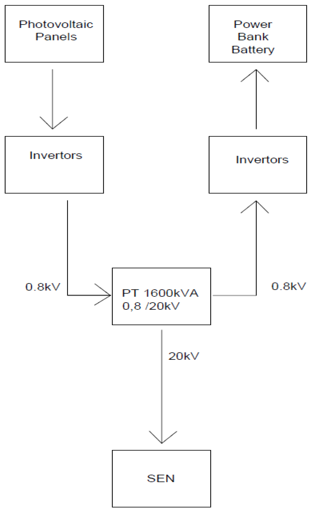
The inverters enable connection to the national grid through a 0.8/20 kV transformer and an electricity meter, ensuring efficient energy transmission. The entire photovoltaic system is supported by a robust stainless-steel structure, strategically oriented southward and tilted at an angle of 35 degrees to optimize the annual energy yield. This specific tilt is crucial for maximizing the park’s energy production throughout the year. Visual representations of the farm are available, with Figure 1 depicting the layout of the photovoltaic farm and Figure 2 providing a schematic block diagram of the system’s electrical connection.
The park’s design includes several advanced features to enhance its performance and reliability. The stainless-steel structure not only ensures durability but also supports the optimal orientation and tilt of the panels, which is essential for capturing maximum solar energy. The connection to the national grid via the transformer and electricity meter is designed to facilitate smooth and efficient energy transport, minimizing losses and ensuring a stable supply of electricity. By incorporating these elements, the photovoltaic park in Tulcea County stands as a model of efficient and sustainable energy production [6].
To illustrate the concept depicted in Figure 1 regarding the arrangement of photovoltaic panels on a metal support structure in multiple parallel rows, consider the following configuration:
Visualize a robust metal structure, likely made of aluminum or steel, engineered to maximize sun exposure. This framework supports several photovoltaic (solar) panels arranged systematically in parallel rows. Each row consists of panels mounted side by side, all oriented in the same direction to optimally capture sunlight throughout the day. The alignment and spacing of each panel are crucial for efficiency, ensuring that there is no shading between panels and that each panel operates at its full capacity. This precise arrangement is essential for maintaining optimal energy production and enhancing the overall efficiency of the photovoltaic system [7].
This type of configuration is commonly found in solar farms or large-scale solar installations where the goal is to generate electricity sustainably. The metal support structure not only secures the panels firmly but is also designed to withstand various environmental conditions such as wind, rain, and temperature fluctuations [8]
By optimizing the surface area exposed to sunlight, this setup ensures that the maximum amount of solar energy is converted into electrical energy, thereby enhancing the efficiency of the power generation system. This design effectively combines the strength and durability of metal structures with the renewable energy potential of photovoltaic panels, resulting in a robust and efficient energy production solution. The careful engineering of the metal supports ensures longevity and reliability, making it a practical choice for large-scale solar energy projects [9].
Figure 2 presents an advanced block diagram of a solar-powered park system, detailing the energy flow from its generation by photovoltaic panels to its final usage and distribution. The overall operation can be divided into several key stages:
1. Energy Generation: The primary energy generation in this park system begins with photovoltaic panels, which are strategically positioned to capture sunlight. These panels are composed of solar cells, typically made from silicon, which convert sunlight directly into electricity through the photovoltaic effect. The effectiveness of this stage depends on several factors, including the panel’s efficiency, orientation, and the amount of sunlight the park receives [7].
2. Energy Storage: Once the electricity is generated, it needs to be stored for consistent supply, especially during periods when sunlight is not available (e.g., nighttime, cloudy or rainy days). This is where batteries come into play. In the park’s system, large-scale battery storage units are used to store the electricity produced by the solar panels. These batteries are designed to handle high capacities and are capable of storing energy for extended periods, thereby stabilizing the supply and ensuring that the park has a continuous energy resource [10].
3. Energy Management and Distribution: The energy management system (EMS) is critical in this setup. It monitors and controls the flow of electricity, ensuring that the energy produced is either directed to the batteries for storage or to meet immediate power demands within the park. When the batteries are fully charged and the park’s energy requirements are met, the EMS redirects the surplus energy [11].
4. Injection into the Power Grid: The excess energy, which is not required by the park or exceeds the storage capacity of the batteries, is injected into the local power grid. The AC electricity is then compatible with the grid and can be distributed to power homes, businesses, and other facilities outside the park. This not only helps in reducing the park’s carbon footprint but also supports the local community by providing green energy, which can decrease reliance on fossil fuels [12].
5. Sustainability and Efficiency: The described park system highlights a self-sustaining, efficient, and environmentally friendly approach to energy management. By using renewable energy sources like solar power, the park minimizes its environmental impact while ensuring operational efficiencies. Additionally, the use of advanced battery storage technologies and an intelligent EMS allows for optimized energy distribution, reducing waste and increasing the overall reliability of the system [4,13].
This park system is an excellent example of how modern technology can be leveraged to create eco-friendly, sustainable solutions that benefit both the environment and the community. By integrating solar power generation with sophisticated energy storage and management systems, parks like these can serve as models for renewable energy utilization in urban planning and infrastructure development [14].

3. System Analysis

3.1. The Technical Characteristics of the Photovoltaic Panels

The planned development of the CEF Galati photovoltaic park represents a significant advancement in renewable energy infrastructure within the region. This project entails the installation of a large-scale photovoltaic plant equipped with high-efficiency components designed to maximize energy output and ensure sustainable operations. Here, we delve into the technical characteristics and implications of this initiative:
Photovoltaic Modules: The heart of the CEF Tulcea photovoltaic park consists of 5,490 photovoltaic modules, each boasting a capacity of 504 watts peak (Wp). These modules play a pivotal role in converting sunlight into electrical energy. The selection of high-wattage modules is key to enhancing the efficiency and overall output of the photovoltaic plant, resulting in a total installed power capacity of 2,800 kWp from the panels alone. This configuration underscores the park’s dedication to utilizing advanced technology for efficient energy generation [15].
The use of these high-capacity modules not only boosts the park’s energy production but also optimizes space utilization, allowing for more energy to be generated within a given area. Furthermore, the integration of such sophisticated components highlights the project’s commitment to cutting-edge renewable energy solutions, positioning the CEF Tulcea photovoltaic park as a leader in sustainable energy initiatives [5,16].
Inverter configuration: Complementing the solar modules are 8 inverters, each rated at 330 kW. Inverters play a vital role in the PV system, converting the direct current (DC) output from solar panels into alternating current (AC), which is suitable for use in power grids and by end consumers. The total capacity of the inverter reaches 2,640 kW, which exceeds the capacity of the panel, ensuring that the inverters can efficiently handle the maximum power generated by the panels at all times [17].
Calculation of installed power: The installed power in the case of CEF Tulcea is identified as 2,800kW, based on the smaller capacities of the two panels and inverters. This conservative approach is usually adopted in PV installations to ensure system efficiency and safety. It prevents the scenario where the energy produced by the solar panels exceeds the conversion capacity of the inverters, which could lead to potential energy losses or system failures [18].
System Design and Efficiency: The design of the photovoltaic park is aimed at maximizing energy harvest while ensuring reliability and durability. The layout of the panels, their angle, and orientation are calculated to capture the maximum amount of solar radiation throughout the year. System efficiency is also enhanced by the strategic placement of inverters and the use of high-quality cabling to minimize transmission losses.
Sustainability and Environmental Impact: The implementation of the CEF Tulcea photovoltaic park represents a forward-thinking approach to energy generation, focusing on sustainability. By deploying a significant capacity of solar energy, the park will significantly reduce carbon emissions compared to conventional fossil fuel-based power plants. This shift not only helps in mitigating climate change but also promotes local environmental sustainability [19].
Economic and Community Benefits: Beyond environmental benefits, the photovoltaic park is expected to contribute economically to the region. It will provide local jobs during the construction and maintenance phases and generate clean energy that could potentially reduce electricity costs for local businesses and households. Moreover, such projects often encourage technological and infrastructure development in the area, fostering a more robust local economy [20].
Table 1 represents the mechanical specifications of the photovoltaic panels used. You can see the dimensions of the panel used, the weight and the section of the cables.
Table 2 represents the electrical specifications of the photovoltaic panels used. It can be seen that this type of panels has an efficiency of approximately 21.57%.
In Table 3 you can see the operational parameters of the photovoltaic panels.
The photovoltaic panels selected for the project are high-quality units manufactured by SERAPHIM. The specific model chosen is part of the “SV-Series” range, identified as “SRP-670-BMC-BG”. These panels have been thoroughly analyzed and selected for their superior performance and reliability [21].

3.2. The Technical Characteristics of the Invertors

The SUN2000-330KTL-H1 is a sophisticated inverter model developed by Huawei, specifically engineered for large-scale commercial and utility applications. It is designed to deliver high efficiency, exceptional reliability, and intelligent management capabilities. As a member of Huawei’s renowned SUN2000 series, this inverter is celebrated for its robust performance across diverse environmental conditions and its incorporation of advanced technologies. This ensures optimal energy conversion and seamless integration into modern photovoltaic systems, making it an ideal choice for maximizing the efficiency and reliability of large-scale solar power installations [9,22].
Technical Specifications and Features:
Rated Power: The SUN2000-330KTL-H1 inverter boasts a maximum AC output power of 330 kW, making it ideally suited for large-scale photovoltaic systems. Its high capacity enables it to efficiently handle extensive solar arrays, converting the DC output from the panels into high-quality AC power for seamless grid integration [23].
Efficiency: A key highlight of this inverter is its exceptional conversion efficiency, with a peak efficiency of up to 98.65%. This high level of efficiency ensures that minimal solar energy is lost during the DC to AC conversion process, which is critical for maximizing the return on investment in solar energy projects. This efficiency contributes significantly to the overall performance and financial viability of solar installations [24].
MPPT (Maximum Power Point Tracking): It is equipped with advanced MPPT algorithms capable of rapid tracking and adapting to various sunlight conditions. This technology helps maximize the energy harvest from the photovoltaic panels, especially under varying weather conditions. The inverter supports multiple MPPT inputs, allowing for versatile configurations of the solar array and optimizing performance across different panel groups [25].
Smart Cooling Design: The SUN2000-330KTL-H1 employs an intelligent cooling system that adjusts fan speed based on internal temperature and external environmental conditions. This feature not only prolongs the life of the inverter by reducing thermal stress but also minimizes operational noise, making it ideal for installations close to residential areas [26].
Communication and Connectivity: Huawei has equipped the SUN2000-330KTL-H1 with multiple communication options, including Ethernet and RS485 interfaces. These features facilitate remote monitoring and management of the inverter, which is essential for maintaining optimal operation throughout the life of the photovoltaic system. The inverter can be integrated into Huawei’s smart photovoltaic management system, allowing for real-time data analysis and performance optimization [27].
Safety Features: Safety is a paramount concern for any electrical system, and the SUN2000-330KTL-H1 includes several integrated safety mechanisms. It features built-in surge protection and residual current detection, reducing the risk of fire and ensuring the safety of the photovoltaic system and its operators. Furthermore, the inverter is designed to comply with international safety standards for solar energy systems [28].
Durability and Reliability: The inverter is built to withstand harsh environmental conditions, featuring a high degree of protection against dust and water ingress. Its robust design ensures reliable operation over a wide range of temperatures and weather conditions, making it suitable for deployment in various geographical locations [29].
Applications and Usability:
The SUN2000-330KTL-H1 is designed primarily for large commercial installations or utility-scale solar farms. Its high-power output and efficiency make it an excellent choice for projects aiming to reduce carbon footprints and achieve energy independence. Additionally, its smart management features and compatibility with modern monitoring systems make it easy to integrate into existing power infrastructure, allowing for scalable and flexible solar energy solutions [30].
In summary, the Huawei SUN2000-330KTL-H1 inverter stands out in the market for its efficiency, reliability, and smart features, making it a top choice for stakeholders in large-scale solar energy projects looking for a dependable and high-performing inverter solution [9,31].
Table 5 shows the technical values from the technical sheet of the inverter used in this work.

3.3. The Technical Characteristics of the Transformation Substation in the Concrete Tire

For effective management and distribution of electricity produced by solar parks or other renewable energy sources, integrating a medium voltage transformer station is crucial. This facility plays a vital role, particularly in stepping up the voltage for efficient transmission and ensuring compatibility with the national energy system [32].
Purpose and Functionality:
A medium voltage transformer substation typically includes a key component known as a step-up power transformer. In the context of a solar park or similar setup, this transformer might be rated at 0.8/20kV. This specification indicates that the transformer can increase the voltage from 0.8 kV (800 volts), which is often the output level from local distribution panels, to 20 kV (20,000 volts). This higher voltage is necessary for transmission over long distances with minimal loss of energy [33].
Key Features of a 0.8/20kV Step-Up Power Transformer:
Voltage Transformation: The primary function of the 0.8/20kV transformer is to elevate the voltage from a lower level produced by the energy generating source (e.g., solar panels) to a medium voltage level suitable for grid integration. This transformation reduces current while maintaining the same power level, which decreases energy losses during transmission through power lines [34].
Energy Efficiency: Transformers designed for such applications are highly efficient, typically operating with high energy efficiency ratings to minimize power losses. This efficiency is crucial in maximizing the net energy output of renewable energy projects [35].
Grid Compatibility: By stepping up the voltage to 20kV, the transformer aligns the produced electricity with the voltage levels required by the national grid. This compatibility is essential for the seamless injection of electricity into the grid, ensuring that the energy can be distributed and used in residential, commercial, and industrial sectors [36].
Safety and Reliability: Medium voltage transformers are equipped with various safety features to handle faults and fluctuations in input power. They are built to withstand environmental stresses and operate reliably over long periods, which is critical in infrastructure that supports essential services like electricity [37].
Regulatory Compliance: Such transformers are designed to meet local and international standards for safety, performance, and environmental impact. This compliance is vital for ensuring that the transformer station can legally and safely operate within the energy network [38].
Applications in Energy Projects:
In renewable energy installations such as solar parks, the medium voltage transformer station not only serves as a hub for voltage transformation but also acts as a monitoring and control center. It often includes switchgear, protection devices, and metering equipment, which collectively help manage the flow of electricity, protect against overloads, and accurately record energy production for billing and analysis [39].
Integrating a 0.8/20kV transformer substation into a solar park or similar project ensures that the electricity generated is effectively adapted and safely transmitted to the grid, enhancing the overall efficiency and viability of renewable energy projects. This setup is crucial for expanding the reach and impact of green energy initiatives, contributing significantly to energy sustainability goals [40,41,42,43].
The transformation substation is composed of [40,41,43,44]:
- Medium voltage line cell with motorized load separator and motorized fixed switch and protection relay, equipped with three current transformers and three voltage transformers;
- Measuring cell without switching equipment, equipped with three current transformers, three voltage transformers and power quality analyzer;
- Medium voltage transformer cell with motorized load separator and motorized fixed switch and protection relay, equipped with three current transformers and three voltage transformers;
- The medium voltage cable on the connection between the transformer cell and the power transformer;
- Transformers 1600kVA, 0.8/20kV, oil, Tier2
- The low-voltage cable for the connection between the transformer and the general low-voltage distribution board;
- The general low-voltage distribution board equipped with a 3P 1600A motorized general switch, 3P 32A fixed switch, for the distribution board power supply, 11 vertical separators NH2 pole-to-pole operation, 33 fuses MPR 250A Gr 2.;
- The connection cable between the general low-voltage distribution board and the transformer 2;
- Transformer 2 0.8/0.4kV 40kVA, cast resin;
- The connection cable between transformer 2 and the distribution board;
- Distribution board equipped with 3P 160A manual main switch and 4 outlets with NH00 vertical three-pole separators with 12 MPR 25A Gr.00 fuses;
- The substation’s internal services panel with rectifier and batteries.
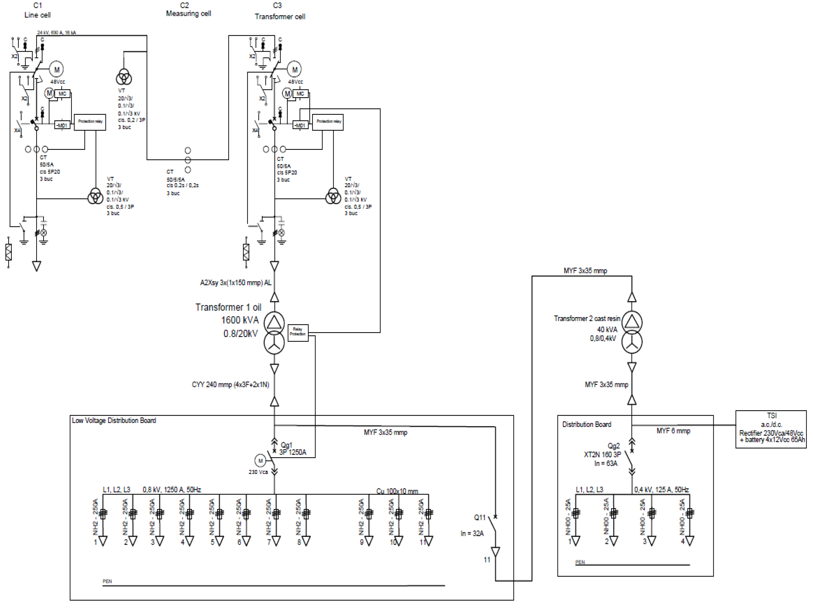
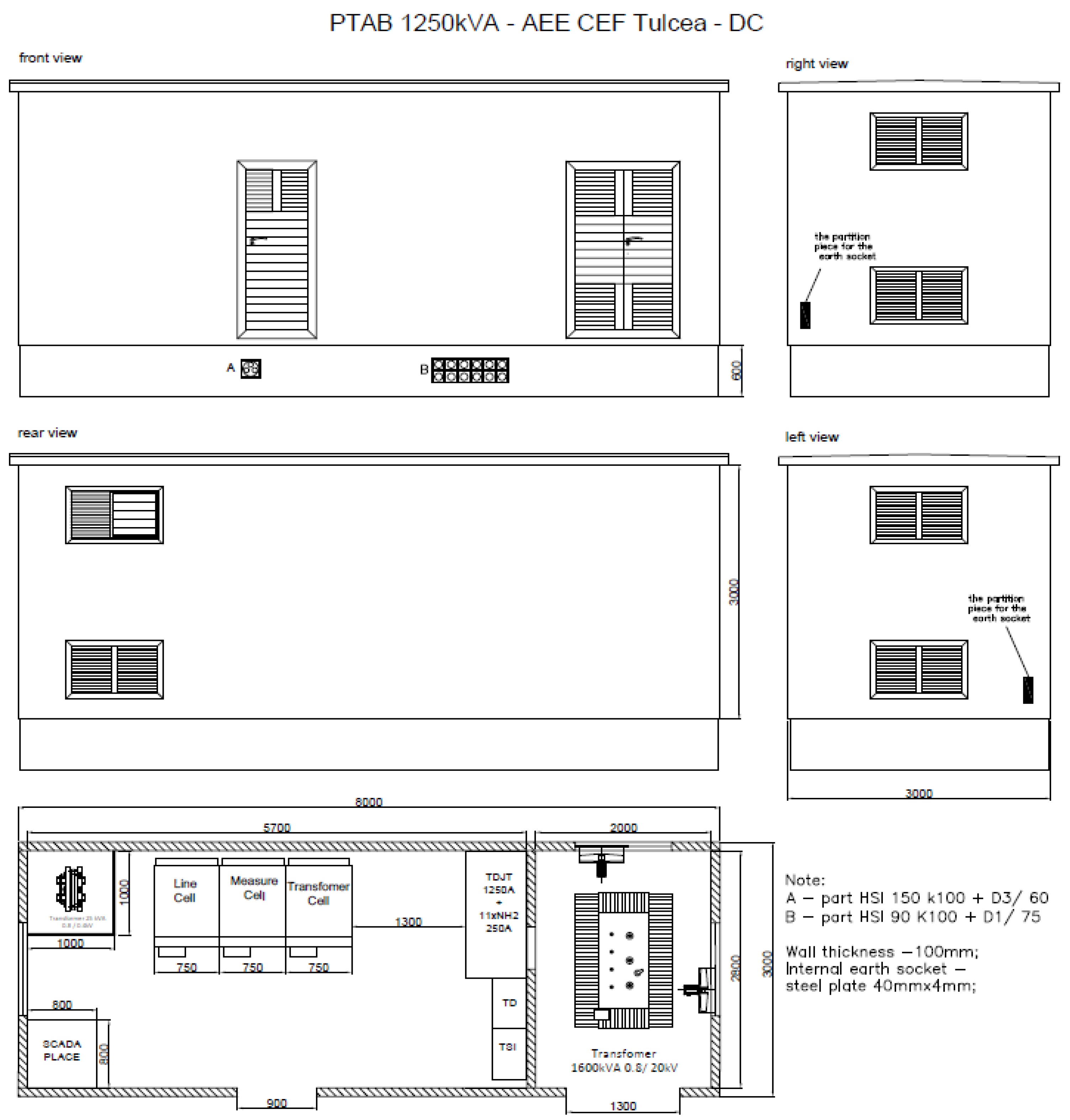
Figure 3 and Figure 4 provide detailed insights into the design and structural arrangement of a medium voltage transformer substation, each focusing on different aspects of the facility.
Figure 3: Single-Wire Scheme of the Transformer Station
Figure 3 is a schematic diagram, detailing the single-wire electrical connections within the transformer station. This type of diagram is crucial for understanding the electrical flow and component layout, offering a clear view of how the transformer and associated equipment are interconnected. The schematic would typically include:
Step-Up Transformer: Central to the diagram, this transformer’s role is to step up the voltage from 0.8 kV to 20 kV. It would be depicted as the core component through which all generated electricity must pass.
Switchgear: Essential for protection and control, switchgear is represented in the scheme, showing how it is linked to both the input from the renewable energy source and the output to the grid. It helps in managing the load, protecting the system from overloads, and isolating parts of the network for maintenance.
Protection Devices: These are crucial for safeguarding the transformer station from electrical faults. They would include circuit breakers and relays, strategically placed to quickly disconnect damaged sections of the network to prevent further system harm.
Metering Equipment: This would be shown to indicate how energy production and flow are measured. This equipment is vital for operational management, billing, and analyzing the efficiency of energy transmission.
Figure 4: Constructive Arrangement of the Transformer Station
In contrast, Figure 4 would provide a visual representation of the physical layout of the transformer station. This constructive drawing or image showcases the actual building and positioning of equipment within a real-world setting, including:
Building Layout: This would depict the size, shape, and structure of the building housing the transformer and other critical components. It gives an idea of the physical space required for such an installation and how components are arranged for optimal functionality.
Equipment Positioning: Detailed placements of the transformer, switchgear, protection devices, and metering systems within the building would be shown. This arrangement ensures that operational efficiency is maintained, and there is easy access for maintenance and monitoring.
Safety and Accessibility Features: Safety measures like fire suppression systems, emergency exits, and ventilation systems would be illustrated, along with pathways for personnel to move within the station safely.
Environmental Controls: Since transformers can generate significant heat, cooling systems or natural ventilation methods would also be depicted to maintain an optimal operating temperature within the facility [40].
Integration into the Overall System:
Together, Figure 3 and Figure 4 provide comprehensive documentation necessary for the construction, operation, and maintenance of a medium voltage transformer substation. They ensure that engineers and technicians have precise guidelines for electrical wiring and physical setup, leading to a safer, more efficient operation. This detailed documentation is indispensable for planning, execution, regulatory compliance, and future reference throughout the lifetime of the substation.

4. Photovoltaic Park Simulation

4.1. Description of the Simulation

Simulating the photovoltaic park using the ETAP application is a crucial step in the design and validation process of the solar power system. ETAP, or Electrical Transient Analyzer Program, is a comprehensive engineering software suite offering a range of integrated electrical engineering applications. It is extensively utilized for the simulation, design, analysis, optimization, monitoring, control, and automation of electrical power systems [8].
Application of ETAP in Photovoltaic Park Simulation:
System Design and Modeling: ETAP enables engineers to construct a detailed digital model of the photovoltaic park. This model incorporates all essential components, including solar panels, inverters, transformers, protection devices, and the grid connection. With its advanced modeling capabilities, ETAP accurately represents the physical and electrical characteristics of each component. This precise digital replication allows for thorough analysis and optimization, ensuring the photovoltaic system operates efficiently and reliably.
Performance Analysis: Using ETAP, engineers can simulate the performance of the photovoltaic park under various conditions. This includes analyzing the impact of sunlight variability, temperature changes, and equipment efficiency on the overall energy output. The software can perform both steady-state and dynamic analyses, providing insights into how the system behaves over different times of the day and under different weather conditions.
Load Flow Analysis: ETAP’s load flow analysis feature helps in determining the voltage drops, power losses, and load distribution within the electrical system of the photovoltaic park. This analysis is essential for ensuring that the system is optimized for maximum efficiency and reliability.
Fault Analysis: The application can simulate different types of faults (such as short circuits) within the system to evaluate the response of protective devices and the robustness of the system architecture. This analysis is crucial for ensuring the safety and durability of the park, minimizing the risk of damage or downtime.
Reliability Assessment: ETAP also includes tools for assessing the reliability of the power system, which is vital for planning maintenance schedules and improving system designs to avoid failures and ensure continuous power production.
Grid Integration: One of the most significant aspects of ETAP simulations is analyzing how the photovoltaic park interacts with the electrical grid. This includes assessing the impact of power injection from the park into the grid and ensuring compliance with grid codes and standards.
Optimization and Scalability: The software allows for the optimization of the electrical system design, helping to reduce costs and improve performance before physical implementation. It also supports scalability, enabling engineers to simulate expansions or modifications to the photovoltaic park as demands grow or technology evolves.
Benefits of Using ETAP:
Using ETAP for the simulation of a photovoltaic park offers several benefits:
Accuracy: Provides high-accuracy simulations that can predict real-world behaviors of electrical systems.
Efficiency: Enhances the efficiency of the design and helps in identifying potential issues before they occur in the real world.
Cost-effectiveness: Reduces the overall cost by optimizing the system design and minimizing the risk of expensive failures.
Compliance and Safety: Ensures that the system meets all relevant standards and regulations, enhancing safety and compliance.
In summary, the simulation of the photovoltaic park in ETAP is a pivotal element in the project lifecycle, offering a robust platform for designing, analyzing, and optimizing the electrical systems of renewable energy projects. This helps ensure that the park will operate efficiently, safely, and in harmony with the electrical grid [8].

4.2. Simulation in ETAP

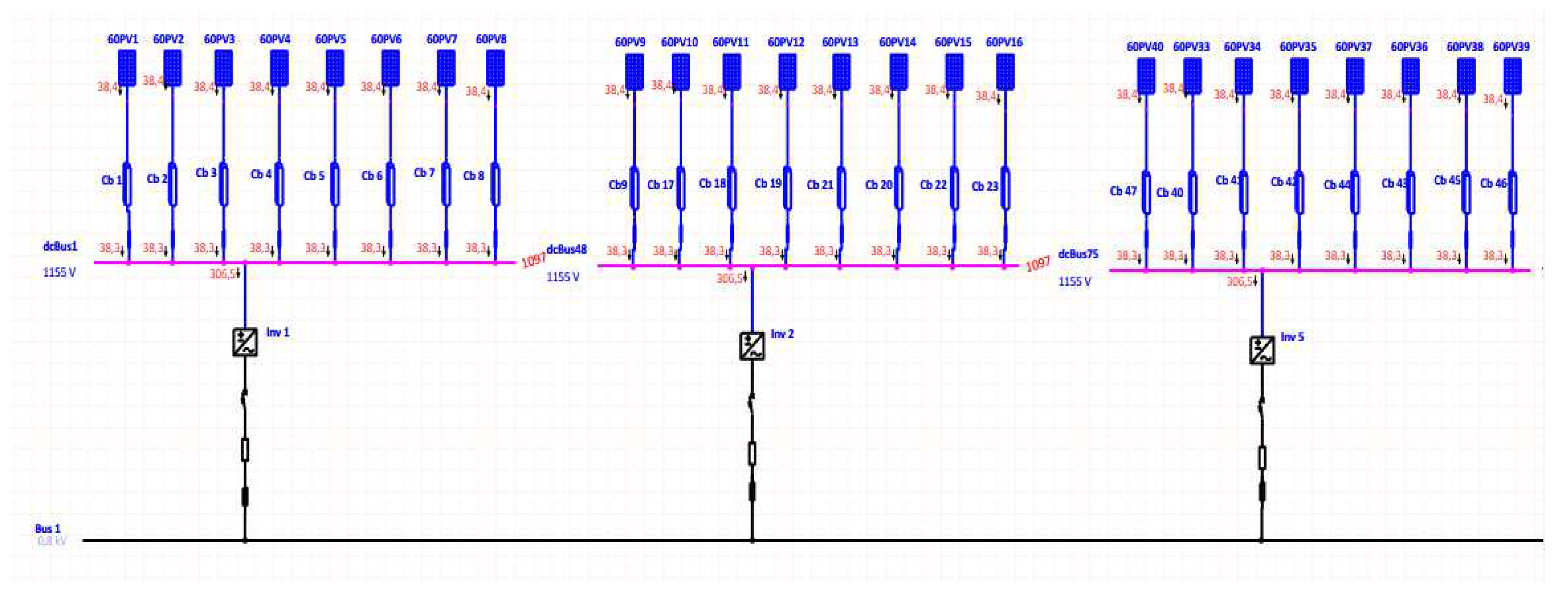
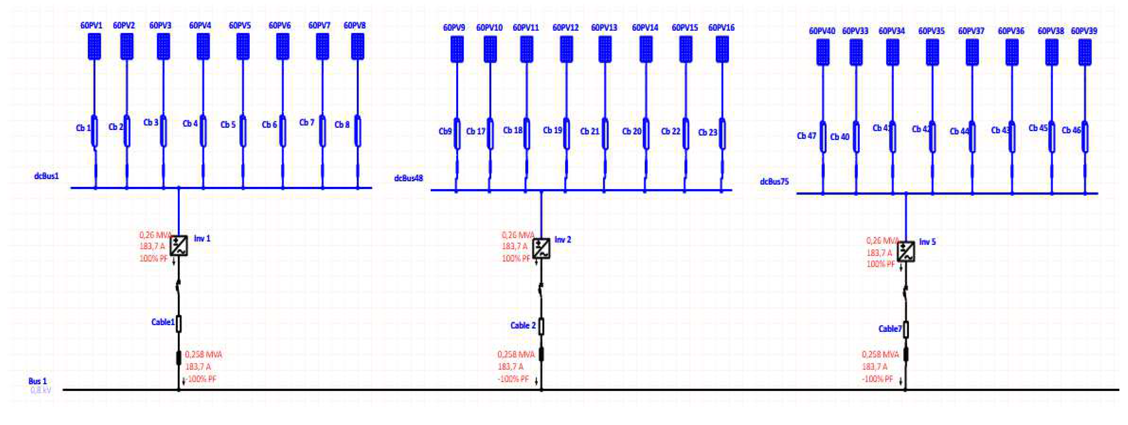
In Figure 5, the connection between the photovoltaic installation and the transformer substation plays a crucial role in the efficiency and stability of the entire energy system. This connection is responsible for transporting the direct current (DC) generated by the photovoltaic panels to the transformer station, where it will be converted into alternating current (AC) to be integrated into the electrical grid.
In Figure 6, the values of currents and power in alternating current are shown.
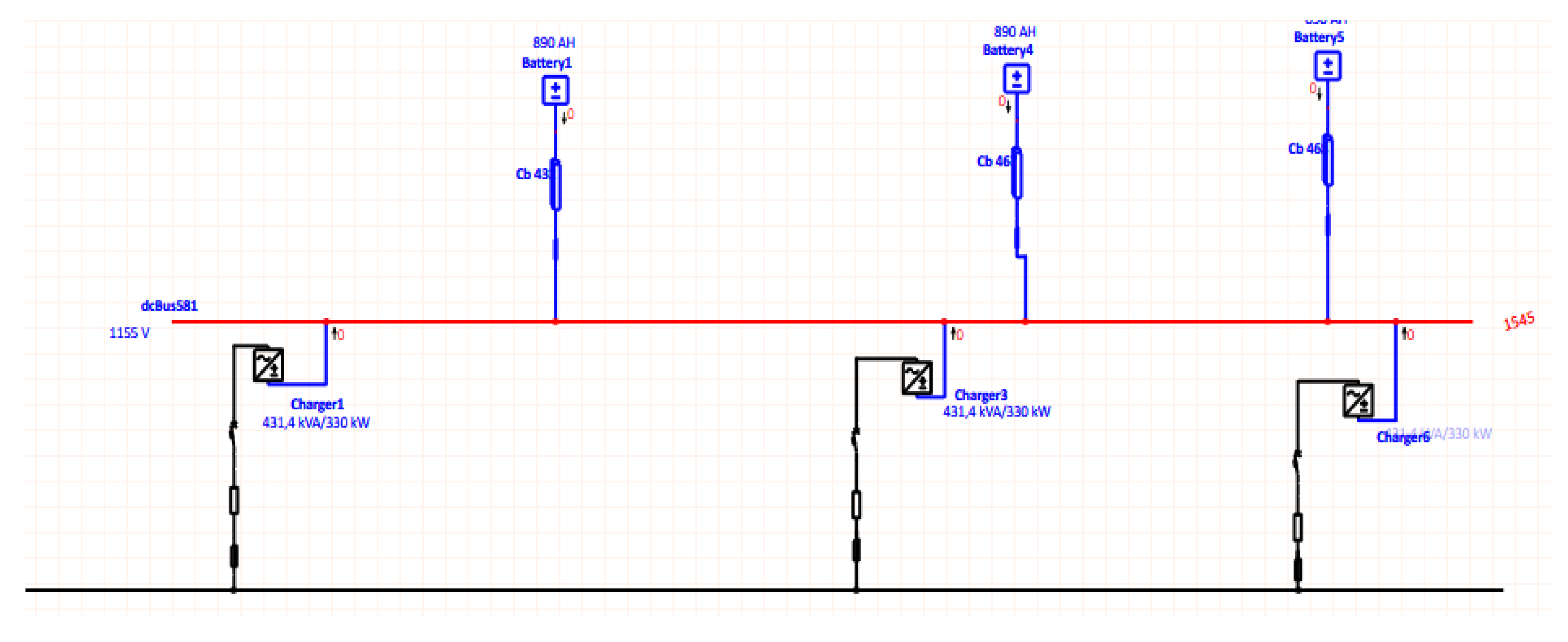
In the context of modern energy systems, the integration of storage batteries in photovoltaic networks is essential to ensure the stability and continuity of the energy supply. The connection between the substation and the DC storage battery involves several technical and design aspects aimed at optimizing system performance and efficiency.
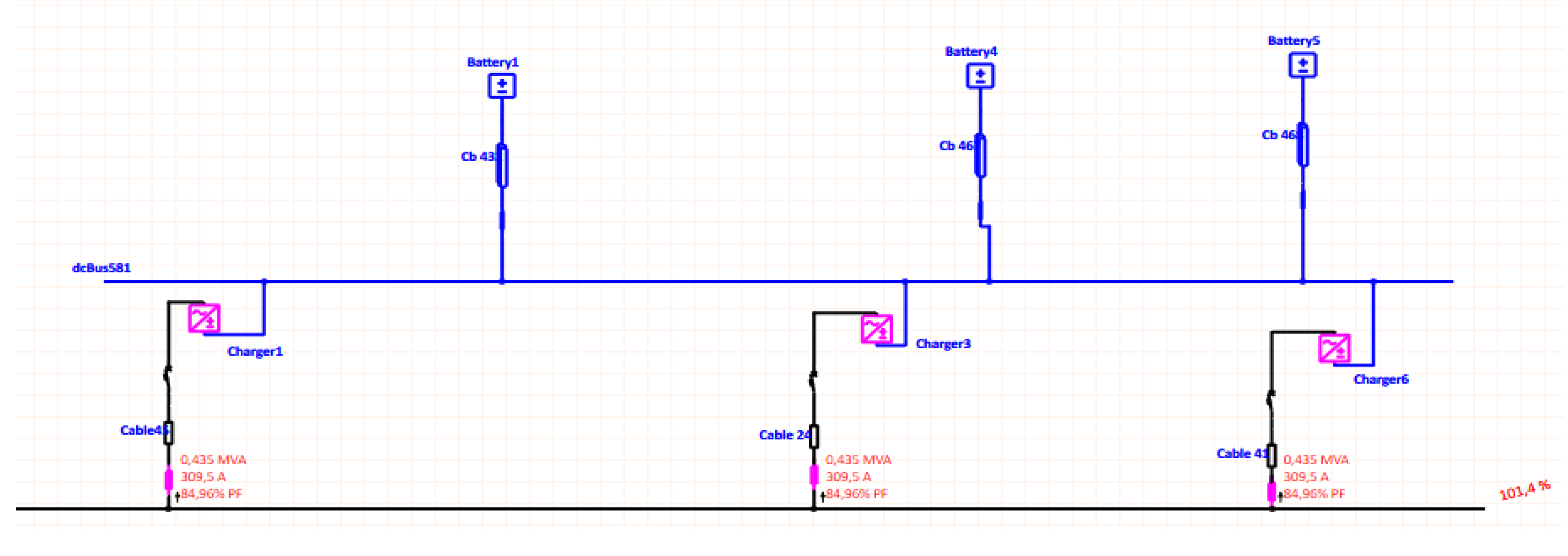
Figure 8 shows the connection between the transformer substation and the storage battery rendered in alternating current.
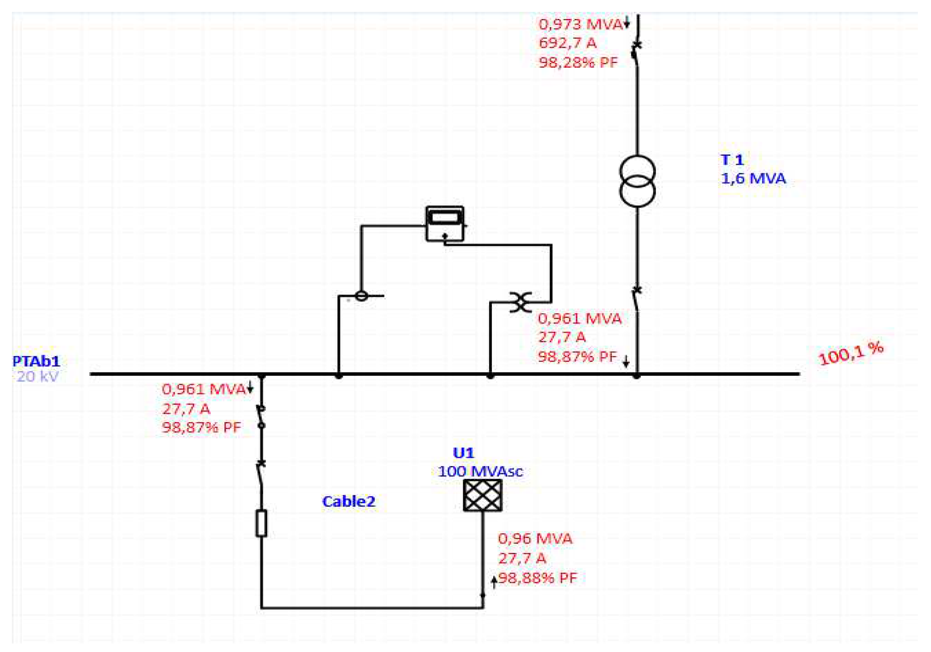
The 0.8/20kV substation plays an important role in this system, especially in connection with photovoltaic plants and other renewable energy sources. This substation is responsible for transforming the voltage from a lower level (0.8kV) to a higher level (20kV), suitable for distribution and integration into the electrical network.

4.3. Economic Calculation

Simulating the photovoltaic park using the ETAP application is a crucial step in the design and validation process of the solar power system. ETAP, or Electrical Transient Analyzer Program, is a comprehensive engineering software suite offering a range of integrated electrical engineering applications. It is extensively utilized for the simulation, design, analysis, optimization, monitoring, control, and automation of electrical power systems.
Table 6 shows the financial part of the entire work. In this calculation, both the economic values for the purchase of the equipment and the completion of the work, as well as the calculations for the amortization of the investment over time, are included.

5. Conclusion

This project emphasizes the deployment of high-performance photovoltaic modules, specifically the 504 Wp models, alongside the advanced SUN2000-330KTL-H1 inverters, showcasing a strong commitment to leveraging state-of-the-art technology. This approach ensures optimal operation of the solar farm, enabling it to generate substantial energy even under fluctuating environmental conditions.
A crucial element of the installation is the medium voltage substation, which in-cludes a 0.8/20kV step-up transformer. This substation is vital for increasing the voltage generated by the solar park to levels suitable for efficient transmission and integration into the national grid. This highlights the importance of robust infrastructure in enabling the seamless transition from renewable energy generation to widespread utilization [24].
Sophisticated software, such as ETAP, is invaluable for simulation and optimization purposes. ETAP’s capabilities in modeling, analyzing, and optimizing electrical systems ensure that the photovoltaic farm operates at maximum efficiency, with minimal losses and enhanced safety. This comprehensive approach not only enables accurate perfor-mance predictions under varying conditions but also supports informed decision-making regarding potential system expansion and integration [24]..
The design and operational strategies of this project are deeply rooted in sustainabil-ity. By converting sunlight into clean electricity and feeding it into the national grid, the photovoltaic park significantly contributes to reducing carbon emissions and decreasing dependence on fossil fuels. This strategy aligns with global environmental objectives and benefits local communities by providing a reliable, sustainable energy source.
In addition to environmental benefits, the photovoltaic park offers significant eco-nomic advantages. It creates job opportunities during both the construction and opera-tional phases and stimulates local economies through improved energy infrastructure. Furthermore, by producing clean energy, the park contributes to stabilizing local energy prices and reducing overall energy costs, thereby fostering economic stability and growth [33].
The design and implementation of the photovoltaic park have been carried out with scalability in mind. This strategic foresight ensures that the park can easily accommodate future expansions or technological upgrades as innovations emerge and energy demand increases [45].
In conclusion, the establishment of this photovoltaic park represents a forward-thinking initiative that effectively leverages advanced technology and strategic planning to maximize energy production. It serves as a model for future renewable energy projects, aiming for high efficiency, sustainability, and seamless integration into existing energy infrastructures. This project not only addresses current energy needs but also prepares for future growth and technological advancements, embodying a holistic approach to renewable energy development [34].

Author Contributions

All authors contributed equally to the creation of the article. All authors have read and agreed to the published version of the manuscript.

Data Availability Statement

The raw data supporting the conclusions of this article will be made available by the authors on request.

6. Acknowledgment

This work was supported by a grant from the Ministry of Research, Innovation, and Digitization, CNCS-UEFISCDI, project number PN-III-P4-PCE-2021-0777, within PNCDI III, contract PCE 5/2022 and by a grant of the Ministry of Research, Innovation and Digitalization, project number PNRR-C9-I8-760111/23.05.2023, code CF 48/14.11.2022”.

Conflicts of Interest

The authors declare no conflict of interest.

References

  1. Kymakis, E.; Kalykakis, S.; Papazoglou, T.M. Performance analysis of a grid connected photovoltaic park on the island of Crete. Energy Convers. Manag. 2009, 50, 433–438. [Google Scholar] [CrossRef]
  2. J. Syllignakis and T. M. Papazoglou, “Study of Impact on Crete system operation of the Atherinolakos power plant,” in Proceedings of the 41st international universities power engineering conference, IEEE, 2006, pp. 482–485.
  3. Jafari, H.; Habibi, M. High-Voltage Charging Power Supply Based on an LCC-Type Resonant Converter Operating at Continuous Conduction Mode. IEEE Trans. Power Electron. 2019, 35, 5461–5478. [Google Scholar] [CrossRef]
  4. Lazaroiu, A.C.; Osman, M.G.; Strejoiu, C.-V.; Lazaroiu, G. A Comprehensive Overview of Photovoltaic Technologies and Their Efficiency for Climate Neutrality. Sustainability 2023, 15, 16297. [Google Scholar] [CrossRef]
  5. Yoo, C.-B. Park, and J. Lee, “A study on design of photovoltaic system using electrical railway stations,” in 2016 19th International Conference on Electrical Machines and Systems (ICEMS), IEEE, 2016, pp. 1–5.
  6. M. E. Vanggaard and D. T. Lund, “Design of a standalone PV system for Greenland, Dep. of Civil Engineering, Danmarks Tekn,” Univ.(DTU), 2009.
  7. N. D. Hatziargyriou, A. Tsikalakis, and A. Androutsos, “Status of distributed generation in the Greek islands,” in 2006 IEEE Power Engineering Society General Meeting, IEEE, 2006, pp. 6-pp.
  8. Inginerie mecanică și a instalațiilor.” Accessed: Jul. 08, 2024. [Online]. Available: https://www.eplan.
  9. “O gamă de produse care oferă soluții solare fiabile | FusionSolar România.” Accessed: Jul. 08, 2024. [Online]. Available: https://solar.huawei.
  10. Lazaroiu, G.; Osman, M.G.; Strejoiu, C.-V. Performance Evaluation of Renewable Energy Systems: Photovoltaic, Wind Turbine, Battery Bank, and Hydrogen Storage. Batteries 2023, 9, 468. [Google Scholar] [CrossRef]
  11. Lakervi, E.; Holmes, E.J. Electricity Distribution Network Design; Institution of Engineering and Technology (IET): Stevenage, Hertfordshire, United Kingdom, 2003. [Google Scholar]
  12. Osman, M.G.; Strejoiu, C.-V.; Panait, C.; Lazaroiu, A.C.; Lazaroiu, G. Microgrid Model for Evaluating the Operational Dynamics of Solar-Powered Hydrogen Production. 2024 9th International Conference on Energy Efficiency and Agricultural Engineering (EE&AE), Bulgaria.
  13. Wang, C.; He, S.; Liu, L.; Li, X.; Gao, L. Tradeoff between the efficiency penalty and load depth in a coal-fired power plant with CO2 capture under partial load conditions. Energy Convers. Manag. 2023, 278. [Google Scholar] [CrossRef]
  14. Silva, M.; Castro, R.; Batalha, M. Technical and Economic Optimal Solutions for Utility-Scale Solar Photovoltaic Parks. Electronics 2020, 9, 400. [Google Scholar] [CrossRef]
  15. M. Radic and D. Jovanovic, “Methodology for determination of 110/35 kV and 110/20 kV substation revitalization order,” in CIRED 2009-20th International Conference and Exhibition on Electricity Distribution-Part 1, IET, 2009, pp. 1–5.
  16. Decker, B.; Jahn, U. Performance of 170 grid connected PV plants in Northern Germany—Analysis of yields and optimization potentials. Sol. Energy 1997, 59, 127–133. [Google Scholar] [CrossRef]
  17. M. T. Hagh, “DESIGN AND INSTALLATION OF FIRST 20 kV SPACER CABLE IN IRAN,” in 21st International Conference on Electricity Distribution, CIRED, 2011, pp. 6–9.
  18. Crowe, R. The Treaty of Lisbon: A Revised Legal Framework for the Organisation and Functioning of the European Union. ERA Forum 2008, 9, 163–208. [Google Scholar] [CrossRef]
  19. P. E. Mark Rossow, “Grid Energy Storage”.
  20. S. Ziuku and E. L. Meyer, “Economic viability of a residential building integrated photovoltaic generator in South Africa,” International Journal of Energy and Environment, vol. 3, no. 6, pp. 905–914, 2012.
  21. Solar Cell Supplier - China Seraphim Solar Panel.” Accessed: Jul. 08, 2024. [Online]. Available: https://www.seraphim-energy.
  22. M. Widatalla and H. Zinko, “Designing a Photovoltaic Solar Energy System for a Commercial Building. Case Study: Rosa Park Hotel in Khartoum-Sudan,” in World Renewable Energy Congress-Sweden, 2011.
  23. Omer, A.M. Compilation and evaluation of solar and wind energy resources in Sudan. Renew. Energy 1997, 12, 39–69. [Google Scholar] [CrossRef]
  24. Lazaroiu, A.C.; Osman, M.G.; Strejoiu, C.-V.; Lazaroiu, G. A Comprehensive Overview of Photovoltaic Technologies and Their Efficiency for Climate Neutrality. Sustainability 2023, 15, 16297. [Google Scholar] [CrossRef]
  25. Razazian, K.; Umari, M.; Kamalizad, A.; Loginov, V.; Navid, M. G3-PLC specification for powerline communication: Overview, system simulation and field trial results. IEEE ISPLC 2010 - International Symposium on Power Line Communications and its Applications, pp. 2010. [Google Scholar] [CrossRef]
  26. H. Müller and T. Connor, “New 20kV network concept for an existing distribution network,” in 2010 China International Conference on Electricity Distribution, CICED 2010, IEEE, 2010, pp. 1–7.
  27. Ciulica, D.; Rob, R. Internal services simulation control in 220/110kV power transformer station Mintia. IOP Conf. Series: Mater. Sci. Eng. 2018, 294, 012009. [Google Scholar] [CrossRef]
  28. Scognamiglio, A. ‘Photovoltaic landscapes’: Design and assessment. A critical review for a new transdisciplinary design vision. Renew. Sustain. Energy Rev. 2015, 55, 629–661. [Google Scholar] [CrossRef]
  29. Botsaris, P.N. An approach of the spatial planning of a photovoltaic park using the Constructal Theory. Sustain. Energy Technol. Assessments 2015, 11, 11–16. [Google Scholar] [CrossRef]
  30. Z. Wu, “Study on selection of transformer capacity and conductor cross-section related to 20kV network in high voltage distribution network,” in 2010 China International Conference on Electricity Distribution, CICED 2010, IEEE, 2010, pp. 1–6.
  31. Medio, S. Photovoltaic Design Integration at Battery Park City, New York. Buildings 2013, 3, 341–356. [Google Scholar] [CrossRef]
  32. Roboam, X.; Sareni, B.; Andrade, A. More Electricity in the Air: Toward Optimized Electrical Networks Embedded in More-Electrical Aircraft. IEEE Ind. Electron. Mag. 2012, 6, 6–17. [Google Scholar] [CrossRef]
  33. Knight, U. The logical design of electrical networks using linear programming methods. Proc. IEE Part A: Power Eng. 1960, 107, 306–314. [Google Scholar] [CrossRef]
  34. Dorel, S.; Osman, M.G.; Strejoiu, C.-V.; Lazaroiu, G. Exploring Optimal Charging Strategies for Off-Grid Solar Photovoltaic Systems: A Comparative Study on Battery Storage Techniques. Batteries 2023, 9, 470. [Google Scholar] [CrossRef]
  35. Ogden, J.M. Cost and performance sensitivity studies for solar photovoltaic/electrolytic hydrogen systems. Sol. Cells 1991, 30, 515–523. [Google Scholar] [CrossRef]
  36. Sidrach-De-Cardona, M.; López, L.M. Performance analysis of a grid-connected photovoltaic system. Energy 1999, 24, 93–102. [Google Scholar] [CrossRef]
  37. E. D. Dunlop, “Lifetime performance of crystalline silicon PV modules,” in 3rd World Conference onPhotovoltaic Energy Conversion, 2003. Proceedings of, IEEE, 2003, pp. 2927–2930.
  38. B. Croxford and M. Rizig, “Is photovoltaic power a cost-effective energy solution for rural peoples in western Sudan?,” 2006.
  39. H. Ritchie, P. Rosado, and M. Roser, “Greenhouse gas emissions,” Our world in data, 2023.
  40. Acasa – Td Proelectric.” Accessed: Jul. 08, 2024. [Online]. Available: https://td-proelectric.
  41. Home - SEL, S.p.A. Experience and innovation at Your service.” Accessed: Jul. 08, 2024. [Online]. Available: https://www.sel-electric.
  42. Grupul ABB - Tehnologii digitale de vârf pentru industrie.” Accessed: Jul. 08, 2024. [Online]. Available: https://new.abb.
  43. AutoCAD Web App - Sign In | Online CAD Editor & Viewer | Autodesk.” Accessed: Jul. 08, 2024. [Online]. Available: https://web.autocad.
  44. System Modeling & Visualization.” Accessed: Jul. 08, 2024. [Online]. Available: https://etap.
  45. S. Enache, A. Campeanu, I. Vlad, and M. A. Enache, “Optimization of Design of Very High Power Transformers in Power System,” in 12th International Symposium on Advanced Topics in Electrical Engineering, ATEE 2021, IEEE, 2021, pp. 1–6. [CrossRef]
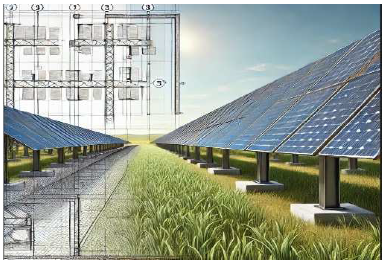
Figure 1. Photovoltaic panels mounted on the metal structure [6].
Preprints 116508 g001
Figure 2. Block diagram of the photovoltaic park.
Preprints 116508 g002
Figure 3. The single-wire diagram of the transformer substation.
Preprints 116508 g003
Figure 4. The constructive arrangement of the transformer station.
Preprints 116508 g004
Figure 5. ETAP - DC Load. The connection between the photovoltaic plant and the transformation substation.
Preprints 116508 g005
Figure 6. ETAP - AC Load. The connection between the photovoltaic plant and the transformation substation.
Preprints 116508 g006
Figure 7. ETAP - Storage DC. The connection between the transformation substation and storage battery.
Preprints 116508 g007
Figure 8. ETAP - Storage AC. The connection between the transformation substation and storage battery.
Preprints 116508 g008
Figure 9. ETAP - 0.8/20kV Transformer Substation.
Preprints 116508 g009
Table 1. Mechanical specifications [21].
Cell type P type Mono-crystalline
No. of cells 132
Dimensions 2384×1303×35mm
Weight 38.5 kg
Front Glass 2.0mm, AR coating semi-tempered glass, low iron
Frame Anodized Aluminium Alloy
Jonction Box IP68, 3 diodes
Output Cables 4.0mm2, 250mm(+)/350mm(-) or Customized Length
Table 2. Electric specification [21].
Module type SRP-670-BMC-BG
Testing condition STC NOCT
Maximum Power (Pmax) 670Wp 504Wp
Maximum Power Voltage (Vmp) 44.3V 41.38V
Maximum Power Current (Imp) 19.24A 15.55A
Open-circuit Voltage (Voc) 37.22V 34.15V
Short-circuit Current (Isc) 18.01A 14.76A
Module Efficiency STC (%) 21.57%
Standard Test Conditions (STC), Normal Operating Cell Temperature (NOCT).
Table 3. Operation parameters [21].
Operational temperature -40℃~+85℃
Maximum system voltage 1500VDC (IEC)
Maximum series fuse rating 30A
Power tolerance 0~+3%
Nominal operating cell temperature (NOCT) 45±2℃
Refer. Bifacial Factor 70±10%
Table 4. Temperature Rating (STC) [21].
Temperature coefficient of Isc 0.05%/℃
Temperature coefficient of Voc -0.26%/℃
Temperature coefficient of Pmax -0.34%/℃
Table 5. The technical sheet of the inverter.
Efficiency
Max. Efficiency ≥99.0%
European Efficiency ≥98.8%
Input
Max. Input Voltage 1,500 V
Number of MPP Trackers 6
Max. Current per MPPT 65 A
Max. Short Circuit Current per MPPT 115 A
Max. PV Inputs per MPPT 4/5/5/4/5/5
Start Voltage 550 V
MPPT Operating Voltage Range 500 V ~ 1,500 V
Nominal Input Voltage 1,080 V
Output
Nominal AC Active Power 300,000 W
Max. AC Apparent Power 330,000VA
Max. AC Active Power (cosφ=1) 330,000 W
Nominal Output Voltage 800 V,3W + PE
Rated AC Grid Frequency 50 Hz / 60 Hz
Nominal Output Current 216.6 A
Max. Output Current 238.2 A
Adjustable Power Factor Range 0.8 LG ... 0.8 LD
Total Harmonic Distortion <1%
Table 6. Economic calculation.
Performance of grid-connected PV:
Power for each panel: 504 W
Power for each invertor: 330 kW
The total power produced by the photovoltaic panels: 2640 kW
Yearly PV energy production: 3620 MWh
Total expenses:
Cost for PV: 2640000 €
Cost for Battery: 45000 €
Cost for DC cable: 15000 €
Cost for PT: 250000 €
Variable Cost: 150000 €
Total Cost: 3100000 €
Investment recovery 2022:
The investment will be recovered in 5 years
Taking into account the price for the date of 06.09.2022: 370 €/MWh
For 1.551 GWh injected into the network: 573870 €
Investment recovery 2019:
The investment will be recovered in 20 years
Taking into account the price for the 2019: 100 €/MWh
For 1.551 GWh injected into the network: 155100 €
Disclaimer/Publisher’s Note: The statements, opinions and data contained in all publications are solely those of the individual author(s) and contributor(s) and not of MDPI and/or the editor(s). MDPI and/or the editor(s) disclaim responsibility for any injury to people or property resulting from any ideas, methods, instructions or products referred to in the content.
Copyright: This open access article is published under a Creative Commons CC BY 4.0 license, which permit the free download, distribution, and reuse, provided that the author and preprint are cited in any reuse.
Prerpints.org logo

Preprints.org is a free preprint server supported by MDPI in Basel, Switzerland.

Subscribe

© 2024 MDPI (Basel, Switzerland) unless otherwise stated