Preprint
Article

Effect of Material and Structure of UHMWPE Body Armor on Ballistic Limit Velocity: Numerical Simulation

Altmetrics

Downloads

105

Views

32

Comments

0

A peer-reviewed article of this preprint also exists.

Submitted:

29 August 2024

Posted:

30 August 2024

You are already at the latest version

Alerts
Abstract
The material properties and structural characteristics of ballistic composites are crucial to their ballistic performance. Investigation for the influence of the material and structural parameters of UHMWPE body armor on anti-fragmentation penetration performance has been made by numerical simulation in this paper, with a numerical modeling simulating the penetration of a 1.1 g FSP into the target plate of UHMWPE body armor, by which the simulation results demonstrate that the failure process of the body armor target plate primarily involves shear damage, interlayer delamination, and tensile damage. Furthermore, the study evaluates the effects of elastic modulus, tensile strength, shear strength, number of layers, and interlayer strength on the ballistic limit velocity of UHMWPE body armor. The findings reveal that the ballistic limit velocity is most sensitive to changes in shear strength, with variation rates ranging from -18.02% to 10.81%, showing an approximate positive correlation, while the elastic modulus has the smallest impact on ballistic limit velocity, with variation rates ranging from -1.8% to 3.6%. Additionally, appropriate interlayer strength can improve the ballistic limit velocity of the body armor to a certain extent. This study provides theoretical methods and recommendations for optimizing anti-penetration performance of UHMWPE body armor.
Keywords: 
Subject: Engineering  -   Other

1. Introduction

With advancements of material science technology, the soldier armor has undergone significant evolution from ancient armors to modern soft body armors. In contemporary combat environments, fragments have become the primary cause of injuries to military personnel [1,2], placing a stress on studying the penetration resistance of soft body armors against fragments. Common fibers used in modern soft body armors include glass fibers [3,4,5,6], carbon fibers [7,8,9], aramid fibers [10,11,12,13,14], and Ultra High Molecular Weight Polyethylene (UHMWPE) fibers [15,16,17]. UHMWPE fibers, in particular, exhibit a higher breaking elongation rate (3.7%) and a specific strength that is 1.48 times greater than that of aramid fibers, alongside excellent energy absorption characteristic. At the same areal density, UHMWPE fiber composite materials offer approximately 25% greater bulletproof capability compared to aramid fiber composites [18]. Therefore, comprehending the penetration resistance mechanism of UHMWPE soft body armors is critical.
Researchers have conducted extensive studies on the ballistic performance of UHMWPE composite plates with varying thicknesses [19,20,21]. The findings show that increasing the thickness of the composite material significantly help enhance the ballistic properties. Thin UHMWPE plates primarily fail through fiber tension, displaying considerable deformation and bulging. As the plate thickness increases, a two-stage penetration process is observed, of which the initial stage involves shear plug formation, followed by the transition plane formation and rear plate bulging. Cao et al. [22] examined the effect of temperature on the bulletproof performance of UHMWPE laminates by conducting ballistics tests at temperatures of -20°C, 10°C, 80°C, and 95°C, respectively. The experimental results revealed that low-temperature treatment (-20°C) enhanced the penetration resistance of the laminates, while high-temperature treatment (95°C) significantly reduced their bulletproof capabilities. Additionally, the 20-millimeter-thick laminate exhibited the greatest variation in bulletproof response across different temperatures. Meshi et al. [23] proposed and validated two novel experimental testing methods to assess the interlayer delamination behavior of UHMWPE soft layered composites. These methods include a modified double cantilever beam (DCB) test and a new interlayer shear (ILS) test. The results showed that the ILS strength of Dyneema® HB26 composite material was significantly lower than its tensile strength. Moreover, the ILS strength values obtained from the single-lap joint (SLJ) and double-end notch shear (DENS) test configurations were similar, demonstrating that these testing methods can accurately reflect the material’s delamination performance. Chen et al. [24] investigated the mechanical properties of UHMWPE fibers under different strain rates by conducting quasi-static and high-speed tensile tests. They examined the uniaxial tensile performance of UHMWPE fiber laminates within a strain rate range of 0.0013 to 163.78 s⁻¹. The results showed that while the mechanical properties of UHMWPE fiber laminates are not sensitive to thickness, both strength and elastic modulus increase with increasing strain rate. The fracture modes of UHMWPE fiber laminates differ between low and high strain rates, which affects their tensile strength. Lässig et al. [25] and Heisserer [26] analyzed the material parameters of UHMWPE, such as density, modulus, material strength, fracture toughness, and the coefficients of the equation of state, to study their impact on ballistic performance. They assessed how these parameters affect bulletproof capabilities, providing a scientific basis for future material design and the development of protective systems. Zhang et al. [27] developed an analytical model to describe the behavior of UHMWPE cross-ply plates under ballistic impact, dividing the impact process into two stages — local failure and bulging deformation. They found that the maximum strain of the UHMWPE layer beneath the penetrating projectile is determined by the thickness of the non-penetrated laminate and the bulging protrusion. Additionally, the longitudinal wave speed and maximum tensile strain of the UHMWPE laminate determine its ballistic limit. Karthikeyan and Russell [28] explored the ballistic impact response of UHMWPE laminates at different areal densities and examined the effect of interlayer separation (pre-delamination) on bulletproof performance. By testing ballistic impact on UHMWPE laminates with varying areal densities and analyzing their failure modes and energy dissipation mechanisms, they determined the critical areal density. Below this density, the plate exhibits a binary failure mode (complete penetration or no damage), and above it, a progressive failure mode (partial fiber damage) is observed. Under the progressive failure mode, two different deformation zones are noted near the impact site and the far end, with the far end being 6.5 times more effective in dissipating projectile kinetic energy. Heisserer et al. [29] studied the ballistic penetration depth of Dyneema® composites at different speeds to understand their protective performance under high-speed impacts. The experimental study with rigid steel spheres penetrating Dyneema® HB26 composite laminates showed an almost linear relationship between penetration depth and impacting kinetic energy, suggesting a consistent penetration mechanism across the testing velocity range. Additionally, the energy absorbed per unit area increases with increasing impact velocity and decreasing plate thickness, up to 40 J/(kg/m²). Shen et al. [30], Xie et al. [31], and Tan et al. [14] examined the effects of different projectile head shapes on the deformation and energy dissipation mechanisms of UHMWPE composites by experiments and simulations. The results indicated that projectile head shape significantly affects the deformation and energy dissipation of UHMWPE composites, with sharp projectiles having the strongest penetration ability and flat projectiles the weakest. Sharp projectiles primarily penetrate through shear damage, causing local damage areas, while blunt projectiles penetrate via a combination of shear plugging, tensile deformation, and large-area delamination. Gilson [32] and others used a method combining experiments and numerical simulations to explore potential blunt force trauma to the protected area when the body armor is not penetrated. The results showed that during impact, the projectile penetrated the bulletproof protection, decelerated, deformed, and generated three peak pressure waves in a gelatin block. It was also noted that linking gelatin results to blunt force trauma in body armors presents some challenges.
In summary, the penetration resistance of UHMWPE body armors is influenced by a range of factors, including material properties and structural layout. While previous research has analyzed the impact of specific properties and structures of UHMWPE composite materials on their penetration resistance, a comprehensive and systematic study is yet required. This gap between research results in an incomplete understanding of how the material and structural characteristics of UHMWPE body armors affect their ballistic performance. Consequently, this limitation hinders the development of effective optimization strategies and design improvements for future body armors.
The method of numerical simulation systematically investigating the influence of material and structural characteristics on the ballistic limit velocity of body armors is adopted in this paper. A finite element model was developed to simulate the penetration of a 1.1 g fragment simulating projectile (FSP) into a UHMWPE body armor target plate, and the model’s reliability was verified. The study explores the effects of various parameters—including elastic modulus, tensile strength, shear strength, number of layers, and interlayer strength—on the penetration resistance of the UHMWPE body armor. Additionally, the influence patterns of these parameters on ballistic performance is analyzed deeply.

2. Numerical Model

2.1. Finite Element Model

Using the Hypermesh software, models of the body armor target plate, fragment, and gelatin were created and meshed. To save computational time, all models using a quarter model and symmetric constraints were set on the symmetric boundaries. The body armor target plate is 200 mm in length and width, with a total thickness of 4.124 mm. Additionally, the body armor target plate was modeled by using a layered approach, with 23 layers in total. To improve computational accuracy and save time, each layer was meshed by using a transitional meshing method, with the mesh refined in the area where the fragment contacts the body armor target plate, with the smallest element size of the refined mesh being 0.4 mm. The body armor target plate has 451,950 elements and 913,560 nodes in total. The gelatin, 200 mm in length and width and 112 mm in thickness, was similarly meshed by using a transitional meshing method, with the smallest element size of the transitional mesh being 1 mm. The gelatin has 21,956 elements and 227,519 nodes in total. The fragment’s mesh size was controlled between 0.1 to 0.5 mm, with 936 elements and 1,232 nodes in total. All the finite element models used hexahedral and eight-node solid elements.
Figure 1. Finite element model.
Preprints 116618 g001
Using the finite element software LS-DYNA for numerical simulation, the metric system was set to cm-g-μs. The contact between each layer of the body armor target plates and between the body armor target plates and the gelatin block was set to *CONTACT_AUTOMATIC_SURFACE_TO_SURFACE, allowing the model to automatically detect and establish contact relationships between the master and slave surfaces. The contact between the fragments and the target plates and gelatin was set to *CONTACT_ERODING_SURFACE_TO_SURFACE, a special contact algorithm used to simulate the erosion phenomenon during the contact process. The failure mode of the body armor target plates and the gelatin block was added using the MAT_ADD_EROSION keyword. In addition to the symmetric constraints on the symmetry boundaries, a fully fixed constraint was also applied to the back face of the gelatin block.

2.2. Material Model

The material model for the body armor target was selected as Material Type 59, MAT_COMPOSITE_FAILURE_SOLID_MODEL, based on elastoplastic theory. When the MAT_59 composite material model was used for solid element simulation, it employed a stress-based strength criterion with eight failure criteria. These include in-plane tensile failure, through-thickness tensile and shear failure, longitudinal compressive failure, and through-thickness and transverse compressive failure [33]. The strength criterion was expressed as follows:
In-plane tensile failure:
σ 1 X t 2 + τ 12 S 12 2 + τ 13 S 13 2 = 1 ,
σ 2 Y t 2 + τ 12 S 12 2 + τ 23 S 23 2 = 1 ,
Through-thickness tensile failure:
σ 3 Z t 2 + τ 13 S 13 2 + τ 23 S 23 2 = 1 ,
Through-thickness shear failure:
σ 1 X t 2 + τ 13 S 13 2 = 1 ,
σ 1 Y t 2 + τ 23 S 23 2 = 1 ,
Longitudinal compressive failure:
σ 1 X c 2 = 1 ,
Through-thickness and transverse compressive failure:
σ 2 S 12 + S 23 2 + σ 2 Y c × Y c S 12 + S 23 2 1 + τ 12 S 12 2 + τ 23 S 23 2 = 1 ,
σ 3 S 13 + S 23 2 + σ 3 Z c × Z c S 13 + S 23 2 1 + τ 13 S 13 2 + τ 23 S 23 2 = 1 ,
The tensile strengths in the X, Y, and Z directions were denoted as Xt, Yt, and Zt, respectively, while the compressive strengths in the X, Y, and Z directions were denoted as Xc, Yc, and Zc, respectively. The shear strengths in the XY, XZ, and YZ planes were represented by S12, S13, and S23, respectively (the 1, 2, and 3 directions of the material parameters aligned with the X, Y, and Z directions in the global coordinate system of the model). The material parameters for the UHMWPE body armor target plate used in this paper were those of the UHMWPE laminate provided by Hu et al. [34], with some adjustments. The specific parameters are listed in Table 1.
The 1.1g FSP is made of 45# steel, and its material model is described using a combination of the JOHNSON-COOK model and the GRUNEISEN equation of state. The material parameters are listed in Table 2 [35].
The gelatin material model is described using the material model MAT_ELASTIC_PLASTIC_HYDRO (MAT_10) along with the EOS_LINEAR_POLYNOMIAL equation of state. The material parameters are listed in Table 3 [36].

3. Validation of the Numerical Approach

The reliability of the finite element model established above was validated by cross-referencing with the ballistic limit velocity V50 obtained from the control experiment. The ballistic limit velocity V50 is the arithmetic mean of all projectile velocities when the projectile velocities are close and 50% of the projectiles penetrate the target plate, reflecting the ballistic limit velocity. This is an important indicator for evaluating the ballistic performance of materials through ballistic impact tests. The calculation of the ballistic limit velocity V50 for the UHMWPE body armor target plate references GB/T 32497-2016 [37]. The standard requires that when two projectiles effectively hit the target, the arithmetic mean of the velocities at the measurement points of these two projectiles is taken as the ballistic limit velocity V50 of the laminate (as shown in formula 9) if the velocity difference between the two bullets is not greater than 15 m·s-1 and one penetrates while the other is blocked.
V 50 = 1 / 2 ( V penetration + V blocking )   ,   when   ( V penetration V blocking 15 )   ,
According to the ballistic experiment, the ballistic limit velocity V50 of the 1.1 g FSP penetrating the UHMWPE body armor target plate is 565 m·s-1. The numerical simulation results are Vpenetration = 560 m·s-1 and Vblocking = 550 m·s-1, thus the ballistic limit velocity V50 obtained from the numerical simulation is 555 m·s-1. The results of the ballistic limit velocity V50 from the above experiment and numerical simulation are listed in Table 4.
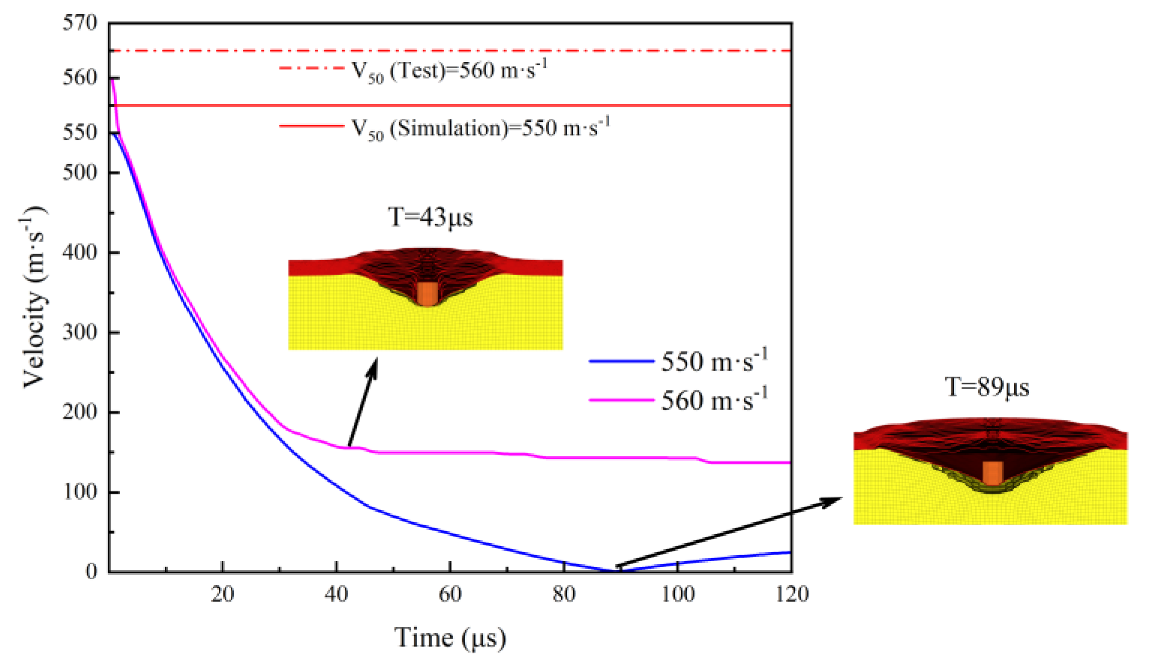
From the results obtained in Table 4, it can be seen that the ballistic limit velocity V50 from both the experiment and the numerical simulation are close, with a discrepancy of only -1.77%. Therefore, it is concluded that the finite element model meets the requirements for subsequent simulation calculations. In addition, the velocity-time curves of the 1.1 g FSP impacting the UHMWPE body armor target plate, with Vblocking=550 m·s-1 and Vpenetration=560 m·s-1 obtained from the numerical simulation, are shown in Figure 2.
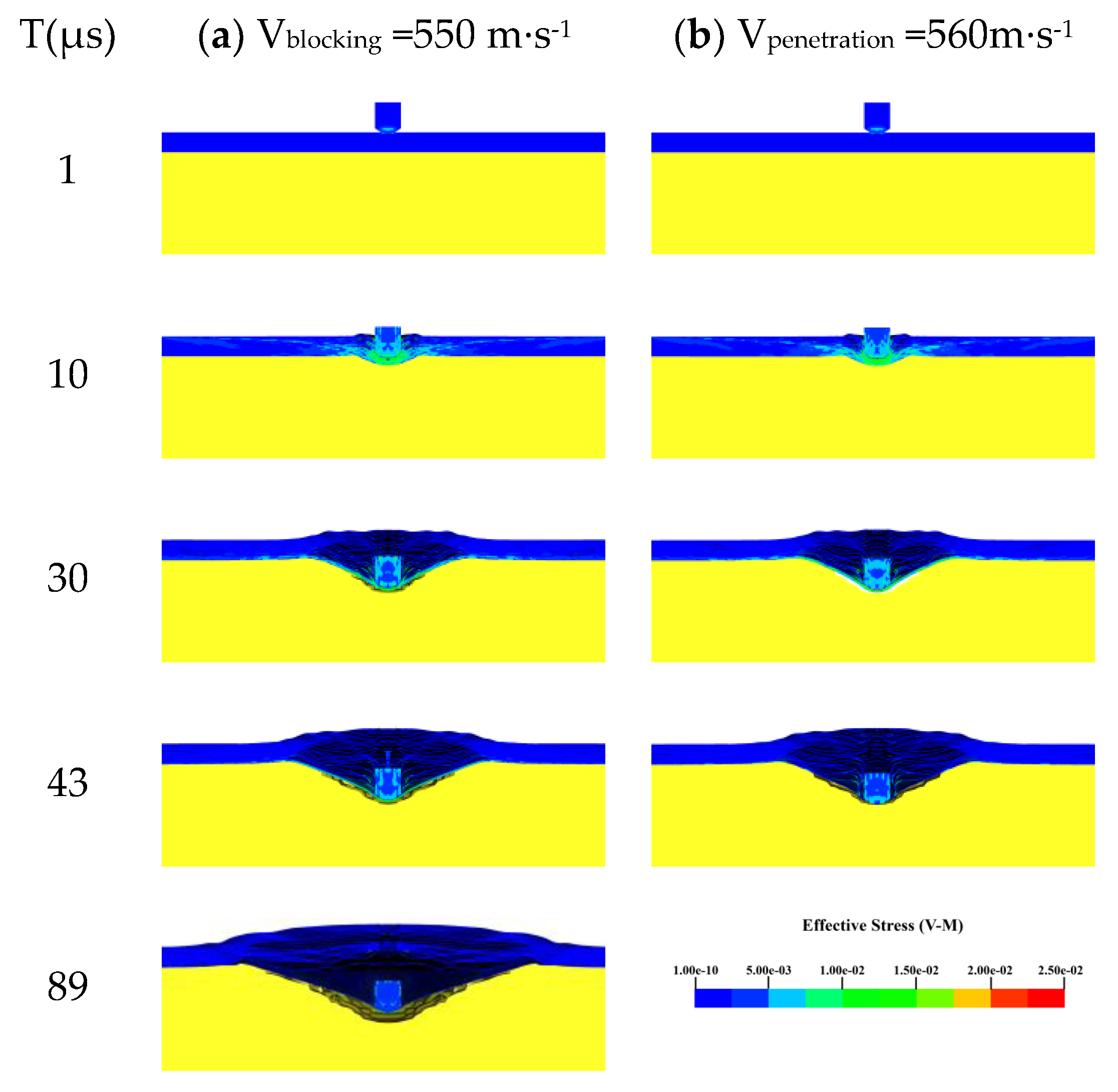
From the velocity-time curves of the fragments in Figure 2, it can be seen that the fragment penetrated the body armor target plate at V=560 m·s-1, while the fragment did not penetrate the target plate and eventually rebounded at V=550 m·s-1. When the fragment’s speed is 550 m·s-1, its velocity rapidly decreases within the first 45 μs and then gradually decreases, reaching zero at t=89 μs and starting to rebound. When the fragment’s speed is 560 m·s-1, its velocity rapidly decreases within the first 30 μs and then gradually decreases, penetrating the target plate at t=43μs and starting to enter the gelatin. Due to the effect of the gelatin, the fragment’s velocity exhibits a small stepwise decrease. Additionally, the Von-Mises stress contour map of the 1.1 g FSP impacting the UHMWPE body armor target plate at Vblocking = 550 m·s-1 and Vpenetration = 560 m·s-1, obtained from the numerical simulation, are shown in Figure 3.
From Figure 3, the FSP did not penetrate the body armor target plate at a speed of 550 m·s-1, whereas penetration occurred at 43 μs when the projectile impacted at 560 m·s-1. The Von-Mises stress contour map indicate that, in both scenarios, the failure of the body armor target plate is almost identical within the first 30 μs. At t=1 μs, the FSP just begins to penetrate the body armor target plate, with only minor stresses appearing at the projectile’s tip and the impact site on the vest. By t=10 μs, the body armor target plate experiences significant stress near the impact site due to the high-speed shearing action of the FSP, causing the initial layers of the target plate to fail rapidly and be penetrated. At t=30 μs, the projectile’s speed decreases and its shearing capability diminishes, causing the unpenetrated layers of the vest to undergo tensile stress, accompanied by significant delamination. At t=43 μs, the FSP at 550 m·s-1 continues to penetrate the body armor target plate, while the projectile at 560 m·s-1 has fully penetrated the vest. At t=89 μs, the speed of the 550 m·s-1 projectile has reduced to zero, with only minor stresses remaining in the fragments and the last unpenetrated layer of the target plate. This indicates that the high-speed penetration of the UHMWPE body armor target plate by the FSP involves three main processes: shearing failure, interlayer delamination, and tensile failure. Given the body armor’s thickness of only 4.124 mm, which is relatively small when being compared to the other two dimensions (X and Y), the deformation and failure in the thickness direction (Z direction) can be considered negligible. The body armor target plate mainly experiences tensile stress in the X and Y directions and shear stress on the XY, ZX, and ZY planes. Therefore, when considering the impact of the elastic modulus and tensile strength on the penetration resistance of the UHMWPE body armor target plate, the elastic modulus and tensile strength in Z direction (thickness direction) can be ignored. This simplification allows the simulation process to focus on adjusting the elastic modulus and tensile strength in X and Y directions without considering Z direction, thereby simplifying the simulation workflow.

4. Results and Discussion

After validating the above numerical model, the material properties (elastic modulus, tensile strength, shear strength) and structural characteristics (number of layers, interlayer strength) of the UHMWPE body armor target plate were going to be studied based on the material properties and structural layout of the validated numerical model to understand their impact mechanisms on the ballistic limit velocity V50.

4.1. The Impact of Material Properties on the V50 of the Body Armor Target Plate

4.1.1. The Impact of Elastic Modulus on the V50 of the Body Armor Target Plate

Elastic modulus is an important parameter that reflects a material’s ability to resist deformation. The greater the elastic modulus, the stronger the material’s resistance to deformation, and vice versa. Therefore, studying the impact mechanism of the elastic modulus on the penetration resistance of the UHMWPE body armor target plate has significant practical importance. Based on the experimentally obtained elastic modulus and referencing the elastic modulus of UHMWPE laminated plate available on the market, E1=E2=30.70 GPa was set as the baseline with reasonable increase and decrease of the elastic modulus in X and Y directions. This approach helps understand the impact mechanism of changes in the elastic modulus in X and Y directions on the body armor’s resistance to penetration by a 1.1 g FSP. The simulation results are shown in Table 5.
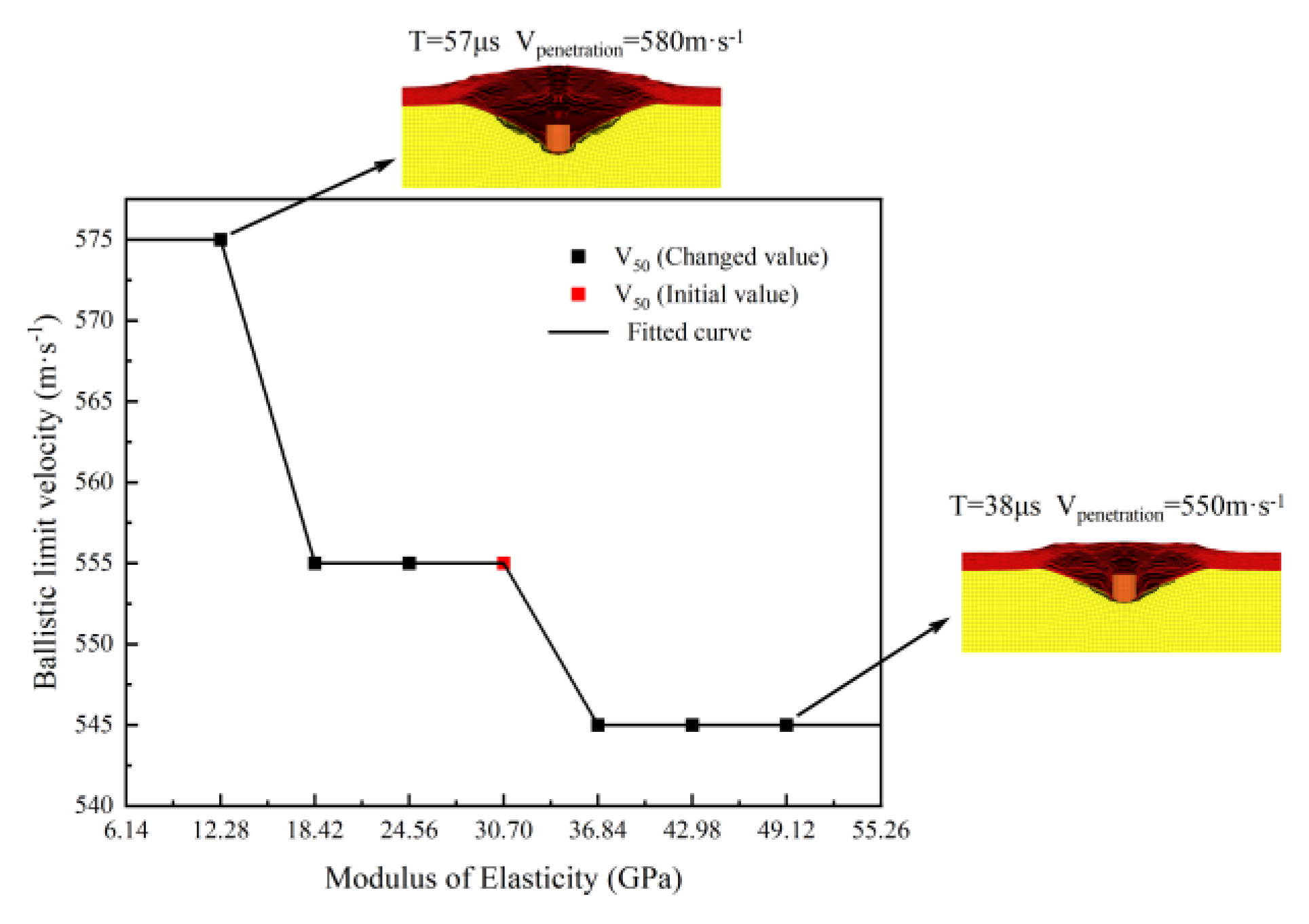
According to the results of the above numerical simulations, when the elastic modulus of the body armor target plate decreases from 30.70 GPa to 12.28 GPa, the ballistic limit velocity V50 increases from 555 m·s-1 to 575 m·s-1, an increase of 3.6%. When the elastic modulus increases from 30.70 GPa to 36.84 GPa, the ballistic limit velocity V50 decreases to 545 m·s-1, a reduction of 1.8%. It is because that as the elastic modulus increases, the body armor target plate becomes harder and more brittle, making it less capable of occurring large deformations and thus more prone to penetration. Conversely, when the elastic modulus decreases, the body armor target plate becomes softer and can undergo substantial elastic deformation, making it relatively harder to penetrate. The rate of change in the ballistic limit velocity V50 with changes in the elastic modulus ranges from -1.8% to 3.6%. Additionally, the trend of the ballistic limit velocity V50 with changes in the elastic modulus is shown in Figure 4.
According to the trend shown in Figure 4, as the elastic modulus of the body armor target plate increases, the ballistic limit velocity V50 tends to decrease. This is like the conclusion reached by Heisserer [26]: with constant strength, increasing the modulus leads to a decrease in the ballistic limit velocity V50, whereas decreasing the elastic modulus results in an increase in the ballistic limit velocity V50. Figure 4 also shows that when the elastic modulus of the body armor target plate is between 18.42 and 30.70 GPa, the ballistic limit velocity V50 remains unchanged. When the elastic modulus continues to decrease below 18.42 GPa, the ballistic limit velocity V50 exhibits a stepwise increase, rising from 555 m·s-1 to 575 m·s-1. Conversely, when the elastic modulus increases above 30.70 GPa, the ballistic limit velocity V50 shows a stepwise decrease, dropping from 555 m·s-1 to 545 m·s-1.By analyzing the failure modes of the body armor target plate at elastic moduli of 12.28 GPa and 49.12 GPa, it can be observed that in both cases, the target plate exhibited significant delamination. However, with a lower elastic modulus, the target plate exhibited a more pronounced tensile deformation capability, allowing its tensile strength to be more fully utilized. Based on this, it can be inferred that materials with a lower elastic modulus might perform better in resisting fragment penetration.
In summary, the change in ballistic limit velocity V50 with elastic modulus is not continuous but more like the segmented changes shown in the fitted function curve in the figure. The ballistic limit velocity V50 only changes accordingly when the elastic modulus increases or decreases to a certain critical value, while minor changes in the elastic modulus have a minimal impact on the ballistic limit velocity V50.

4.1.2. The impact of Tensile Strength on the V50 of the Body Armor Target Plate

Tensile strength is an important parameter for a material’s resistance to tensile failure, especially in the context of high-speed fragment penetration. Excellent tensile strength can play a crucial role in the later stages of penetration. The UHMWPE body armor target plate undergoes three stages during fragment penetration: shear failure, shear plugging, and tensile failure. In the later stages of high-speed fragment penetration, the fragment’s speed decreases, reducing its shear damaging capability on the target plate. At this stage, the UHMWPE layer that has not yet been penetrated is primarily subjected to tensile forces. Strong tensile strength can effectively stop the fragments outside the human body, preventing further injury. Based on the existing tensile strength Xt=Yt=3.10 GPa of the UHMWPE body armor target plate, a reasonable gradient variation by using numerical simulation to study the impact of changes in tensile strength on the ballistic limit V50 of the target plate was made in this paper, and the results are listed in Table 6.
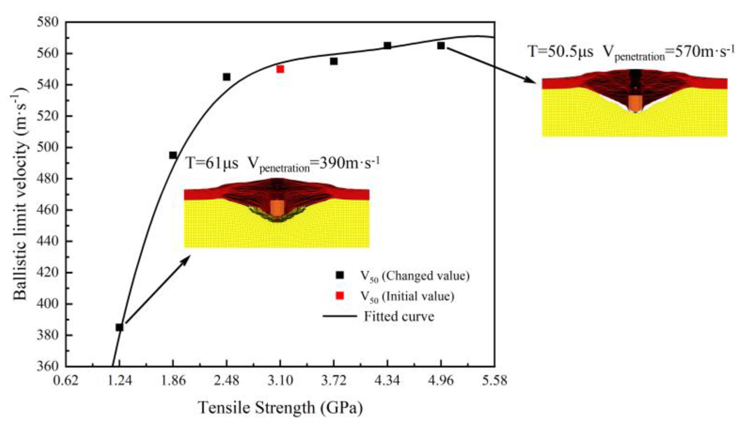
From the ballistic limit velocity V50 results of the 1.1g FSP penetrating the UHMWPE body armor target plate under the above seven sets of tensile strength variations, it can be seen that when the tensile strength decreases from 3.10 GPa to 1.24 GPa, the ballistic limit velocity V50 of the body armor target plate significantly decreases from 555 m·s-1 to 385 m·s-1, a reduction of 30.63%. Conversely, when the tensile strength increases from 3.10 GPa to 4.34 GPa, the ballistic limit velocity V50 increases from 555 m·s-1 to 565 m·s-1, an increase of 1.81%. This indicates that the ballistic limit velocity V50 of the body armor target plate is influenced by its tensile strength. When the tensile strength decreases, the ballistic limit velocity V50 also decreases. However, when the tensile strength increases, the change in the ballistic limit velocity V50 is not significant, with only a slight increase. Further increasing the tensile strength reveals that the ballistic limit velocity V50 of the body armor target plate does not continue to increase accordingly.
From the trend of ballistic limit velocity of the body armor target plate with tensile strength shown in Figure 5, the ballistic limit velocity V50 of the body armor target plate generally shows an upward trend with the increase in tensile strength. When the tensile strength of the body armor target plate is less than 2.48 GPa, the slope of the fitted function curve increases rapidly, and its ballistic limit velocity V50 begins to decrease significantly, indicating a substantial reduction in the penetration resistance of the body armor target plate. When the tensile strength of the body armor target plate exceeds 2.48 GPa, the slope of the fitted function curve gradually levels off, and further increases in tensile strength have an insignificant impact on the ballistic limit velocity V50, resulting in only slight increases. By analyzing the failure modes at tensile strengths of 1.24 GPa and 4.96 GPa, it can be observed that the increase in tensile strength is accompanied by an increase in tensile deformation. This trend shows that as tensile strength increases, the material’s ability to resist tensile failure also correspondingly improves. In the later stages of fragment penetration of the body armor target plate, excellent tensile performance becomes particularly important, as the failure mode of the body armor target plate at this stage primarily manifests as tensile failure. Therefore, the higher the tensile strength, the greater the tensile deformation the material can withstand until the tensile deformation reaches the critical point of failure.
Therefore, when the tensile strength of the body armor target plate significantly decreases, the ballistic limit velocity is very sensitive to changes in tensile strength. At this stage, the body armor target plate primarily fails due to tensile failure. Conversely, when the tensile strength of the body armor target plate increases, the change in ballistic limit velocity V50 is not significant. The reason for this is that at this stage, the primary failure mode of the body armor target plate is shear failure. Further increasing the tensile strength of the body armor target plate has minor impact on its penetration resistance, because the target plate experiences shear failure and penetration before reaching its tensile limit, which also explains the results obtained in Table 6.

4.1.3. The Impact of Shear Strength on the V50 of The Body Armor Target Plate

Shear strength refers to the ability of a material to resist shear failure. The greater the shear strength, the stronger its ability to resist shear failure, and vice versa. Excellent shear strength plays a crucial role in the field of high-speed fragment penetration. When an FSP penetrates a body armor target plate, the high initial velocity of the fragment results in extraordinarily strong shear capability. At this moment, the excellent shear performance of the body armor target plate will significantly dissipate the kinetic energy of the FSP, greatly reducing its speed. As mentioned in the previous section, excellent shear strength is also a prerequisite for tensile strength to be effective. Only after the shear strength has dissipated most kinetic energy of the FSP can the excellent tensile strength of the body armor target plate be manifested. Therefore, shear strength is critical to the ballistic limit velocity V50 of the body armor target plate. The impact of changes in shear strength on ballistic limit velocity V50 is shown in Table 7.
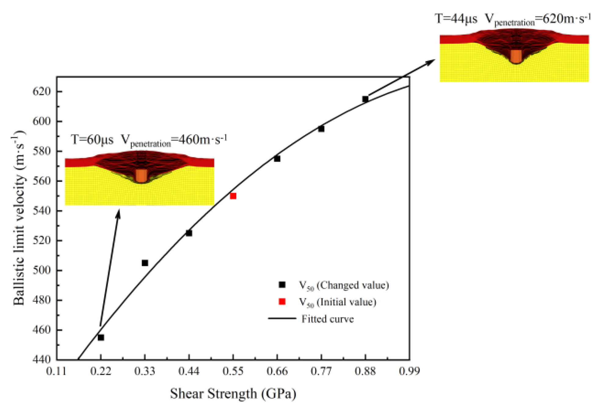
From the above 7 sets of data, it can be concluded that when the shear strength decreases from 0.55 GPa to 0.22 GPa, the ballistic limit velocity V50 of the body armor target plate decreases from 550 m·s-1 to 455 m·s-1, a decrease of 18.02%. When the shear strength increases from 0.55 GPa to 0.88 GPa, the ballistic limit velocity V50 increases from 555 m·s-1 to 615 m·s-1, an increase of 10.81%. The influence of shear strength on the ballistic limit velocity V50 of the body armor target plate is quite significant. The ballistic limit velocity V50 changes with the shear strength; when the shear strength decreases, the ballistic limit velocity V50 also decreases, and vice versa.
From the trend of the ballistic limit velocity V50 with shear strength shown in Figure 6, it can be seen that as the shear strength of the body armor target plate increases, its ballistic limit velocity V50 generally shows an upward trend, which is exactly the opposite of the results obtained by Karthikeyan et al. [38]. The reason may be that the UHMWPE plate studied by Karthikeyan et al. was relatively thick, whereas, for thinner plate, shear strength becomes the main cause of failure. Additionally, the inconsistency in results might also be influenced by the matrix material. As can also be seen from the failure morphology of the body armor target plate at shear strengths of 0.22 GPa and 0.88 GPa in Figure 6, the tensile deformation of the body armor target plate at a shear strength of 0.88 GPa is slightly greater than at 0.22 GPa. This indirectly proves that excellent shear strength is a sufficient condition for the tensile strength to take effect.
Why shear strength, unlike tensile strength, does not have a diminishing effect on ballistic limit velocity V50 after increasing to a certain extent is that shear strength is the first property to take effect in the penetration resistance process of the body armor target plate. When a fragment penetrates the body armor target plate, it is extremely high initial velocity results in strong shearing capability. The body armor target plate undergoes shear failure due to the strong shearing damage caused by the high-speed fragment. At this time, shear failure occurs before tensile failure because the body armor target plate does not undergo significant tensile deformation when the high-speed fragment penetrates it, thus tensile failure cannot occur first. Therefore, as shear strength increases, the penetration resistance of the body armor target plate also increases, which is unlike tensile strength maintaining a constant effect after reaching a certain level. Hence, the excellent shear strength of the body armor target plate is crucial for its penetration resistance performance.

4.2. The Impact of Structural Characteristics on the V50 of the Body Armor Target Plate

The structural characteristics of body armors are equally important to their ballistic limit velocity V50. With carefully designed structural layouts, body armors can further improve their penetration resistance while maintaining lightness and comfort. Therefore, this section reasonably varies the number of layers and the interlayer bonding strength of the body armor target plate to study the impact mechanism of these structural characteristics on its ballistic limit velocity V50.

4.2.1. The Impact of the Number of Layers on the V50 of the Body Armor Target Plate

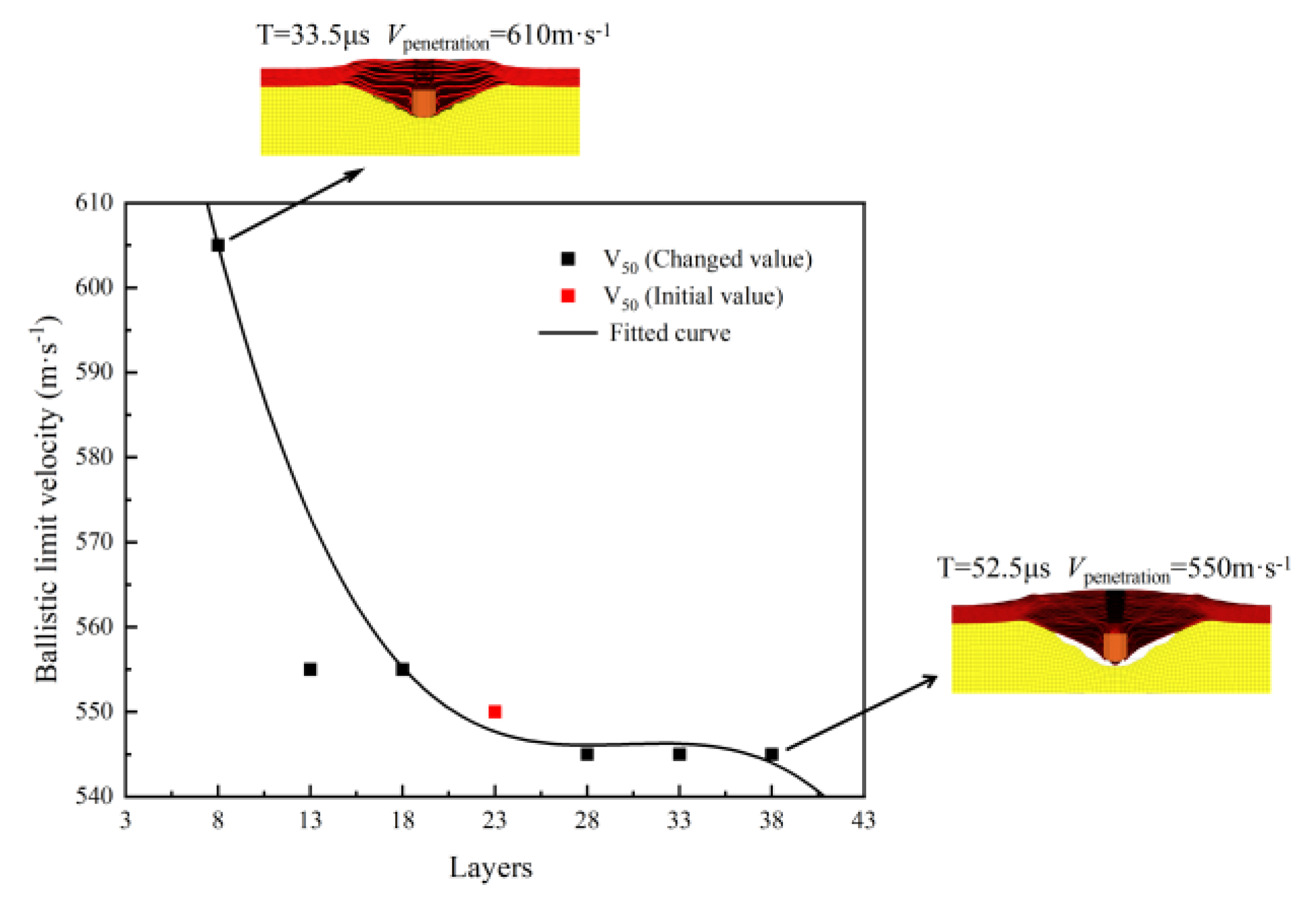
Based on the original body armor target plate model (23 layers, total thickness 4.124 mm), several other finite element models of body armor target plates with the same thickness but different numbers of layers were established. Finite element simulations were performed on each of these models, and the ballistic limit velocity V50 results for body armor target plates with the same thickness but different numbers of layers were obtained and listed in Table 8.
According to the results in Table 8, when the number of layers is reduced from 23 to 13 or 18, the ballistic limit velocity V50 does not change. However, when the number of layers is further reduced to 8, the ballistic limit velocity V50 significantly increases from 555 m·s-1 to 605 m·s-1, with an increase of 9.01%. On the other hand, when the number of layers is increased from 23 to 28, the ballistic limit velocity V50 decreases from 555 m·s-1 to 545 m·s-1, with a decrease of 1.80%. When the number of layers continues to increase, the ballistic limit velocity V50 dose no longer changed. This indicates that increasing the number of layers beyond the original number has a very minimal impact on the ballistic limit velocity V50, while appropriately reducing the number of layers can improve the ballistic limit velocity V50.
From the trend of the ballistic limit velocity V50 of the body armor target plates with respect to the number of layers in Figure 7, it can be seen that when the total thickness of the body armor target plate remains unchanged, the ballistic limit velocity V50 generally shows a decreasing trend as the number of layers increases. The fitted function curve shows that when the number of layers in the body armor target plate is above 13, the change in ballistic limit velocity is not significant. However, when the number of layers decreases to below 13, the ballistic limit velocity V50 increases significantly.
By comparing differences in damage patterns between body armor target plates of 8 layers and 38 layers, it can be observed that tensile deformation is not significant in both cases, indicating that shear failure is the dominant failure mechanism in these situations. With the total thickness kept constant, as the number of layers increases, the thickness of each layer decreases correspondingly, leading to a significant reduction in the shear resistance of each layer. This structural weakness allows high-speed fragments to penetrate each layer of the target plate relatively easily. Conversely, when the number of layers in the body armor target plate is significantly reduced, the thickness of each layer increases correspondingly, thereby enhancing the shear resistance of each layer. This enhanced shear performance effectively slows down the velocity of the fragments in the initial penetration stage, reducing their ability to penetrate subsequent layers. Therefore, the ballistic limit velocity V50 of body armor target plates significantly increases when the number of layers is reduced.
In summary, when the total thickness remains constant, a smaller number of layers can improve the shear resistance of the structure, thereby enhancing the overall protective performance of the body armor target plate, leading to an increase in the ballistic limit velocity V50. This conclusion is slightly different from that of Zhang et al. [39], possibly because the total thickness of the laminated plates in their study was much greater than the thickness of the body armor target plates provided in this study. When the number of layers increases, the thickness of each target plate layer does not excessively small, so the shear resistance of each layer remains relatively high, leading to different results. Additionally, their study considered the cross-laminated structure of UHMWPE, which might be another reason explaining the difference. Therefore, when the total thickness of the body armor target plate is relatively thin, having too many layers can reduce its penetration resistance.

4.2.2. The Impact of Interlayer Strength on the V50 of the Body Armor Target Plate

The above studies respectively examined the effects of the material properties and the number of layers of body armor target plates on their ballistic limit velocity V50. When considering the above factors, the bonding between the layers of the body armor target plates was not taken into account, so the contact between each layer of the target plates was set to *CONTACT_AUTOMATIC_SURFACE_TO_SURFACE. This section studies the effect of interlayer strength of body armor target plates on their ballistic limit velocity V50. Therefore, the contact between each layer of the target plates was changed to *CONTACT_AUTOMATIC_SURFACE_TO_SURFACE_TIEBREAK, which allowed for the failure of the bonded interface between the two contacting surfaces during the contact process. The interlayer failure criterion is shown in equation 10, where NFLS and SFLS represent the interlayer normal strength and the interlayer shear strength, respectively [40], σn and σs represent the normal failure stress and shear failure stress of the adhesive layer, respectively. The parameters of normal and interlayer shear strength [41] are shown in Table 9. Based on the above interlayer failure strength, the impact of changes in interlayer strength on the ballistic limit velocity V50 of the body armor target plates was studied.
| σ n | N F L S 2 + | σ s | S F L S 2 1
When the interlayer failure strength shown in Table 9 is added to the body armor target plate in the finite element model, the ballistic limit velocity V50 of the body armor target plate decreases from 555 m·s-1 to 525 m·s-1, a reduction of 5.41%. Additionally, the damage process diagrams of the body armor target plates in both cases (without interlayer bonding and with the interlayer strength shown in Table 9) are presented in Figure 8.
From Figure 8, the damage process of body armor target plates with and without interlayer strength shows that the presence or absence of interlayer bonding has little effect on the shear failure of the body armor target plates, with both exhibiting similar damage forms within the first 20 μs. When the fragments continue to penetrate and reach 30 μs, delamination of the body armor target plates begins to occur. At this point, the body armor target plates without interlayer bonding exhibit more pronounced delamination and slightly greater back deformation compared to the body armor target plates with interlayer strength (NFLS = 55 MPa, SFLS = 120 MPa). At 43 μs, both types of plates are penetrated, with the delamination and back deformation of the non-bonded body armor target plates being significantly greater than those with the interlayer strength (NFLS = 55 MPa, SFLS = 120 MPa). In the later stages of fragment penetration, the non-bonded body armor target plates exhibit more significant delamination and greater tensile deformation. Therefore, the ballistic limit velocity V50 of the non-bonded body armor target plates is higher than that of the body armor target plates with the above interlayer strength (NFLS = 55 MPa, SFLS = 120 MPa).
Based on the above results, interlayer strength has a certain impact on the ballistic limit velocity V50 of body armor target plates. Therefore, based on the interlayer strengths listed in Table 9, the interlayer normal strength and interlayer shear strength are proportionally varied to explore the impact of interlayer strength changes on the ballistic limit velocity V50 of body armor target plates.
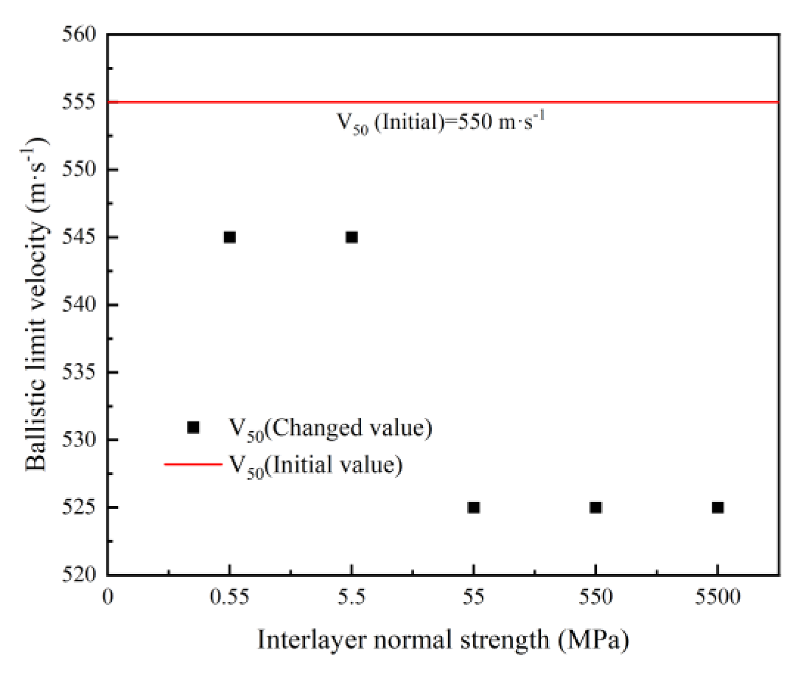
First, the interlayer normal strength is proportionally varied while keeping the interlayer shear strength constant, and the results obtained from numerical simulations are listed in Table 10.
From Table 10, it can be seen that when the interlayer normal strength of the body armor target plate is 0.55 MPa and the interlayer shear strength is 120 MPa, the ballistic limit velocity V50 of the body armor target plate decreases from 555 m·s-1 to 545 m·s-1, a reduction of 1.80%. When the interlayer normal strength is 5500 MPa and the interlayer shear strength is 120 MPa, the ballistic limit velocity V50 decreases from 555 m·s-1 to 525 m·s-1, a reduction of 5.41%.
From Figure 9, it can be observed that the ballistic limit velocity V50 of the body armor target plate decreases gradually with the increase in interlayer normal strength. Moreover, the ballistic limit velocity V50 of all body armor target plates with the interlayer strength values listed in Table 10 is lower than that of the body armor target plates without interlayer bonding.
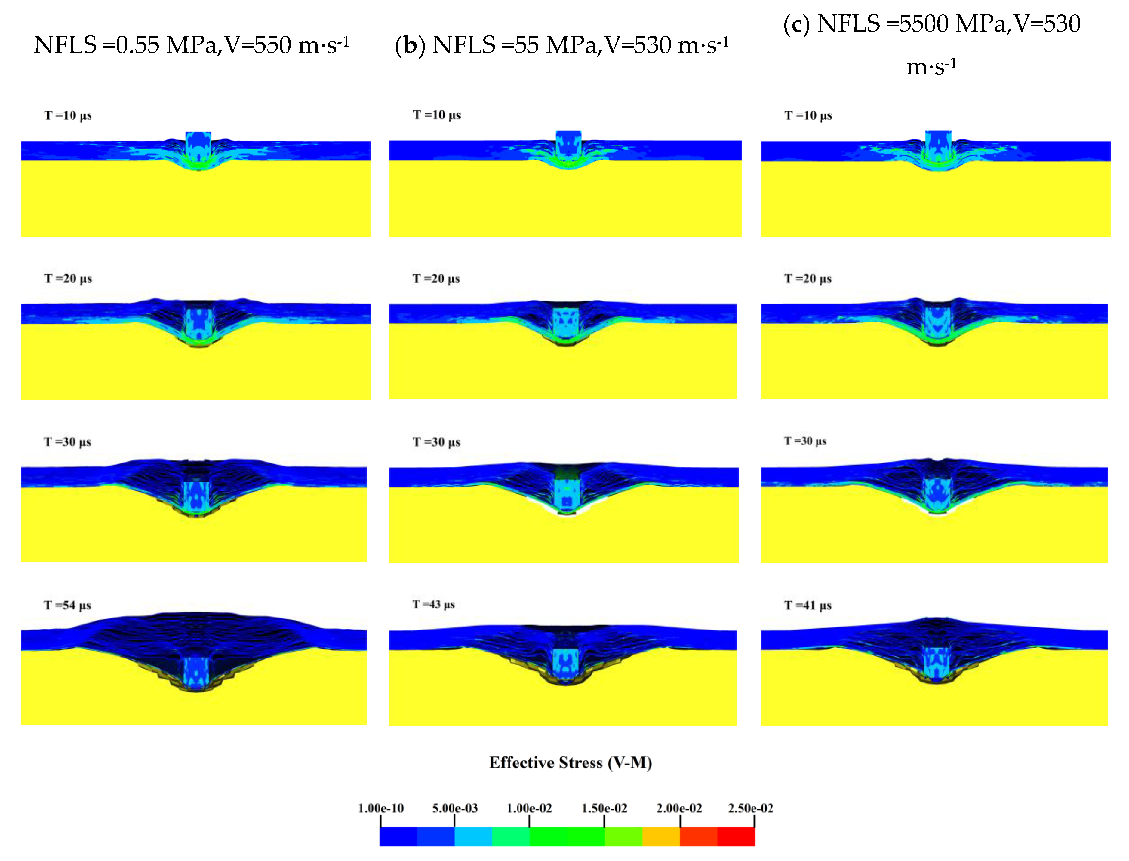
To further determine the effect of the interlayer normal strength on the ballistic limit velocity V50 of the body armor target plate, the Von-Mises stress cloud diagrams for NFLS values of 0.55, 55, and 5500 MPa when SFLS is 120 MPa are shown in Figure 10. The penetration process is analyzed accordingly.
From the Von-Mises stress cloud diagrams in Figure 10 for NFLS values of 0.55, 55, and 5500 MPa, it can be seen that during the initial 20 μs, the failure modes of the body armor target plates for the three interlayer strengths are essentially the same, all exhibiting shear failure with similar stress levels. When penetration continues up to 30 μs, the delamination and back deformation of the target plates differ due to the varying interlayer normal strengths. At an NFLS of 0.55 MPa, the delamination and back deformation of the body armor target plate are significantly greater than at NFLS values of 55 MPa and 5500 MPa. For NFLS values of 55 MPa and 5500 MPa, the failure modes of the body armor target plates are the same at large. Thus, it can be concluded that once the interlayer normal strength of the body armor target plate increases beyond a certain range, further increases in interlayer normal strength have a minimal impact on the ballistic limit velocity V50.
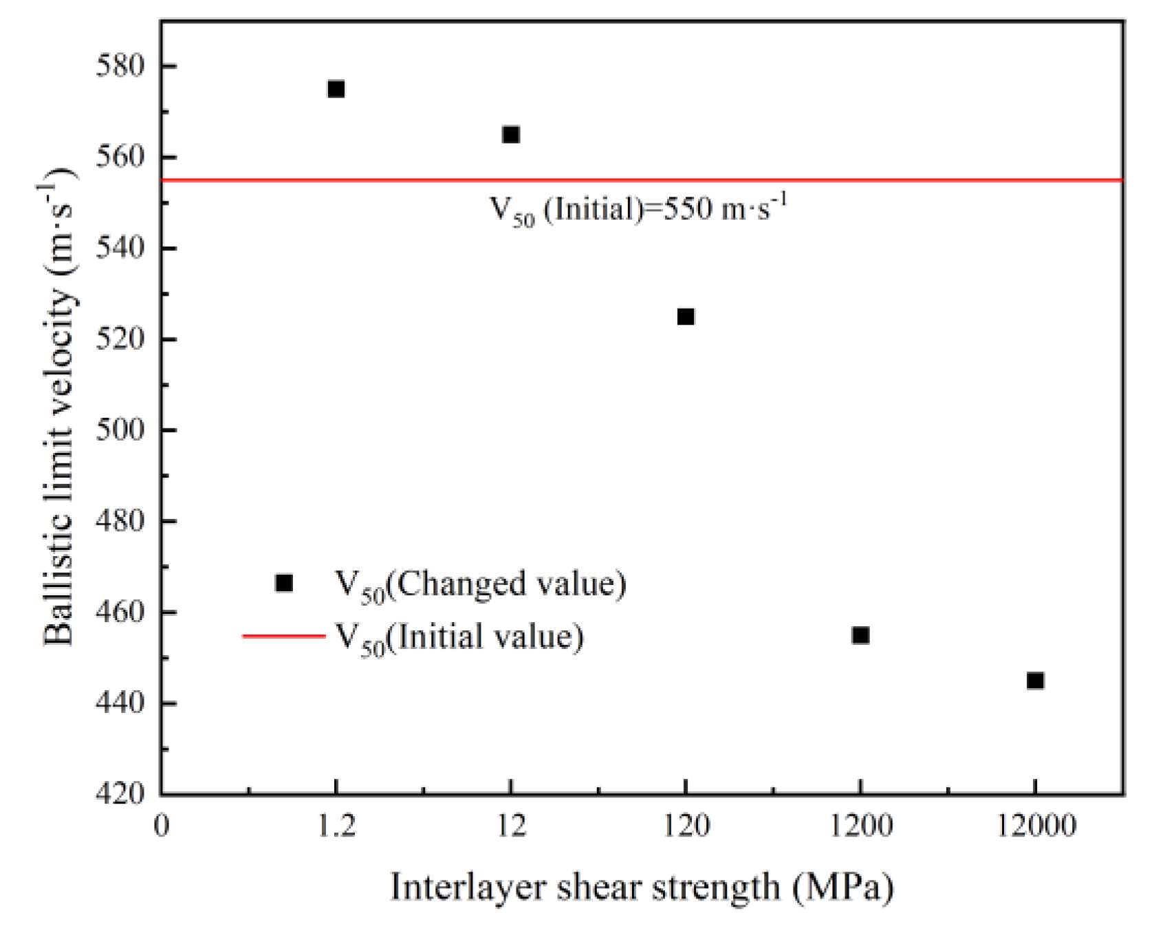
After analyzing the effect of interlayer normal strength on the ballistic limit velocity V50 of the body armor target plate, the focus shifts to studying the effect of interlayer shear strength on the ballistic limit velocity V50 of the body armor target plate. By keeping the interlayer normal strength constant (NFLS = 55 MPa) and proportionally varying the interlayer shear strength, the influence of changes in interlayer shear strength on the ballistic limit velocity V50 of the body armor target plate is studied. The obtained results are presented in Table 11.
From Table 11, when the interlayer shear strength is 1.2 MPa and the interlayer normal strength is 55 MPa, the ballistic limit velocity V50 of the body armor target plate increases from 555 m·s-1 to 575 m·s-1, with an increase of 3.60%. Conversely, when the interlayer shear strength is 12,000 MPa and the interlayer normal strength is 55 MPa, the ballistic limit velocity V50 decreases from 555 m·s-1 to 445 m·s-1, with a decrease of 19.82%.
From the trend in Figure 11 showing the ballistic limit velocity with changes in interlayer shear strength, when the interlayer shear strength of the body armor target plate is 1.2 or 12 MPa, its ballistic limit velocity V50 is greater than that of the target plate without interlayer bonding. However, as the interlayer shear strength continues to increase, the ballistic limit velocity V50 becomes lower than that of the target plate without interlayer bonding. Additionally, the ballistic limit velocity V50 of the body armor target plate tends to decrease with increasing interlayer shear strength.
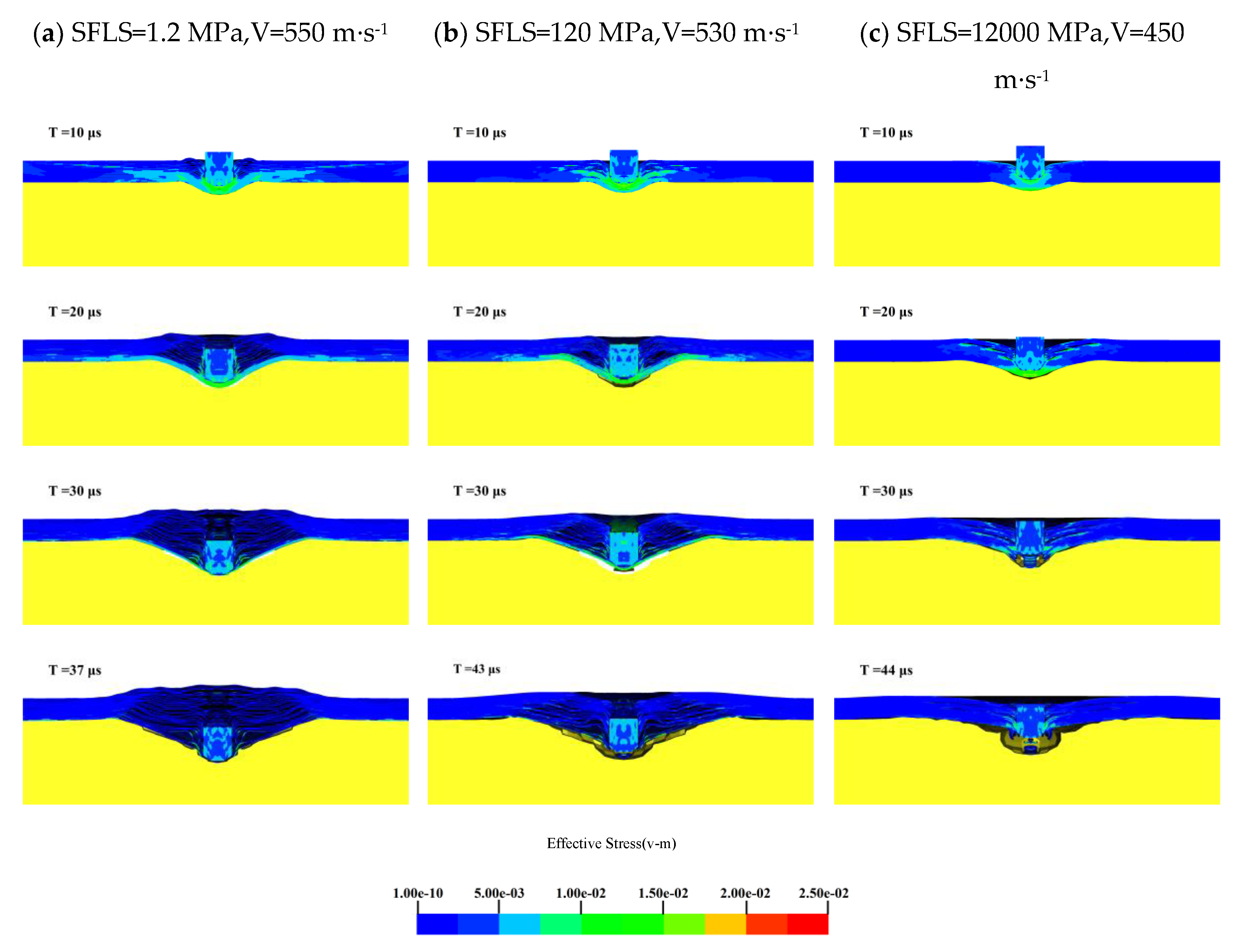
To further determine the effect of interlayer shear strength on the ballistic limit velocity V50 of the body armor target plate, the Von-Mises stress cloud diagrams for SFLS values of 1.2, 120, and 12,000 MPa when NFLS is 55 MPa are shown in Figure 12. The penetration process is analyzed accordingly.
From the Von-Mises stress cloud diagrams in Figure 12 for SFLS values of 1.2, 120, and 12,000 MPa, as the interlayer shear strength of the body armor target plate increases, delamination and tensile deformation significantly decrease. At an SFLS of 1.2 MPa, the body armor target plate primarily experiences shear failure in the first 20 μs, significant tensile deformation at 30 μs, and penetration by 37 μs. When SFLS is 120 MPa, the failure mode of the body armor target plate is essentially the same as at 1.2 MPa, but both delamination and tensile deformation are less than at 1.2 MPa. At an SFLS of 12,000 MPa, the failure mode of the body armor target plate is completely different from the previous two; the plate mainly undergoes shear failure and shear plugging with almost no interlayer delamination or tensile deformation. At this point, the failure mode of the body armor target plate is like that of a single-layer plate of the same thickness.
In summary, the interlayer strength of the body armor target plate has a significant impact on its ballistic performance, with the effect of interlayer shear strength being much greater than that of interlayer normal strength. When the body armor target plate has appropriate interlayer strength, the delamination between the layers can also dissipate part of the projectile’s kinetic energy, making it more difficult to penetrate the target plate. However, if the interlayer strength is too high, the body armor target plate behaves like a single-layer plate of the same thickness, and its failure mode is entirely different from that of a multi-layered structure. In this case, the primary causes of failure are shear failure and shear plugging, with almost no delamination or tensile deformation occurring [42]. Therefore, determining the appropriate interlayer strength between the layers of the body armor target plate is crucial for enhancing its ballistic performance.

5. Conclusions

In this study, investigation for penetration mechanism of a 1.1g FSP into a body armor target plate is made. Based on such investigation, the impact of the material properties and structural characteristics of the body armor target plate on its ballistic limit velocity is considered, leading to the following conclusions:
(1) A numerical model was established for the penetration of a 1.1g FSP into a UHMWPE body armor target plate, by which numerical simulations reveal that during the penetration process, the body armor target plate undergoes three stages: shear failure, interlayer delamination, and tensile failure. The projectile’s velocity decreases most rapidly, and its kinetic energy is most dissipated during the early stages of penetration.
(2) The material properties of the body armor target plate significantly affect its ballistic limit velocity. The effects of the elastic modulus, tensile strength, and shear strength of the body armor target plate on its ballistic limit velocity is examined in this study. Among these, the ballistic limit velocity is most sensitive to changes in shear strength, with a variation rate ranging from -18.02% to 10.81%, showing an approximately positive correlation between them. Changes in the elastic modulus have the smallest impact on the ballistic limit velocity V50, with a variation rate between -1.8% and 3.6%.
(3) The structural characteristics of the body armor target plate also have a significant impact on its ballistic performance. When the number of layers in the body armor target plate is reduced from 23 to 8, its ballistic limit velocity increases by 9.01%. Conversely, when the number of layers increases from 23 to 38, its ballistic limit velocity decreases by 1.8%. When considering the impact of the interlayer strength, the interlayer shear strength has the most significant impact on the ballistic limit velocity V50 of the body armor target plate. Appropriate interlayer strength can improve the ballistic limit velocity, while excessively high interlayer shear strength causes the body armor target plates to be over bonded, resulting in a failure mode similar to that of a single-layer plate of the same thickness, greatly reducing its penetration resistance.
Author Contributions

Conceptualization, K.D. and Y.Z.; methodology, K.D. and Y.Z.; validation, J.B. and X.L.; writing—original draft preparation, J.B.; data curation, J.B.; validation, Z.H. and G.W.; visualization, Z.H. and G.W.; writing—review and editing, J.B.; All authors have read and agreed to the published version of the manuscript.

Institutional Review Board Statement

Not applicable.

Data Availability Statement

Data are contained within the article.

Conflicts of Interest

The authors declare no conflicts of interest.

References

  1. Caister, A.J.; Carr, D.J.; Campbell, P.D.; Brock, F.; Breeze, J. The Ballistic Performance of Bone When Impacted by Fragments. Int. J. Leg. Med. 2020, 134, 1387–1393. [CrossRef]
  2. Breeze, J.; Hunt, N.; Gibb, I.; James, G.; Hepper, A.; Clasper, J. Experimental Penetration of Fragment Simulating Projectiles into Porcine Tissues Compared with Simulants. J. Forensic Leg. Med. 2013, 20, 296–299. [CrossRef]
  3. Gama, B.A.; Gillespie, J.W. Finite Element Modeling of Impact, Damage Evolution and Penetration of Thick-Section Composites. Int. J. Impact Eng. 2011, 38, 181–197. [CrossRef]
  4. Reddy, P.R.S.; Reddy, T.S.; Madhu, V.; Gogia, A.K.; Rao, K.V. Behavior of E-Glass Composite Laminates under Ballistic Impact. Mater. Design 2015, 84, 79–86. [CrossRef]
  5. Gama, B.A.; Islam, S.W.; Rahman, M.; Gillespie Jr, J.W.; Bogetti, T.A.; Cheeseman, B.A.; Yen, C.-F.; Hoppel, C.P. Punch Shear Behavior of Thick-Section Composites under Quasi-Static, Low Velocity, and Ballistic Impact Loading. SAMPE J 2005, 41, 6–13.
  6. Gellert, E.P.; Cimpoeru, S.J.; Woodward, R.L. A Study of the Effect of Target Thickness on the Ballistic Perforation of Glass-Fibre-Reinforced Plastic Composites. Int. J. Impact Eng. 2000, 24, 445–456. [CrossRef]
  7. Karthikeyan, K.; Russell, B.P.; Fleck, N.A.; O’Masta, M.; Wadley, H.N.G.; Deshpande, V.S. The Soft Impact Response of Composite Laminate Beams. Int. J. Impact Eng. 2013, 60, 24–36. [CrossRef]
  8. Wicklein, M.; Ryan, S.; White, D.M.; Clegg, R.A. Hypervelocity Impact on CFRP: Testing, Material Modelling, and Numerical Simulation. Int. J. Impact Eng. 2008, 35, 1861–1869. [CrossRef]
  9. Yashiro, S.; Ogi, K.; Yoshimura, A.; Sakaida, Y. Characterization of High-Velocity Impact Damage in CFRP Laminates: Part II – Prediction by Smoothed Particle Hydrodynamics. Compos. A: Appl. Sci. Manuf. 2014, 56, 308–318. [CrossRef]
  10. Shim, V.P.W.; Guo, Y.B.; Tan, V.B.C. Response of Woven and Laminated High-Strength Fabric to Oblique Impact. Int. J. Impact Eng. 2012, 48, 87–97. [CrossRef]
  11. Tham, C.Y.; Tan, V.B.C.; Lee, H.P. Ballistic Impact of a KEVLAR® Helmet: Experiment and Simulations. Int. J. Impact Eng. 2008, 35, 304–318. [CrossRef]
  12. Sanborn, B.; Weerasooriya, T. Quantifying Damage at Multiple Loading Rates to Kevlar KM2 Fibers Due to Weaving, Finishing, and Pre-Twist. Int. J. Impact Eng. 2014, 71, 50–59. [CrossRef]
  13. Katz, S.; Grossman, E.; Gouzman, I.; Murat, M.; Wiesel, E.; Wagner, H.D. Response of Composite Materials to Hypervelocity Impact. Int. J. Impact Eng. 2008, 35, 1606–1611. [CrossRef]
  14. Tan, V.B.C.; Khoo, K.J.L. Perforation of Flexible Laminates by Projectiles of Different Geometry. Int. J. Impact Eng. 2005, 31, 793–810. [CrossRef]
  15. Koh, A.C.P.; Shim, V.P.W.; Tan, V.B.C. Dynamic Behaviour of UHMWPE Yarns and Addressing Impedance Mismatch Effects of Specimen Clamps. Int. J. Impact Eng. 2010, 37, 324–332. [CrossRef]
  16. Russell, B.P.; Karthikeyan, K.; Deshpande, V.S.; Fleck, N.A. The High Strain Rate Response of Ultra High Molecular-Weight Polyethylene: From Fibre to Laminate. Int. J. Impact Eng. 2013, 60, 1–9. [CrossRef]
  17. Vargas-Gonzalez, L.R.; Gurganus, J.C. Hybridized Composite Architecture for Mitigation of Non-Penetrating Ballistic Trauma. Int. J. Impact Eng. 2015, 86, 295–306. [CrossRef]
  18. Karahan, M. Comparison of Ballistic Performance and Energy Absorption Capabilities of Woven and Unidirectional Aramid Fabrics. Text. Res. J. 2008, 78, 718–730. [CrossRef]
  19. Zhang, D.; Sun, Y.; Chen, L.; Zhang, S.; Pan, N. Influence of Fabric Structure and Thickness on the Ballistic Impact Behavior of Ultrahigh Molecular Weight Polyethylene Composite Laminate. Mater. Des. (1980-2015) 2014, 54, 315–322. [CrossRef]
  20. Karahan, M.; Jabbar, A.; Karahan, N. Ballistic Impact Behavior of the Aramid and Ultra-High Molecular Weight Polyethylene Composites. Journal of Reinforced Plastics and Composites 2015, 34, 37–48. [CrossRef]
  21. Nguyen, L.H.; Ryan, S.; Cimpoeru, S.J.; Mouritz, A.P.; Orifici, A.C. The Effect of Target Thickness on the Ballistic Performance of Ultra High Molecular Weight Polyethylene Composite. International Journal of Impact Engineering 2015, 75, 174–183. [CrossRef]
  22. Cao, M.; Chen, L.; Xu, R.; Fang, Q. Effect of the Temperature on Ballistic Performance of UHMWPE Laminate with Limited Thickness. Compos. Struct. 2021, 277, 114638. [CrossRef]
  23. Meshi, I.; Amarilio, I.; Benes, D.; Haj-Ali, R. Delamination Behavior of UHMWPE Soft Layered Composites. Compos. B: Eng. 2016, 98, 166–175.
  24. Chen, L.; Zheng, K.; Fang, Q. Effect of Strain Rate on the Dynamic Tensile Behaviour of UHMWPE Fibre Laminates. Polym. Test. 2017, 63, 54–64. [CrossRef]
  25. Lässig, T.; Riedel, W.; Heisserer, U.; Van Der Werff, H.; May, M.; Hiermaier, S. Numerical Sensitivity Studies of a UHMWPE Composite for Ballistic Protection.; New Forest, UK, June 3 2014; pp. 371–381.
  26. Heisserer, U.; Van der Werff, H. The Relation between Dyneema® Fiber Properties and Ballistic Protection Performance of Its Fiber Composites. In Proceedings of the 15th International conference on deformation, yield and fracture of polymers; 2012; Vol. 3, pp. 242–246.
  27. Zhang, R.; Han, B.; Zhou, Y.; Qiang, L.-S.; Zhao, C.-Z.; Zhao, Z.-Y.; Zhang, Q.-C.; Ju, Y.-Y.; Lu, T.J. Mechanism-Driven Analytical Modelling of UHMWPE Laminates under Ballistic Impact. Int. J. Mech. Sci. 2023, 245, 108132. [CrossRef]
  28. Karthikeyan, K.; Russell, B.P. Polyethylene Ballistic Laminates: Failure Mechanics and Interface Effect. Mater. Design 2014, 63, 115–125. [CrossRef]
  29. Heisserer, U.; Van der Werff, H.; Hendrix, J. Ballistic Depth of Penetration Studies in Dyneema® Composites. In Proceedings of the 27th International symposium on ballistics; 2013; pp. 1936–1943.
  30. Shen, Y.; Wang, Y.; Yan, Z.; Cheng, X.; Fan, Q.; Wang, F.; Miao, C. Experimental and Numerical Investigation of the Effect of Projectile Nose Shape on the Deformation and Energy Dissipation Mechanisms of the Ultra-High Molecular Weight Polyethylene (UHMWPE) Composite. Materials 2021, 14, 4208. [CrossRef]
  31. Xie, Y.; Zhang, H.; Zhu, W.; Huang, G. Effects of Textile Structure and Projectile Geometry on Ballistic Performance of UHMWPE Textiles. Compos. Struct. 2022, 279, 114785. [CrossRef]
  32. Gilson, L.; Rabet, L.; Imad, A.; Coghe, F. Experimental and Numerical Assessment of Non-Penetrating Impacts on a Composite Protection and Ballistic Gelatine. International Journal of Impact Engineering 2020, 136, 103417. [CrossRef]
  33. Lin, J.; Li, Y.; Liu, S.; Fan, H. Numerical Investigation of the High-Velocity Impact Performance of Body Armor Panels. Thin. Wall. Struct. 2023, 189, 110909. [CrossRef]
  34. Hu NM; Chen CH; Hou HL; Zhu X Simulation on damage characteristic of composite laminates under high-velocity projectile impact. Ordnance Material Science and Engineering 2017, 40, 66–70. [CrossRef]
  35. Liu, P.; Liu, Y.; Wang, Z.; Chen, J.; Zhang, H.; Huang, G. A Design Model of Multi-Layer Modified Aramid Fabrics against Fragment Simulating Projectiles and Full Metal Jacketed Bullets. Int. J. Impact Eng. 2024, 191, 104989. [CrossRef]
  36. SUN Fei; MA L.; ZHU Y.; XU C. Numerical analysis for impact effects of a pistol bullet on a gelatin target covered with UHMWPE fiber armor. Journal of Vibration and Shock 2018, 37, 20–26. [CrossRef]
  37. GB/T 32497-2016: Test Method for Simulating the Ballistic Performance of Fiber Reinforced Composites against Fragmentation Projectiles: V50 Method [S]. Standards Press of China: Beijing, China, 2016.
  38. Karthikeyan, K.; Russell, B.P.; Fleck, N.A.; Wadley, H.N.G.; Deshpande, V.S. The Effect of Shear Strength on the Ballistic Response of Laminated Composite Plates. Eur. J. Mech. A. Solids 2013, 42, 35–53. [CrossRef]
  39. Zhang, R.; Han, B.; Zhong, J.-Y.; Qiang, L.-S.; Ni, C.-Y.; Zhang, Q.; Zhang, Q.-C.; Li, B.-C.; Lu, T.J. Enhanced Ballistic Resistance of Multilayered Cross-Ply UHMWPE Laminated Plates. Int. J. Impact Eng. 2022, 159, 104035. [CrossRef]
  40. Zhi-yong Li; You-song Xue; Bao-zhong Sun; Bo-hong Gu Ballistic penetration damages of hybrid plain-woven laminates with carbon, Kevlar and UHMWPE fibers in different stacking sequences. Defence Technology 2023, 26, 23–38. [CrossRef]
  41. Luo X.; WEN YK; YAN WM; Dong YF; Dong Fangdong Numerical simulation of spherical fragment penetrating UHMWPE soft body armor based on ABAQUS. Acta Materiae Compositae Sinica 2021, 38, 3373–3386. [CrossRef]
  42. Zhang, R.; Qiang, L.-S.; Han, B.; Zhao, Z.-Y.; Zhang, Q.-C.; Ni, C.-Y.; Lu, T.J. Ballistic Performance of UHMWPE Laminated Plates and UHMWPE Encapsulated Aluminum Structures: Numerical Simulation. Composite Structures 2020, 252, 112686. [CrossRef]
Figure 2. The velocity time history curve of the 1.1 g FSP.
Preprints 116618 g002
Figure 3. The Von-Mises stress contour map of the FSP penetrating the body armor target plate:(a)Vblocking =550 m·s-1;(b)Vpenetration =560m·s-1.
Preprints 116618 g003
Figure 4. The trend of ballistic limit velocity with the variation of elastic modulus.
Preprints 116618 g004
Figure 5. The trend of ballistic limit velocity with the variation of tensile strength.
Preprints 116618 g005
Figure 6. The trend of ballistic limit velocity with the variation of shear strength.
Preprints 116618 g006
Figure 7. The trend of ballistic limit velocity with the variation of the number of layers.
Preprints 116618 g007
Figure 8. The failure process of the body armor target plate:(a)Non-interlayer strength;(b)Interlayer strength (NFLS=55MPa,SFLS=120MPa).
Preprints 116618 g008aPreprints 116618 g008b
Figure 9. The trend of ballistic limit velocity with the variation of interlayer normal strength.
Preprints 116618 g009
Figure 10. The Von-Mises stress contour map of the body armor target plate: (a) NFLS =0.55 MPa,V=550 m·s-1; (b) NFLS =55 MPa,V=530 m·s-1; (c) NFLS =5500 MPa,V=530 m·s-1.
Preprints 116618 g010
Figure 11. The trend of ballistic limit velocity with the variation of interlayer shear strength.
Preprints 116618 g011
Figure 12. The Von-Mises stress contour map of the body armor target plate: (a) SFLS =1.2 MPa,V=550 m·s-1; (b) SFLS =120 MPa,V=530 m·s-1; (c) SFLS =12000 MPa,V=450 m·s-1.
Preprints 116618 g012
Table 1. The material parameters of UHMWPE body armor target plate.
ρ/(g·cm-3) E1/GPa E2/GPa E3/GPa μ12 μ13 μ23 G12/GPa G13/GPa G23/GPa
0.97 30.70 30.70 1.97 0.008 0.044 0.044 0.73 0.67 0.67
SBA/GPa SCA/GPa SCB/GPa Xt/GPa Yt/GPa Zt/GPa Yc/GPa
0.55 0.55 0.55 3.10 3.10 0.95 1.30
Table 2. The material parameters of 1.1g FSP.
ρ/(g·cm-3) E/GPa μ
7.85 300 0.3
Table 3. The material parameters of Gelatin.
ρ/(g·cm-3) G/GPa SIGY/GPa EH/GPa C0/GPa C1/GPa C2/GPa C3/GPa
1.03 2.63E-7 1.17E-7 1.63E-8 0 2.38 7.14 11.9
Table 4. Comparison between experimental and numerical simulation results.
1.1 g FSP penetration of UHMWPE body armor V50 (m·s-1) Error(%)
Experimental results 565 -1.77
Numerical simulation 555
Table 5. The impact of elastic modulus on the V50 of body armor target plate.
Elastic modulus
(E1=E2)/(GPa)
Vblocking /(m·s-1) Vpenetration /(m·s-1) V50 /(m·s-1) Rate of change(%)
12.28 570 580 575 +3.60
18.42 550 560 555 0
24.56 550 560 555 0
30.70 550 560 555 /
36.84 540 550 545 -1.80
42.98 540 550 545 -1.80
49.12 540 550 545 -1.80
Table 6. The impact of tensile strength on the V50 of body armor target plate.
Tensile strength
(Xt=Yt)/(GPa)
Vblocking /(m·s-1) Vpenetration /(m·s-1) V50 /(m·s-1) Rate of change(%)
1.24 380 390 385 -30.63
1.86 490 500 495 -10.81
2.48 540 550 545 -1.80
3.10 550 560 555 /
3.72 550 560 555 0
4.34 560 570 565 +1.80
4.96 560 570 565 +1.80
Table 7. The impact of shear strength on the V50 of body armor target plate.
Shear strength
(Sba= Sca = Scb)/(GPa)
Vblocking /(m·s-1) Vpenetration /(m·s-1) V50 /(m·s-1) Rate of change(%)
0.22 450 460 455 -18.02
0.33 500 510 505 -9.01
0.44 520 530 525 -5.41
0.55 550 560 555 /
0.66 570 580 575 +3.60
0.77 590 600 595 +7.21
0.88 610 620 615 +10.81
Table 8. The impact of the number of layers on the V50 of body armor target plate.
Number of layers Vblocking /(m·s-1) Vpenetration /(m·s-1) V50 /(m·s-1) Rate of change(%)
8 600 610 605 +9.01
13 550 560 555 0
18 550 560 555 0
23 550 560 555 /
28 540 550 545 -1.80
Table 9. Interlayer failure strength.
Interlayer normal strength (NFLS)/ (MPa) Interlayer shear strength (SFLS)/ (MPa)
55 120
Table 10. The impact of interlayer normal strength on the V50 of body armor target plate.
NFLS/(MPa) SFLS/(MPa) V50/(m·s-1) Rate of change (%)
0.55 120 545 -1.80
5.50 120 545 -1.80
55.00 120 525 -5.41
550.00 120 525 -5.41
5500.00 120 525 -5.41
Table 11. The impact of interlayer shear strength on the V50 of body armor target plate.
SFLS/(MPa) NFLS/(MPa) V50/(m·s-1) Rate of change (%)
1.2 55 575 +3.60
12.0 55 565 +1.80
120.0 55 525 -5.41
1200.0 55 455 -18.02
12000.0 55 445 -19.82
Disclaimer/Publisher’s Note: The statements, opinions and data contained in all publications are solely those of the individual author(s) and contributor(s) and not of MDPI and/or the editor(s). MDPI and/or the editor(s) disclaim responsibility for any injury to people or property resulting from any ideas, methods, instructions or products referred to in the content.
Copyright: This open access article is published under a Creative Commons CC BY 4.0 license, which permit the free download, distribution, and reuse, provided that the author and preprint are cited in any reuse.
Prerpints.org logo

Preprints.org is a free preprint server supported by MDPI in Basel, Switzerland.

Subscribe

© 2024 MDPI (Basel, Switzerland) unless otherwise stated