1. Introduction
With the development of China's economy and the acceleration of urbanization, the need for various types of tunnels, such as highway tunnels, high-speed railway tunnels, subway tunnels, water conservancy tunnels, coal mine tunnels, and underground municipal pipeline tunnels, is growing rapidly. Consequently, there is increasing demand for Tunnel Boring Machine (TBM) construction methods [
1,
2,
3]. TBM construction methods have obvious advantages, such as fast excavation speed, high-quality tunnel formation, comprehensive economic benefits, and improved construction safety. TBM methods have become an important trend and development direction of tunnel engineering construction in China and will occupy a dominant position in future tunnel construction [
4,
5,
6].
The applicability of TBM construction methods is limited by complex geological conditions and frequent geological disasters. It is more suitable for geological formations with little stratum change, good rock mass integrity and medium rock strength [
7,
8]. However, the geological environment in many areas of China is very complex; there are serious geological hazards, such as rupture zones and groundwater, and areas where some tunnels are located in the crushed zone.. It is very important to use modern, and scientific advanced forecasting methods to accurately predict the attributes, sizes and states of undesirable geological bodies within the tunnel excavation range [
9,
10,
11]. Moreover, advanced geological predictions lay an important foundation for changing tunnel construction methods and support schemes and can reduce construction blindness to ensure construction progress and the safety of construction personnel and property [
12,
13,
14,
15,
16,
17,
18,
19].
Advanced geological forecasting is used in the excavation of tunnels and underground galleries. Based on the physical properties and structural differences of the medium, a forecast identifies the distribution and transformation patterns of underground physical fields.. The forecast assesses whether there are geological anomalies ahead of the tunnel face as well as the conditions and scales of geological bodies [
20,
21,
22,
23,
24,
25,
26,
27]. Among the techniques employed, seismic wave reflection for advanced forecasting is widely used in tunnel geological prediction. It relies on the propagation characteristics of seismic waves across different geological interfaces, particularly those of typical disaster-prone geological bodies. By processing the data from received reflection waves, the spatial locations of the geological interfaces that generate the reflections as well as the seismic wave parameters of the surrounding rocks between the interfaces can be determined. The geological features in front of the tunnel face are then inverted and combined with geological data to achieve a comprehensive advanced geological forecast for tunnel construction. This technology effectively reduces the impact of adverse geological conditions on TBM operations and enhances construction efficiency and safety [
32,
33].
Due to the poor adaptation of TBM construction tunnels to adverse geological conditions, research on TBM advanced geological forecasting based on ellipsoidal positioning velocity analysis has been initiated. This paper aims to identify the types and scales of adverse geological bodies that might appear ahead of the TBM excavation face to provide timely warnings for geological disasters and offer scientific bases for the construction party to reference in advance in order to prepare appropriate construction plans and engineering measures. This maximizes the reduction of losses due to adverse geological conditions and ensures the safety and smooth progression of TBM construction.
2. TBM Construction Tunnel Data Collection and Observation System
The implementation of seismic wave advanced forecasting and its observation system within the Tunnel Boring Machine (TBM) construction environment poses significant challenges. The TBM advances the boring machine by relying on its own powerful thrust, while the rotation of the cutter head generates shear forces that fracture the rock in front of the advancement into debris. This enables continuous operations, such as tunnel grouting, advancement, debris removal, and segment installation, which results in exceptionally busy and crowded conditions within the narrow tunnel space. Our aim is for advanced forecasting to minimally impede other construction processes and even be conducted during TBM downtime periods. During these periods, apart from the noise generated by fans, there are few other sources of significant signal interference within the tunnel. However, the downtime of the TBM is extremely valuable, with rapid ongoing construction processes such as cutter head replacement, track addition, and steel arch repair in front of the cutter head and beneath the worktable. This makes it impractical to employ large drilling equipment to drill 25 holes for geophone placement, as done in the TSP advanced forecasting method in tunnels constructed with an open-type boring machine, but retaining the advantages of a single-sided linear array arrangement is possible. Considering cost, environmental requirements, and convenience of construction, the choice of seismic sources must exclude explosive and electric spark sources. In the shield-type boring machine construction environment, the possibility of drilling and using explosive sources is extremely low.
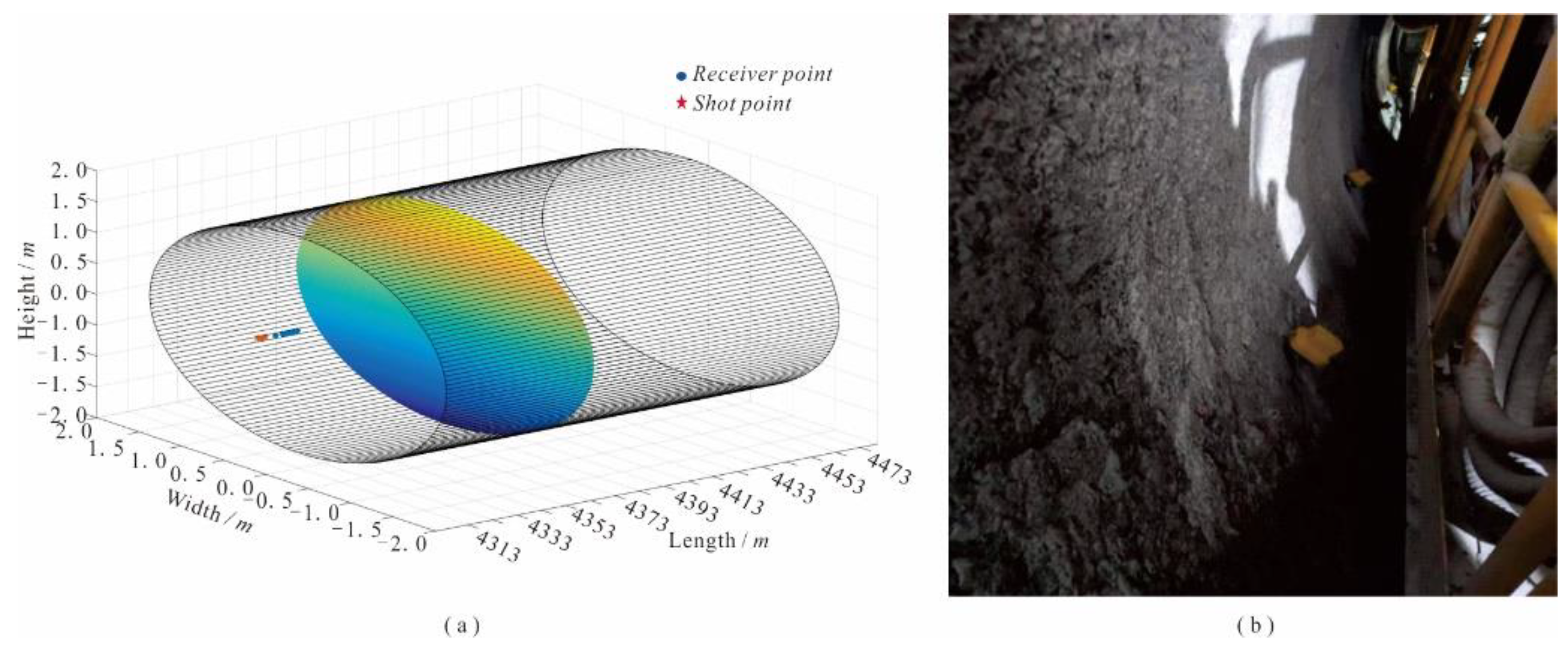
The unique construction environment of the TBM has made hammering and the use of magnetically attached triaxial seismic geophones the optimal seismic source solution. In open-type boring machines, geophones are magnetically attached to the flat trays of completed grout-filled hollow anchor rods or by using a pistol drill to create coupling bolts 8 mm in diameter and 10 cm long on the tunnel side walls, as shown in
Figure 1a. The seismic source is activated by direct hammering on the side rock walls of the tunnel. For shield-type TBMs, satisfying the conditions for drilling on tunnel side walls and direct attachment to hollow anchor rod flat trays is not feasible; instead, geophones are magnetically attached to the rivets on shield segments. Shield-type TBM segments, which bear tunnel pressure, are not conducive to direct hammering. The segments that have been grouted are fully coupled with the surrounding rock, and seismic waves generated by hammering after inserting the flat tray steel nails into the grout holes can propagate into the underground space. The overall geophone array is shown in
Figure 1(b). The schematic of the observation system is depicted in
Figure 1(c).
3. Ellipsoidal Positioning Velocity Analysis Algorithm
This paper introduces an ellipsoidal positioning velocity analysis method determined through the analysis of seismic wave polarization characteristics, three-dimensional seismic recording data, and spatial direction constraints. This method is suitable for geological advanced forecasting observation systems and does not heavily rely on the pick-up speed of the first arrival wave. It provides a more accurate and intuitive three-dimensional geological velocity model and offers parameter indices for assessing the condition of the rock ahead of the tunnel face and for evaluating rock grades, thereby providing a solid foundation for the quality of offset imaging and the reliability of forecast results.
Seismic wave velocity information is an important carrier or indicator for predicting geological hazards ahead of the tunnel. The velocity model affects not only the effects of offset imaging but also the reliability of forecast interpretation. The ellipsoidal positioning velocity analysis method, based on the characteristics of the advanced forecasting observation system and combined with the constraints of three-component data direction, determines the average ray velocity of the layers and can accurately invert the spatial velocity model.
3.1. Method Principle
The polarization characteristics of seismic waves in advanced detection reveal that seismic waves, starting from source S, reflect at reflection point P and are recorded at detection point R. This can be represented as:
where
is the trajectory of seismic wave movement,
is the velocity of the seismic wave, and
is the travel time of the seismic wave.
In three-dimensional space, the mathematical relationship is:
In the above formula,
and
are the coordinate values of source point
, detection point
and reflection point
. It is deduced that:
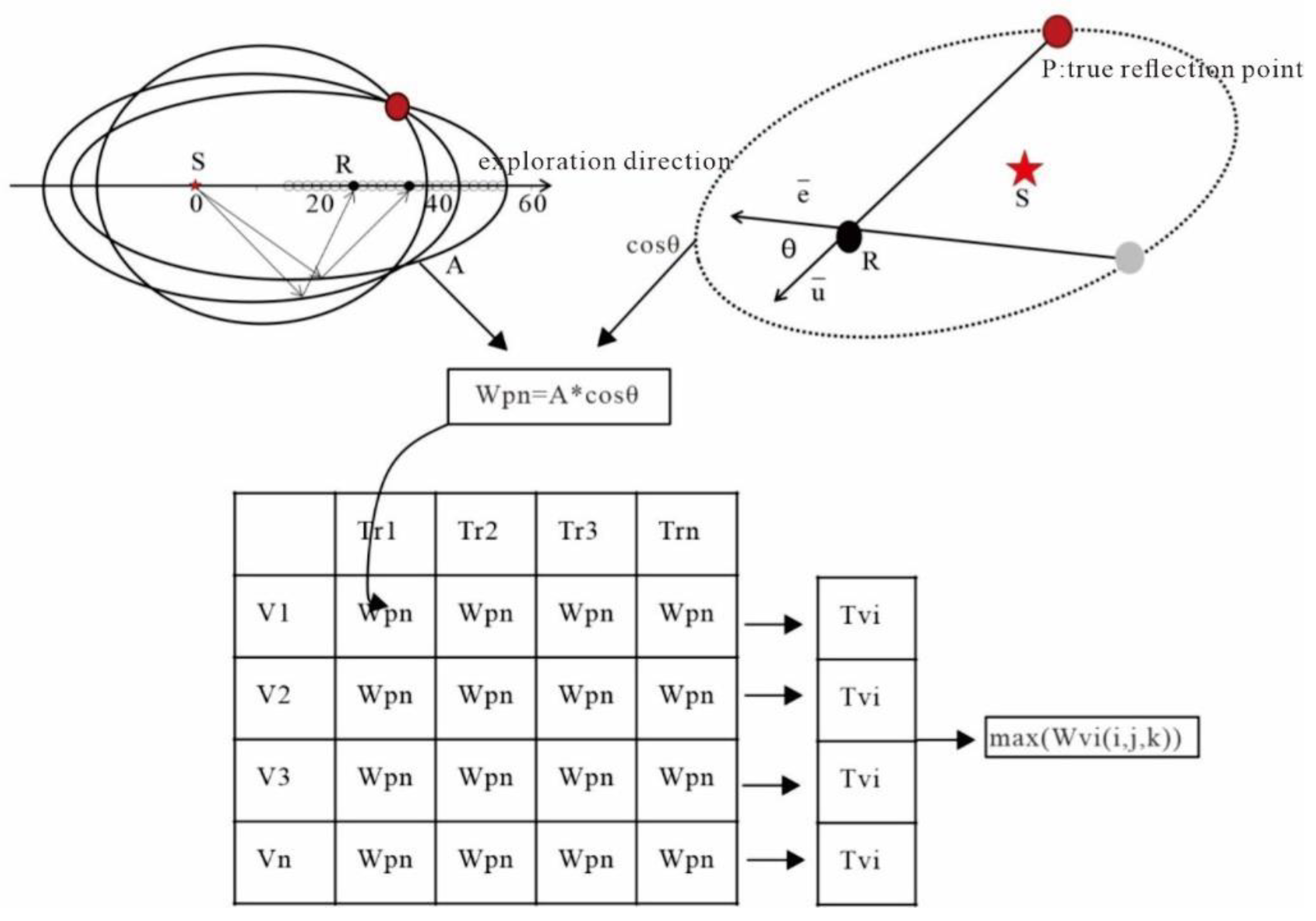
Derived from analysis, the above formula represents an ellipsoidal surface, where any point on this surface could be a reflection point. The source S and detection points R serve as the foci, with the offset as the focal length in
Figure 2.
A three-dimensional grid is created forward from the source point.
represents the grid points
.
is obtained by the reflection surface determined by the p gun and the detection point, and the restriction condition
represents amplitude. For the isochronous ellipsoid mentioned above, the value
is assigned to represent the possibility of a true reflection point:
where
is the amplitude and
is the angle between the unit vector from the point to the detection point on the isochronous ellipsoid and the vector from the real reflection point to the detection point (that is, the vector composed of the three components of the data actually recorded).
is 0 at the true reflection point, where
is equal to
and less than
everywhere else.
Then, the data space can be obtained by N gun data and vi as the speed:
When the data at the real reflection point in the data body is superimposed, its value is increased, and the value at the false anomaly is attenuated.
The 3D spatial data bodies obtained from the velocity are compared with the value of the same cell one by one, and the maximum value corresponds to the optimal velocity. The method is defined as the ellipsoidal positioning velocity analysis method.
3.2. Numerical Simulation Data Validation
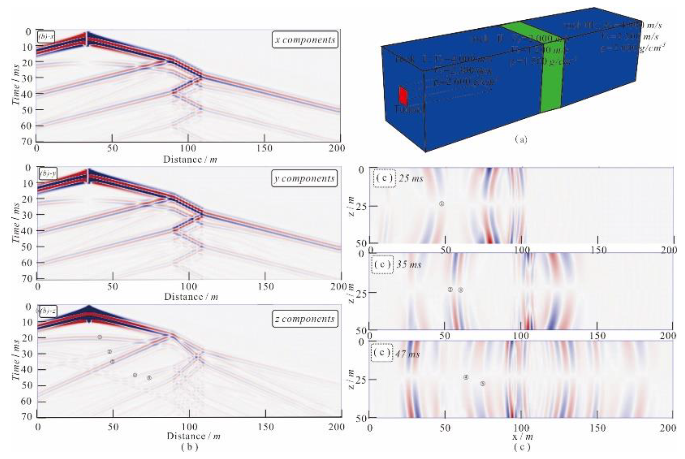
A layered tunnel geological model was established to simulate the common hazard of weak interlayered rock formations in tunnel construction, and corresponding seismic records were obtained to analyze its reliability and validate the model .
The interlayer model is shown in
Figure 3(a), with the tunnel face positioned 60 m ahead of the reference face. Surrounding rock formation one is hard rock, surrounding rock two is a weak geological body in front of the tunnel, and surrounding rock three is hard rock. Physical parameters of the rock are shown in
Table 1. The source sub-wave is a Ricker wavelet, with a sampling rate of 0.01 ms, a recording duration of 70 ms, and a seismic wave main frequency of 200 Hz. The source point coordinates (x, y, z) are (35, 30, 25), with detection points arranged along the x direction passing the source point and a track spacing of 1 m. To best mimic reality, ellipsoidal positioning velocity analysis is performed by taking 24 track data points from the source point forward along the x-axis, with P-wave velocity selection ranging from 1500 m/s to 4500 m/s and S-wave velocity selection ranging from 1000 m/s to 2500 m/s at intervals of 100 m/s.
The obtained three-component original seismic records are shown in
Figure 3(b), and its wavefield snapshot is shown in
Figure 3(c). The wavefield snapshot is oriented along the x direction, with the z-axis as the vertical axis. Through analysis, the z-component seismic records include: ① seismic waves generated at the model's starting interface, with wavefield propagation characteristics as marked in
Figure 7(a); ② and ③ direct waves and PP waves generated at the first interface of the interlayer, with wavefield propagation characteristics as marked in
Figure 3(c); and ③ and ④ transmitted P waves reflected after encountering the second interface, with wavefield propagation characteristics as marked in
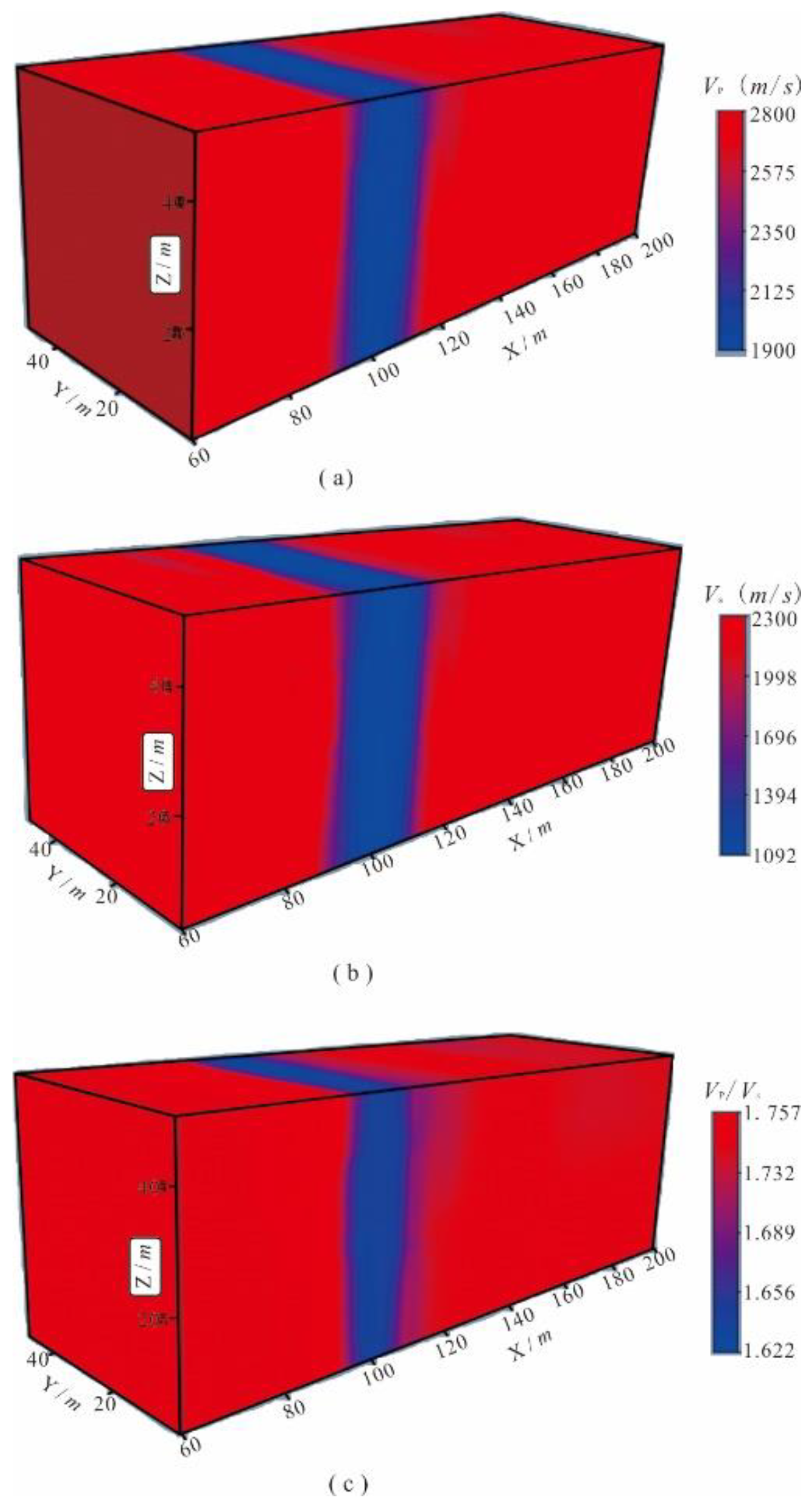
Figure 3(c). Using the ellipsoidal positioning velocity analysis method, analysis was performed on this forward seismic record. Results are shown in
Figure 4, with P-wave velocity in front of the tunnel surrounding rock at 4000 m/s, and weak surrounding rock P-wave velocity at 2000 m/s, and reflection interface at 90 m and 110 m on the x-axis. The position of the rock interface, interlayer thickness, and velocity values were precisely predicted. The velocity ratio results are shown in
Figure 4(c)and reflect changes in the water content of the surrounding rock.
4. Engineering Example
4.1. Engineering Example One—Application in TBM Construction Tunnels through Fractured Rock Zones
The tunnel is located within Tongcheng City, Anhui Province, approximately 80 km straight distance from Hefei and approximately 40 km from Anqing. The tunnel is a self-draining tunnel with a total length of 6120.8 meters. There are no major faults along the self-draining tunnel line, with joints and fractures occurring primarily at steep angles. Most of the self-draining tunnel is deeply buried in weakly weathered or slightly weathered to fresh rock, which predominantly consists of class II and III surrounding rock. In the section passing through Maojiadian No.1 Ditch, the burial depth ranges from 220 to 230 meters, while the Zhangling Ditch section ranges from 60 to 65 meters, and the Nanchong River section ranges from 45 to 50 meters. The tunnel depths are shallower in the Zhangling Ditch and Nanchong River sections, the river valleys are wider, and fractures and faults develop along the river, possibly with significant seepage. The surrounding rock is mainly class III, with fault zones classified as class IV. Approximately 180 meters south of the Nanchong River, the tunnel section intersects almost perpendicularly with the F1 fault, which has an orientation of N50° to 70 °E/NW (SE) at an angle of 75° to 85°, a width of 4 to 7 meters, and a distorted fault surface. This is at the contact line between the Liu Fan Group diorite and the Bengbu period mixed granite, with the fault zone commonly seeing late Yanshan period diorite intrusions, consisting of fractured rock, structural breccia, and compressed schist, primarily in a weakly weathered state, with some areas showing strong weathering. The surrounding rock is fractured and classified as class IV.
4.2. Data Collection
Source location: 4 excitation points are arranged on the side wall behind the receiving point, spaced 1 meter apart, with each point activated three times for signal stacking to ensure effective seismic wave excitation in the surrounding rock. Receiver location: Six triaxial geophones are placed between the source and the cutter head to receive full-space vibration signals, with a track spacing of 1.5 meters, a minimum offset distance of 4 meters, and a maximum offset distance of 16 meters. Geophones are applied in a triaxial flush-wall manner, with the x-direction as the advancing direction, the y-direction perpendicular to the tunnel wall, and the z-direction perpendicular to the horizontal plane. The tunnel face mileage is ZLD4+373, advancing from the smaller to the larger mileage. The tunnel face is circular, with the top of the face at 0 degrees, the bottom at 180 degrees, and the angles increasing clockwise. In the two-dimensional plane, the center is at point (0, 0), with a diameter of 3.5 meters. The hammer point record table is shown in
Table 2, the wave point record table is shown in
Table 3, and the measurement system schematic is shown in
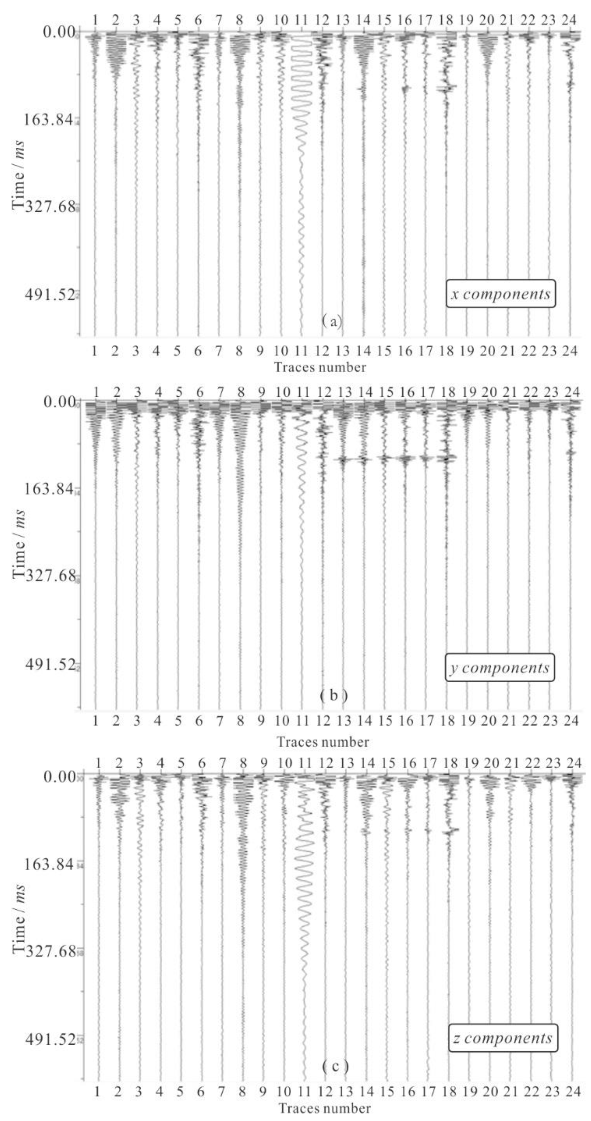
Figure 5. The original seismic records are shown in
Figure 6.
The collected original records contain 24 tracks of three-component seismic data, where tracks 1-6 were generated by the first hammer point, 7-12 by the second hammer point, 13-18 by the third hammer point, and 19-24 by the fourth hammer point.
4.3. Data Processing
The raw data undergo several processing steps, including data preparation, bad track removal, band-pass filtering and time-variant filtering, first-arrival picking, shot energy balancing, Q factor estimation compensation, reflection wave extraction, P-wave and S-wave separation, velocity analysis, depth migration, and reflection layer extraction. These processes ultimately yield the physical parameters of the geological bodies in front of the tunnel and the positions of the reflection interfaces.
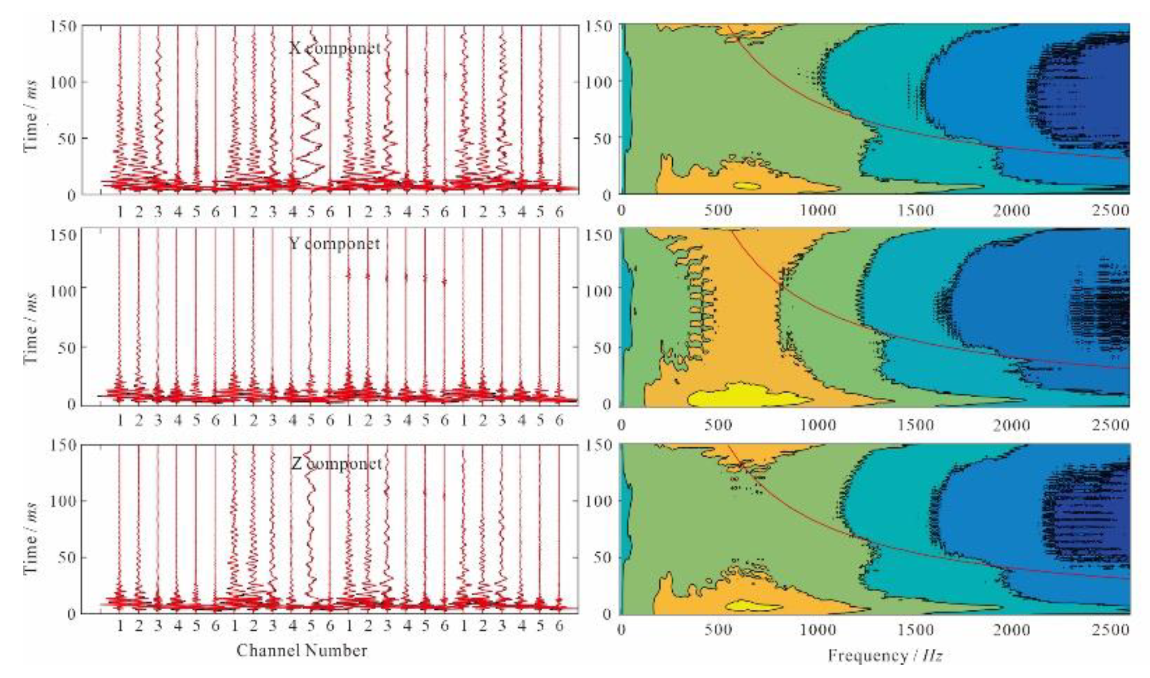
The original seismic record spectrum has an effective frequency range of 10-2000 Hz, with a dominant frequency of 800 Hz. Time-frequency filtering is illustrated in
Figure 7, where the red waveform on the left represents the result after filtering, and the black waveform represents the seismic record after band-pass filtering. The red line on the right side of the figure demarcates the energy retained on the left and the energy filtered out on the right. The analysis results for the P-wave velocity are shown in
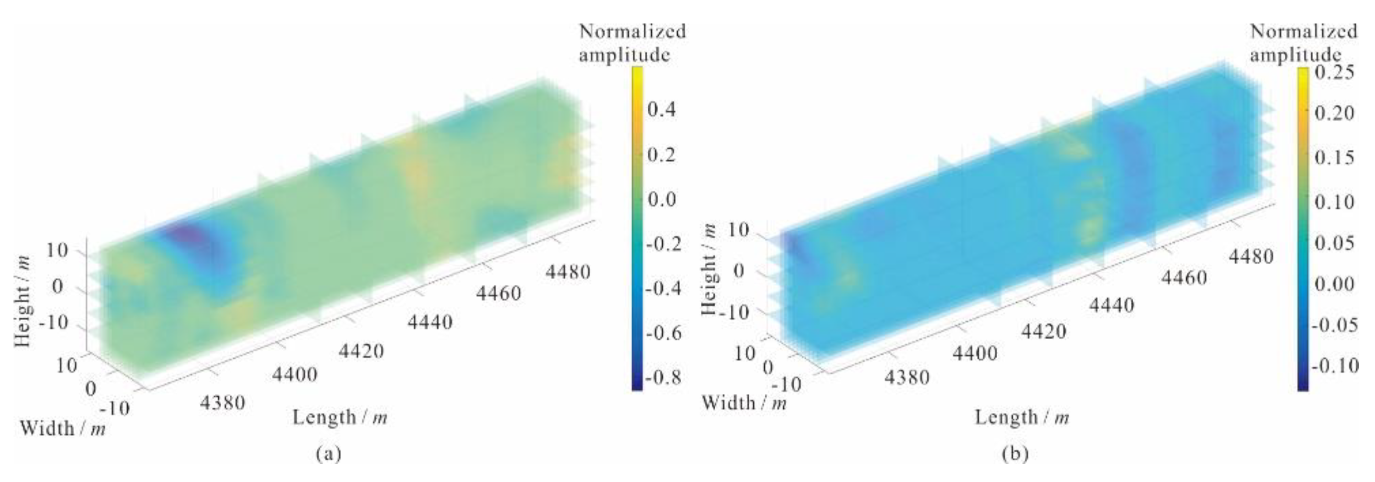
Figure 8(a), and the S-wave velocity analysis results are displayed in
Figure 8(b). The results for P-wave offset are shown in
Figure 9(a), and the results for S-wave offset are depicted in
Figure 9(b).
Figure 7.
Time frequency analysis waveform data and time-frequency spectrum.
Figure 7.
Time frequency analysis waveform data and time-frequency spectrum.
4.4. Data Interpretation
This forecast covers the mileage from 4373 to 4493, where the surrounding rock primarily consists of diorite, and the construction is designated as class III.
Combining engineering surveys and borehole revelations from the excavation, the area exhibits uneven weathering, faults, and jointing. The anomalous reflection positions correlate with the degree of weathering and the fractured zones of the surrounding rock, with specific forecast results shown in
Table 3.
Table 3.
Table of results of advanced geological prediction.
Table 3.
Table of results of advanced geological prediction.
| Serial number |
Forecast range |
|
Length (m) |
Forecast mileage surrounding rock conditions |
Forecast range reference grade of surrounding rock |
| 1 |
4373~4413 |
|
40 |
The average longitudinal wave velocity in this section is 3750 ~ 4150 m/s, and the wave velocity is distributed from height to bottom, and decreases significantly after 4400, and the average transverse longitudinal wave velocity is 2068 ~ 2689 m/s. There are many strong reflection positions, medium weathering, and the integrity of surrounding rock is general. |
Level III |
| 2 |
4413~4460 |
|
47 |
The longitudinal wave in this section is low, and the average longitudinal wave velocity is 3550 ~ 3700 m/s. The shear wave velocity in this section is increased, and the average shear wave velocity is 2081 ~ 2737 m/s. The wave velocity ratio increases significantly after 4420, and the possibility of water in this section is higher than that in the previous section. Surrounding rock integrity is poor, broken, water. |
Level IV |
| 3 |
4460~4493 |
|
33 |
The longitudinal wave velocity in this section is increased, the average longitudinal wave velocity is 3750 ~ 4250 m/s, the shear wave in this section is stable, the wave velocity ratio is increased, the strong reflection position is more, the surrounding rock is moderately weathered, the integrity is general, and the water is contained. |
Level III |
4.5. Field Verification
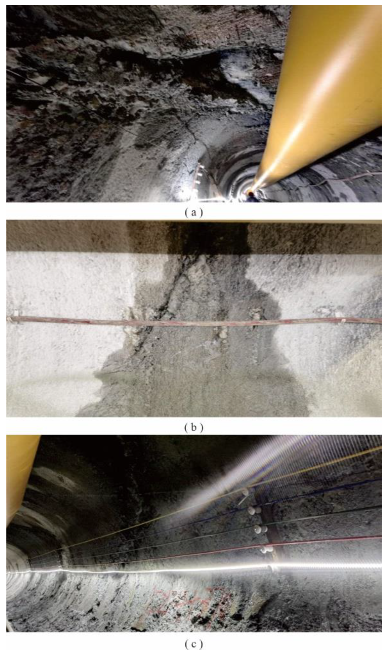
After the TBM excavation, field results confirmed the accuracy and reliability of our findings.
Figure 10(a) shows that the surrounding rock at the top of the tunnel is noticeably fractured with falling blocks; Figures 10(a) and 10(b) indicate the presence of fissure water in the tunnel; Figures 10(b) and 10(c) demonstrate that the integrity of the tunnel's surrounding rock is poor, with evidence of significant cracking.
5. Conclusions
This paper focused on the application of advanced geological forecasting for TBM construction methods based on ellipsoidal positioning velocity analysis. The layout of an observation system suitable for advanced forecasting in TBM construction tunnels was developed along with key technologies for data processing based on an ellipsoidal positioning velocity analysis, including a simulation of three-dimensional seismic waves for advanced forecasting. The method has achieved good results in practical engineering applications. The main conclusions are as follows:
A linear observation system was developed based on the spatial feasibility of advanced geological forecasting within TBM tunnels, the characteristics of the observation system setup, general regulations, signal collection requirements, data analysis and interpretation requirements, and the standards for classifying surrounding rock. A method for installing geophones in different types of tunnels was proposed. Numerical simulations of seismic waves demonstrated that this approach could acquire seismic information ahead of the tunnel face, thus maximizing the limited observation space available and proving suitable for TBM construction tunnels.
For TBM tunnel advanced geological forecasting, a data processing workflow based on ellipsoidal positioning velocity analysis was established. This workflow effectively processes the collected triaxial seismic data, including three-dimensional velocity bodies, three-dimensional velocity ratios, and three-dimensional offset imaging results, by extracting information about geological bodies approximately one hundred meters ahead of the tunnel face. Considering the small amount of seismic signal data and the high requirements for interpretation precision, the ellipsoidal positioning velocity analysis method was proposed. Based on the characteristics of the advanced forecasting observation system and combining the constraints of the three-component data direction, it accurately inverts the spatial velocity model.
In this study, a TBM advanced geological forecasting system based on ellipsoidal positioning velocity analysis was developed and validated for TBM tunnels. The practical application in engineering verified the design of the observation system, the settings of the data processing workflow, and the reasonableness and accuracy of the data interpretation. According to the geological data obtained after TBM advancement, the results indicated that this method could be effectively applied to the advanced forecasting of TBM tunnels, accurately predict the fractured zones ahead of the TBM cutterhead in Engineering Example One, and accurately forecast the hazards of weak interlayers in Engineering Example Two. Results confirmed the practicality and reliability of the advanced geological forecasting application based on ellipsoidal positioning velocity analysis.
Author Contributions
Conceptualization, Z.G. and W.W.; methodology, W.W.; software, W.W.; validation,W.W., B.H. and X.R.; formal analysis, Z.G,W.W. and J. L.; investigation, Z.G., X.R. J. L and B.H.;Writing—original draft preparation, Z.G. and W.W.; Writing—review and editing, Y.W.; Funding acquisition,W.W. All authors have read and agreed to the published version of the manuscript..
Funding
This work was supported in part by the Science and Technology Plan Project of Linzhi, Xizang under Grant SYQ2024-12. This research is supported by the project of ‘Research on Three dimensional Advanced Geological Prediction Technology for Shield Tunnel Induced Polarization Dipole’and NSFC (grant no. 41641040).
Data Availability Statement
Data supporting the reported results can be found in the literature cited in the manuscript.
Conflicts of Interest
The authors declare no conflict of interest.
References
- Zhao, Y.; Tian, S. M. Sun Yi. The Development and Planning of High-Speed Railway Tunnels in China. Tunnel Construction 2017, 37, 11.
- Zhao, Y. G. Review and Recommendation of Domestic and International Tunnel Advanced Forecasting Technologies. Progress in Geophysics 2007, 1344–1352. [Google Scholar]
- Ma, J.; Sun, S. Z.; Zhao, W. Y.; et al. A Review of Academic Research on Tunnel Engineering in China 2015. China Highway 2015, 28, 1–65. [Google Scholar]
- Wang, M. S.; Tan, Z. S. Chinese Tunnel and Underground Engineering Construction Technology. Chinese Engineering Science 2010, 12, 4–10. [Google Scholar]
- Jing, L. J.; Zhang, N.; Yang, C. Development and Trends of TSP and Its Construction Technology in China. Tunnel Construction 2016, 36, 331–337. [Google Scholar]
- Liu, Z. G.; Liu, X. F. Application and Development of TSP (Tunnel Seismic Prospecting) in Advanced Forecasting of Tunnel Excavations. Rock Mechanics and Engineering 2003, 22, 1399–1402. [Google Scholar]
- Liu, D. P. Discussion on the Construction Plan of TBM in Fault Karst and Other Adverse Geological Sections. Science and Technology Innovation Herald 2017, 14, 2. [Google Scholar]
- Chen, H. Research on the Correlation between TBM Excavation Efficiency and Surrounding Rock. Chengdu: Southwest Jiaotong University, 2010.
- Liu, B.; Nie, C. C.; Li, S. C.; et al. Numerical Simulation and Experimental Study on Real-time Monitoring of Tunnel Water Inrush Disaster by Electrical Resistivity Tomography Method. Chinese Journal of Geotechnical Engineering 2012, 34, 2026–2035. [Google Scholar]
- Li, S. C.; Xue, Y. G.; Zhang, Q. S.; et al. Research on Key Technologies for Comprehensive Forecast and Early Warning of Geological Disasters in Tunnel Construction in High-Risk Karst Regions. Chinese Journal of Rock Mechanics and Engineering 2008, 27, 1297–1307. [Google Scholar]
- Li, L. P. Study on catastrophe evolution mechanism of karst water inrush and its engineering application of high risk karst tunnel. NanJing: Shandong University, 2009.
- Li, B. Experimental Study on Downhole Seismic Method in Mines. Xuzhou: China University of Mining and Technology, 2015.
- Xiang, H. Evaluating the Excavability of TBM Tunneling in Composite Strata. Chongqing: Chongqing University, 2016.
- Cheng, J. L.; Xie, C.; Sun, X.Y.; et al. Preliminary Exploration of the Theory and Method of Seismic Prospecting Ahead of Tunneling. 2015 Chinese Earth Sciences Joint Academic Annual Meeting, 2015, 1765-1766.
- Chen, L. Imaging Method and Application of TBM Rock Breaking Seismic Wave Prospecting Ahead Based on A Priori Constraints. Jinan: Shandong University, 2020.
- Richard O,; Edward B. ; Helfried, B.; Peter, S. The Application of TRT-Ture Reflection Tomo-graphy-at the Unterwald Tunnel. Geophysics, 2002, 2, 51~56.
- Cai, J. H. Wang, Y. G. Zhang, G. B. Advanced geological forecasting of landslide at tunnel body during construction. Journal of Engineering Geology 2015, 23, 778–783. [Google Scholar]
- Lu, J. W.; Chen, Z. Hu, J. et al. The application of multi - electrode resistivity method in tunnel geological prediction. Journal of Engineering Geology 2016, 24, 1417–1421. [Google Scholar]
- Gao, Z. Z. The application of the Beam geological advance prediction system for the TBM construction of Jinping diversion tunnel. Railway Construction Technology 2009, 65-67.
- Zhang, M. G. Wang Miaoyue. Anisotropic Elastic Wave Finite Element Pre-stack Reverse Time Migration. Chinese Journal of Geophysics 2001, 44, 711–719. [Google Scholar]
- Du, Q. Z.; Qin Tong. Multi-component Pre-stack Reverse Time Migration of Elastic Waves in Transversely Isotropic Media. Chinese Journal of Geophysics 2009, 52, 801–807. [Google Scholar]
- Ding, R. W.; Li, Z. C.; Sun, X. D.; et al. Imaging Conditions for the Initiation Time in Pre-stack Reverse Time Depth Migration. Progress in Geophysics 2008, 209–215. [Google Scholar]
- Zhang, Z.; Liu, Y. S.; Xu, T.; et al. Stable Excited Amplitude Imaging Conditions in Elastic Wave Reverse Time Migration. Chinese Journal of Geophysics 2013, 56, 3523–3533. [Google Scholar]
- McMechan, G. A. Migration by extrapolation of time-dependent boundary values. Geophysical prospecting 1983, 31, 413–420. [Google Scholar] [CrossRef]
- Mulder, W. A.; Plessix, R. E. A comparison between one-way and two-way wave-equation migration. Geophysics 2004, 69, 1491–1504. [Google Scholar] [CrossRef]
- Ashida, Y. Seismic imaging ahead of a tunnel face with three-component geophones." International journal of rock mechanics and mining sciences. 2001, 38, 823~831.
- Gray, S. H.; Etgen, J.; Dellinger, J.; et al. Seismic migration problems and solutions. Geophysics 2001, 66, 1622–1640. [Google Scholar] [CrossRef]
- Yuzuru, A.; Koichi, S. Depth Transform of Seismic Data by Use of Equi-Travel Time Planes. Exploration Geophysics 1993, 24, 341–346. [Google Scholar]
- Lu, B.; Cheng, J. Y.; Hu, J. W.; Qin, S. Seismic Features of Vibration Induced by Mining Machines and Feasibility to be Seismic Sources. Procedia Earth and Planetary Science 2011, 76–85. [Google Scholar] [CrossRef]
- Liu, B.; Chen, L.; Li, S. C.; Xu, X. J.; Liu, L. B.; Song, J.; Li, M. A new 3D observation system designed for a seismic ahead prospecting method in tunneling. Bulletin of engineering geology and the environment 2018, 77, 1547–1565. [Google Scholar] [CrossRef]
- Bellino, A.; Garibaldi, L.; Godio, A. An automatic method for data processing of seismic data in tunneling. Journal of Applied Geophysics 2013, 98, 243–253. [Google Scholar] [CrossRef]
- Swinnen, G.; Thorbecke, J. W.; Drijkoningen, G. G. Seismic Imaging from a TBM. Rock Mechanics and Rock Engineering 2007, 40, 577–590. [Google Scholar] [CrossRef]
- Masaru, K.; Takeshi, I. Prediction of seismic loadings on wind turbine support structures by response s pectrum method considering equivalent modal damping of support structures and reliability level. Wind Energy 2020, 23, 1422–1443. [Google Scholar]
|
Disclaimer/Publisher’s Note: The statements, opinions and data contained in all publications are solely those of the individual author(s) and contributor(s) and not of MDPI and/or the editor(s). MDPI and/or the editor(s) disclaim responsibility for any injury to people or property resulting from any ideas, methods, instructions or products referred to in the content. |
© 2024 by the authors. Licensee MDPI, Basel, Switzerland. This article is an open access article distributed under the terms and conditions of the Creative Commons Attribution (CC BY) license (http://creativecommons.org/licenses/by/4.0/).
