1. Introduction
Magnetism is the fundamental principle behind the working of an electromagnetic engine. The forces of attraction and repulsion produced on the electromagnet, when current is passed through it, are converted into mechanical work. Electromagnetic engines can be designed and powered in a variety of ways. A design has been developed wherein an engine functions akin to a piston engine, featuring an electromagnet affixed to the cylinder head and a permanent magnet attached to the piston head. Upon applying current to the electromagnet, the permanent magnet experiences attraction or repulsion, inducing movement of the piston in an upward and downward motion, consequently driving the rotation of the crankshaft [2]. A similar design has been described wherein the battery source of appropriate voltage energizes the electromagnet positioned on the cylinder head. The utilization of a cyclo converter, a device that alters the frequency of the supplied A.C. current to the necessary frequency for engine operation, has been emphasized. This converter facilitates the continuous attraction and repulsion of magnets by altering their polarity. One notable advantage of electromagnetic engines is their efficiency. By not depending on combustion, they generate zero emissions and achieve a superior energy conversion rate, rendering them a sustainable alternative to conventional combustion engines [3]. Additionally, electromagnetic engines can operate quietly and with less vibration, making them suitable for a wide range of applications.
Despite their potential advantages, there are still challenges to overcome in the development and implementation of electromagnetic engines. These include the cost of materials and manufacturing, as well as the need for a reliable power source. The electromagnetic engine designed by the authors not only has advantages but also works on overcoming the challenge of reliable power sources. It works using the Arduino to enhance the performance and ease the controlling of the conventional Adams pulse motor.
The original invention of Robert Adams was an electric motor that comprised a rotor consisting of radially arrayed permanent magnet poles and a stator consisting of permanent magnet cores as well as several electromagnetic wound poles in which electric energy is fed. Various modifications have been made to this invention. A motor design has been proposed where the stator incorporates D.C. electromagnets and the rotor features permanent magnets securely affixed to it [5]. The original invention has been modified by utilizing rectangular soft magnetic cores in place of the C-shaped cores. The corona discharge, on which the corona motor works, is a plasma that is formed on sharp edges, needles, thin wires, or points where the electric field generated is large [6]. It has been mentioned that the fundamental structure of the corona motor involves a rotor, either disc-shaped or cylindrical, encircled by numerous sharp-edged stator electrode [7]. It has been noted that the disc is composed of insulating material, with the electrodes being alternately connected to the positive and negative terminals of a high-voltage D.C. source [12]. A corona discharge-based electrostatic motor has been fabricated, featuring a cylindrical rotor crafted from aluminum foil and stator electrodes composed of copper, insulated by a cylindrical wooden shell [12]. Another optimization involved the motor electrodes discharging charge towards the insulator-made rotor, leading to repulsion between the stator electrodes and the accumulated charge on the rotor, resulting in the rotation of the disc [9]. This condition is explained as the ‘Coulomb repulsion’ between the rotor and the stator, which levitates the rotor [11]. It is mentioned that the driving force of an electrostatic motor is small, leading to limitations in its applications [10].
Furthermore, in response to the challenges associated with the exclusive use of electromagnetic engines, an inventive approach has been devised. This involves the seamless integration of an Arduino microcontroller into an established design of the Adams Pulsed Motor. This integration is complemented by an extensive optimization process aimed at improving the motor’s performance metrics and simplifying its operational procedures. Through these enhancements, the novel system promises to offer superior functionality and user-friendliness compared to conventional electromagnetic engines.

3. Design of Adam’s Pulsed Motor
The fabrication of Adam’s pulsed motor had the following major steps- Finding suitable components (magnets, ball bearings, copper wire, core, and shaft), Drive winding on iron core, and Assembly. The basis of the selection of materials for this motor was compatibility with other components and expected output. All the materials used in this motor are listed in
Table 1. The materials proposed for the conceptual design of the Adams pulse motor are carefully selected to ensure the feasibility and effectiveness of the motor’s operation. Each material serves a distinct purpose within the motor system, contributing to its overall functionality and reliability.
The stator comprises a soft iron core with copper drive windings. Soft iron is chosen for its high magnetic permeability, facilitating efficient electromagnetism generation. Copper drive windings offer low electrical resistance and high conductivity, ensuring effective energy transfer into magnetic fields. The rotor consists of permanent ferrite magnets arranged in a “plus” configuration. Ferrite magnets are selected for their strong magnetic fields and long-term stability, ensuring consistent motor performance over time. Stainless steel ball bearings are chosen for their corrosion resistance and durability. The 10mm size matches the diameter of the shaft, providing smooth and reliable rotation of motor components. The shaft is made of chrome-plated stainless steel to provide corrosion resistance and hardness.
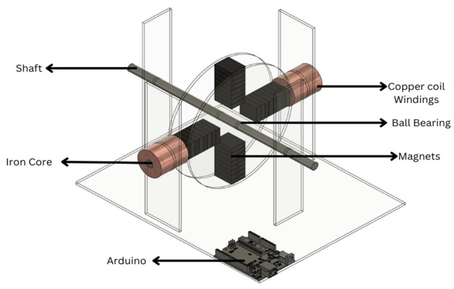
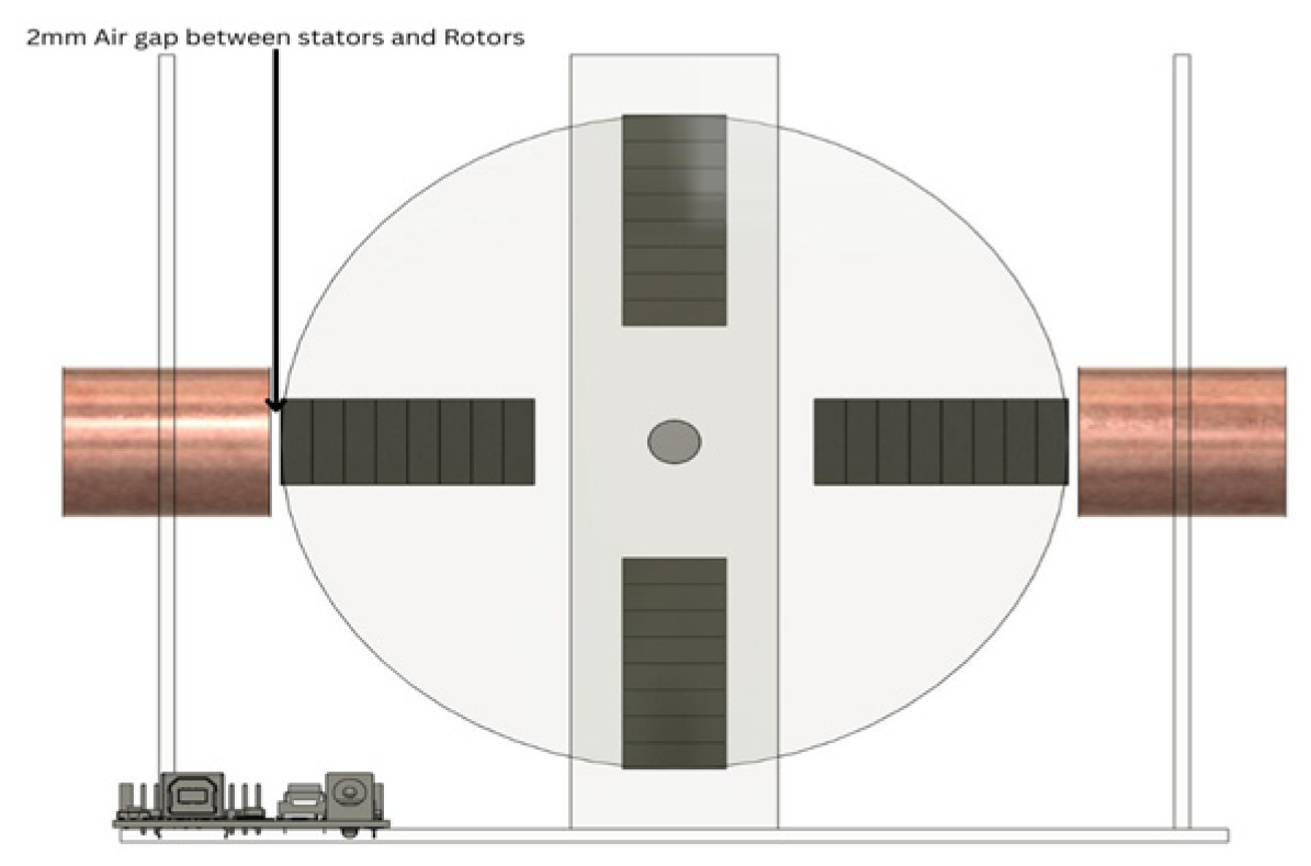
The 10mm diameter shaft offers sufficient strength and durability to withstand rotational forces during motor operation. Acrylic sheets are selected for support due to their transparency, lightweight, and ease of fabrication. The 3mm thickness provides adequate support for motor components while maintaining the visibility of internal mechanisms. The casing is proposed to be made of acrylic discs with a diameter of 152mm and a thickness of 6mm. Acrylic discs offer structural support and protection for the rotor and magnets, while maintaining visibility of internal components for inspection and maintenance purposes. This motor has 2 iron cores with copper drive windings used as stators. The length of the iron core used is approximately 40 mm and the diameter of approximately 10 mm. The stators are held in place using 3 mm acrylic discs. The rotor casing is made up of two acrylic discs with a diameter of 152 mm and a thickness of 6 mm each. The casing encloses 32 ferrite magnets in a “+” configuration. Each arm has 8 magnets stuck together and they are placed such that there is similar polarity on the outer side of the rotor throughout. The 10 mm chrome-plated stainless-steel shaft is held by two 3 mm acrylic sheet supports and it rotates with the help of 10 mm stainless steel ball bearings. The bearings, supports, and magnets are fixed using a suitable adhesive.
Figure 1 properly illustrates the configuration of materials in Adam’s Pulsed motor.
Figure 1.
Isometric View of the 3D Design.
Figure 1.
Isometric View of the 3D Design.
Figure 2.
Front view of Adams Pulse Motor Showing 2mm gap.
Figure 2.
Front view of Adams Pulse Motor Showing 2mm gap.
4. Circuit Design and Connections
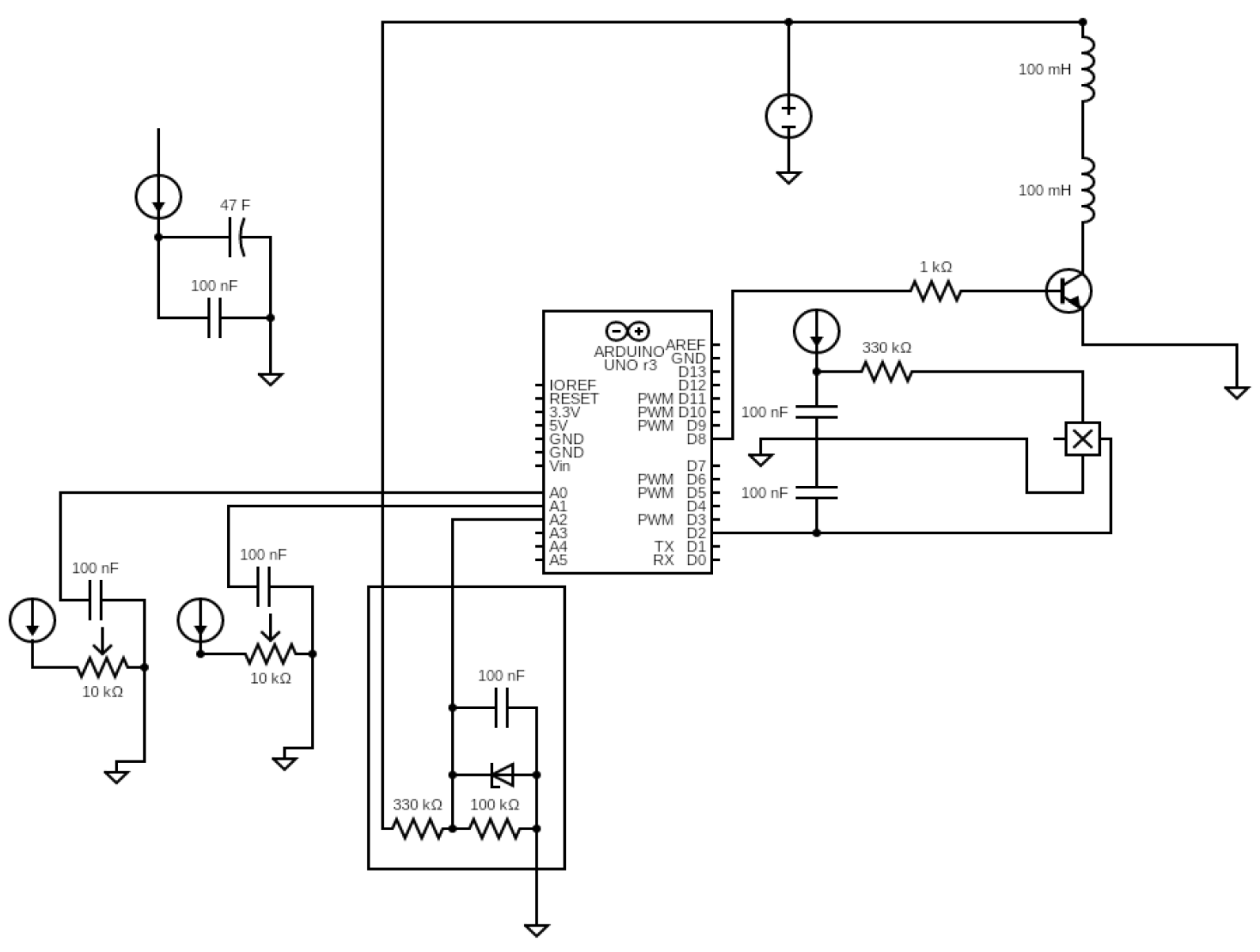
The described circuit integrates an Arduino UNO microcontroller as the main central system for controlling and monitoring the performance of an Adam’s Pulsed motor. This motor is designed to operate in a pulsed manner, possibly for applications where precise control over speed and torque is essential. The Arduino’s programmed algorithms generate timed electrical pulses to drive the motor, with parameters such as duty cycle and pulse timing being adjustable via potentiometers. This flexibility allows users to fine-tune the motor’s behavior according to specific requirements.
Critical to the operation is the Hall effect sensor, which detects the magnetic field generated by the motor. This sensor feeds back information to the Arduino, enabling it to regulate the current supplied to the motor’s stator drive winding. By adjusting the current based on real-time magnetic field measurements, the Arduino optimizes the motor’s performance, ensuring efficient operation while minimizing energy consumption and heat generation.
The inclusion of a flyback EMF protection circuit underscores the circuit’s robustness and reliability. This circuit mitigates the risk of voltage spikes that can occur when the motor’s magnetic field collapses, safeguarding the sensitive electronic components from potential damage. Overall, this integrated system represents a sophisticated approach to motor control, offering precise adjustments, real-time monitoring, and protective features to ensure consistent and efficient operation of the Adam’s Pulsed motor in various applications.
Figure 3.
Arduino Controlled Circuit.
Figure 3.
Arduino Controlled Circuit.
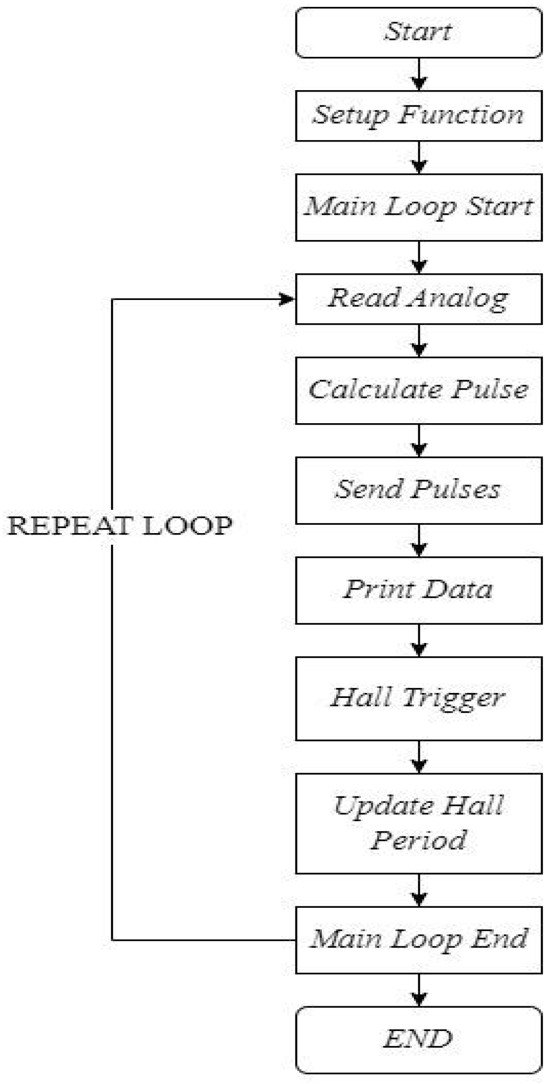
Figure 4.
Flow chart of the algorithm for Arduino.
Figure 4.
Flow chart of the algorithm for Arduino.
6. Working
The Adams pulsed motor operates on the principles of electromagnetism and utilizes pulsating electrical currents to induce rotational motion. This motor consists of a stator and a rotor configuration, each playing a crucial role in its operation. The stator of the Adams pulsed motor typically comprises a soft iron core wound with copper wire coils, known as drive windings. When an electric current flows through these coils, it generates a magnetic field around the stator. The soft iron core enhances the magnetic permeability, allowing for efficient concentration and propagation of magnetic flux. The configuration of the drive windings influences the strength and direction of the magnetic field produced, determining the motor’s torque and rotational direction. The rotor of the Adams pulsed motor consists of permanent magnets, usually made of ferrite material, arranged in a specific configuration. These magnets are affixed to a rotor assembly, which is positioned within the magnetic field generated by the stator. The arrangement of magnets on the rotor, often in a radial or axial pattern, interacts with the magnetic field produced by the stator when electrical pulses are applied.
At rest, the rotor is aligned in a specific orientation relative to the stator’s magnetic field. The magnetic poles of the rotor magnets are positioned such that they interact with the magnetic poles of the stator in a manner that minimizes resistance to rotation. Electrical pulses are applied to the drive windings of the stator, causing fluctuations in the magnetic field strength. These pulses may be generated by an external control system, such as an Arduino microcontroller, to regulate the motor’s speed, torque, and direction. As the magnetic field of the stator fluctuates, it induces corresponding changes in the magnetic field surrounding the rotor. This interaction between the stator’s magnetic field and the rotor’s permanent magnets creates a repulsive or attractive force, depending on the relative alignment of magnetic poles. The repulsive or attractive forces exerted between the stator and rotor magnets result in the rotational motion of the rotor. This motion continues as long as the electrical pulses are applied to the stator, driving the rotor in a continuous cycle of rotation. In advanced designs, feedback mechanisms may be incorporated to monitor and adjust the motor’s performance in real time. These mechanisms can include sensors for measuring speed, torque, and position, allowing for precise control and optimization of motor operation.
7. Power Calculations
-
The Stator
For the stator coil/drive windings,
Wire diameter: 0.32 mm or 28 AWG
Bobbin Diameter = 15 mm
Bobbin length = 38 mm
Number of turns = 2540
Wire length = 170 m
Cross-sectional Area = 176.7 mm2
The resistance of one stator coil is calculated by:
[ρ = resistivity of copper wire at 20 ˚C = 1.68 x 10⁻⁸]
- 2.
The rotor:
A constant DC power supply has been provided and the time path of the voltage and its corresponding current is measured on just one of the drive windings. The magnitude of the constant supply voltage is 35 V. The values and the calculations are purely based on ideal conditions. No losses (both eddy currents and hysteresis) were considered. The average resistance of the drive windings connected in series for the drive windings is 35.9 Ω. A Mechanical Load corresponding to the value of M= 0.35Nm is added at one end of the shaft.
- o
B is the magnetic flux density in Tesla (T).
- o
μo is the permeability of free space (4π ×Tm/A).
- o
M is the magnetization of the magnet in Amperes per meter (A/m).
- o
a, b, and c are the dimensions of the magnet (length, width, and thickness respectively) in meters (m) i.e., here a = 0.025 m, b = 0.02 m, c = 0.006 m
- o
d is the distance from the magnet surface at which the magnetic field strength is being, (0m )
The magnetic flux density of a single magnet comes out be,
As per the calculations derived in the Arduino Uno R3 from the corresponding codes, for a duty cycle of 14.56%, we obtain 500 RPM. So, considering 500 RPM as the angular rotations for the resultant output ) i.e.,
The torque produced multiplied by the speed of the circular orbit gives the motor’s efficiency.
The overall Efficiency percentage of the motor is the ratio of output power to Input power . The implemented machine’s final efficiency, with the ideal timing for switching current into coils, the duty cycles of the circuit after entering the necessary values,
8. Result and Discussion
Adam’s Pulsed Motor is a revolutionary innovation poised to address critical industry challenges such as frictional losses, fossil fuel dependency, and financial constraints. With an impressive efficiency of up to 54.24%, this sustainable machine operates without any fuel usage, aligning perfectly with the goal of a greener environment. It not only delivers torque but also generates flyback EMF, which, when scaled up, could power various electrical circuits in aircraft and automobiles. One notable advantage of Adam’s motor is its ability to provide torque without the need for fossil fuels, making it an ideal candidate for aircraft applications where minimizing emissions is crucial. Moreover, its integration with advanced control systems like Arduino opens up possibilities for precise control and optimization in aircraft propulsion systems. Despite its initial limitation of self-starting, innovative solutions have been devised to overcome this hurdle. The incorporation of a simple BLDC motor into the powertrain ensures sufficient torque, making Adam’s motor an attractive option for aircraft propulsion systems. In the context of aviation, the potential of Adam’s motor extends beyond just torque delivery. Its ability to generate flyback EMF opens avenues for powering onboard electrical systems, contributing to the efficiency and sustainability of aircraft operations.
9. Conclusions
In conclusion, the conceptual design of an Arduino-controlled Adams pulsed motor offers a promising solution to the pressing challenges of greenhouse gas emissions and limited fuel resources in the aerospace industry. Despite being in the theoretical stage without a physical prototype, the potential impact of such an engine is substantial. By leveraging the precise control capabilities of Arduino microcontrollers, this design aims to enhance efficiency and sustainability in aerospace propulsion systems. Beyond traditional propulsion, the versatility of Arduino-controlled pulsed motors extends to various aircraft subsystems, including flight control systems, power generation, and payload deployment in UAVs and satellites. Further research and development in this field hold the key to unlocking the full potential of these innovative technologies and accelerating the transition to a greener future for aerospace engineering.
References
- Eason, George, Benjamin Noble, and Ian Naismith Sneddon. “On certain integrals of Lipschitz-Hankel type involving products of Bessel functions.” Philosophical Transactions of the Royal Society of London. Series A, Mathematical and Physical Sciences 247.935 (1955): 529-551.
- Eapen, Abil Joseph, et al. “Electromagnetic engine.” International journal of research in engineering and technology3.06 (2014): 2319-1163.
- Duvvuri, Anirudh Satya, and N. Venkatachalapathi. “Viabilities of Replacing Combustion Engine by Electromagnetic Engine.” Innovative Design and Development Practices in Aerospace and Automotive Engineering: I-DAD, February 22-24, 2016. Springer Singapore, 2017.
- “The Adams Pulsed Motor Generator Manual,” Google Book (Adams,1993)n.d. Available online: https://books.google.co.in/books?id=SDDctgAACAAJ.
- Krishnan, Ramya Santhana Gopala et al. “ Permanent magnet pulse motor-generator to generate electric power and charge the batteries with free energy charging systems ” PROJECT REFERENCE NO.: 37 S 1106.” (2014).
- Koutny, Martin and Petr Kačor. “Completion and operational testing of the Adams’ permanent magnet electric D.C. motor-generator.” 2015 16th International Scientific Conference on Electric Power Engineering (EPE) (2015): 560-565.
- Leng, Jiaming, Zhiwei Liu, Xiaoyong Zhang, Dawei Huang, Mingjing Qi, and Xiaojun Yan. “Design and analysis of a corona motor with a novel multi-stage structure.” Journal of Electrostatics 109 (2021): 103538.
- Abdel-Salam, M., A. Ahmed, H. Ziedan, and F. Diab. “Analysis of a Corona-Discharge Based Electrostatic Motor.” Electrical Engineering Department, Assiut University (2014).
- Krein, Philip T. “Analysis of corona motors and micromotors by means of effective gap conductivity.” IEEE transactions on industry applications 31, no. 4 (1995): 752-760.
- Feng, Haozhe. “Research status and development trends of Electrostatic Motor.” Highlights in Science, Engineering and Technology 16 (2022): 338-343.
- Rambin, Christopher Lee. The optimized electrostatic motor. Louisiana Tech University, 1998.
- Van Wyk, J. D. N., and G. J. Kühn. “A Novel Electrostatic Machine: the Corona Motor.” Nature 192, no. 4803 (1961): 649-650.
Table 1.
Selection of materials for Adam’s Pulsed motor.
Table 1.
Selection of materials for Adam’s Pulsed motor.
| Part |
Material |
| Stator |
Soft Iron core with copper drive windings |
| Rotor |
Permanent Ferrite magnets |
| Ball Bearings |
Stainless Steel |
| Shaft |
Chrome Plated Stainless Steel |
| Supports |
Acrylic Sheets |
| Casing |
Acrylic Discs |
|
Disclaimer/Publisher’s Note: The statements, opinions and data contained in all publications are solely those of the individual author(s) and contributor(s) and not of MDPI and/or the editor(s). MDPI and/or the editor(s) disclaim responsibility for any injury to people or property resulting from any ideas, methods, instructions or products referred to in the content. |
© 2024 by the authors. Licensee MDPI, Basel, Switzerland. This article is an open access article distributed under the terms and conditions of the Creative Commons Attribution (CC BY) license (https://creativecommons.org/licenses/by/4.0/).


