1. Introduction
The structure of a permanent-magnet linear motor mainly consists of a stator and a mover, corresponding to the coil side and the magnet side, respectively.The coil side is further divided into iron-core linear motors [
1] and ironless linear motors [
2]. Iron-core linear motors, due to the presence of an iron core in their structure, possess higher electromagnetic force and lower manufacturing costs, making them particularly favored in applications requiring high thrust.However, the disadvantages include heavier weight and the presence of cogging force [
3], which leads to unsmooth motion, vibration, and reduced precision.Ironless linear motors, on the other hand, do not contain an iron core, thereby eliminating cogging force, resulting in smoother motion and reduced vibration.Additionally, the ironless design makes the motor lighter, suitable for applications requiring lightweight equipment. However, this design typically has lower electromagnetic force and higher manufacturing costs. Cogging force can be addressed by analyzing the electromagnetic force of the linear motor model and experimentally deriving a compensation function to be incorporated into the control system for improvement [
4,
5]. Furthermore, due to the asymmetrical magnetic field distribution at the ends of the linear motor, end effects [
6,
7] occur, which cause imbalance in the back-EMF and reduce electromagnetic force output while increasing jitter.To effectively address this issue, auxiliary teeth [
8,
9,
10,
11] can be added to both ends of the iron core on the coil side, which helps enhance the symmetry of the magnetic field and improve overall motion stability and efficiency.
The control of permanent-magnet linear motors can be performed through open-loop control by adjusting the voltage and frequency of the inverter [
12]. Pure inverter open-loop control can essentially verify whether the linear motor is operating normally, but it has lower control accuracy, slower response, and higher power consumption, making it unsuitable for automated applications requiring high precision.Further improvement can be achieved by using sensorless field-oriented control (FOC), which enhances control accuracy [
13,
14,
15,
16]. However, sensorless FOC imposes certain requirements on speed estimation, and due to the smaller back-EMF during motor startup and at low speeds, speed estimation becomes more challenging, leading to significant differences in control stability compared to high-speed operation.This makes it unsuitable for automated applications with variable conditions. Therefore, the most widely used and highest precision control method currently is FOC with position or speed feedback sensors [
17,
18].
To meet the stringent requirements for precise control in industrial automation, significant progress has been made in recent years in enhancing acceleration control.These innovative methods aim to mitigate the jitter caused by rapid changes in acceleration, thereby improving the stability and efficiency of linear motor operation. These methods are based on a core principle by integrating an acceleration control layer into speed control, the changes in the speed curve can be managed more precisely. Similarly, to further stabilize acceleration control, a jerk control mechanism has been introduced [
19]. A common approach involves pre-calculating the trajectory path and inputting it into the controller to control the motor [
20,
21], as well as using specific algorithms that account for particular curvatures [
22,
23]. This multi-layered control strategy not only enhances control precision and smoothness but also effectively reduces energy waste and mechanical wear during system operation, providing higher operational efficiency and reliability for automated control applications.
In this paper,
Section 2 introduces the design and analysis results of a miniature permanent-magnet linear motor, where the end effect is improved by using auxiliary core. It also conducts harmonic analysis of the electromagnetic force to facilitate compensation in subsequent control, and measures the back-EMF of the physical motor.
Section 3 proposes a control strategy to mitigate cogging force and introduces a S-curve motion trajectory control strategy suitable for automation applications. Finally, MATLAB/Simulink is used to simulate and verify the feasibility and effectiveness of the control strategy.
Section 4 presents the system architecture of the motor driver and the encoder feedback system for the multi-pole magnetic strips, followed by experimental verification of the previously mentioned control strategies.
2. Design Of Small-Type Permanent-Magnet Linear Motor
2.1. Structure Of Permanent-Magnet Linear Motor
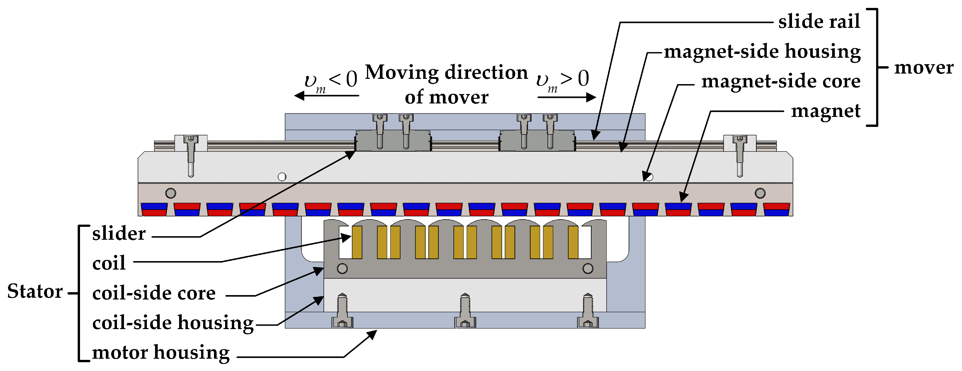
The motor selected in this document is a three-phase motor with 6 coils and 7-pole magnets. The magnets and their cores are selected as the mover, while the coils and their cores are used as the stator, paired with an 8 mm high stainless steel miniature linear rail. The slide rail serves as the mover and is mounted on the magnet-side housing, while the two sliders act as the stator and are fixed together with the coil-side housing on the motor housing. The cross-sectional view of the motor structure is shown in
Figure 1.
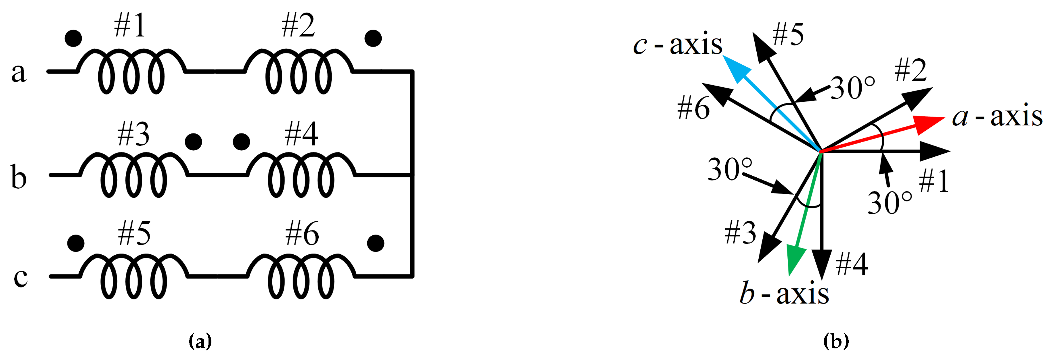
The electrical angle of each coil differs by 210°, and the electrical angle distribution is shown in
Table 1. The winding phase sequence and direction are determined according to the electrical angle distribution, with #2, #3, and #6 being reverse-connected to reverse the current direction. The wiring and vector diagram are shown in
Figure 2.
The permanent-magnet linear motor described in this document is designed with a focus on miniaturization, high speed, and high acceleration. The maximum movement speed is 1.0 m/s, and the total travel distance is 80 mm. The schematic diagram of the motor dimensions shown in
Figure 3, and detailed motor specifications and dimensions are provided in
Table 2.
2.2. Auxiliary Core To Improve End Effects
To address the end effects of the linear motor, an improvement with auxiliary core was proposed. Simulations and analyses of the back-EMF were conducted at a speed of 1.0 m/s with 80 turns per coil. The results, shown in
Table 3 indicate that the three-phase back-EMF is balanced, with a peak voltage difference of 0.002 V between phase a and phase b.
2.3. Electromagnetic Force Analysis And Improvement
A current control analysis was conducted with a peak current of 1 A per phase, resulting in an average electromagnetic force of 5.46 N, as shown in
Figure 4. The harmonic components are predominantly even-order harmonics, and after improvement, the electromagnetic force increased and the harmonic content significantly improved. The harmonic amplitude of the electromagnetic force and its phase angle after improvement are shown in
Table 4, and these data will serve as key parameters for cogging force improvement in the control strategy discussed in this document.
3. Control Strategy And Simulation Of The Small-Type Permanent-Magnet Linear Motor
3.1. Electromagnetic Force Control Strategy
The relationship between the electromagnetic force command
and the electromagnetic force constant
determines the dq-axes current commands
and
:
using the three-phase current feedback
,
and,
the dq-axes current feedback
and
are obtained through coordinate transformation, and the dq-axes current errors
and
in the mover coordinate system are calculated as follows:
the ideal functions
and
of the dq-axes current regulators in the mover coordinate system in the z-domain are as follows:
where
and
are the proportional-integral gains for the d-axis current controller,
and
are the proportional-integral gains for the q-axis current controller, and
is the controller sampling time. The output of the dq-axes current regulators in the mover coordinate system is as follows:
where
and
are the outputs of the dq-axes current regulators. The dq-axes voltage commands
and
in the mover coordinate system are as follows:
finally,
and
are transformed into the stationary coordinate system’s abc-axes voltages
,
and
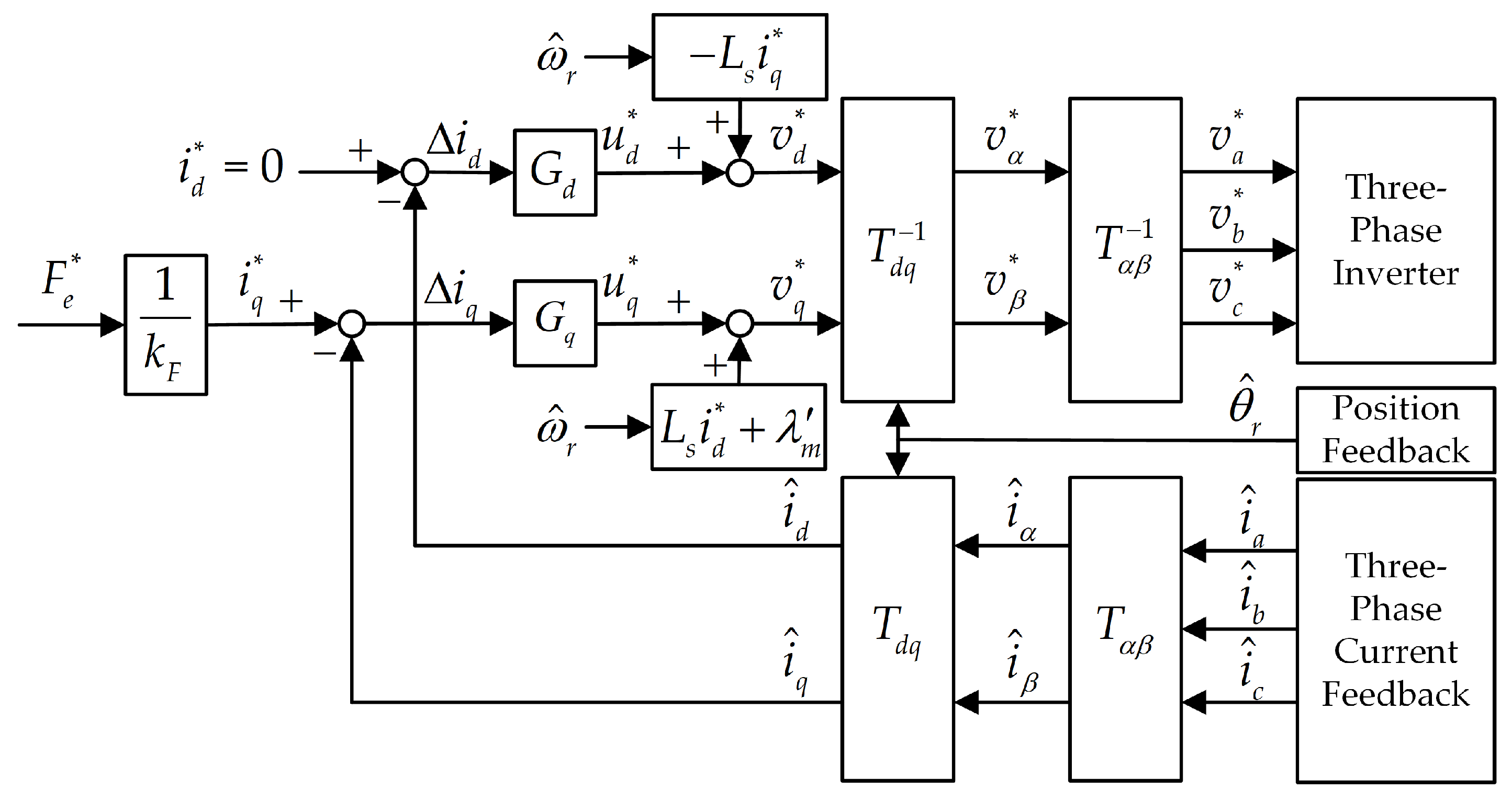
, which are then output via VSVPWM to the inverter, thereby driving the linear motor. The closed-loop control block diagram of the electromagnetic force and its dq-axes current is shown in
Figure 5.
3.2. Cogging Force Improvement Strategy
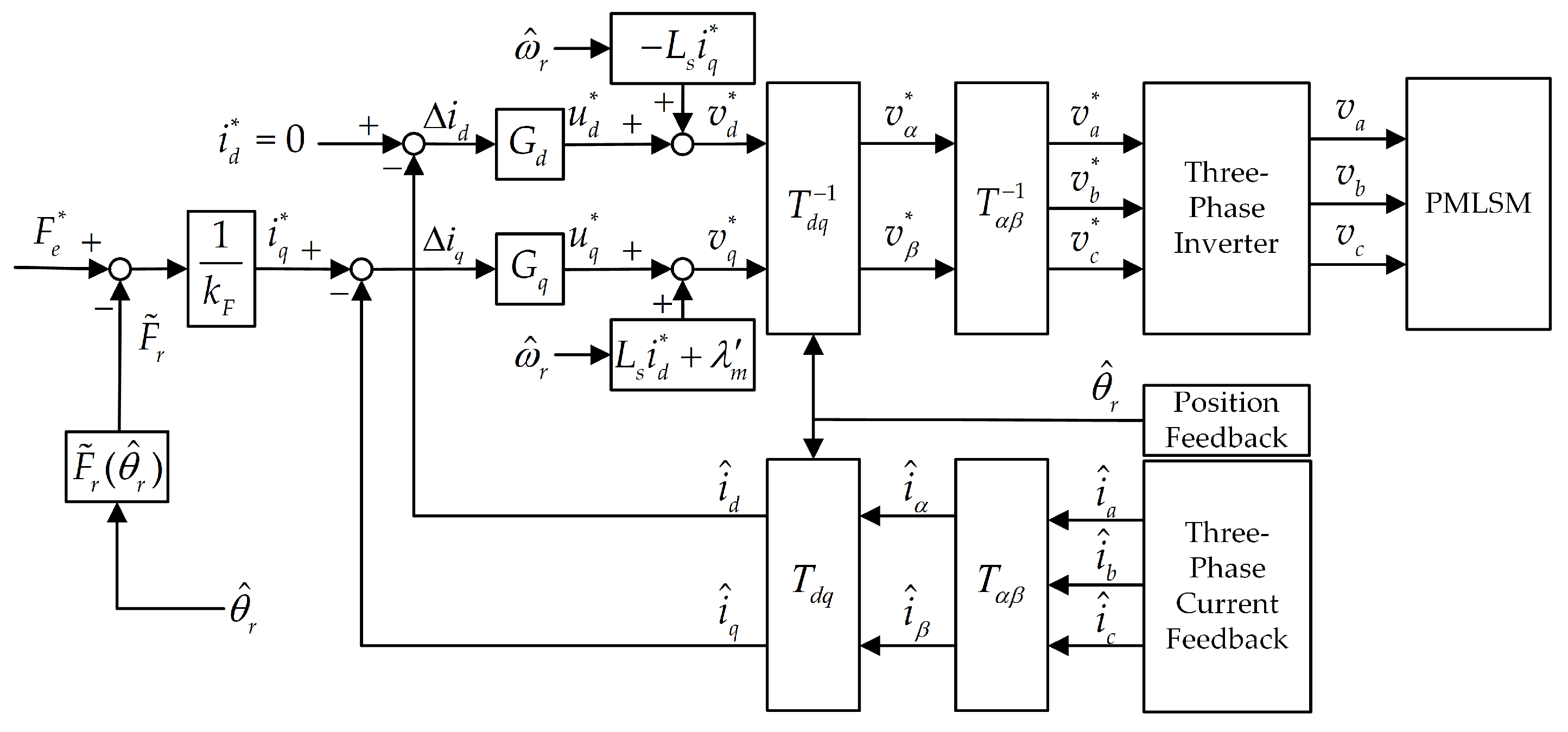
As shown in
Figure 6, cogging force improvement can be achieved by adding the ripple component of the cogging force into the q-axis current command
. The q-axis current command
after incorporating cogging force improvement is:
where
is the electromagnetic force harmonic function, and its function is given by:
where n is the harmonic order,
is the harmonic phase angle, and
is the electromagnetic force harmonic amplitude. Based on the data in
Table 4, the 2nd, 4th, and 6th harmonics are incorporated into the electromagnetic force ripple compensation
as follows:
based on the analysis data in
Table 4,
=6.05,
=0.42,
=0.21,
=119.7,
=238.4 and
=198.7.
3.3. S-Curve Motion Trajectory Control Strategy
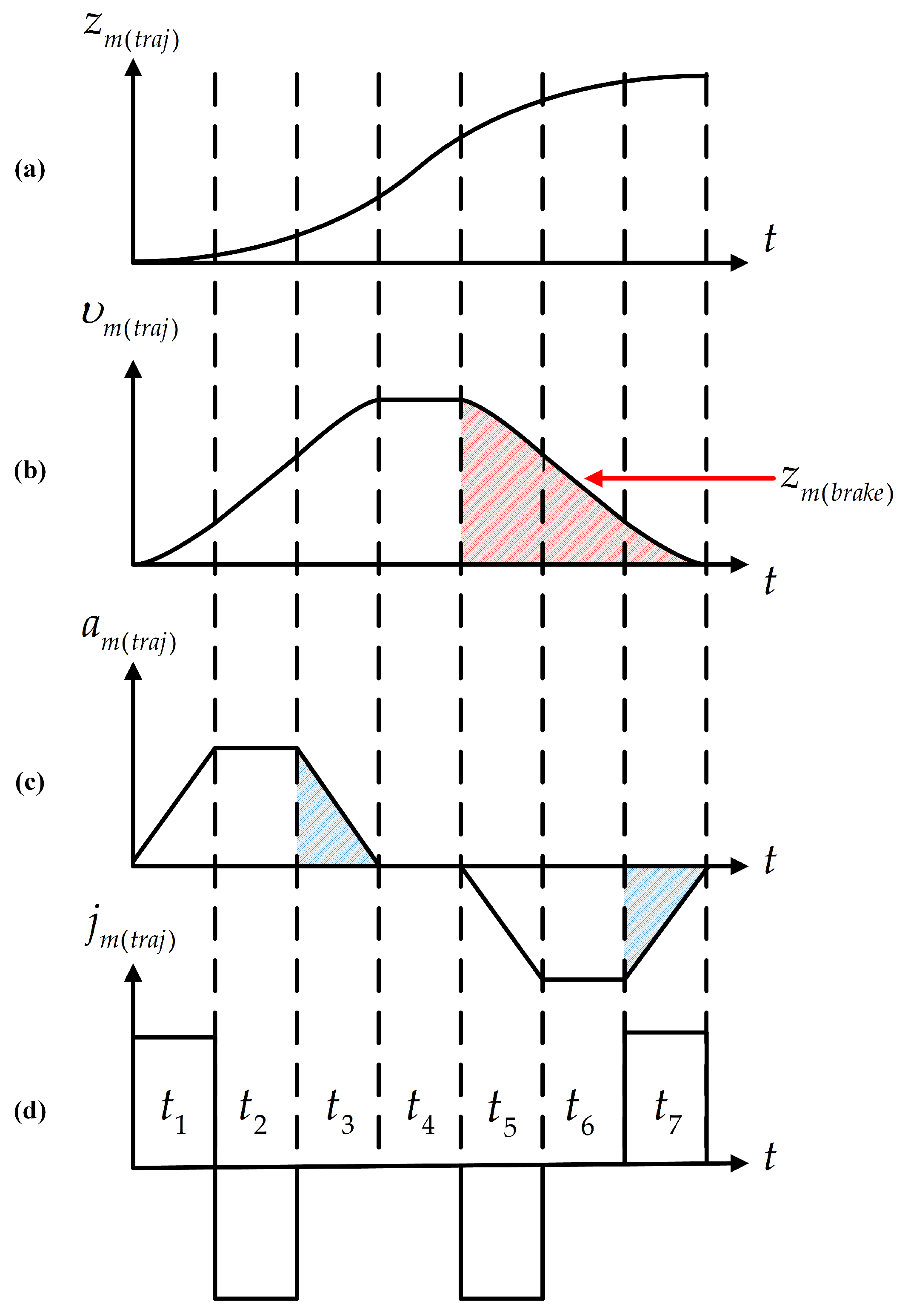
The mover’s position trajectory
, speed trajectory
, acceleration trajectory
, and jerk trajectory
in the S-curve motion trajectory are shown in
Figure 7. The main principle is to add a constant jerk to the acceleration, forming a trapezoidal acceleration curve, which in turn creates an S-curve speed profile. This optimization prevents sudden jerks during acceleration or deceleration, resulting in smoother and more stable position control.
The mover position command
first enters the S-curve motion trajectory to calculate the mover position trajectory command
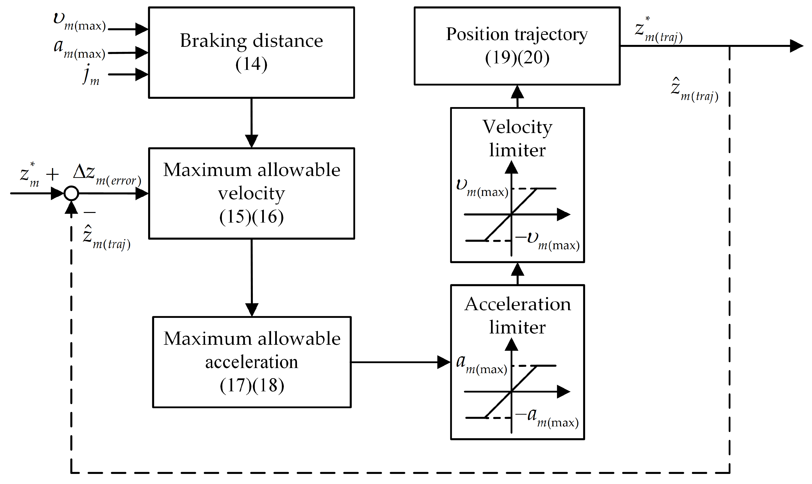
, with the trajectory control block diagram shown in
Figure 8. This process involves first calculating the braking distance for the current speed, then sequentially calculating the maximum allowable speed and maximum allowable acceleration, before entering the acceleration limiter and speed limiter, and finally computing the position trajectory.
The output and judgment formula for the braking distance
are as follows:
where
is the maximum mover speed, and
is the maximum mover acceleration. The output and judgment formula for the maximum allowable speed
are as follows:
where
is the mover position trajectory error. The current speed direction is then determined based on
:
the output of the maximum allowable acceleration
is as follows:
where
is the speed trajectory error. The current acceleration direction is then determined based on
, and the comprehensive output and judgment formula are as follows:
the position trajectory variation
is as follows:
where
is the controller operation cycle. The position trajectory
is as follows:
where
is the position trajectory feedback. The mover position error
is as follows:
where
is the mover position feedback. The mover position regulator function
is as follows:
where
,
and
are the proportional-integral-derivative (PID) controller gains for mover position control. The output of the mover position regulator
is as follows:
where
is the electromagnetic force command. By inputting
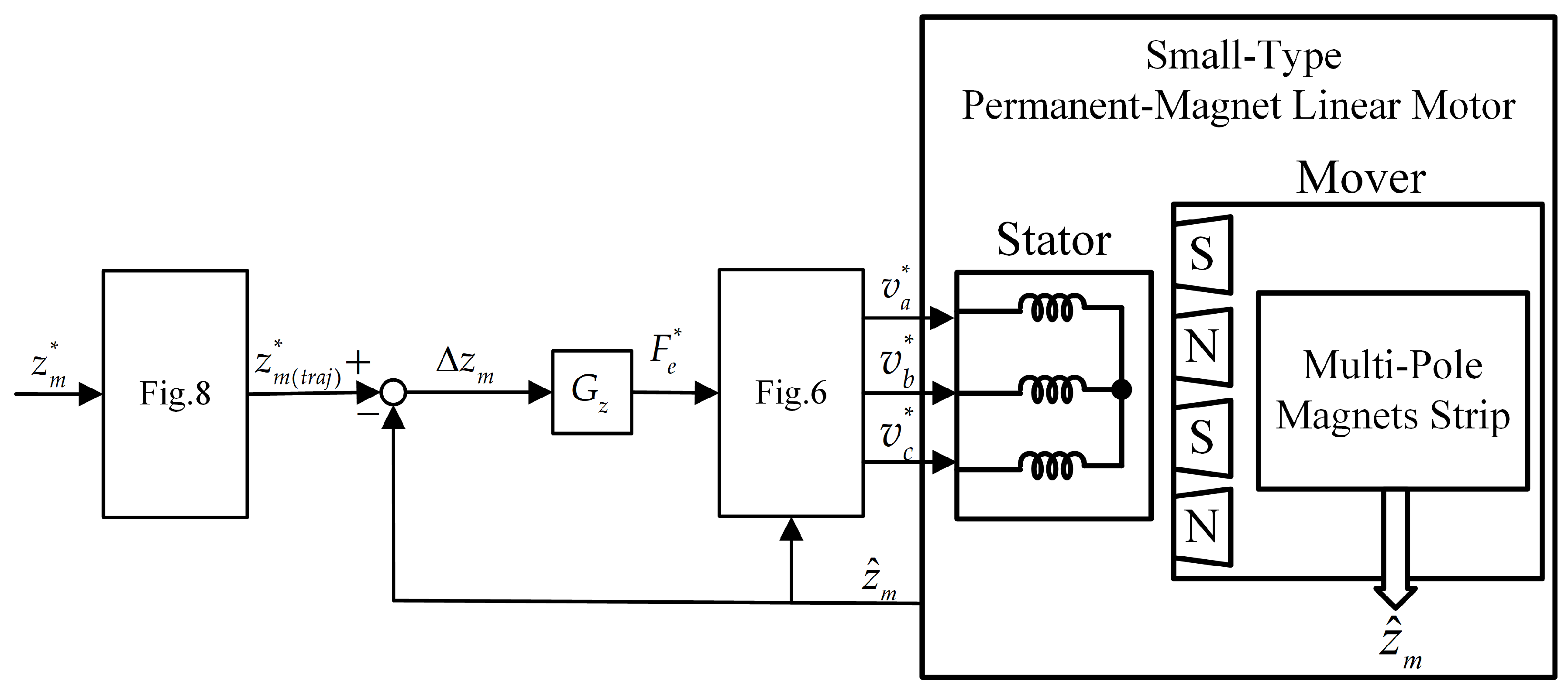
into the current closed-loop, the position closed-loop control is completed, as shown in
Figure 9.
3.4. Control Strategy Simulation
3.4.1. Electromagnetic Force Control Simulation
Based on the electromagnetic force control strategy described in
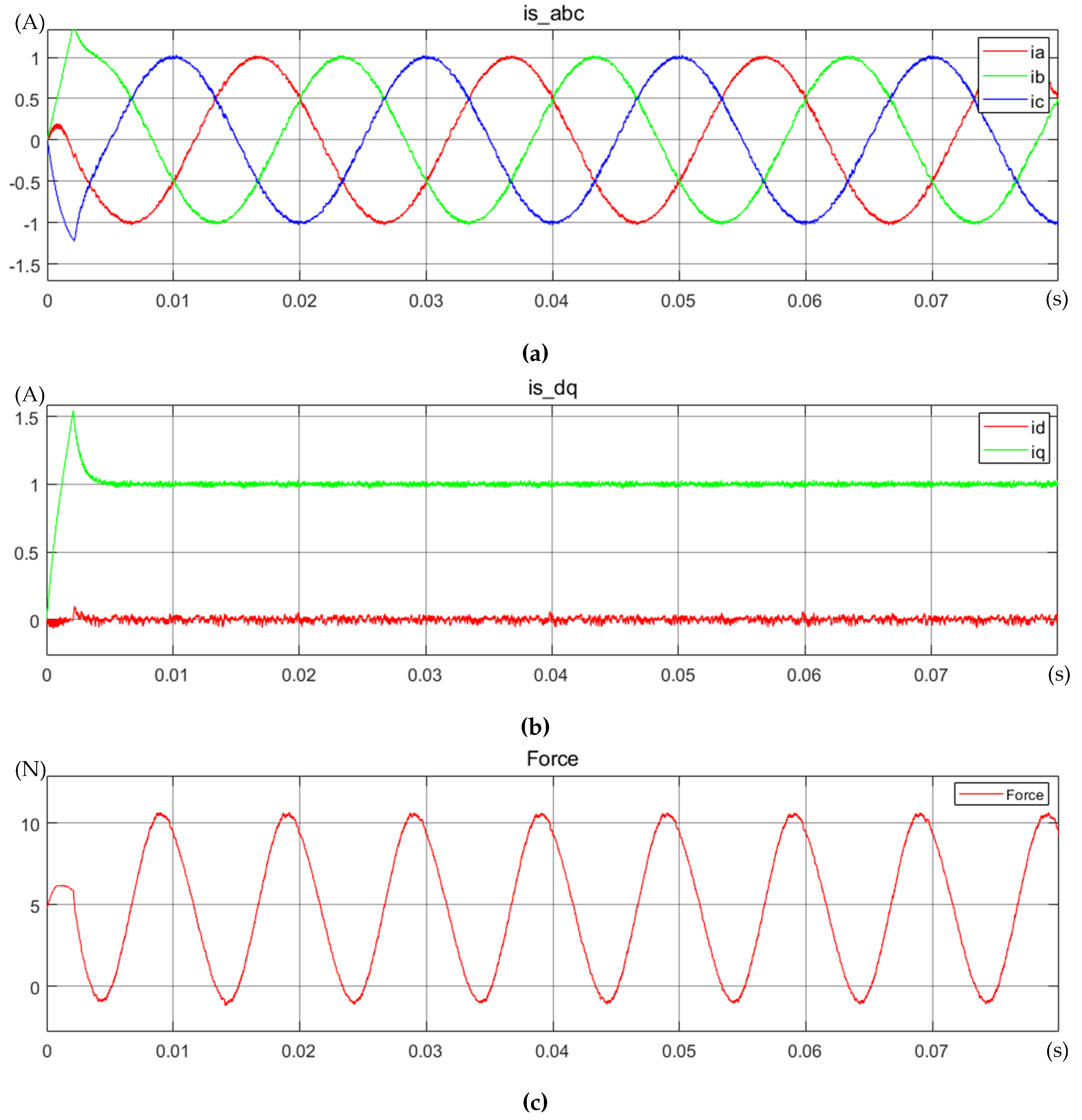
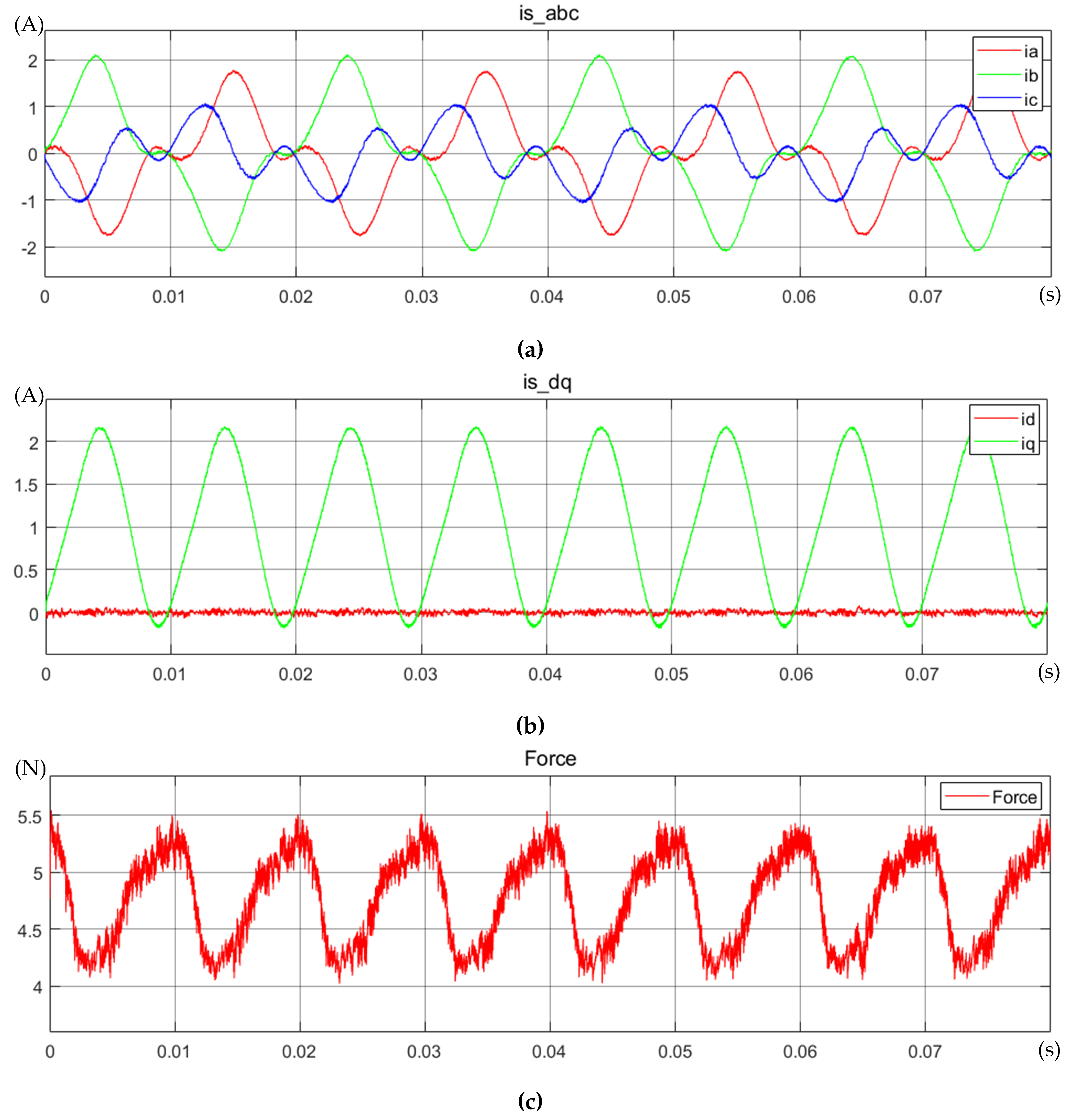
Section 3.1, a MATLAB/Simulink simulation model was established. When an external force drives the linear motor in this document at a speed of 1.0 m/s, and the electromagnetic force command is controlled at
= 5.46 N, the current and magnetic force responses are shown in
Figure 10. The q-axis current feedback
= 1 A, and the electromagnetic force exhibits a stable ripple, consistent with the JMAG simulation, with a magnitude of approximately ± 6 N.
3.4.2. Cogging Force Improvement Simulation
Based on the cogging force improvement strategy described in
Section 3.2, a MATLAB/Simulink simulation model was established. When an external force drives the linear motor in this document at a speed of 1.0 m/s, and the electromagnetic force command is controlled at
= 5.46 N, the current and magnetic force responses are shown in
Figure 11. The electromagnetic force ripple is significantly reduced to approximately ±0.5 N.
3.4.3. S-Curve Motion Trajectory Control Simulation
Based on the S-curve motion trajectory control strategy described in
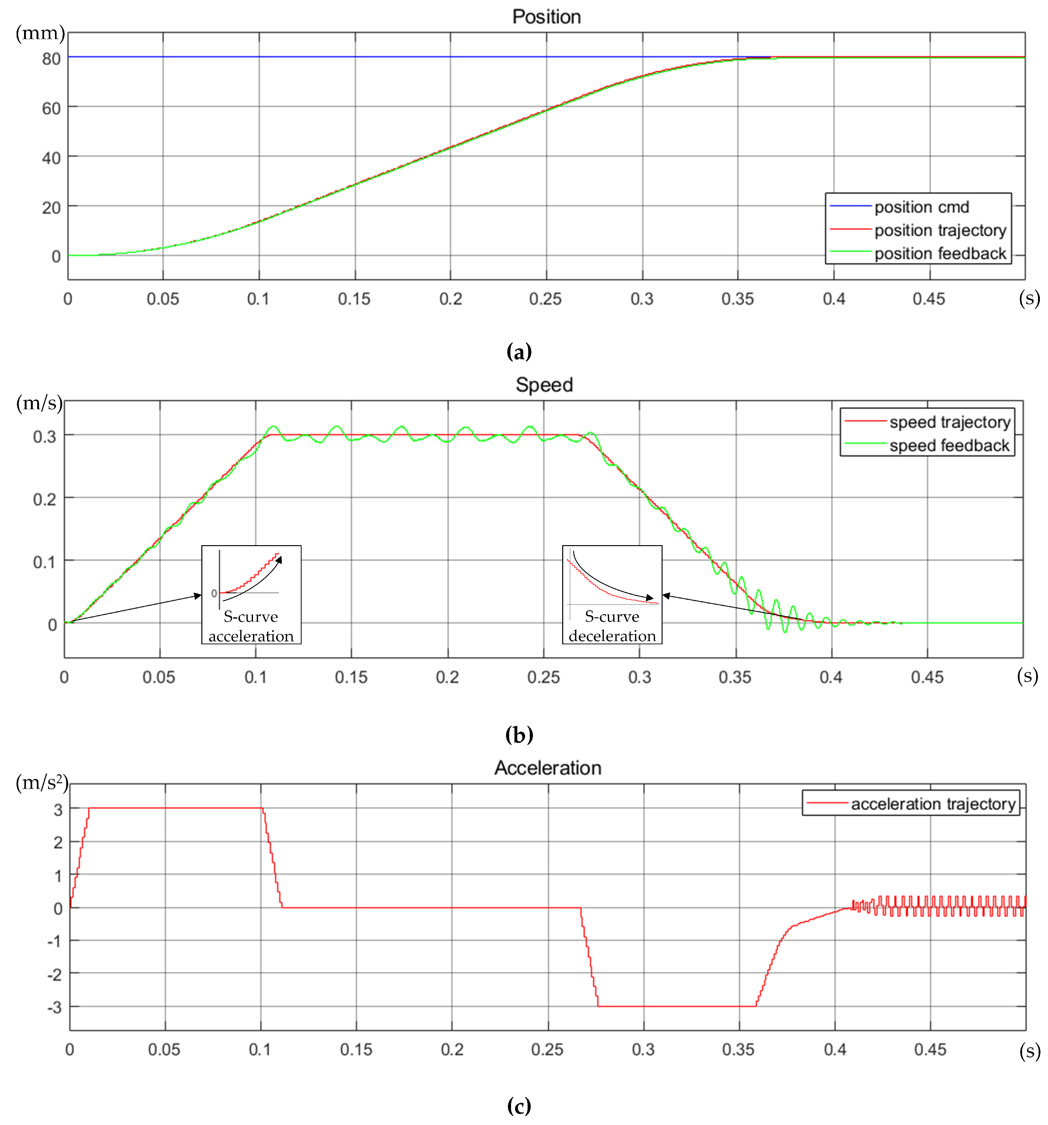
Section 3.3, a MATLAB/Simulink simulation model was established. When the mover position command is controlled at
= 80 mm, the position and speed responses are shown in
Figure 12. The speed trajectory exhibits an S-curve motion, the position feedback nearly overlaps with the position trajectory, and there is a slight deviation between the speed trajectory and the speed feedback curve.
4. System Testing
4.1. Drive System Structure
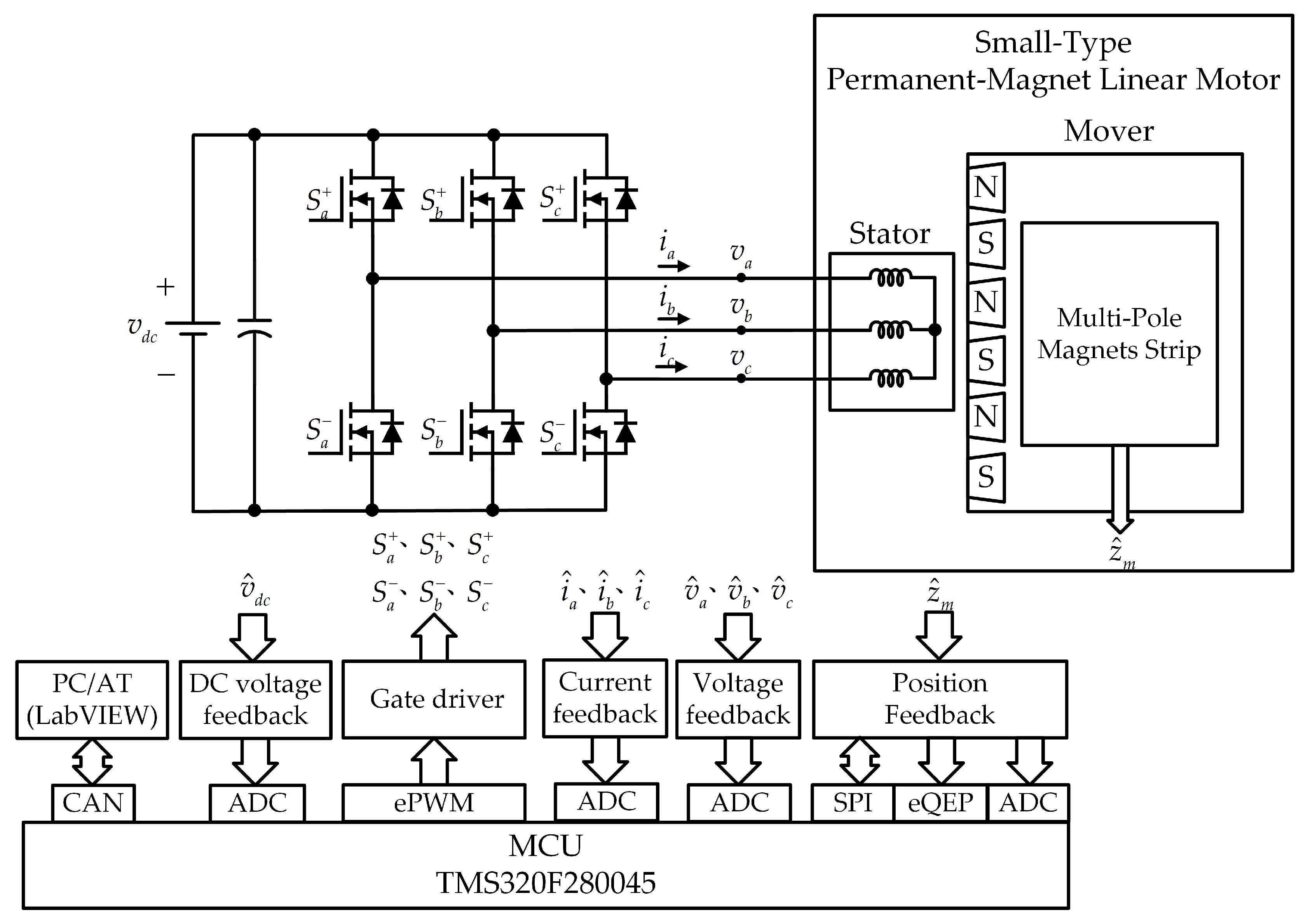
Uses the Texas Instruments (TI) C2000 series 32-bit microcontroller (MCU) TMS320F280 045 as the control core. The enhanced pulse width modulator (ePWM) within the MCU controls the switching circuits of the three-phase inverter. A 12-bit analog-to-digital converter (ADC) measures voltage and current feedback. The enhanced quadrature encoder pulse (eQEP) and serial peripheral interface (SPI) measure feedback from the multi-pole magnets strip, with the absolute position of the multi-pole magnets strip calibrated using the ADC. A controller area network (CAN) provides control for external devices. The configuration of the small-type permanent-magnet linear motor includes the stator, mover, and multi-pole magnets strip. Small-type permanent-magnet linear motor driver block diagram is shown in
Figure 13.
The magnetic encoder paired with the multi-pole magnets strip outputs at 12-bit resolution, with a resolution of 0.488
m/step and a maximum linear movement speed of 2345 mm/s. Additionally, the linear Hall effect sensor DRV5055A1 is used to sense the absolute position of the multi-pole magnets strip. The final physical implementation of the driver is shown in
Figure 14.
4.2. Linear Motor Fabrication And Parameter Measurement
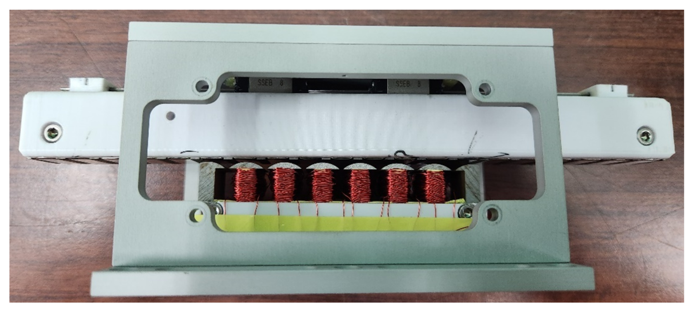
Based on the specifications of the small-type permanent-magnet linear motor described earlier, the physical implementation is shown in
Figure 15. The measured motor parameters are as follows the equivalent resistance
of each phase winding is 3.054, 2.985, and 2.976
, with an average of approximately 3.0
; the equivalent inductance
of each phase winding is 1.992, 1.967, and 1.982 mH, with an average of approximately 1.98 mH.
The small-type permanent-magnet linear motor pull-test platform is shown in
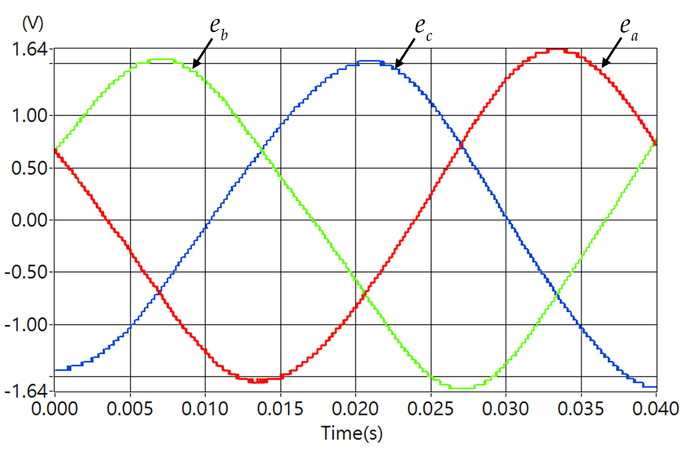
Figure 16. It is used to measure the motor’s back-EMF or motor loading. A pull-test was conducted at
= 25 Hz(
= 0.5 m/s), and the back-EMF phase voltage of the generator side was measured as shown in
Figure 17. The peak value of the back-EMF phase voltage
= 1.64 V, and the flux linkage of the mover magnets equivalent to the stator
was
According to Equation (
24),
is calculated to be 0.0104 V/(rad/s).
4.3. Electromagnetic Force Testing
After removing the generator side from the small-type permanent-magnet linear motor pull-test platform, a fixed pulley was installed and secured to the platform. A steel wire with a diameter of 0.3 mm was used to connect one end to the tail of the linear motor, while the other end was passed through the fixed pulley and hung vertically downward. Weights were added as needed for the test. The electromagnetic force test platform for the linear motor is shown in
Figure 18.
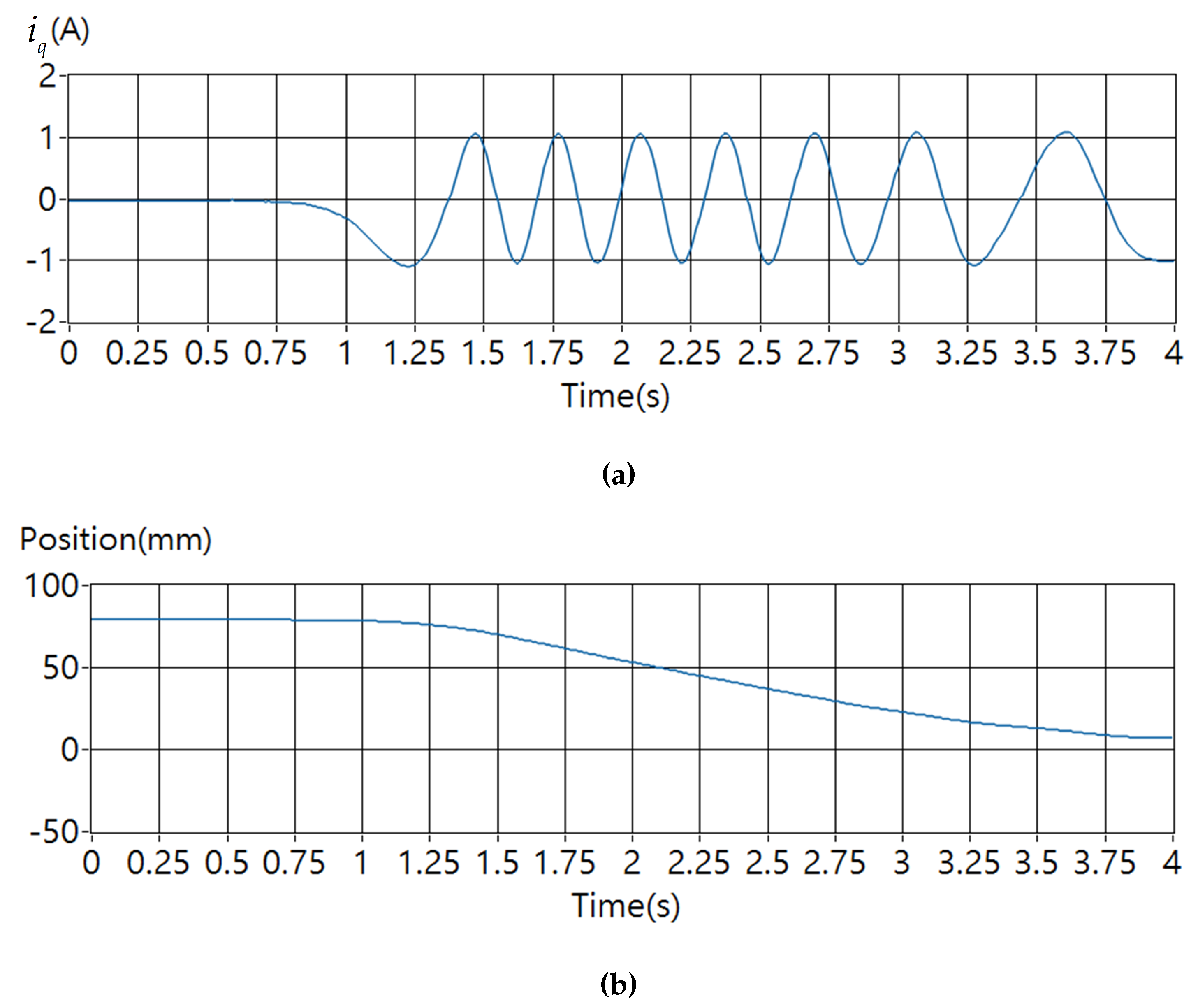
Before implementing the cogging force improvement strategy, an external load greater than the maximum cogging force was required to move the linear motor. After implementing the cogging force improvement strategy, the linear motor can move smoothly with the application of an external load. When the cogging force improvement strategy is applied with position closed-loop control, the maximum load is 4.90 N. When the cogging force is added and
= 0.0 N is controlled, the q-axis current feedback
for the externally applied push force adjusts with the mover position to provide approximately 1.05 A of current compensation, as shown in
Figure 19, consistent with the simulation results.
4.4. S-Curve Motion Trajectory Control Testing
Based on the S-curve motion trajectory control strategy proposed in
Section 3.3, linear motor position closed-loop control tests were conducted. With a maximum speed of 0.3 m/s, maximum acceleration of 3 m/s
2, and maximum jerk of 300 m/s
3, the motor was moved from 20 mm to 100 mm, then back to 20 mm, as shown in
Figure 20. After reaching steady-state, the maximum position error was about 5.0
m, and when the speed reached stability, the speed fluctuation was about 0.03 m/s.
5. Conclusions
This paper designed and fabricated a small-type permanent-magnet linear motor and its driver for automation applications. The small-type permanent-magnet linear motor designed in this paper uses embedded magnets, which enhance electromagnetic force and mechanical strength while effectively reducing magnetic reluctance caused by air gaps. Through the analysis and improvement of magnetic flux lines, magnetic flux density, back-EMF, and electromagnetic force, a three-phase, 6-coil, 7-pole configuration was ultimately selected, with auxiliary cores added to reduce end effects. At a speed of 1.0 m/s, this configuration achieved a three-phase fundamental wave voltage peak of 3.621 V, a low-order THD of only 0.49%, and a phase voltage peak error of -0.002 V, completing a motor model design with low harmonic back-EMF and effectively reduced end effects. The parameter measurements of the fabricated small-type permanent-magnet linear motor show stable three-phase performance, including an equivalent resistance of approximately 3.0 per phase winding and an equivalent inductance approximately 1.98 mH per phase winding. The position feedback device uses a magnetic encoder feedback system with a resolution of 488 nm, achieving extremely high positioning accuracy.
In terms of control strategies, this paper adopted voltage space vector control, electromagnetic force control, cogging force improvement, and S-curve motion trajectory control strategies, all of which effectively improved the precision and stability of motion control. The test results verified the effectiveness of the cogging force improvement strategy and the S-curve motion trajectory control strategy, significantly enhancing motion stability and accuracy. After incorporating the cogging force improvement strategy, the maximum electromagnetic force was 4.90 N, and the q-axis current provided approximately 1.05 A of current compensation based on the mover position. Additionally, the S-curve motion trajectory control demonstrated extremely high and stable response speed.
Author Contributions
Conceptualization, C.-H.H. and J.-C.H.; methodology, C.-H.H.; software, C.-H.H.; validation, C.-H.H. and J.-C.H.; formal analysis, C.-H.H.; investigation, C.-H.H. and J.-C.H.; resources, C.-H.H. and J.-C.H.; data curation, C.-H.H.; writing—original draft preparation, C.-H.H.; writing—review and editing, C.-H.H. and J.-C.H.; visualization, C.-H.H.; supervision, J.-C.H.; project administration, J.-C.H.; funding acquisition, J.-C.H. All authors have read and agreed to the published version of the manuscript.
Funding
This research received no external funding.
Institutional Review Board Statement
Not applicable.
Informed Consent Statement
Not applicable.
Conflicts of Interest
The authors declare no conflict of interest.
References
- Chung, S.U.; Kim, J.M. Double-Sided Iron-Core PMLSM Mover Teeth Arrangement Design for Reduction of Detent Force and Speed Ripple. IEEE Transactions on Industrial Electronics 2016, 63, 3000–3008. [Google Scholar] [CrossRef]
- Zhang, Z.; Shi, L.; Wang, K.; Li, Y. Characteristics Investigation of Single-sided Ironless PMLSM Based on Halbach Array for Medium-Speed Maglev Train. CES Transactions on Electrical Machines and Systems 2017, 1, 375–382. [Google Scholar] [CrossRef]
- Hwang, C.C.; Li, P.L.; Liu, C.T. Optimal Design of a Permanent Magnet Linear Synchronous Motor With Low Cogging Force. IEEE Transactions on Magnetics 2012, 48, 1039–1042. [Google Scholar] [CrossRef]
- Zhu, Y.W.; Cho, Y.H. Thrust Ripples Suppression of Permanent Magnet Linear Synchronous Motor. IEEE Transactions on Magnetics 2007, 43, 2537–2539. [Google Scholar] [CrossRef]
- Zhu, Y.W.; Jin, S.M.; Chung, K.S.; Cho, Y.H. Control-Based Reduction of Detent Force for Permanent Magnet Linear Synchronous Motor. IEEE Transactions on Magnetics 2009, 45, 2827–2830. [Google Scholar] [CrossRef]
- Lu, Q.; Wu, B.; Yao, Y.; Shen, Y.; Jiang, Q. Analytical Model of Permanent Magnet Linear Synchronous Machines Considering End Effect and Slotting Effect. IEEE Transactions on Energy Conversion 2020, 35, 139–148. [Google Scholar] [CrossRef]
- Hu, H.; Zhao, J.; Liu, X.; Guo, Y. Magnetic Field and Force Calculation in Linear Permanent-Magnet Synchronous Machines Accounting for Longitudinal End Effect. IEEE Transactions on Industrial Electronics 2016, 63, 7632–7643. [Google Scholar] [CrossRef]
- Zhang, C.; Zhang, L.; Huang, X.; Yang, J.; Shen, L. Research on the Method of Suppressing the End Detent Force of Permanent Magnet Linear Synchronous Motor Based on Stepped Double Auxiliary Pole. IEEE Access 2020, 8, 112539–112552. [Google Scholar] [CrossRef]
- Shin, K.H.; Kim, K.H.; Hong, K.; Choi, J.Y. Detent Force Minimization of Permanent Magnet Linear Synchronous Machines Using Subdomain Analytical Method Considering Auxiliary Teeth Configuration. IEEE Transactions on Magnetics 2017, 53, 1–4. [Google Scholar] [CrossRef]
- Kim, S.J.; Park, E.J.; Jung, S.Y.; Kim, Y.J. Optimal Design of Reformed Auxiliary Teeth for Reducing End Detent Force of Stationary Discontinuous Armature PMLSM. IEEE Transactions on Applied Superconductivity 2016, 26, 1–5. [Google Scholar] [CrossRef]
- Zhang, H.; Kou, B.; Jin, Y.; Zhang, H. Investigation of Auxiliary Poles Optimal Design on Reduction of End Effect Detent Force for PMLSM With Typical Slot–Pole Combinations. IEEE Transactions on Magnetics 2015, 51, 1–4. [Google Scholar] [PubMed]
- Cui, L.; Zhang, H.; Jiang, D. Research on High Efficiency V/f Control of Segment Winding Permanent Magnet Linear Synchronous Motor. IEEE Access 2019, 7, 138904–138914. [Google Scholar] [CrossRef]
- Zhao, Z.; Hu, C.; Wang, Z.; Wu, S.; Liu, Z.; Zhu, Y. Back EMF-Based Dynamic Position Estimation in the Whole Speed Range for Precision Sensorless Control of PMLSM. IEEE Transactions on Industrial Informatics 2023, 19, 6525–6536. [Google Scholar] [CrossRef]
- Wen, T.; Wang, Z.; Xiang, B.; Han, B.; Li, H. Sensorless Control of Segmented PMLSM for Long-Distance Auto-Transportation System Based on Parameter Calibration. IEEE Access 2020, 8, 102467–102476. [Google Scholar] [CrossRef]
- Sun, X.; Wu, M.; Yin, C.; Wang, S.; Tian, X. Multiple-Iteration Search Sensorless Control for Linear Motor in Vehicle Regenerative Suspension. IEEE Transactions on Transportation Electrification 2021, 7, 1628–1637. [Google Scholar] [CrossRef]
- Xu, W.; Liao, K.; Ge, J.; Qu, G.; Cheng, S.; Wang, A.; Boldea, I. Improved Position Sensorless Control for PMLSM via an Active Disturbance Rejection Controller and an Adaptive Full-Order Observer. IEEE Transactions on Industry Applications 2023, 59, 1742–1753. [Google Scholar] [CrossRef]
- Wang, M.; Li, L.; Pan, D.; Tang, Y.; Guo, Q. High-Bandwidth and Strong Robust Current Regulation for PMLSM Drives Considering Thrust Ripple. IEEE Transactions on Power Electronics 2016, 31, 6646–6657. [Google Scholar] [CrossRef]
- Kung, Y.S. Design and Implementation of a High-Performance PMLSM Drives Using DSP Chip. IEEE Transactions on Industrial Electronics 2008, 55, 1341–1351. [Google Scholar] [CrossRef]
- Yuan, H.; Zhao, X. Adaptive Jerk Control and Modified Parameter Estimation for PMLSM Servo System With Disturbance Attenuation Ability. IEEE/ASME Transactions on Mechatronics 2023, 28, 164–174. [Google Scholar] [CrossRef]
- Rew, K.H.; Kim, K.S. A Closed-Form Solution to Asymmetric Motion Profile Allowing Acceleration Manipulation. IEEE Transactions on Industrial Electronics 2010, 57, 2499–2506. [Google Scholar] [CrossRef]
- Bai, Y.; Chen, X.; Sun, H.; Yang, Z. Time-Optimal Freeform S-Curve Profile Under Positioning Error and Robustness Constraints. IEEE/ASME Transactions on Mechatronics 2018, 23, 1993–2003. [Google Scholar] [CrossRef]
- Ha, C.W.; Rew, K.H.; Kim, K.S.; Kim, S. Tuning the S-curve Motion Profile in Short Distance Case. 2013 American Control Conference, pp. 4975–4980.
- Ha, C.W.; Rew, K.H.; Kim, K.S. Robust Zero Placement for Motion Control of Lightly Damped Systems. IEEE Transactions on Industrial Electronics 2013, 60, 3857–3864. [Google Scholar] [CrossRef]
Figure 1.
Cross-sectional view of the motor structure.
Figure 1.
Cross-sectional view of the motor structure.
Figure 2.
Three-phase motor with 6 coils and 7-pole magnets: (a) wiring; (b) vector.
Figure 2.
Three-phase motor with 6 coils and 7-pole magnets: (a) wiring; (b) vector.
Figure 3.
Motor dimensions schematic diagram.
Figure 3.
Motor dimensions schematic diagram.
Figure 4.
Electromagnetic force from current control analysis with a peak current of 1 A per phase.
Figure 4.
Electromagnetic force from current control analysis with a peak current of 1 A per phase.
Figure 5.
Permanent-magnet linear motor electromagnetic force and dq-axes current closed-loop control block diagram.
Figure 5.
Permanent-magnet linear motor electromagnetic force and dq-axes current closed-loop control block diagram.
Figure 6.
Permanent-magnet linear motor closed-loop control block diagram of the dq-axes current with electromagnetic force ripple compensation.
Figure 6.
Permanent-magnet linear motor closed-loop control block diagram of the dq-axes current with electromagnetic force ripple compensation.
Figure 7.
Speed trajectory during S-curve motion: (a); (b); (c); (d).
Figure 7.
Speed trajectory during S-curve motion: (a); (b); (c); (d).
Figure 8.
S-curve motion trajectory control block diagram
Figure 8.
S-curve motion trajectory control block diagram
Figure 9.
Permanent-magnet linear motor position closed-loop control block diagram.
Figure 9.
Permanent-magnet linear motor position closed-loop control block diagram.
Figure 10.
Simulation of electromagnetic force command = 5.46 N: (a) phase current of the linear motor; (b) dq-axes current; (c) electromagnetic force.
Figure 10.
Simulation of electromagnetic force command = 5.46 N: (a) phase current of the linear motor; (b) dq-axes current; (c) electromagnetic force.
Figure 11.
Simulation of electromagnetic force command = 5.46 N with ripple compensation: (a) phase current of the linear motor; (b) dq-axes current; (c) electromagnetic force.
Figure 11.
Simulation of electromagnetic force command = 5.46 N with ripple compensation: (a) phase current of the linear motor; (b) dq-axes current; (c) electromagnetic force.
Figure 12.
Simulation of S-curve motion trajectory for mover position command = 80 mm: (a) position; (b) speed; (c) acceleration.
Figure 12.
Simulation of S-curve motion trajectory for mover position command = 80 mm: (a) position; (b) speed; (c) acceleration.
Figure 13.
Small-type permanent-magnet linear motor driver block diagram
Figure 13.
Small-type permanent-magnet linear motor driver block diagram
Figure 14.
Physical implementation of the driver circuit: (a) front view; (b) rear view.
Figure 14.
Physical implementation of the driver circuit: (a) front view; (b) rear view.
Figure 15.
Small-type permanent-magnet linear motor physical implementation.
Figure 15.
Small-type permanent-magnet linear motor physical implementation.
Figure 16.
Small-type permanent-magnet linear motor pull-test platform.
Figure 16.
Small-type permanent-magnet linear motor pull-test platform.
Figure 17.
Small-type permanent-magnet linear motor back-EMF.
Figure 17.
Small-type permanent-magnet linear motor back-EMF.
Figure 18.
Electromagnetic force test platform.
Figure 18.
Electromagnetic force test platform.
Figure 19.
With cogging force compensation and = 0.0 N control: (a) q-axis current feedback (b) position feedback .
Figure 19.
With cogging force compensation and = 0.0 N control: (a) q-axis current feedback (b) position feedback .
Figure 20.
S-curve motion trajectory testing: (a) position curve. (b) speed curve.
Figure 20.
S-curve motion trajectory testing: (a) position curve. (b) speed curve.
Table 1.
Electrical angle distribution for each coil in the three-phase motor with 6 coils and 7-pole magnets.
Table 1.
Electrical angle distribution for each coil in the three-phase motor with 6 coils and 7-pole magnets.
| Number of coil |
#1 |
#2 |
#3 |
#4 |
#5 |
#6 |
| Electrical angle |
0° |
210° |
60° |
270° |
120° |
330° |
| (30°) |
(240°) |
(150°) |
| Number of phases |
a+ |
a- |
b- |
b+ |
c+ |
c- |
Table 2.
Motor material and dimensions.
Table 2.
Motor material and dimensions.
| Mover |
trapezoidal magnet |
material |
sintered NdFeB magnet N35 |
| width of the long side
|
8 |
| width of the short side
|
7 |
| height
|
4 |
| pole pitch
|
10 |
| core |
material |
silicon steel sheet 50CS600 |
| length
|
200 |
| width
|
17 |
| height
|
10 |
| air gap
|
1 |
| Stator |
coil |
material |
polyurethane enamelled copper wire |
| wire diameter
|
0.25 |
| length
|
23 |
| width
|
10.67 |
| height
|
10 |
| core |
material |
silicon steel sheet 50CS600 |
| length
|
86.33 |
| width
|
17 |
| height
|
18 |
| front iron height
|
2 |
| back iron height
|
6 |
Table 3.
Adding auxiliary core back-EMF analysis.
Table 3.
Adding auxiliary core back-EMF analysis.
| Auxiliary core |
Without |
With |
| Phase a back-EMF |
fundamental(V) |
3.735 |
3.619 |
| THD(%) |
3.93 |
0.58 |
| Phase b back-EMF |
fundamental(V) |
3.929 |
3.621 |
| THD(%) |
0.68 |
0.40 |
| Peak back-EMF difference between phase a and b(V) |
-0.194 |
-0.002 |
Table 4.
Harmonic amplitude of electromagnetic force and its phase angle.
Table 4.
Harmonic amplitude of electromagnetic force and its phase angle.
| Harmonic order |
Harmonic amplitude(N) |
Phase angle(°) |
| 2 |
6.05 |
119.7 |
| 4 |
0.42 |
238.4 |
| 6 |
0.21 |
198.7 |
| 8 |
0.08 |
-53.6 |
|
Disclaimer/Publisher’s Note: The statements, opinions and data contained in all publications are solely those of the individual author(s) and contributor(s) and not of MDPI and/or the editor(s). MDPI and/or the editor(s) disclaim responsibility for any injury to people or property resulting from any ideas, methods, instructions or products referred to in the content. |
© 2024 by the authors. Licensee MDPI, Basel, Switzerland. This article is an open access article distributed under the terms and conditions of the Creative Commons Attribution (CC BY) license (http://creativecommons.org/licenses/by/4.0/).
