Submitted:
11 September 2024
Posted:
12 September 2024
You are already at the latest version
Abstract
Keywords:
1. Introduction
| Property | EAP | SMA | EAC | Reference |
|---|---|---|---|---|
| Force [MPa] | 0.1–25 | 200 | 30–40 | [3] |
| Actuation strain | Over 300% | <8% [short Typically 0.1–0.3 % fatigue life] |
Typically 0.1–0.3 % | [2,3] |
| Density | 1–2.5 g/cc | 5–6 g/cc | 6–8 g/c | [3] |
| Consumed power | m-Watts | Watts | Watts | [3] |
| Reaction speed | µsec to min | msec to min | µsec to sec | [2,3] |
| Drive voltage | Ionic EAP: 1–7 V 5-Volt 50–800 V Electronic EAP: 10–150 V/µm | 5-Volt | 50–800 V | [3] |
| Fracture behavior | Resilient, elastic | Resilient, Fragile elastic | Fragile | [3] |
| Property | Electrostatic silicone elastomer | Polymer Electrostrictor | Single Crystal Electrostrictor | Single Crystal Magnetostrictor | Reference |
|---|---|---|---|---|---|
| Actuation strain | 100% | 4% | 1.7% | 2% | [4,8] |
| Blocking area | 0.2 MPa | 0.8 MPa | 65 MPa | 100 MPa | [5,6] |
| Reaction speed | msec | µsec | µsec | µsec | [8] |
| Density | 1.5 g/cc | 3 g/cc | 7.5 g/cc | 9.2 g/cc | [8] |
| Drive field | 144 V/µm | 150 V/µm | 2 V/µm | 2500 Oe | [6] |
| Fracture toughness | Large | Large | Low | Large | [7] |
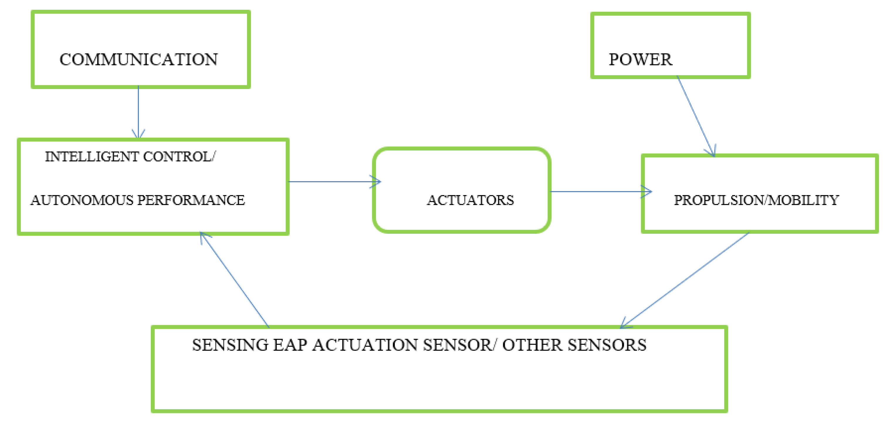
1.1. Ionic Electroactive Polymers
1.2. Ionic EAP Characterization
| Actuator | Working Principle | Advantages | Disadvantages | Example |
|---|---|---|---|---|
| Electrorheological fluids | In the presence of electric field their viscosity changes, inducing dipole moments. | Induce haptic mechanism | Requires high voltage | polymer particles in fluorosilicone base oil |
| Conductive Polymers | When voltage is applied due to oxidation or reduction reaction there is a flow of ion depending on the cell polarity. | With low voltage induce large force. Can be used as biocompatible device. | Under the fatigue loading a cyclic deformation is shown. | Polypyrrole, Polyethylenedioxythiophene, Poly[p-phenylene vinylene]s, Polyaniline, and Polythiophenes. |
| Ionic Gels | On applying a voltage movement of hydrogen ions is there which simulates with chemical reaction according to acid or base. | Low voltage required for operation. High compatibility for biological muscles. |
Very thin film required for operation. | Poly[vinyl alcohol] gel with dimethyl sulfoxide |
| IPMC | Movement of positive ions within fixed surface. | Low voltage. Provide all kind of bending on application of force. |
Low frequency response. Permanent displacement due to flow of DC current. |
Nafion® [perfluorosulfonate made by DuPont]. Flemion® [perfluorocaboxylate, made by Asahi Glass, Japan] |
1.4. Actuation of Ionic Polymer Metal Composites

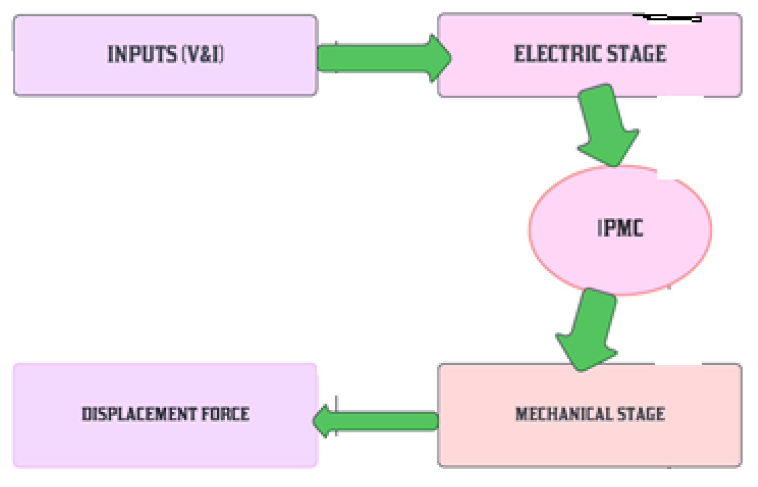
2. Electrode and Ionomer Morphology
3. Electromechanical Analysis of Parylene Coated IPMC Electrode

4. Electromechanical Non Linear Deformation of IPMC
4.1. Black Box Model
4.2. Grey Box Model
4.3. White Box Model
5. Coating Methods for IPMC
5.1. Chemical Vapor Deposition

5.1.1. Parylene

| Parylene C | Parylene D | Parylene N | Parylene HT | Reference | |
|---|---|---|---|---|---|
|
Structure |
Completely linear, high crystalline material, modified by a substitution of chlorine atom for one of the aromatic hydrogen’s. | Completely linear, high crystalline material, modified by a substitution of chlorine atom for two of the aromatic hydrogen’s. |
Completely linear, high crystalline material. |
Completely linear, high crystalline material and replaces the alpha hydrogen atom of parylene N with fluorine. | [43] |
|
Aromatic rings |
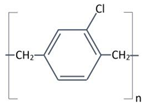
|
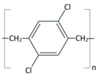
|

|
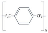
|
[42,43] |
|
Properties |
Useful combination of physical and electrical properties, low permeability to moisture and corrosive gases. | Useful combination of physical and electrical properties, low permeability to moisture and corrosive gases, withstand slightly higher Temperatures. |
Primary dielectric, low dissipation factor, high dielectric strength, low dielectric constant invariant with frequency. | Low coefficient friction, dielectric constant; withstand high temperature, long term UV stability and highest penetrating ability of the four variants. |
[43] |
5.2. Plasma Enhanced Chemical Vapor Deposition Process
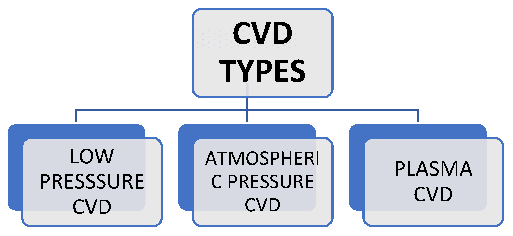
5.3. Comparison between PECVD and CVD
| Property | CVD | PECVD |
|---|---|---|
| Coating Gas | Chemical reaction of precursor gas for deposition process. | The precursor gas is introduced in the deposition chamber for deposition purpose the ionized plasma gas is used. |
| Coating Direction | Multidirectional Deposition process. | Coatings occurs in line site process |
| Coating Adhesion | Good | Excellent |
| Layer thickness | Thicker [1-10 µm]. | Thinner [0.1-2µm] |
| Application | Cutting tools, wear parts & jewelry options. | Cutting parts & medical implants. |
| Coating Properties | Hard, water resistant & corrosion resistant. | Hard, water resistant & low friction. |
| Temperature | Higher deposition temperature. | Lower deposition temperature. |
5.4. PECVD Working & Equipment
5.5. Plasma Treatment for Adhesion Property
5.6. Plasma Treatment of Surface

5.7. Thermal Stability of Parylene Coated Nafion 117 Films
| Parylene Types | Long-Term Temp [°C] Duration = ~10+ Years | Short Term Temperature Duration = ~1 Month | Melting Point Temperature | References |
|---|---|---|---|---|
| Parylene C | 80 | 115 | 290 | [55] |
| Parylene N | 60 | 95 | 420 | [55,56] |
| Parylene D | 100 | 135 | 380 | [55] |
6. Conclusion
Acknowledgements
References
- Bennett M. D. & Leo D. J. 2004. Ionic liquids as stable solvents for ionic polymer transducers. Sensors and Actuators A: Physical, 1151, 79-90.
- Inzelt, G. & Inzelt G. 2012. Classification of electrochemically active polymers. Conducting Polymers: A New Era in Electrochemistry, 7-82.
- Bar-Cohen Y. Xue, T. Joffe, B. Lih S. S., Shahinpoor, M., Harrison, J. S. & Willis, P. 1997, June. Electroactive polymers EAP low-mass muscle actuators. In Smart Structures and Materials 1997: Smart Structures and Integrated Systems Vol. 3041, pp. 697-701. SPIE.
- Goddard, N. J. Singh, K., Hulme, J. P. Malins, C., & Holmes, R. J. 2002. Internally-referenced resonant mirror devices for dispersion compensation in chemical sensing and biosensing applications. Sensors and Actuators A: Physical, 1001, 1-9.
- Zhu T. Zhang J. & Atluri S. N. 1998. A meshless local boundary integral equation LBIE method for solving nonlinear problems. Computational mechanics, 222, 174-186.
- Park, S. E. & Shrout, T. R. 1997. Characteristics of relaxor-based piezoelectric single crystals for ultrasonic transducers. IEEE Transactions on Ultrasonics, Ferroelectrics, and Frequency Control, 445, 1140-1147.
- Hathaway K. B. & Clark A. E. 1993. Magnetostrictive materials. MRS Bulletin, 184, 34-41.
- Ramadan K. S. Sameoto D. & Evoy S. 2014. A review of piezoelectric polymers as functional materials for electromechanical transducers. Smart Materials and Structures, 233, 033001.
- Januin, J. & Stephen, J. 2015. Exploring discourse competence elements in EAP class presentations through document and ethnographic analyses. Procedia-Social and Behavioral Sciences, 208, 157-166. [CrossRef]
- Bar-Cohen Y. 2004. EAP as artificial muscles: progress and challenges. Smart Structures and Materials 2004: Electroactive Polymer Actuators and Devices EAPAD, 5385, 10-16.
- Bar-Cohen Y. 2006. Biomimetics—using nature to inspire human innovation. Bioinspiration & biomimetics, 11, P1.
- Nemat-Nasser S. & Wu, Y. 2003. Comparative experimental study of ionic polymer–metal composites with different backbone ionomers and in various cation forms. Journal of Applied Physics, 939, 5255-5267.
- Jo, C., Pugal, D. Oh, I. K. Kim K. J. & Asaka, K. 2013. Recent advances in ionic polymer–metal composite actuators and their modeling and applications. Progress in Polymer Science, 387, 1037-1066.
- Lu, C. & Zhang X. 2023. Ionic Polymer–Metal Composites: From Material Engineering to Flexible Applications. Accounts of Chemical Research, 571, 131-139.
- Nemat-Nasser S & Wu Y. 2006. Tailoring the actuation of ionic polymer–metal composites. Smart Materials and Structures, 154, 909.
- Sun, A. B. Bajon, D. Moschetta, J. M., Benard E. & Thipyopas C. 2015. Integrated static and dynamic modeling of an ionic polymer–metal composite actuator. Journal of Intelligent Material Systems and Structures, 2610, 1164-1178.
- Mirvakili S. M. & Hunter I. W. 2018. Artificial muscles: Mechanisms, applications, and challenges. Advanced Materials, 306, 1704407.
- Napollion L. & Kim K. J. 2023. Electrochemical performance of ionic polymer metal composite under tensile loading. Smart Materials and Structures, 329, 095025.
- Khursheed S. Chaturvedi, S. & Moeed K. 2018, December. Comparative study of the use of IPMC as an artificial muscle in robots replacing the motors: a review. In Proceedings of TRIBOINDIA-2018 An International Conference on Tribology.
- Bhandari, B. Lee G. Y. & Ahn S. H. 2012. A review on IPMC material as actuators and sensors: fabrications, characteristics and applications. International journal of precision engineering and manufacturing, 13, 141-163.
- Liu, H., Xiong K. Bian K. & Zhu, K. 2017. Experimental study and electromechanical model analysis of the nonlinear deformation behavior of IPMC actuators. Acta Mechanica Sinica, 33, 382-393.
- Biswal D. K. Bandopadhya, D. & Dwivedy S. K. 2012. Preparation and experimental investigation of thermo-electro-mechanical behavior of Ag-IPMC actuator. International Journal of Precision Engineering and Manufacturing, 13, 777-782.
- Aabloo A. Belikov, J. Kaparin, V. & Kotta Ü. 2020. Challenges and perspectives in control of ionic polymer-metal composite IPMC actuators: a survey. IEEE access, 8, 121059-121073.
- Quang Truong D. & Kwan Ahn K. 2011. Design and verification of a non-linear black-box model for ionic polymer metal composite actuators. Journal of intelligent material systems and structures, 223, 253-269.
- Feng C. Rajapaksha C. H., & Jákli, A. 2021. Ionic elastomers for electric actuators and sensors. Engineering, 75, 581-602.
- He, C., Gu, Y., Zhang J. Ma L. Yan M. Mou J. & Ren Y. 2022. Preparation and modification technology analysis of ionic polymer-metal composites IPMCs. International Journal of Molecular Sciences, 237, 3522.
- Zhang C. Zhu P. Lin Y. Jiao Z. & Zou J. 2020. Modular soft robotics: Modular units, connection mechanisms, and applications. Advanced Intelligent Systems, 26, 1900166.
- Caponetto R. Graziani S. Pappalardo F. & Sapuppo F. 2014. Identification of IPMC nonlinear model via single and multi-objective optimization algorithms. ISA transactions, 532, 481-488.
- Kim, C. J. Park N. C. Yang H. S. Park Y. P. Park K. H. Lee H. K. & Choi N. J. 2009, April. A model of the IPMC actuator using finite element method. In Electroactive Polymer Actuators and Devices EAPAD 2009 Vol. 7287, pp. 709-715. SPIE.
- Nam D. N. C. & Ahn K. K. 2012. Identification of an ionic polymer metal composite actuator employing Preisach type fuzzy NARX model and particle swarm optimization. Sensors and Actuators A: Physical, 183, 105-114.
- Yang L. Yang Y. & Wang H. 2023. Modeling and control of ionic polymer metal composite actuators: A review. European Polymer Journal, 186, 111821.
- Takeda J. Takagi K. Zhu Z. & Asaka K. 2017 April. Study on simplification of a multi-physical model of IPMC sensor generating voltage as sensing signal. In Electroactive Polymer Actuators and Devices EAPAD 2017 Vol. 10163, pp. 552-559. SPIE.
- Nemat-Nasser S. & Li J. Y. 2000. Electromechanical response of ionic polymer-metal composites. Journal of applied physics, 877, 3321-3331.
- Eftekhari A. & Saito T. 2017. Synthesis and properties of polymerized ionic liquids. European Polymer Journal, 90, 245-272.
- Nguyen K. 2021. New materials for electronics applications: nafion-gated nanowire field-effect transistors and metal-organic framework MOF single crystals Doctoral dissertation, UNSW Sydney.
- Lebert M. Kaempgen M. Soehn M. Wirth T. Roth S. & Nicoloso N. 2009. Fuel cell electrodes using carbon nanostructures. Catalysis Today, 1431-2, 64-68.
- Wang, M. Wang X. Moni P. Liu A. Kim D. H. Jo W. J. ... & Gleason K. K. 2017. CVD polymers for devices and device fabrication. Advanced Materials, 2911, 1604606.
- Khursheed S. Moeed K. M. & Khan M. Z. 2024. Synthesis of Ionic Polymer Metal Composites for Robotic Application. In Sustainability of Green and Eco-friendly Composites pp. 153-165. CRC Press.
- Doll, G. L. Mensah B. A. Mohseni H. & Scharf T. W. 2010. Chemical vapor deposition and atomic layer deposition of coatings for mechanical applications. Journal of thermal spray technology, 19, 510-516.
- Rand M. J. & Roberts J. F. 1968. Preparation and properties of thin film boron nitride. Journal of the Electrochemical Society, 1154, 423.
- Golda-Cepa M. Engvall K. Hakkarainen M. & Kotarba A. 2020. Recent progress on parylene C polymer for biomedical applications: A review. Progress in Organic Coatings, 140, 105493.
- Fortin, J. B. Lu T. M. Fortin J. B. & Lu T. M. 2004. Step-by-step guide to depositing Parylene. Chemical Vapor Deposition Polymerization: The Growth and Properties of Parylene Thin Films, 23-26.
- Tan C. P. & Craighead H. G. 2010. Surface engineering and patterning using parylene for biological applications. Materials, 33, 1803-1832.
- Islam M. Achour A. Saeed K. Boujtita M. Javed S. & Djouadi M. A. 2018. Metal/Carbon hybrid nanostructures produced from plasma-enhanced chemical vapor deposition over Nafion-supported electrochemically deposited cobalt nanoparticles. Materials, 115, 687.
- Bhaskara S. Sakorikar T. Chatterjee S. Girishan K. S. & Pandya H. J. 2022. Recent advancements in Micro-engineered devices for surface and deep brain animal studies: A review. Sensing and Bio-Sensing Research, 36, 100483.
- Yota J. Janani M. Camilletti L. E. Kar-Roy A. Liu Q. Z. Nguyen C. ... & Liang M. S. 2000 June. Comparison between HDP CVD and PECVD silicon nitride for advanced interconnect applications. In Proceedings of the IEEE 2000 International Interconnect Technology Conference Cat. No. 00EX407 pp. 76-78. IEEE.
- Cavallotti, C. Di Stanislao M. & Carrà S. 2004. Interplay of physical and chemical aspects in the PECVD and etching of thin solid films. Progress in Crystal growth and characterization of Materials, 48, 123-165.
- Crose M. Kwon J. S. I. Tran A. & Christofides P. D. 2017. Multiscale modeling and run-to-run control of PECVD of thin film solar cells. Renewable Energy, 100, 129-140.
- Zeniieh, D. Bajwa A. Ledernez L. & Urban G. 2013. Effect of Plasma Treatments and Plasma-P olymerized Films on the Adhesion of Parylene-C to Substrates. Plasma Processes and Polymers, 1012, 1081-1089.
- Sathiaraj T. S. Thangaraj R. Al Sharbaty H. & Agnihotri O. P. 1991. Optical properties of selectively absorbing rf sputtered Ni Al2O3 composite films. Thin Solid Films, 1951-2, 33-42.
- Sathiaraj T. S. Thangaraj R. Al Sharbaty H. & Agnihotri O. P. 1991. Optical properties of selectively absorbing rf sputtered Ni Al2O3 composite films. Thin Solid Films, 1951-2, 33-42.
- Xu H. Yang Z. Guo Y. Xu Q. Dou S. Zhang P. ... & Wang W. 2023. Copolymerization of Parylene C and Parylene F to Enhance Adhesion and Thermal Stability without Coating Performance Degradation. Polymers, 155, 1249.
- Wu Y. Kanatzidis E. E. Avila R. Zhou M. Bai Y. Chen S. ... & Rogers J. A. 2023. 3D-printed epidermal sweat microfluidic systems with integrated microcuvettes for precise spectroscopic and fluorometric biochemical assays. Materials Horizons, 1011, 4992-5003.
- Kuo W. C. Wu T. C. Wu C. F. & Wang W. C. 2021. Bioperformance analysis of parylene C coating for implanted nickel titanium alloy. Materials Today Communications, 27, 102306.
- Kumar R. 2011. A High Temperature and UV Stable Vapor Phase Polymer for Electronics Applications. Additional Papers and Presentations 2011HITEN 000207-000214.
Disclaimer/Publisher’s Note: The statements, opinions and data contained in all publications are solely those of the individual author(s) and contributor(s) and not of MDPI and/or the editor(s). MDPI and/or the editor(s) disclaim responsibility for any injury to people or property resulting from any ideas, methods, instructions or products referred to in the content. |
© 2024 by the authors. Licensee MDPI, Basel, Switzerland. This article is an open access article distributed under the terms and conditions of the Creative Commons Attribution (CC BY) license (http://creativecommons.org/licenses/by/4.0/).


