
Submitted:
13 September 2024
Posted:
16 September 2024
You are already at the latest version
Abstract
For dental implant treatment to be successful, esthetics, functionality, and cleanability are all required of the superstructure, the final prosthesis. Screw fixation and cementation have been the conventional methods of choice for the crown prosthesis of implants, but these individual methods cannot fulfill all the requirements. As a solution to this problem, we have devised a new implant superstructure restoration method (inlay covering esthetic technique) using computer-aided design / computer-aided manufacturing inlays. This involves the placement of an inlay covering the access hole in a highly translucent partially stabilized zirconia crown. This technique expands the indications for implant treatment and improves the oral quality of life of patients.
Keywords:
access hole
; dental implant
; inlay cavity
; high translucent partially stabilized zirconia
; peri-implantitis
; superstructure
1. Introduction
Good dental implant outcomes require not only functionality, but also excellent esthetics [1]. The special mechanism of fastening the superstructure to the implant body via abutment screws, which is unique to implant superstructures, protects the implant body from damage caused by excessive occlusal forces [2]. Additionally, the risk of local infection caused by biofilm adhesion is reduced by the ability to remove the implant for cleaning. However, even in the molar region, dark access holes undermine esthetics, compromising the patient’s expected treatment outcome [3]. Although this problem can be solved by cementing the superstructure, the development of peri-implantitis induced by residual cement is a problem [4,5], and discussion of the ideal superstructure fabrication and management method is ongoing [6,7]. To meet the conflicting requirements of esthetics, functionality, and removability, we have devised a new method of restoring implant superstructures – the inlay covering esthetic technique – in which the conventional superstructure fabrication process is augmented with an inlay body covering the access hole of the crown. We undertook a case in which the inlay was fabricated using computer-aided design / computer-aided manufacture and then cemented, and good results were obtained. Here, we report the fabrication method and progress.
2. Technique
A 72-year-old female patient visited our hospital for treatment of severe periodontitis (Figure 1a, b, c). After initial periodontal treatment, implants (Straumann®® Bone Level SLActive®® Φ4.1×10, Straumann, Basel, Switzerland) were placed in the mandibular molar region (#46). The surgery was performed in a two-stage procedure, and an acrylic resin provisional crown was placed. Because there were no problems with occlusal function and the peri-implant mucosa was stable, a precise impression was taken (Figure 2).
Step A: Fabrication of Superstructure (Main Body)
The screw-retained superstructure with highly translucent partially stabilized zirconia discs (Sakura Zr. Disk ML, Straumann Japan, Tokyo, Japan) was fabricated by computer-aided design / computer-aided manufacture (D2000, 3Shape, Copenhagen, Denmark). After milling, the inlay cavity was prepared by a dental technician in a semi-sintered state for easy grinding, and then sintering was performed (Figure 3a, b, c).
Step B: Scanning of the Main Body and Fabrication of the Inlay Body
The superstructure was then scanned with a laboratory scanner, and the inlay body was fabricated separately (Figure 4a, b, c).
Step C: Completion of the Superstructure Components
All components were characterized and the superstructure was completed (Figure 5).
Step D: Completion of the Superstructure Components
After the abutment screws were tightened to the torque indicated by the manufacturer, the inlay body was luted with glass polyaluminate cement (IP Temp Cement, Shofu, Kyoto, Japan) (Figure 6). The left molars (#35, 36) were also fabricated using the same technique (Figure 7a,b,c,d), and maintenance treatment was started (Figure 8a,b,c,d).
3. Discussion
This method is a simple way to esthetically seal the access hole by fabricating a zirconia crown and inlay with excellent mechanical strength and minimal negative impact on peri-implant tissue [8]. This method also has an advantage in that the inlay body is easily removed for maintenance and, even if the inlay body is damaged, it can be easily remanufactured using the data from the scanning process [9]. It also has the biological advantage of maintaining healthy peri-implant tissue because it avoids the problem of residual cement in the subgingival area as in the conventional cement retention method. Additionally, the restriction of the implant placement direction is reduced, allowing a wider range of indications. However, a small inlay body may impair retentive force and resistance, and may easily drop out of the cavity. Therefore, the direction of transmission of occlusal force should be taken into account when designing the crown shape [10]. The esthetic restorative technique presented here is most suitable for molars with a wide occlusal surface because of the importance of the stability of the inlay body. Application of this technique to canine and anterior teeth is a subject for future study.
4. Conclusion
The process of implant superstructure fabrication introduced in this paper resolves all of the previous problems related to esthetics, functionality, and cleanability. This novel restorative technique compensates for the shortcomings of conventional screw-retained and cement-retained superstructures, and will lead to improved outcomes for dental implant treatment and contribute to improvement in oral quality of life.
Author Contributions
Conceptualization, K.S. and K.Sh.; methodology, K.S. and A.T.; validation, A.K. and Y.H.; investigation, K.S., A.T. and K.Sh.; writing original draft preparation, K.S.; writing—review and editing, K.S., A.T. and A.K.; supervision, A.K. and Y.H. All authors have read and agreed to the published version of the manuscript.
Funding
This study received no external funding.
Institutional Review Board Statement
Not applicable.
Informed Consent Statement
Written informed consent has been obtained from the patient to publish this paper.
Data Availability Statement
Not applicable.
Conflicts of Interest
The authors declare no conflicts of interest relevant to this article.
References
- Papaspyridakos, P.; Chen, C.J.; Singh, M.; Weber, H.P.; Gallucci, G.O. Success criteria in implant dentistry: A systematic review. J. Dent. Res. 2012, 91, 242–248. [Google Scholar] [CrossRef] [PubMed]
- Michalakis, K.X.; Calvani, P.L.; Muftu, S.; Pissiotis, A.; Hirayama, H. The effect of different implant-abutment connections on screw joint stability. J. Oral Implantol. 2014, 40, 146–152. [Google Scholar] [CrossRef] [PubMed]
- Weininger, B.; McGlumphy, E.; Beck, M. Esthetic evaluation of materials used to fill access holes of screw-retained implant crowns. J. Oral Implantol. 2008, 34, 145–149. [Google Scholar] [CrossRef] [PubMed]
- Kim, H.J.; Karasan, D.; Park, K.; Kwon, H.B.; Han, J.S.; Lee, J.H. Abutment margin levels and residual cement occurrence in cement-retained implant restorations: An observational study. Clin. Oral Implants Res. 2023, 34, 33–41. [Google Scholar] [CrossRef] [PubMed]
- Gönder, A.; Polat, S.; Kılıçarslan, M.A.; Ocak, M.; Tamam, E. How can excess residual cement be reduced in implant-supported restorations? An in vitro study. Clin. Implant Dent. Relat. Res. 2023, 25, 807–814. [Google Scholar] [CrossRef] [PubMed]
- Schoenbaum, T.R.; Chang, Y.Y.; Stevenson, R.G. Screw access mark for cemented implant crowns: A universal technique to simplify retrievability. J. Oral Implantol. 2018, 44, 71–73. [Google Scholar] [CrossRef] [PubMed]
- Martín Ortega, N.; Baños, M.Á.; Martínez, J.; Revilla-León, M.; Gómez-Polo, M. Techniques for locating the screw access hole in cement-retained implant-supported prostheses: A systematic review. J. Prosthet. Dent. 2023, 130, 48–58. [Google Scholar] [CrossRef] [PubMed]
- Nothdurft, F.P.; Pospiech, P.R. Zirconium dioxide implant abutments for posterior single-tooth replacement: First results. J. Periodontol. 2009, 80, 2065–2072. [Google Scholar] [CrossRef] [PubMed]
- Tsuji, M.; Noguchi, N.; Ihara, K.; Yamashita, Y.; Shikimori, M.; Goto, M. Fabrication of a maxillofacial prosthesis using a computer-aided design and manufacturing system. J. Prosthodont. 2004, 13, 179–183. [Google Scholar] [CrossRef] [PubMed]
- Zhang, C.; Zeng, C.; Wang, Z.; Zeng, T.; Wang, Y. Optimization of stress distribution of bone-implant interface (BII). Biomater. Adv. 2023, 147, 213342. [Google Scholar] [CrossRef] [PubMed]
Figure 1.
(a) 72-year-old woman with severe periodontal disease (2022). (b) Right lateral view at initial examination. The occlusal plane is greatly distorted because of posterior bite collapse. (c) Left lateral view.
Figure 1.
(a) 72-year-old woman with severe periodontal disease (2022). (b) Right lateral view at initial examination. The occlusal plane is greatly distorted because of posterior bite collapse. (c) Left lateral view.
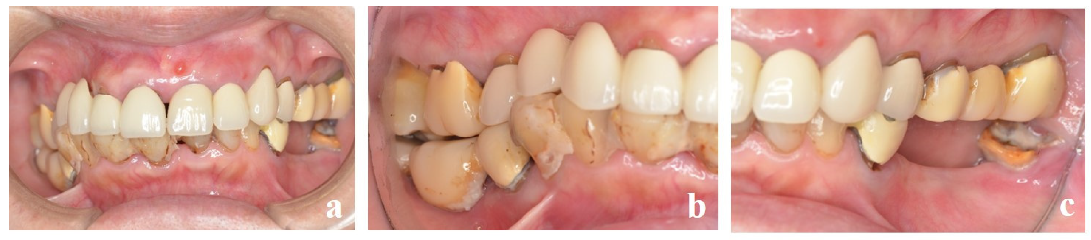
Figure 2.
After comprehensive periodontal treatment, implants were placed in both mandibular molars in a two-stage procedure. Scalloping of the subgingival contour was achieved with a provisional crown at #46. No inflammation of the peri-implant mucosa was observed.
Figure 2.
After comprehensive periodontal treatment, implants were placed in both mandibular molars in a two-stage procedure. Scalloping of the subgingival contour was achieved with a provisional crown at #46. No inflammation of the peri-implant mucosa was observed.
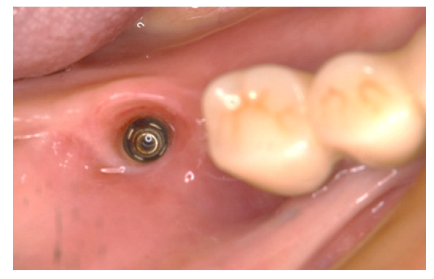
Figure 3.
(a) The dental technician marks the inlay cavity on the semi-sintered crown. (b) Semi-sintered zirconia crown machined from a zirconium oxide disk and cavity preparation before sintering. (c) Sintered crown (main body).
Figure 3.
(a) The dental technician marks the inlay cavity on the semi-sintered crown. (b) Semi-sintered zirconia crown machined from a zirconium oxide disk and cavity preparation before sintering. (c) Sintered crown (main body).
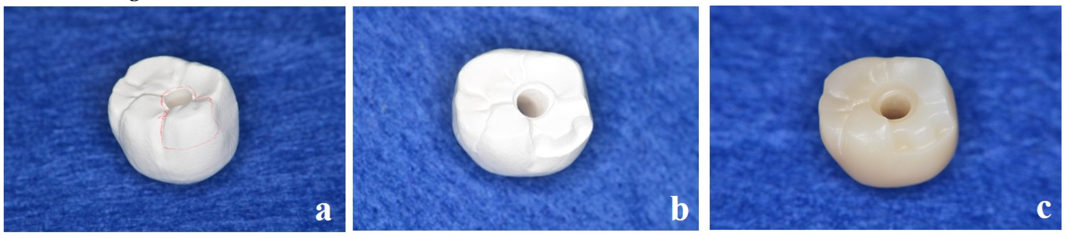
Figure 4.
(a) The inlay cavity in the crown scanned with the laboratory scanner. (b) New inlay body designed with software (Dental System®®, 3Shape, Copenhagen, Denmark). (c) Completed highly translucent partially stabilized zirconia inlay body.
Figure 4.
(a) The inlay cavity in the crown scanned with the laboratory scanner. (b) New inlay body designed with software (Dental System®®, 3Shape, Copenhagen, Denmark). (c) Completed highly translucent partially stabilized zirconia inlay body.
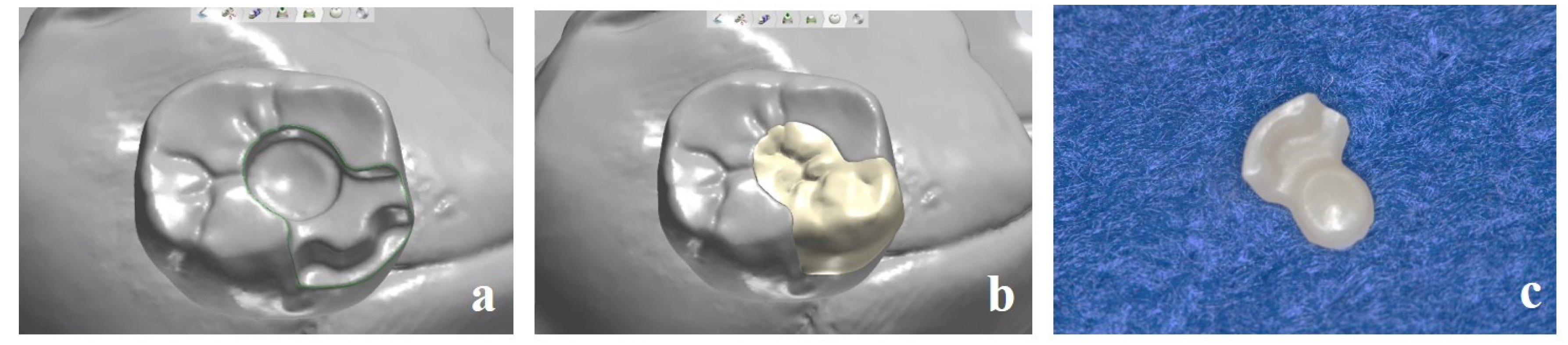
Figure 5.
Completed stained and characterized superstructure.
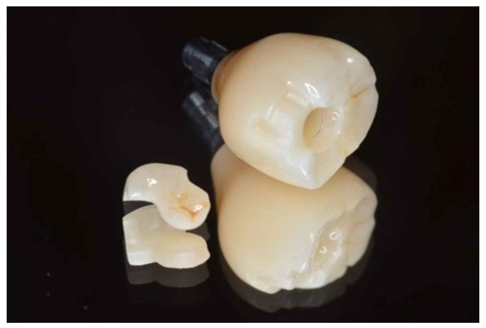
Figure 6.
Excellent esthetics with the superstructure placed after the abutment screw was fastened at 20 N/cm. The removal instrument is hooked into the notch at the bottom of the inlay when access to the abutment screw is required.
Figure 6.
Excellent esthetics with the superstructure placed after the abutment screw was fastened at 20 N/cm. The removal instrument is hooked into the notch at the bottom of the inlay when access to the abutment screw is required.
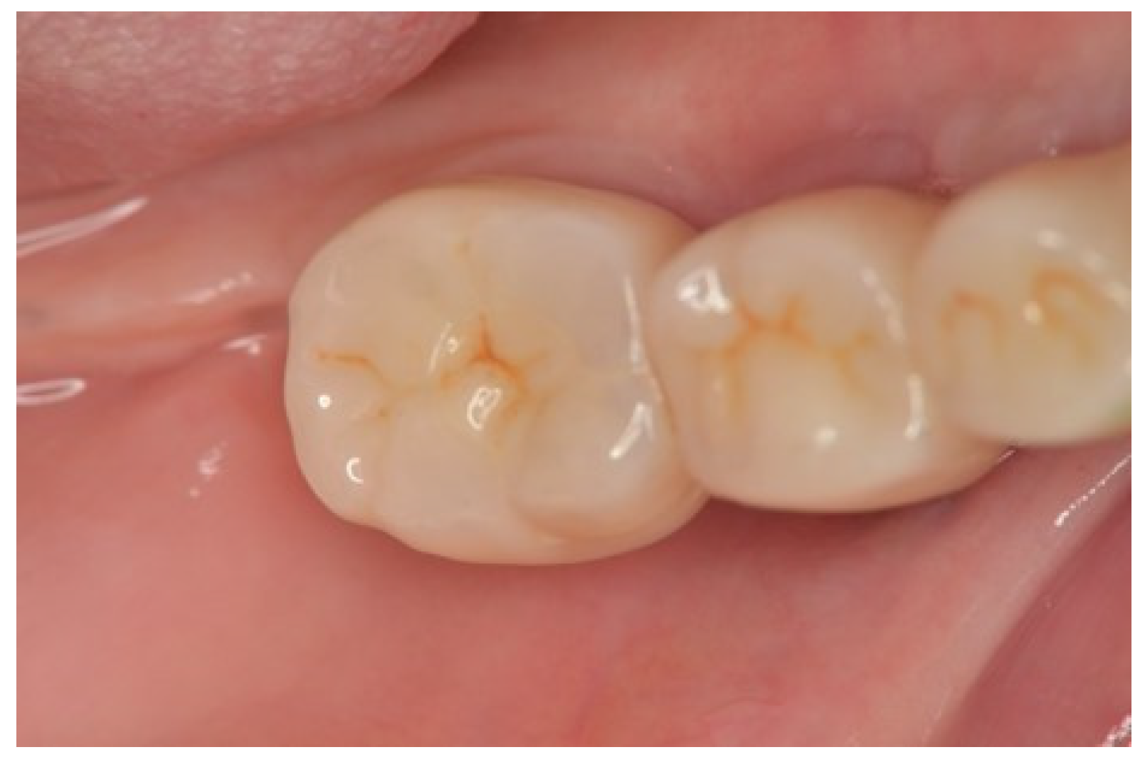
Figure 7.
Superstructure on the left molars (#35, #36) fabricated using the same technique. (a) After sintering. (b) Completed superstructure. (c) High esthetic value was achieved. (d) Occlusal view.
Figure 7.
Superstructure on the left molars (#35, #36) fabricated using the same technique. (a) After sintering. (b) Completed superstructure. (c) High esthetic value was achieved. (d) Occlusal view.
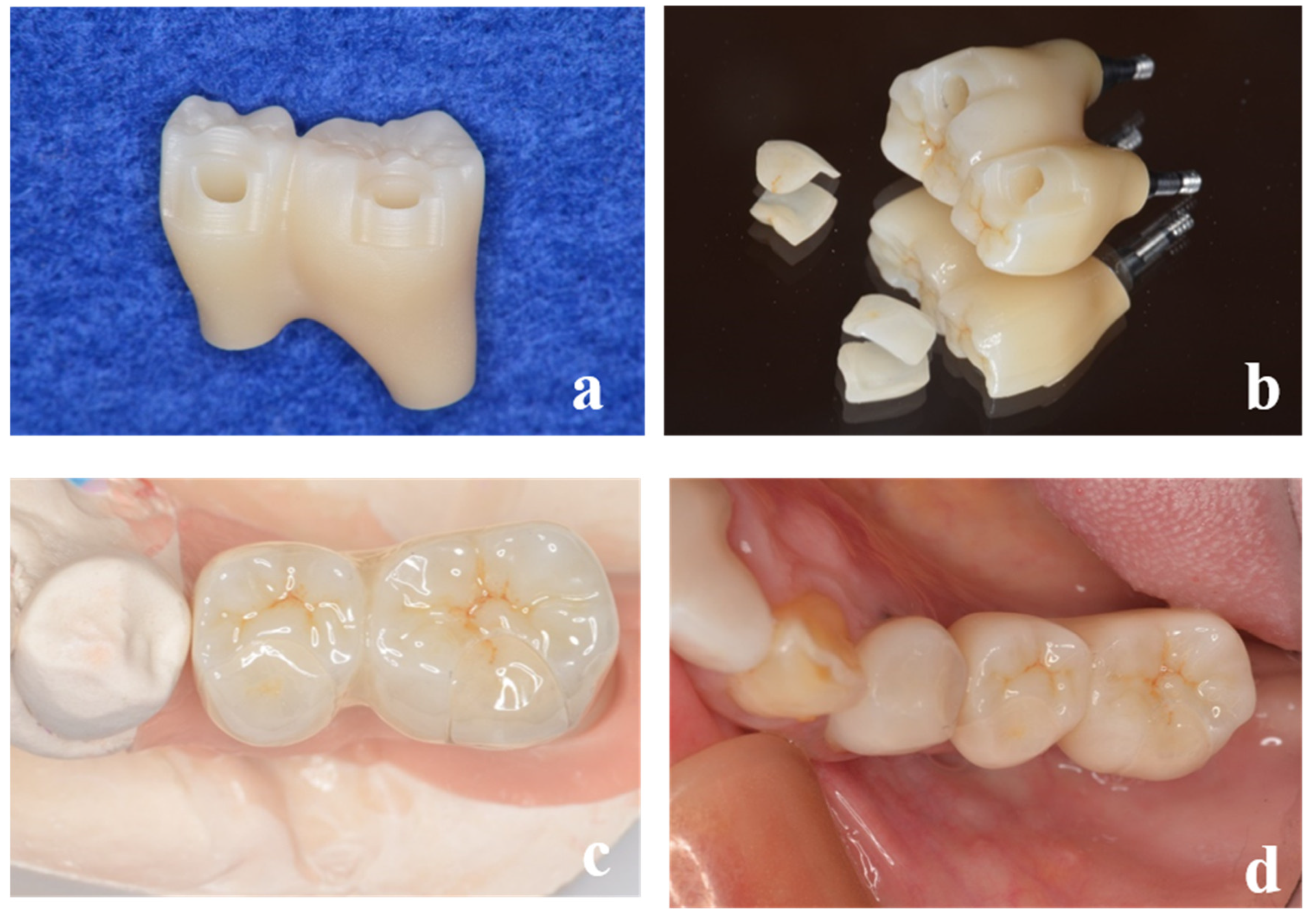
Figure 8.
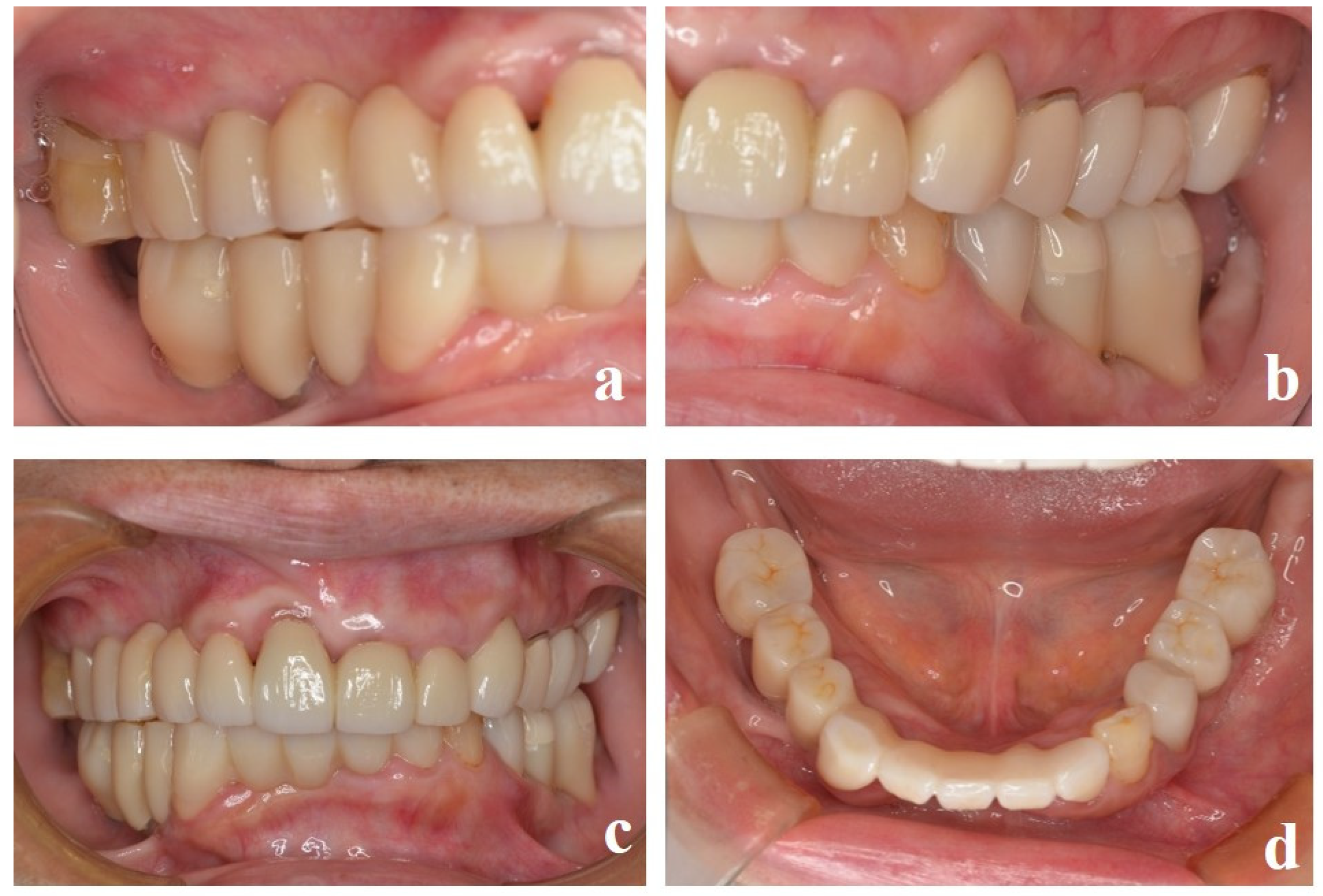
During maintenance treatment. (a) Left lateral view. (b) Frontal view. (c) Right lateral view. (d) Mandibular occlusal view.
Figure 8.
During maintenance treatment. (a) Left lateral view. (b) Frontal view. (c) Right lateral view. (d) Mandibular occlusal view.
Disclaimer/Publisher’s Note: The statements, opinions and data contained in all publications are solely those of the individual author(s) and contributor(s) and not of MDPI and/or the editor(s). MDPI and/or the editor(s) disclaim responsibility for any injury to people or property resulting from any ideas, methods, instructions or products referred to in the content. |
© 2024 by the authors. Licensee MDPI, Basel, Switzerland. This article is an open access article distributed under the terms and conditions of the Creative Commons Attribution (CC BY) license (http://creativecommons.org/licenses/by/4.0/).
Copyright: This open access article is published under a Creative Commons CC BY 4.0 license, which permit the free download, distribution, and reuse, provided that the author and preprint are cited in any reuse.


