1. Introduction
The global effort to reduce carbon emissions has identified road transportation as one of the key contributors to CO2 emissions, as a result EVs have received increased adoption rate to allow a transition to greener energy sources and eliminating tail pipe emissions. The main issues for EVs stem from the use of a battery offering lower driving range (compared to Internal Combustion Engine (ICE) vehicles) and limited availability of charging solutions Some of the main issues facing EVs are the driving range (compared to ICE vehicles) and insufficient charging infrastructure[
1]. DWPT aims to extend driving range by providing continuous charging opportunities which are accessible by multiple users. Wireless charging as a solution offers a better user experience and eliminates interoperability issues [
2]. The stationary requirement placed on conductive charging is no longer present as power transfer no longer requires a physical connection. DWC offers an opportunistic charging approach, where any vehicle can be charged while driving over a DWC coil. Research on compensation topologies, coils design and control have been previously been covered to guide the design process [
3,
4,
5,
6,
7,
8,
9,
10]. Calculating the mutual inductance between coils depends on position, orientation shape and size of the coils [
11,
12,
13,
14,
15,
16,
17,
18,
19].
With short high power energy bursts, the grid connections require more research to better understand the impact of adopting DWC. Further investigating the effects with larger adoption rates would require more simulation analysis, which becomes a computational issue as each set of coils runs at 85kHz. While a detailed simulation might be necessary to run for design and control purposes, this is less necessary for grid interaction studies, as such these more complicated systems are summarised by load profiles which aim to give a general idea of behaviour based on power consumption [
20,
21,
22,
23,
24,
25]. From these load profiles high level observations can be made as a first step, in order to gain a better understanding of the interaction and explore possible control strategies, as a load profile speaks only to the power consumption based over time which is not necessarily specific to the DWC system.
There are different ways to both design and control WPT systems depending on load and objectives for the system. Most commonly the series-series compensation is used for it’s power transfer capability while having efficiency independent of coupling factor. For the purpose of grid interaction, dual-sided control is recommended to allow control and ripple reduction of both grid and load current fluctuations [
26,
27]. For system equivalent models a series of equivalent models are used [
28], while the coupling between two coils has previously been discussed, it remains a property specific to the designed circuit [
11], either coupling factor or mutual inductance can be used. Updating this property achieves dynamic operation of the system. Grid connection studies are typically carried out on IEEE bus systems, for the purpose of this paper a scaled down version is used.
In
Section 2 describes the switching system (and its operation mechanism) which is used was a baseline for the the proposed system in
Section 3 which details the equations used for modelling the simplifying DWC system.
Section 4 presents results of the proposed system and discusses implementation accuracy and speed trade-off.
2. Dynamic Wireless Charging Switching Circuit
2.1. Full Circuit
The basic system required for WPT for EV charging the minimum circuit required consists of an inverter, rectifier and inductive coils and compensation capacitors. Adding primary and secondary DC/DC converters helps improve efficiency and control of the system by decouple both the source and load from fluctuations in the wireless power transfer system.
The base circuit used for comparison in this research is shown in
Figure 1. The sub-circuit function aims to control either the voltage or current at intersection or connection points between subsystems. Primary side DC/DC converter controls the DC bus voltage which is supplied to the inverter; The inverter controls switching frequency for WPT, based on system parameters results in a secondary coil current; controlled rectifier using secondary coil current maintains a reference DC voltage; secondary DC converter can be set to constant current or voltage based on load requirements (for EVs this is based on State-of-Charge (SOC)).
Note: The circuit is designed to be symmetrical around the inductive coils, hence can be configured to run in reverse mode for Vehicle-to-grid (V2G) applications.
2.2. DC/DC Converter
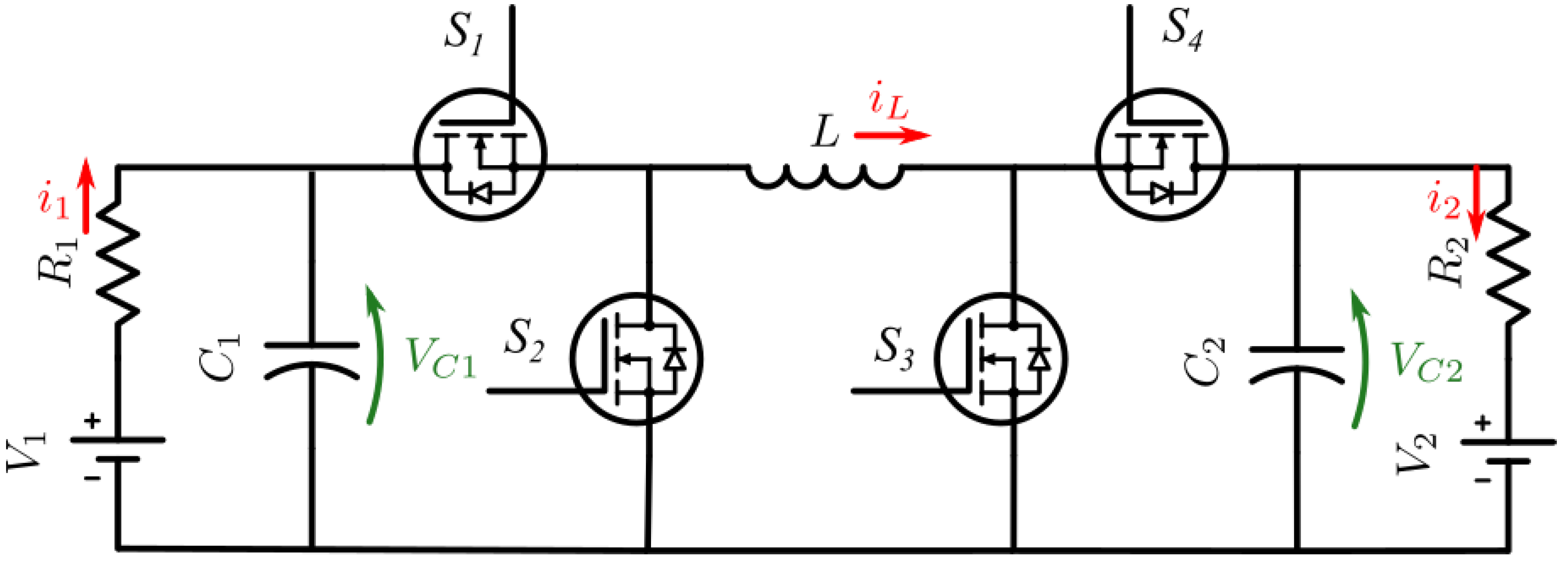
For both primary and secondary side of the circuit in
Figure 1, a configurable bidirectional DC/DC converter is used. Based on the used of switches S1-S4, the converter can set to Buck, Buck-Boost or Boost mode in either forward or reverse direction, the possible configurations are shown in
Table 1, where a PWM signal is used to track a reference signal using a PI controller.
Figure 2.
Configurable bidirectional DC/DC converter.
Figure 2.
Configurable bidirectional DC/DC converter.
2.3. Inverter
A fixed duty cycle inverter is used to drive the WPT circuit at resonant frequency.
Figure 3 shows a basic implementation where a constant voltage sources and restive load are shown for circuit simplicity, these are later replaced with the circuits shown ins
Figure 1.
2.4. Dynamic Wireless Power Transfer.
The DWPT model, relates the two inductive coils using the induced voltage which is a function of mutual inductance. Same as other mutual inductance systems such as fixed core transformers use the same approach. The mutual inductance is a parameter which describes the link between both primary and secondary sides, the coupling factor is a unit-less constant which describes the same relationship (coupling factor ).
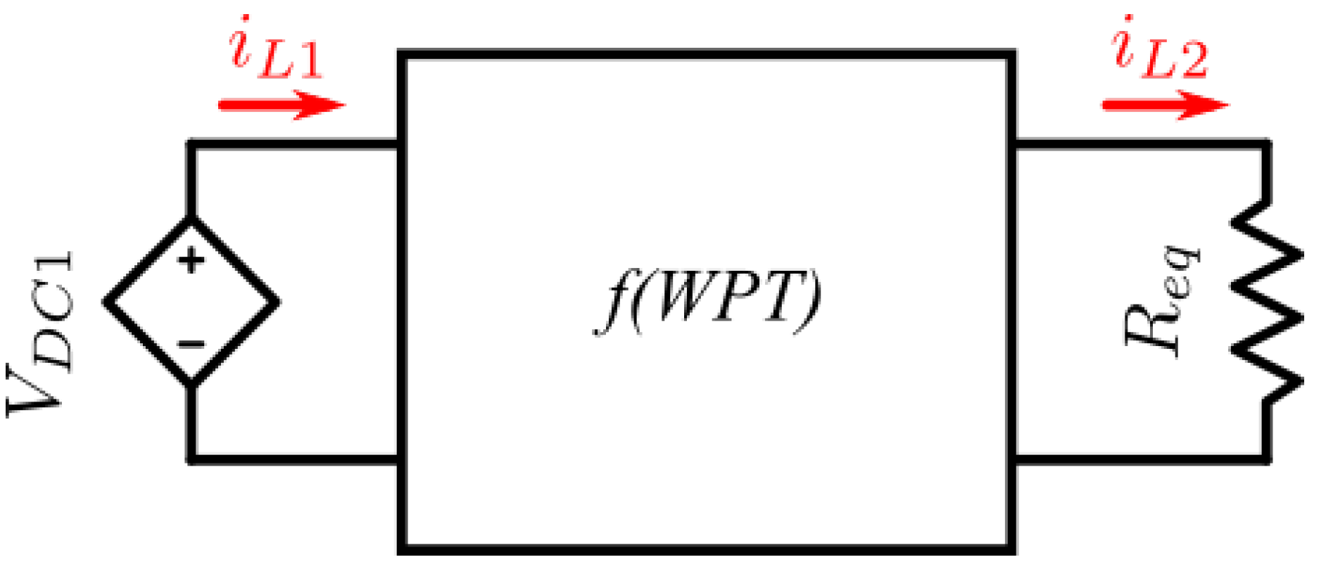
The remainder of the circuit (
Figure 4) uses series-series connected compensation for resonant operation and an equivalent load resistance is used for the diagram. The DWPT model only requires measuring
and
to generate the induced voltages (shown as
and
). Hence the source and load can be connected to the full circuit without changing the DWPT.
Finally, dynamic modelling is achieved by varying the mutual inductance variable. As the mutual inductance is a function of displacement between the two coils, hence changing the mutual inductance will model the dynamic changes in the system. Previous research discusses this in more detail [
26] including the model used for mutual inductance [
11].
2.5. Semi-Controlled Rectifier
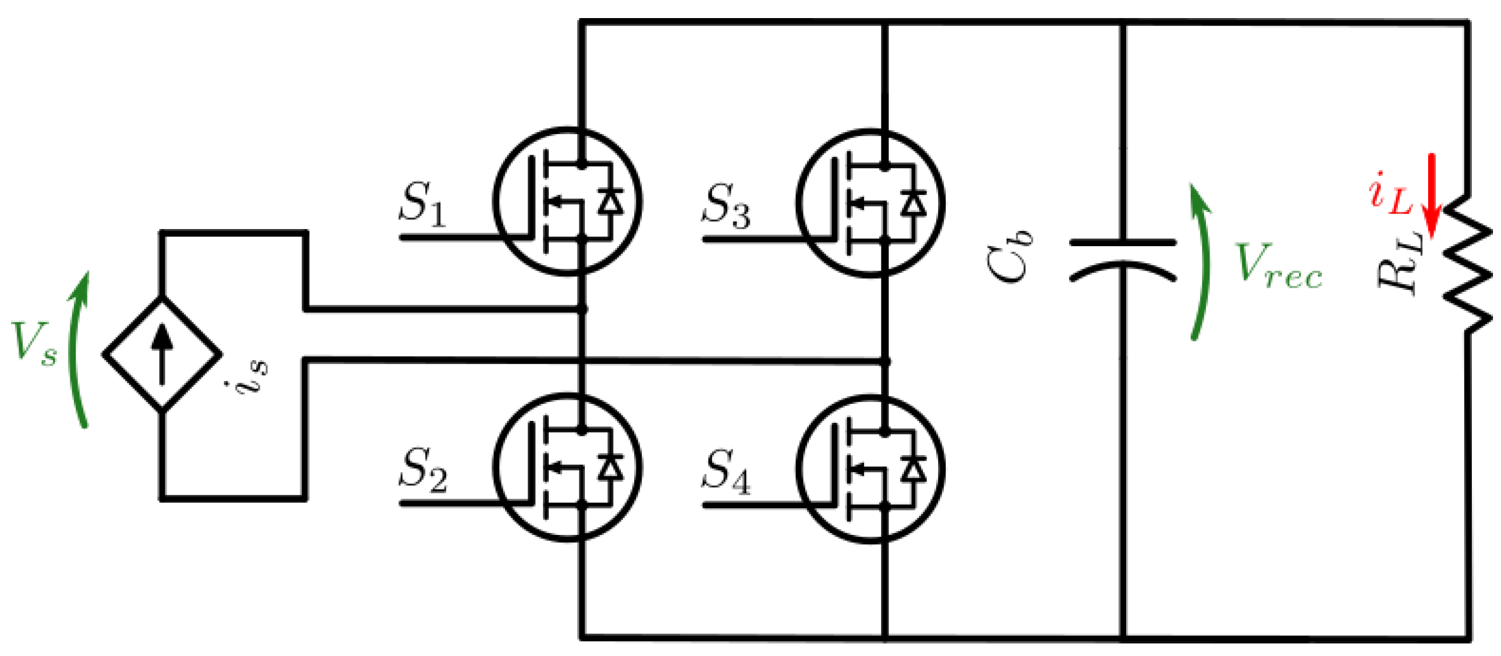
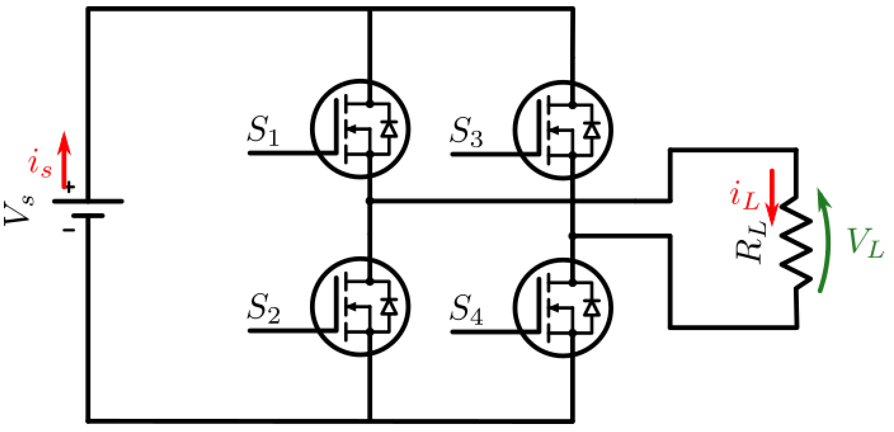
For the function of a semi-active rectifier only switches S2 and S4 are used to control power flow. When S2=S4=0, this functions as a rectifier allowing maximum power flow; when S2=S4=1, a return path is created for the source current, effectively disconnecting the power flow.
The use of this circuit is recommended as secondary DC voltage source can keep rising throughout operation up to an unsafe level. This occurs when the WPT provides more power than is passed to the load, which occurs often when providing constant output characteristics and will also have an impact on output voltage/current ripple. The alternative is to introduce further control into the system where, typically at the primary side, where there is delay in response as secondary DC/DC voltage is decoupled from the primary converters by the WPT circuit. Furthermore the practicality of having primary/secondary side communication can be an issue.
Figure 5.
Semi-controlled rectifier diagram.
Figure 5.
Semi-controlled rectifier diagram.
2.6. System Control
The circuit used in
Figure 1, is designed to have each sub system control variables within it’s circuit using a PI controller for duty cycle which is then used to generate a PWM signal supplied to the switches as described in each sub-circuit section above. Hence, the primary DC/DC converter controls primary DC bus voltage; the inverter is fixed duty cycle (hence uncontrolled); rectifier control secondary DC bus voltage; secondary DC/DC converter controls load charging characteristics (constant current used in this paper).
2.7. Connection of Subsystems and Additional Requirements
The interconnection of subsystems can be a challenge, as ideally these systems would connect directly to each other (similar to the switching circuit). However this is not always possible as each system is designed with ideal sources and loads, hence a solution can be achieved. Once multiple systems are chained together, the MATLAB Simulink solver has issues defining circuit parameters and views the system as a logic loop.
2.7.1. Primary DC/DC Converter
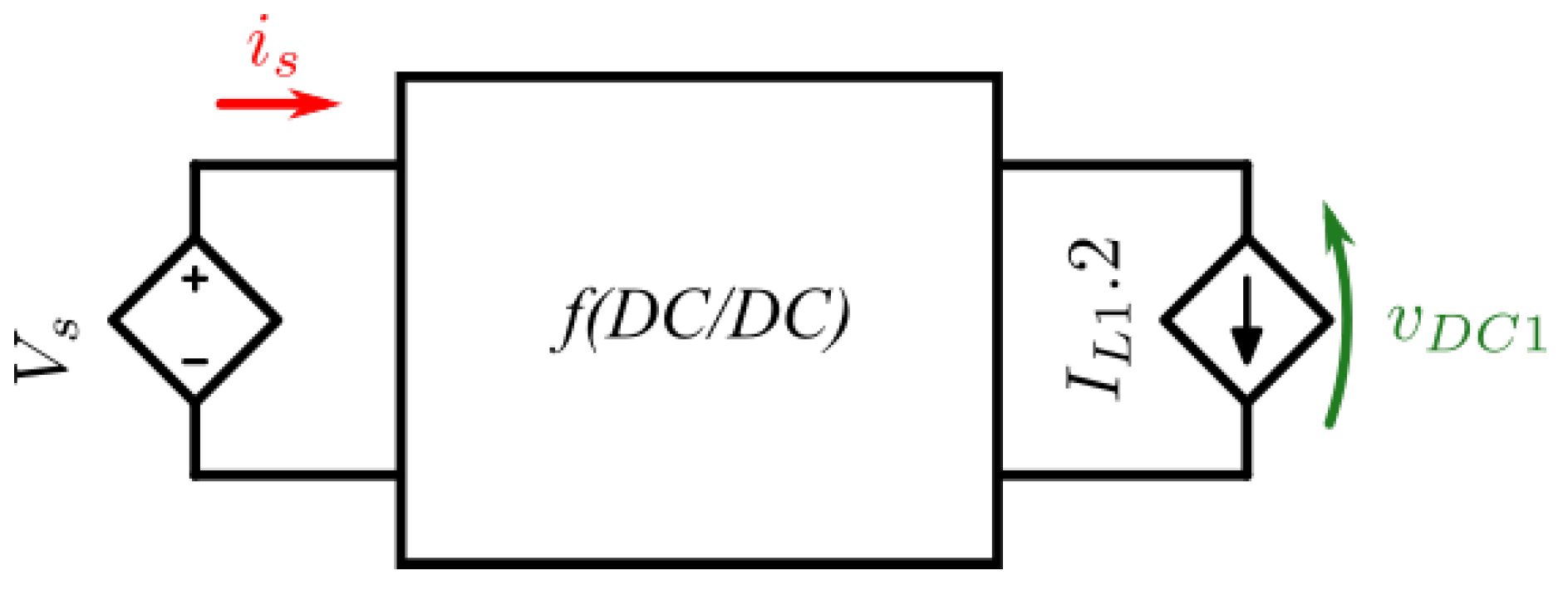
This main consideration for this circuit is the conversion of primary coil current from WPT to the equivilant DC current to be applied to the output of the DC/DC converter. The relationship between the magnitude of primary coil current (
) and primary DC/DC converter output current (
):
Where
is the converter efficiency. This is an approximation assuming converter voltage drop is negligible, the remainder is converting the WPT models value to an RMS value.
2.7.2. Wireless Power Transfer
First, the implementation for WPT assumes a sinusoidal input voltage, as the voltage applied in this study is a square wave the approximate value for input voltage is given by:
This implementation is shown in the appendix and code used as the WPT function.
Next, the implementation uses a small signal approach which has been converted to equivalent impedance. While the equations have preserved, note the scale factor (sf) applied in the code to scale up the state space implementation response time.
Approximating the load resistance (secondary DC/DC converter) is achieved by approximating the converter’s power consumption
Where,
Where
is the duty cycle applied to the semi-active rectifier.
Finally approximating rectifier voltage (
) is done as a function of both the secondary coil current (
) converter equivalent resistance (
) such that:
2.7.3. Secondary DC/DC Converter
Once the considerations above are implemented, the circuit can be used the same as shown in analysis by applying rectifier voltage ().
3. Circuit Equations and Equivalent Circuits
3.1. DC/DC Converter
Figure 2 shows the bidirectional DC/DC converter. To achieve forward operation mode,
leaving S1 as the buck control switch and S3 the boost control switch, allowing the use of buck mode (
), boost mode(
), or buck-boost mode (
). The same is possible for reverse operation mode where
, buck mode (
), boost mode(
), or buck-boost mode (
). Carrying out the circuit analysis gives the following:
3.1.3. Boost Mode - Reverse
3.1.4. Buck Mode - Reverse
3.1.5. Buck-boost Mode - Reverse
3.1.6. Boost Mode - Reverse
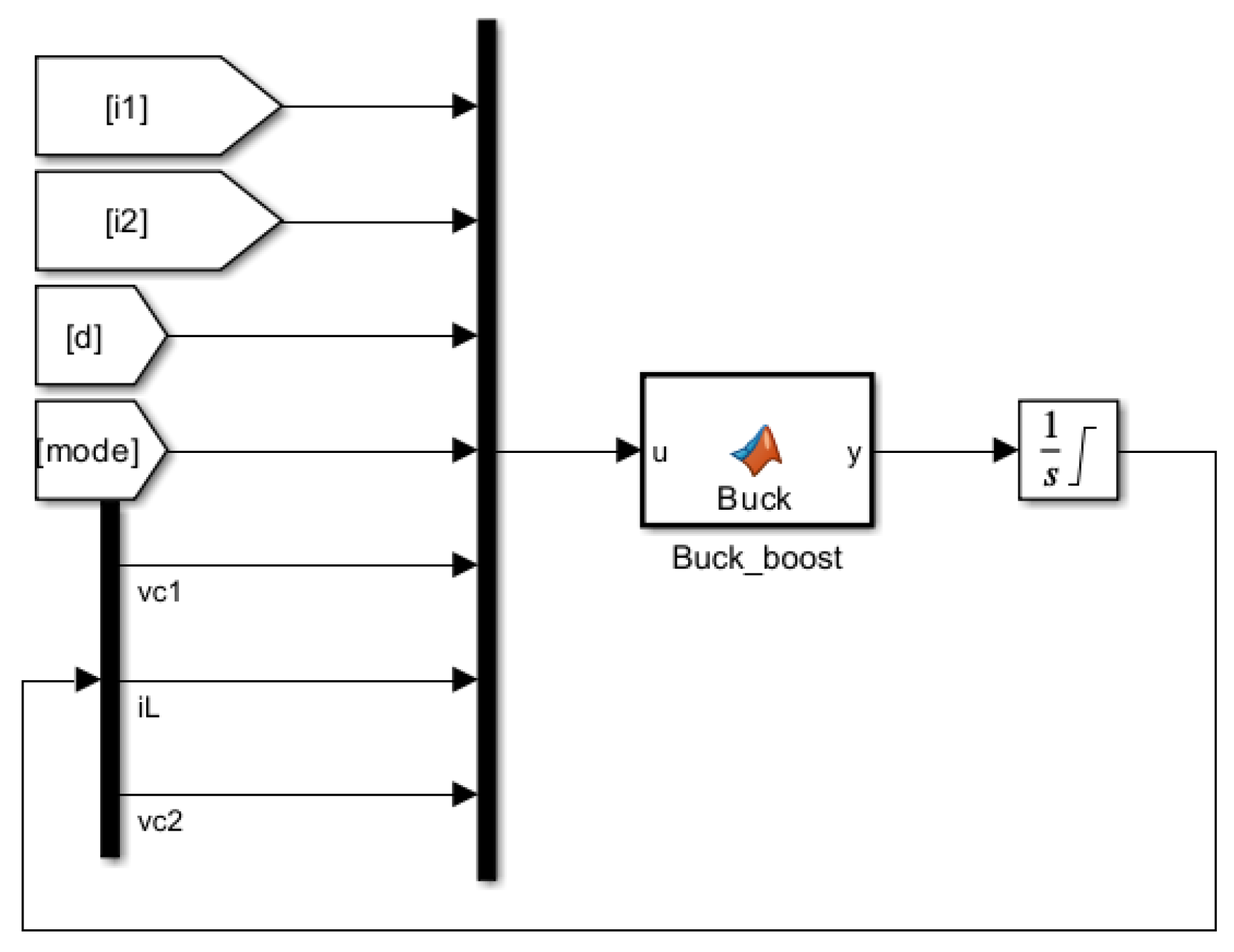
The equivilant model of the DC/DC converter can be seen in
Figure 6 and it’s Simulink implementation in
Figure 7
3.2. Inverter
For the purpose of this research, a fixed duty cycle is used to generate a square wave with amplitude
. The supply voltage/current can hence be related to it’s load voltage/current given by:
A more accurate representation takes into account MOSFET, practically this is <1% difference for analysis. Later this is connected to the WPT estimation which considers sinusoidal input instead of square hence:
3.3. Dynamic Wireless Power Transfer
To replace the WPT circuit, a power estimate from the secondary DC bus is used to estimate load resistance (
), to incorporate the rectifier an equivalent resistance is used to account for the rectified power consumption (
). Like wise for inverter voltage, a sinusoidal input is assumed in AC analysis (
, where f is the operating frequency). The remaining variables represent compensation capacitors C1 and C2, coil inductance L1 and L2 and their resistance R1 and R2, the remaining parameter for mutual inductance links the primary and secondary sides. Note the mutual inductance is calculated from dimensionless parameter of coupling factor (k) where
. With all of the above parameters, a steady state value can be estimated for both the input and output current using the impedance at operating frequency f for all passive components.
Voltage analysis of both sides gives:
Hence the input and output current can be obtained:
For dynamic charging, the steady state values will need to change as system parameters (such as coupling factor changes), hence we are more interested in the peak values of V/I. To achieve this we can use the total impedance of the system for the following differential equations:
Hence we can relate primary and secondary DC buses, based on input voltage and output equivalent resistance. The full circuit features a dual active bridge, where the primary and secondary currents values can be converted to the equivalent DC currents before the inverter and after rectification for i1 and i2 respectively.
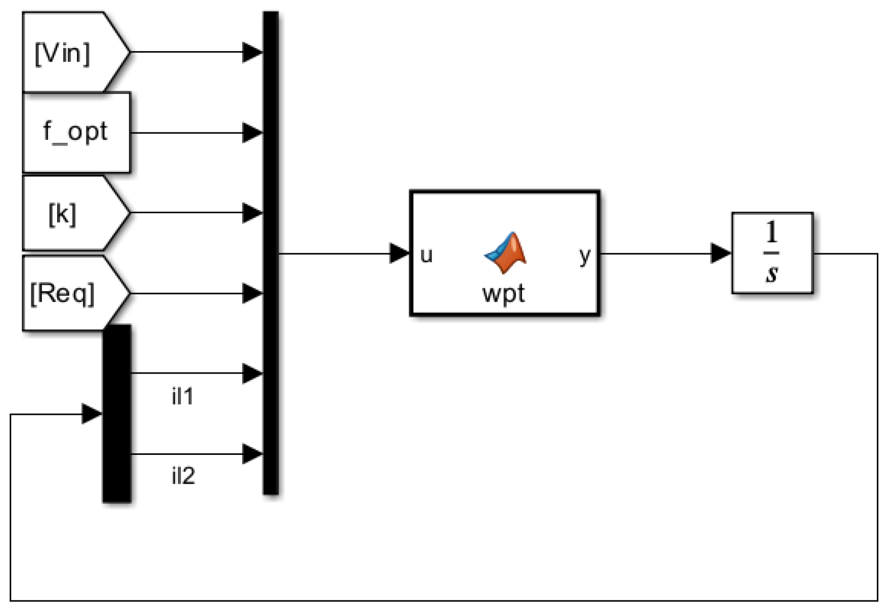
Hence the WPT equivalent circuit implementation is shown in Fig
Figure 8 and
Figure 9 MATLAB Simulink implementation code used to implement the aforementioned equations shown in
annex A and
annex B.
3.4. Semi-Controlled Rectifier
A semi controlled rectifier is used to control rectifier voltage, switching off the input current from the WPT coil. For this function the two MOSFET’s are controlled on to disconnect the power flow to the secondary DC converter.
Analysing the switching behaviour of the controlled rectifier, the voltage before the rectifier is a function of the secondary coil current, rectified voltage and rectifier diode/MOSFET on resitance such that:
The current relationship is given by:
Note, d denotes the duty cycle of the switching signal for the semi-controlled rectifier.
The approximation used for the proposed system is given by:
4. Results and Discussion
4.1. DC/DC Converter
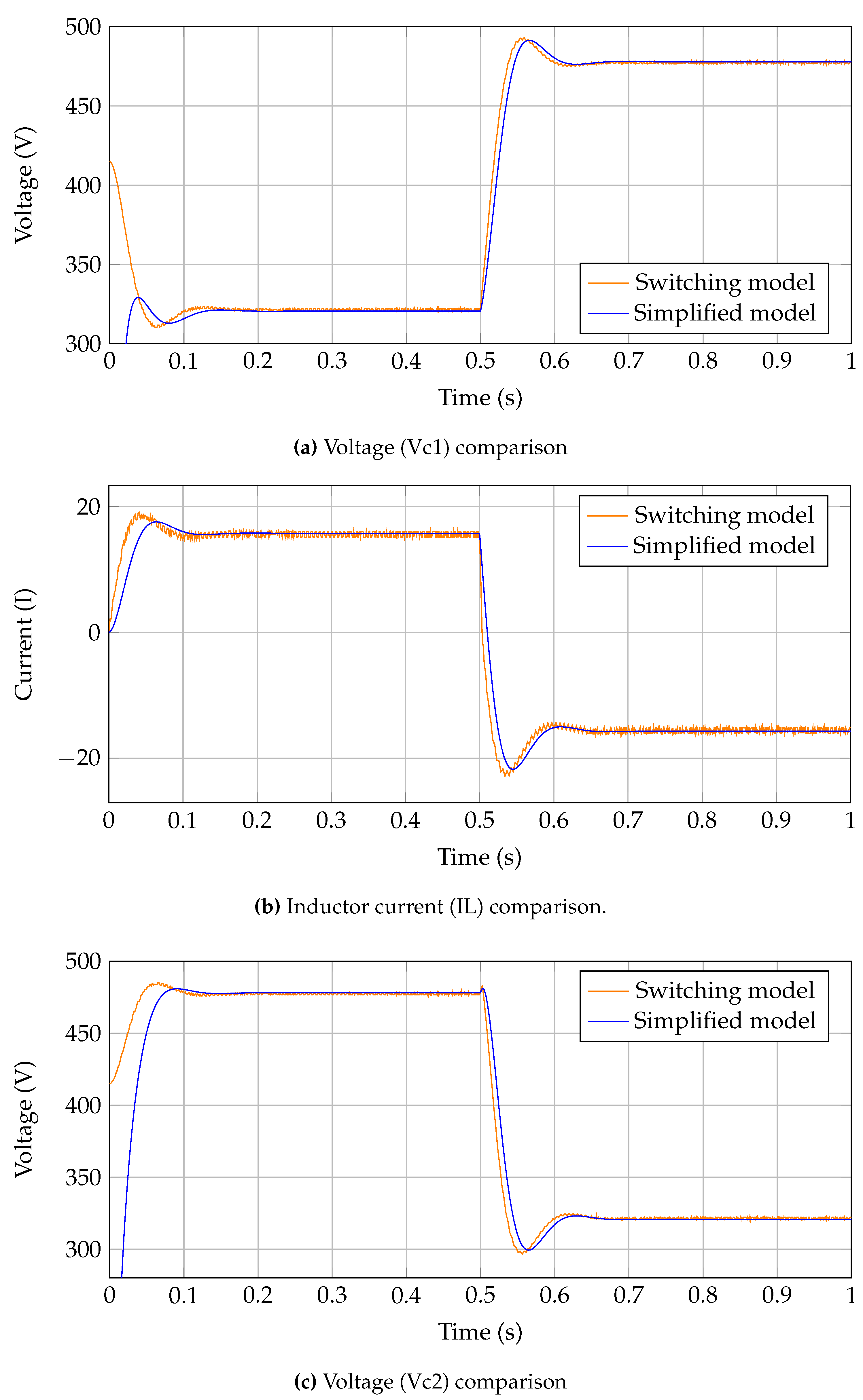
Operation of DC/DC converters is not a novelty, hence the main difference switching direction is of interest. For this reason a change from forward to reverse buck-boost mode is chosen to showcase the direction switching capability. Main working principle is the inductor current switching from positive to negative, to indicate the change of direction in current flow.
The results presented in
Figure 10 show a comparison between the proposed model and switching model, where an accurate representation is achieved.
4.2. Wireless Power Transfer
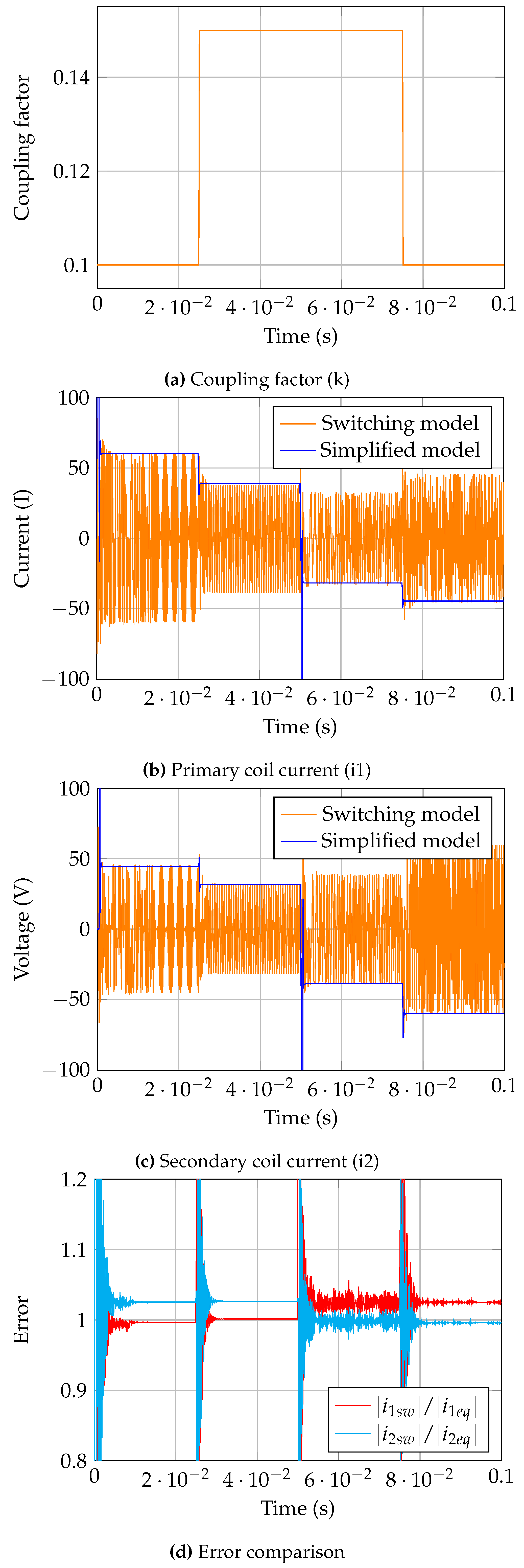
Validation of the proposed WPT equivalent circuit is shown in
Figure 11. First the system operation is shown at steady state with a step change in coupling factor, then the direction of power flow is reversed and the step change is reverted to show the system operating in reverse mode. Notably, the proposed system gives the peak value of primary and secondary currents, which normally remain 0, here however the magnitude is given as negative, to indicated direction of power flow.
4.3. Dynamic Wireless Power Transfer
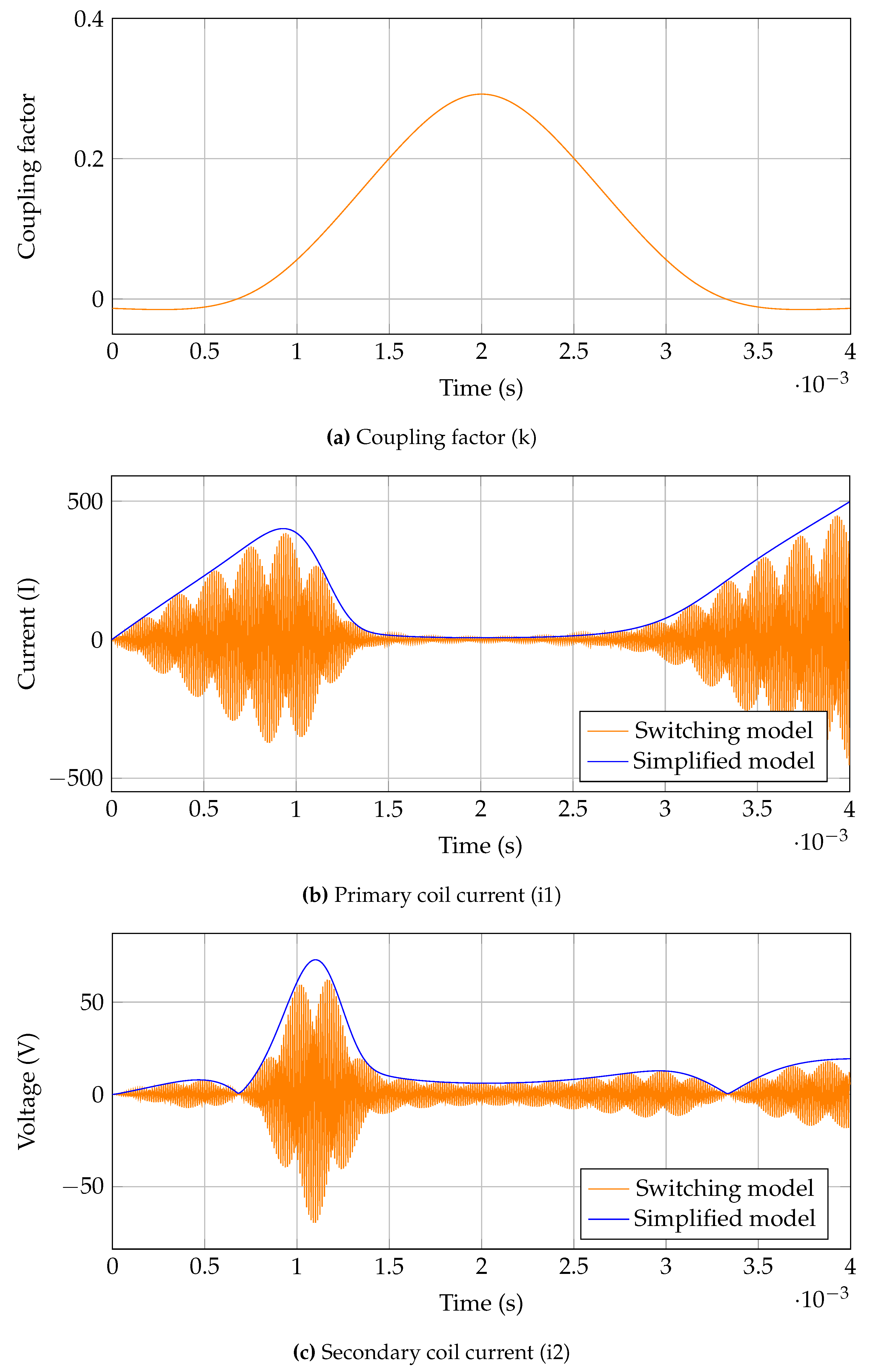
Applying the WPT model to a dynamic scenario,
Figure 12 shows the comparison of primary and secondary coil currents as a function of coupling factor where direction of power flow is switched at 50ms. The proposed system successfully estimates the magnitude of coil current which can than be used to connect to different sub systems (inverter and rectifier) for further analysis.
Table 2.
Simulation system parameters.
Table 2.
Simulation system parameters.
| Parameter |
Symbol(s) |
Value |
| Coil inductance |
L1, L2 |
132.410
|
| Coil internal resistance |
R1, R2 |
1.3m
|
| Compensation capacitance |
C1, C2 |
26.477
|
| DC/DC converter inductance |
Lb |
5mH |
| DC/DC converter capacitance |
Cb |
1.5mF |
| Inverter frequency |
|
85kHz |
| DC/DC converter frequency |
|
2kHz |
4.4. Full System
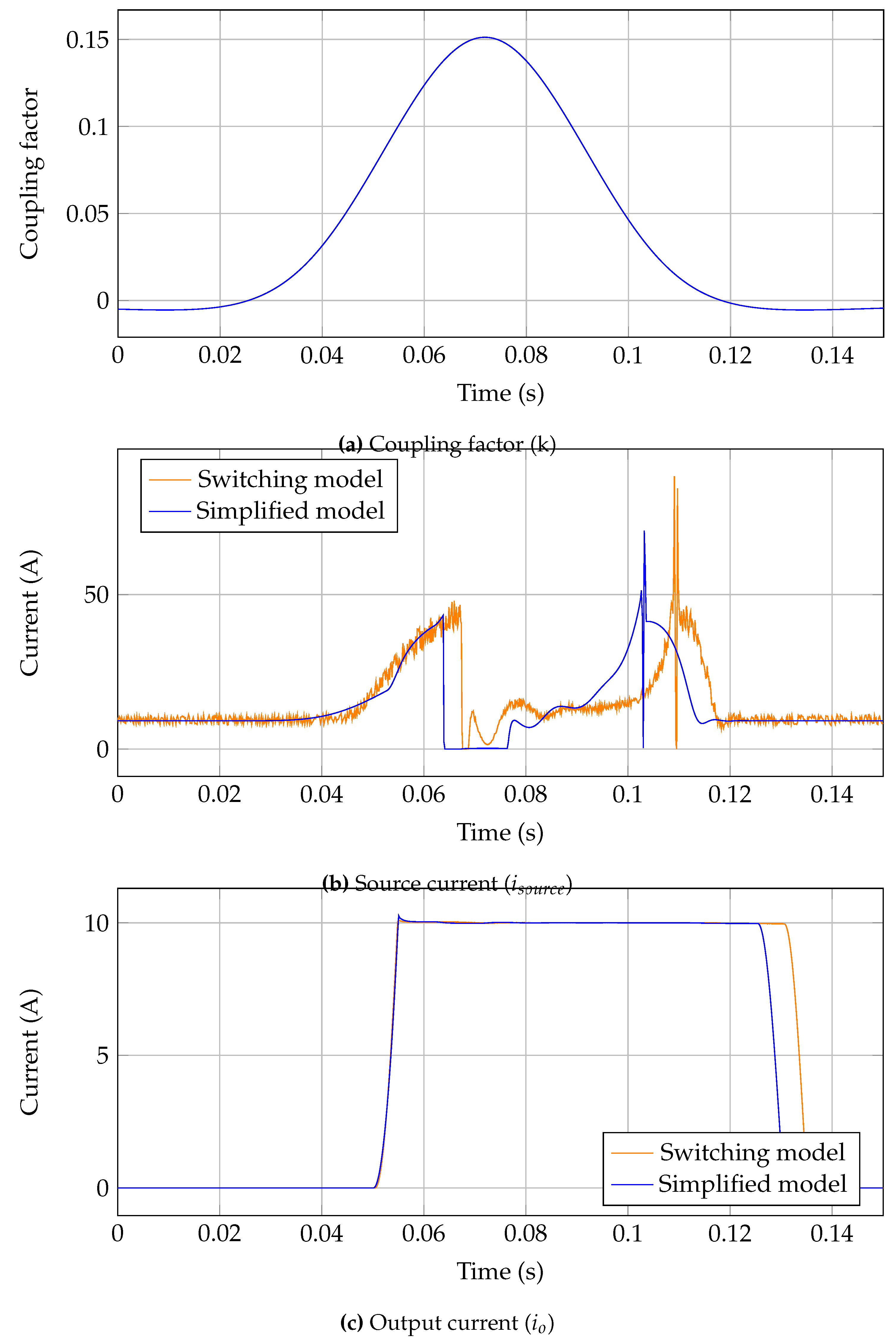
The main point of interest for grid interaction simulations is the input (source) and output currents which are shown in
Figure 13. The results show very similar dynamic response with the main variance being a phase shift in input current. The proposed simulation captures the dynamic behaviour of the system at a much improved simulation time at the cost of a slight time inaccuracy.
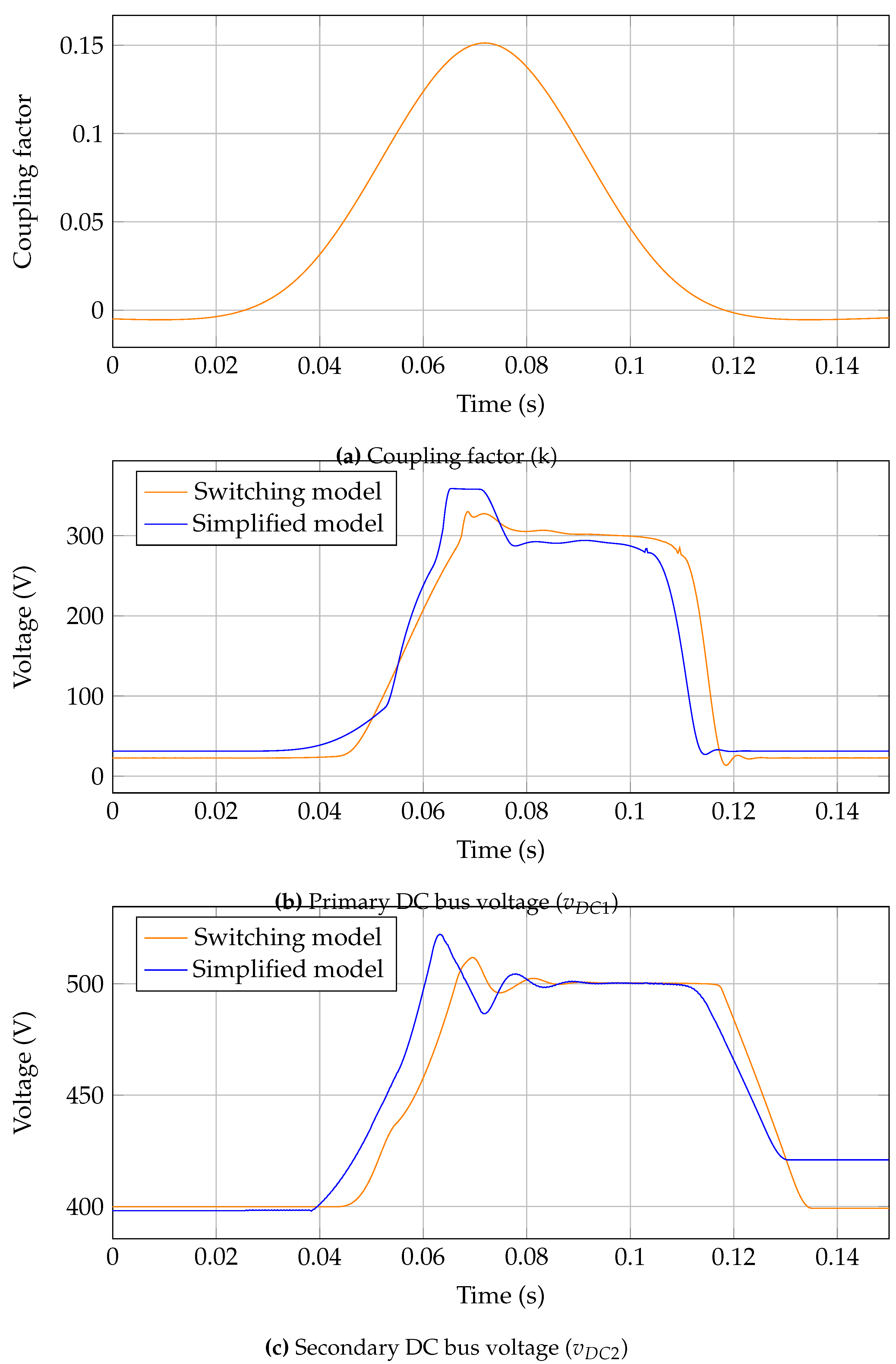
Further exploring the accuracy of the system, the DC bus voltages are shown in
Figure 15, again a similar response is shown, with the main reference voltages being obtained successfully. Notably the secondary DC voltage settles to a higher resting voltage which is due to the simplification of the system not including all internal resistances which would further reduce this value.
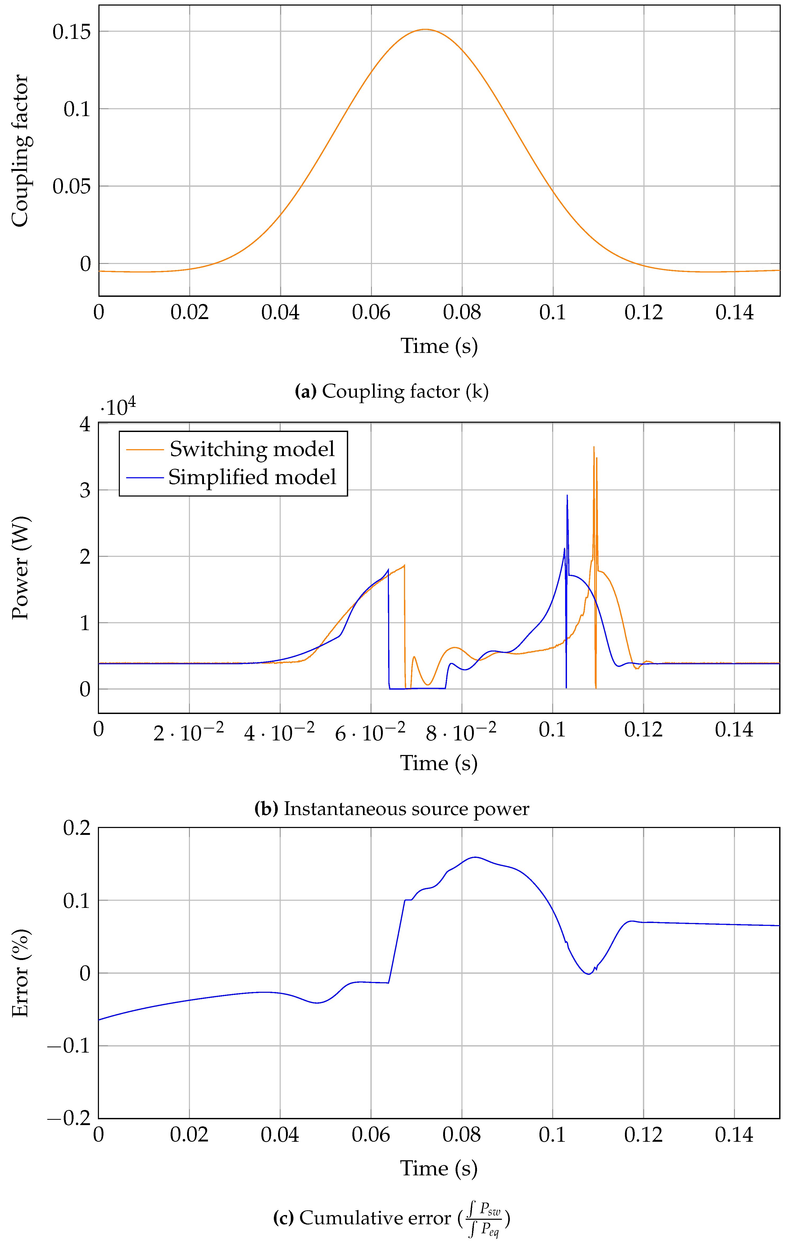
Comparing the energy consumption at the source gives a better estimation of accuracy, as it will settle down to an approximate value after the aforementioned time shift in results.
Figure 14 shows this result, where it can be seen the main working area approximately between 5ms to 12ms, the error is higher due to the shift and lowers again after this period. Hence as a charging event, the proposed system would give an accurate representation of energy consumption with
0ms difference.
Figure 14.
Full system power comparsion and running error estimation.
Figure 14.
Full system power comparsion and running error estimation.
Figure 15.
Full system DC bus voltage comparison in a dynamic scenario.
Figure 15.
Full system DC bus voltage comparison in a dynamic scenario.
4.5. Simulation Time
The system used for simulation has the following specifications: CPU - Intel i7-9700 @3.00GHz; Memory - 16GB RAM; OS - Windows 11 64-bit (10.0 Build); Matlab - R2023a.
Table 3 shows a comparison of the simulation times for each circuit presented. Notably the main simulation showed
4x reduction in simulation time for the same simulation duration, confirming the effectiveness of the simulation techniques in reducing simulation time.
The increased simulation time is due the increased complexity of the full circuit model and computation required to obtain results. This is also true for the proposed equivalent circuit, however instantaneous values for voltage/current are omitted which in turn allows an increase in the required time step to obtain results.
5. Conclusions
The proposed modelling method successfully reduced simulation time for DWPT model, reducing simulation time by a factor of 30. The main circuit for WPT showed a speed improvement by a factor of 17 while maintaining accuracy within 2.5% error which is suitable for the application. Further expansion to a more complex circuit introduced compilations which reduced accuracy, however the modelling techniques used still proved useful in reducing the computation time. The proposed circuit will be able to connect to standard power factor correction circuits or grid connected converters.
6. Future Work
The main issue with the implementation is observed to be the interconnection of subsystems. In fact the issue of this interconnection is subsystem behaviour with low coupling factor (for WPT), this proved to be an issue with the controlled rectifier as at this time the power supplied to the output is approximately zero, meaning it’s resistance is effectively infinite. Hence further study of this interaction would be useful, alternatively expanding the circuit analysis as one whole system instead of separate sub systems is also possible.
Expanding the circuit to accommodate multiple coil systems, both primary and secondary, represents a significant advancement in research, as we move towards including multiple vehicles for charging and integrating multiple transmitter coils. This approach will allow for more comprehensive investigations into practical implementations of DWPT technology. Simulating multiple primary coils with a vehicle traveling between them is a logical next step, as it more accurately reflects future scenarios where road sections are electrified with several transmitter coils. This will also enhance the relevance of grid integration studies.
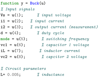
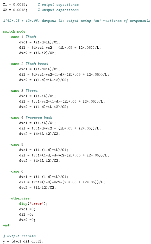
Appendix A. DC/DC Converter Code
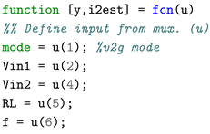
Appendix B. WPT Converter Code
References
- Kumar, M.; Panda, K.P.; Naayagi, R.T.; Thakur, R.; Panda, G. Comprehensive Review of Electric Vehicle Technology and Its Impacts: Detailed Investigation of Charging Infrastructure, Power Management, and Control Techniques. Applied Sciences 2023, 13, 8919. [Google Scholar] [CrossRef]
- Dimitriadou, K.; Rigogiannis, N.; Fountoukidis, S.; Kotarela, F.; Kyritsis, A.; Papanikolaou, N. Current trends in electric vehicle charging infrastructure; opportunities and challenges in wireless charging integration. Energies 2023, 16, 2057. [Google Scholar] [CrossRef]
- Machura, P.; Li, Q. A critical review on wireless charging for electric vehicles. Renewable and Sustainable Energy Reviews 2019, 104, 209–234. [Google Scholar] [CrossRef]
- Mude, K.N.; Aditya, K. Comprehensive review and analysis of two-element resonant compensation topologies for wireless inductive power transfer systems. Chinese Journal of Electrical Engineering 2019, 5, 14–31. [Google Scholar] [CrossRef]
- Miller, J.M.; Jones, P.; Li, J.M.; Onar, O.C. ORNL Experience and Challenges Facing Dynamic Wireless Power Charging of EV’s. IEEE Circuits and Systems Magazine 2015, 15, 40–53. [Google Scholar] [CrossRef]
- Mou, X.; Gladwin, D.T.; Zhao, R.; Sun, H. Survey on magnetic resonant coupling wireless power transfer technology for electric vehicle charging. IET Power Electronics 2019, 12, 3005–3020. [https://ietresearch.onlinelibrary.wiley.com/doi/pdf/10.1049/iet-pel.2019.0529]. [CrossRef]
- Song, K.; Koh, K.E.; Zhu, C.; Jiang, J.; Wang, C.; Huang, X. A Review of Dynamic Wireless Power Transfer for In-Motion Electric Vehicles. In Wireless Power Transfer; Coca, E., Ed.; IntechOpen: Rijeka, 2016; chapter 6. [Google Scholar] [CrossRef]
- Song, B.; Cui, S.; Li, Y.; Zhu, C. A Narrow-Rail Three-Phase Magnetic Coupler With Uniform Output Power for EV Dynamic Wireless Charging. IEEE Transactions on Industrial Electronics 2021, 68, 6456–6469. [Google Scholar] [CrossRef]
- Park, C.; Lee, S.; Jeong, S.Y.; Cho, G.H.; Rim, C.T. Uniform Power I-Type Inductive Power Transfer System With DQ-Power Supply Rails for On-Line Electric Vehicles. IEEE Transactions on Power Electronics 2015, 30, 6446–6455. [Google Scholar] [CrossRef]
- Song, S.; Zhang, Q.; He, Z.; Li, H.; Zhang, X. Uniform Power Dynamic Wireless Charging System With I-Type Power Supply Rail and DQ-Phase-Receiver Employing Receiver-Side Control. IEEE Transactions on Power Electronics 2020, 35, 11205–11212. [Google Scholar] [CrossRef]
- Sallan, J.; Villa, J.L.; Llombart, A.; Sanz, J.F. Optimal Design of ICPT Systems Applied to Electric Vehicle Battery Charge. IEEE Transactions on Industrial Electronics 2009, 56, 2140–2149. [Google Scholar] [CrossRef]
- Zhang, X.; Meng, H.; Wei, B.; Wang, S.; Yang, Q. Mutual inductance calculation for coils with misalignment in wireless power transfer. The Journal of Engineering 2019, 2019, 1041–1044. [https://ietresearch.onlinelibrary.wiley.com/doi/pdf/10.1049/joe.2018.8670]. [CrossRef]
- Su, Y.P.; Liu, X.; Hui, S.Y.R. Mutual Inductance Calculation of Movable Planar Coils on Parallel Surfaces. IEEE Transactions on Power Electronics 2009, 24, 1115–1123. [Google Scholar] [CrossRef]
- Cheng, Y.; Shu, Y. A New Analytical Calculation of the Mutual Inductance of the Coaxial Spiral Rectangular Coils. IEEE Transactions on Magnetics 2014, 50, 1–6. [Google Scholar] [CrossRef]
- Li, Z.; Zhang, M. Mutual inductance calculation of circular coils arbitrary positioned with magnetic tiles for wireless power transfer system. IET Power Electronics 2020, 13, 3522–3527. [https://ietresearch.onlinelibrary.wiley.com/doi/pdf/10.1049/iet-pel.2020.0392]. [CrossRef]
- Zhang, X.; Quan, C.; Li, Z. Mutual Inductance Calculation of Circular Coils for an Arbitrary Position With Electromagnetic Shielding in Wireless Power Transfer Systems. IEEE Transactions on Transportation Electrification 2021, 7, 1196–1204. [Google Scholar] [CrossRef]
- Dehui, W.; Fan, Y.; Chao, H.; Fang, C. Method for the calculation of coupling coefficient between two arbitrary-shaped coils. IET Power Electronics 2019, 12, 3936–3941. [https://ietresearch.onlinelibrary.wiley.com/doi/pdf/10.1049/iet-pel.2019.0556]. [CrossRef]
- Nawaz, B. Analytical Calculation of the Coupling Factor for Single and Multi-layered Circular, Square, and Hexagonal Wireless Power Transfer Coils. 2020 IEEE Wireless Power Transfer Conference (WPTC), 2020, pp. 453–459. [CrossRef]
- Mendes Duarte, R.; Klaric Felic, G. Analysis of the Coupling Coefficient in Inductive Energy Transfer Systems. Active and Passive Electronic Components 2014, 2014, 951624. [Google Scholar] [CrossRef]
- Zhang, X.; Yuan, Z.; Yang, Q.; Li, Y.; Zhu, J.; Li, Y. Coil design and efficiency analysis for dynamic wireless charging system for electric vehicles. IEEE Transactions on Magnetics 2016, 52, 1–4. [Google Scholar] [CrossRef]
- Tavakoli, R.; Pantic, Z. Analysis, design, and demonstration of a 25-kW dynamic wireless charging system for roadway electric vehicles. IEEE Journal of Emerging and Selected Topics in Power Electronics 2017, 6, 1378–1393. [Google Scholar] [CrossRef]
- Tan, L.; Zhao, W.; Liu, H.; Li, J.; Huang, X. Design and optimization of ground-side power transmitting coil parameters for EV dynamic wireless charging system. IEEE Access 2020, 8, 74595–74604. [Google Scholar] [CrossRef]
- Cui, S.; Wang, Z.; Han, S.; Zhu, C.; Chan, C. Analysis and design of multiphase receiver with reduction of output fluctuation for EV dynamic wireless charging system. IEEE Transactions on Power Electronics 2018, 34, 4112–4124. [Google Scholar] [CrossRef]
- Bagchi, A.C.; Kamineni, A.; Zane, R.A.; Carlson, R. Review and Comparative Analysis of Topologies and Control Methods in Dynamic Wireless Charging of Electric Vehicles. IEEE Journal of Emerging and Selected Topics in Power Electronics 2021, 9, 4947–4962. [Google Scholar] [CrossRef]
- Tan, L.; Zhao, W.; Ju, M.; Liu, H.; Huang, X. Research on an EV dynamic wireless charging control method adapting to speed change. Energies 2019, 12, 2214. [Google Scholar] [CrossRef]
- Jakubiak, K.; Liang, J.; Cipcigan, L. Modelling of inductive wireless charging for electric vehicles. 2022 IEEE 16th International Conference on Compatibility, Power Electronics, and Power Engineering (CPE-POWERENG). IEEE, 2022, pp. 1–7.
- Jakubiak, K.; Li, C.; Liang, J.; Cipcigan, L. Control & modelling of wireless charging system for electric vehicles and their application in dynamic scenarios. EVI: Charging Ahead (EVI 2023). IET, 2023, Vol. 2023, pp. 7–14.
- Choi, W.K.; Park, C.W.; Lee, K. Circuit analysis of achievable transmission efficiency in an overcoupled region for wireless power transfer systems. IEEE Systems Journal 2017, 12, 3873–3876. [Google Scholar] [CrossRef]
|
Disclaimer/Publisher’s Note: The statements, opinions and data contained in all publications are solely those of the individual author(s) and contributor(s) and not of MDPI and/or the editor(s). MDPI and/or the editor(s) disclaim responsibility for any injury to people or property resulting from any ideas, methods, instructions or products referred to in the content. |
© 2020 by the authors. Licensee MDPI, Basel, Switzerland. This article is an open access article distributed under the terms and conditions of the Creative Commons Attribution (CC BY) license (https://creativecommons.org/licenses/by/4.0/).
