1. Introduction
The slope deflection method is a displacement method introduced by George Maney in 1915 [
1]. It is employed to perform the analysis of statically indeterminate beams and rigid joint frames [
2]. This method is often taught in undergraduate structural analysis courses across universities worldwide. In this traditional method the end moments of each member of the structure are first expressed in terms of the unknown slope (
) and deflection (
) at the joints referred to as ‘Slope-Deflection’ equations (see Equation (1)).
where
,
are the moments (unknown) at support A and B respectively (see
Figure 1,
,
(known) are the fixed end moments at support A and B respectively,
and
are the slopes at support A and B respectively,
is the relative vertical deflection between two ends and
,
and
are the Young’s modulus, moment of inertia and length of the structural member respectively.
The moment equilibrium at each joint is then applied and simultaneous set of equations are obtained. These simultaneous equations are then solved to determine the slopes and deflections at the joints. Consequently, the moments in the structural members are then evaluated. When compared to methods like moment distribution, the main advantage possessed by slope – deflection method is the ease of programing and the wide range applicability for the indeterminate structures [
3].
Since the slope-deflection equations consists of fixed end moments (see Equation (1)), it becomes essential to learn how fixed end moments are obtained for various loading conditions prior to the introduction of the method. Furthermore, the original derivation of the slope-deflection assumes that the ends of the structural member are fixed, and the moment is acting clockwise at both ends. This often leads to two questions, (1) what happens if the structural members are assumed to be simply supported instead of fixed and (2) what if the moment at the left support is considered to be counterclockwise in the derivation.
In this paper, an alternative method of deriving slope-deflection equations is proposed which addresses the above-mentioned questions. The resulting slope-deflection equations are expressed in terms of slopes of the simply supported beam instead of fixed end moments. Numerical examples are provided, and the results are compared to that of the traditional slope-deflection method. Unlike the traditional method, no prior knowledge of fixed end moments is required for the proposed equations.
2. Derivation of Slope-Deflection Equation
In this section the alternative slope-deflection equation is derived. For this purpose, the same assumptions employed in conventional slope-deflection method are considered i.e., only flexural deformations are taken into account and axial and shear deformations are ignored [
4].
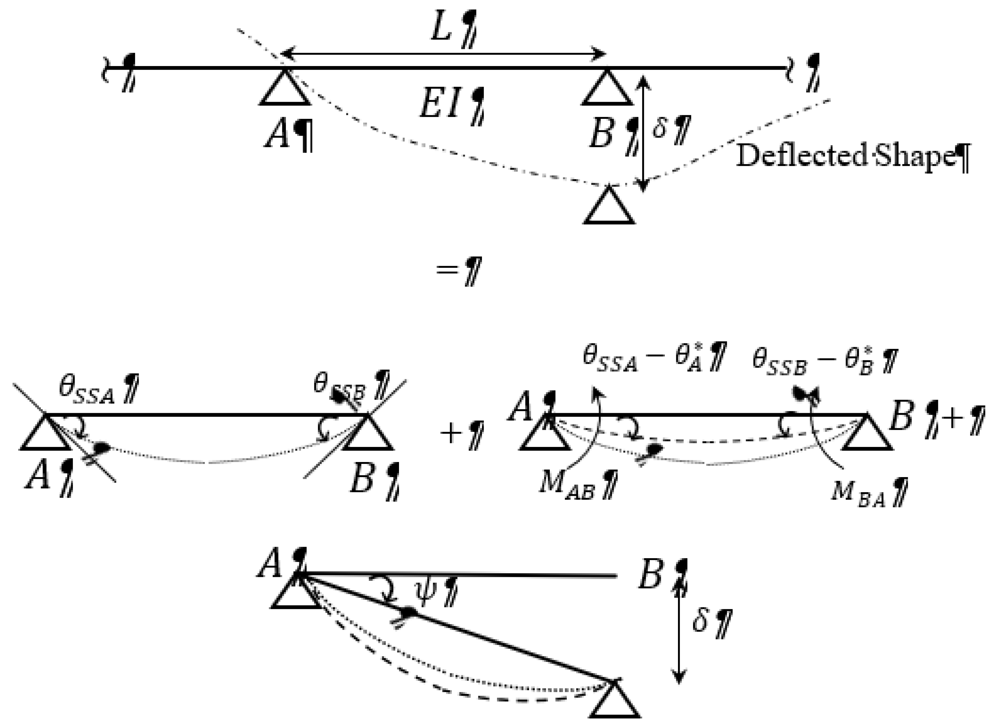
Let
represent any intermediate span of a continuous prismatic beam with length
(see
Figure 1). Unlike conventional Slope-Deflection method, wherein joints A and B are considered fixed, in this alternative approach, beam
is first considered to be simply supported. Let
and
represent the absolute slopes at A and B respectively for the associated loading (see
Figure 1). Since, the moment at joint A and B in a continuous beam are non-zero, two unknown moments
(counterclockwise) and
(clockwise) are applied at joint A and B respectively for a simply supported beam (see
Figure 2).
The resulting slope at A (denoted by
) and B (denoted by
) due to applied moments can then be evaluated using conjugate beam method and principle of superposition [
2].
Let
represent the settlement of support B (see
Figure 1). Consequently, beam
undergoes clockwise rotation
at joint A. The relationship between
and
for small rotation can then be expressed as
The net slope at A (
) and B (
) due to applied moments and settlement of support can then be expressed as
At this juncture it is important to note that overall is positive and overall is negative based on the sign convention that clockwise rotation about a joint is positive and counterclockwise rotation about a joint is negative. In other words, and are not absolute quantities.
Substituting Equation (2) and 3 in Equation (5) and 6,
Solving Equations (7) and (8), the unknown moments
and
can then be expressed as
For the settlement of joint A, the equation Equations (9) and (10) can be modified as
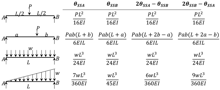
Equations (9)-(12) represents the alternative slope-deflection equations. This equation appears to be same as that of conventional slope-deflection equation except the fixed end moments are replaced by the slopes of simply supported beam (see
Table 1).
3. Numerical Example
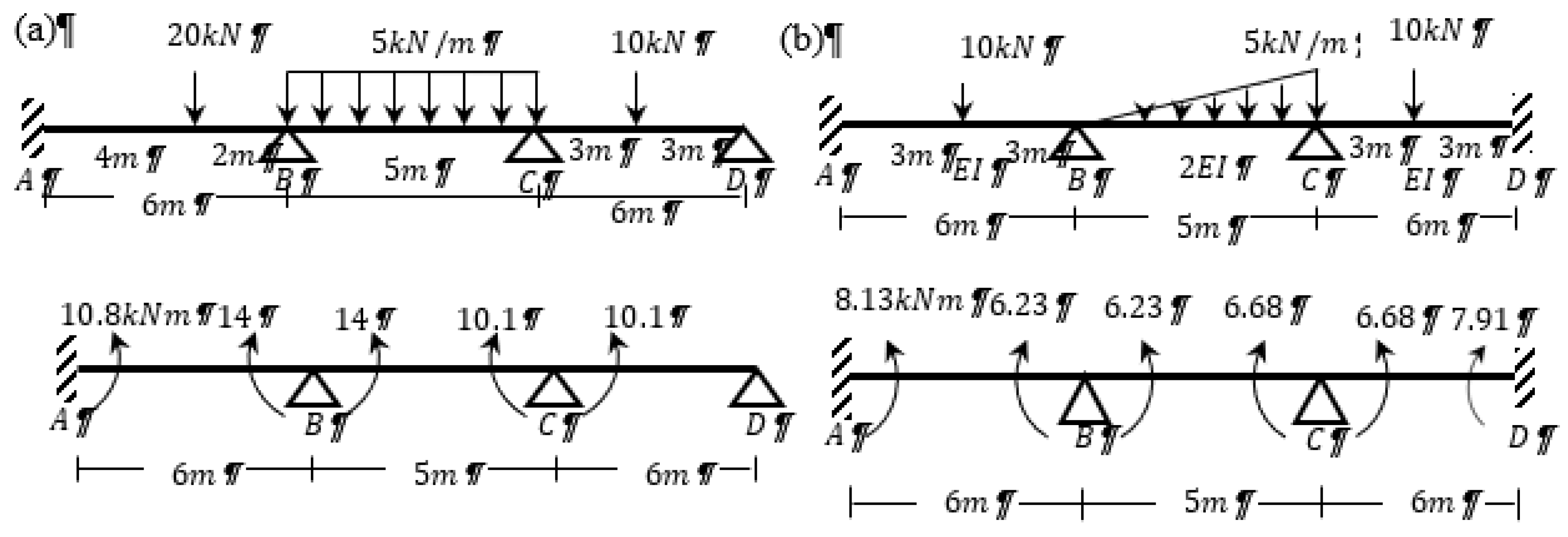
In this section numerical examples are provided to demonstrate the efficacy of the alternative slope-deflection equations. The exactness of the results is compared with the conventional slope-deflection equations (see
Figure 3).
Example 1: Continuous beam with no settlement: Determine the moments at the joints for the continuous beam shown in
Figure 3(a).
| Segment |
|
|
Slope-Deflection Equations |
|
| AB |
|
|
|
(13a)
(13b) |
| BC |
|
|
|
(14a)
(14b) |
| CD |
|
|
|
(15a)
(15b) |
Since A is a fixed end and D is a roller,
and
. Applying equilibrium equation (
) at the joint B (see Equations (13b) and (14a)) and joint C (see Equations (14b) and (15a)),
Solving Eq. 16a, 16b and 16c
Therefore, the moments at each joint (see
Figure 3(a)) are determined to be
Example 2: Continuous beam with sinking of support: Determine the moments at the joints for the continuous beam shown in
Figure 3(a) if joint B sinks downward by 15mm and
.
| Segment |
|
|
Slope-Deflection Equations |
|
| AB |
|
|
|
(19a)
(19b) |
| BC |
|
|
|
(20a)
(20b) |
| CD |
|
|
|
(21a)
(21b) |
Applying equilibrium equation (
) at the joint B (see Eq. 19b and 20a) and joint C (see Equations (20b) and (21a)),
Solving the equations 22a, 22b and 22c
Therefore, the moments at each joint (see
Figure 3(a)) are determined to be
Example 3:
Continuous beam with varying moment of inertia for each span Determine the moments at the joints for the continuous beam shown in
Figure 3(b).
| Segment |
|
|
Slope-Deflection Equations |
|
| AB |
|
|
|
(25a)
(25b) |
| BC |
|
|
|
(26a)
(26b) |
| CD |
|
|
|
(27a)
(27b) |
Applying equilibrium equation (
) at the joint B (see Equations (25b) and (26a)) and joint C (see Equations (26b) and (27a)),
Solving the equations Eq. 28a and 28b
Therefore, the moments at each joint (see
Figure 3(b)) are determined to be
4. Conclusions
Alternative Slope-Deflection equations for indeterminate structures are proposed and the efficacy of the equations for evaluating unknown moments is compared. From this study the following conclusions are drawn.
The results obtained from the proposed approach are exactly same as that of conventional slope-deflection equation.
The proposed approach does not require prior knowledge of fixed end moments. The principle of superposition, conjugate beam method, and slopes of simply supported beam for desired load configuration obtained in the determinate structures are sufficient.
This approach will serve as an alternative explanation for slope-deflection method in the structural analysis class for civil engineering undergraduates.
Funding
This research received no funding.
Data Availability Statement
All data, models, and code generated or used during the study appear in the submitted article.
Conflicts of Interest
All authors declare that they have no conflicts of interest.
References
- Maney G. Studies in Engineering. Minneapolis: 1915.
- Hibbeler RC, Yap KB, Abed F. Structural Analysis. vol. 10th Edition. 2020.
- Abbas M. New Modification for Slope-Deflection Equation in Structural Analysis. International Journal of Engineering and Technical Research 2015:387.
- Kotrasova K, Kormanikova E, Loukili M. Using Software Applications in Teaching of Slope-deflection Method in Subject Static Analysis of Constructions. International Journal of Education and Information Technologies 2021;15:353–63. [CrossRef]
|
Disclaimer/Publisher’s Note: The statements, opinions and data contained in all publications are solely those of the individual author(s) and contributor(s) and not of MDPI and/or the editor(s). MDPI and/or the editor(s) disclaim responsibility for any injury to people or property resulting from any ideas, methods, instructions or products referred to in the content. |
© 2024 by the authors. Licensee MDPI, Basel, Switzerland. This article is an open access article distributed under the terms and conditions of the Creative Commons Attribution (CC BY) license (http://creativecommons.org/licenses/by/4.0/).


