Introduction
Electroencephalography (EEG) is a neuroimaging technique used to record and analyze the electrical activity of the brain. It provides insights into brain function and is employed in various fields, including neuroscience, clinical diagnosis, and cognitive research. EEG measures the fluctuations of electrical potentials generated by neuronal activity through electrodes placed on the scalp. There are two main methods for measuring EEG: invasive and non-invasive. Invasive methods involve implanting electrodes directly into the brain tissue, while non-invasive methods place electrodes on the scalp surface. The choice of electrode type—active or passive—depends on the desired application. Active electrodes include built-in amplifiers for improved signal quality and noise reduction, while passive electrodes are simpler but may require additional amplification.
In recent years, there has been an explosive growth in popularity in the field of brain-computer interface development, resulting in many commercial and open-source brain-computer interfaces being invented. Previously, we developed the ironbci [
18] and PiEEG [
19] device, and in this device, the critical component is the ADC, in particular the ADS1299, and thus the entire BCI device becomes dependent on the presence of this component on the market. As a rule, dry electrodes are used in BCI, which is primarily explained by convenience. At the same time, open-source devices for developing active electrodes were not provided enough.
1. General Theory
Measuring EEG involves recording the electrical activity of the brain through electrodes placed on the scalp. The quality of EEG signals can be affected by various factors, and skin resistance, also known as skin impedance or skin conductance, is one of them.
Figure 1 shows the different types of impedances that occur when measuring EEG signals [
11].
Impedance of skin consisting of several layers. The epidermis and dermis make up the top two layers. The epidermis is the topmost layer of the skin, which has the highest impedance. The impedance range of this skin layer varies from person to person. The second and most complex type of impedance after the skin impedance is the impedance between the skin and electrode. This kind of impedance is the bottleneck in dry electrode design. And its meaning varies depending on the architecture, material, number of pins, and many other parameters. And this moment is an interesting place for our research. The third type of impedance is related to the material and many other parameters of the electrode.
The accuracy of measurement of EEG signals largely depends on the material of the drug, the lower its resistance, the better. Most metals are not suitable, either because they corrode (aluminum, stainless steel (SS)), or because they cause allergic reactions (copper) [
21]. The topic of selecting materials for EEG electrodes is beyond our scope of research, so we will not dwell on this in detail. A review of materials for EEG electrodes, taking into account the magnitude of impedances, was presented by Mihajlović in his study [
12]. But not depending on the type of electrode, both wet and active electrodes are used for EEG (electroencephalography) measurements, but they have different characteristics and applications. Although wet electrodes are easy to use and are suitable for many EEG applications, they are commonly used in laboratory research. Since, their main disadvantage is convenience and the fact that over time there is a change in impedance due to the fact that the gel-conducting cream begins to dry out.
That is why dry electrodes are gaining popularity, especially in the context of using the brain-computer interface [
6]. Dry electrodes are divided into passive and active. Passive electrodes are easy to use and suitable for many EEG applications, however, they can be more susceptible to noise and interference due to their relatively higher impedance and the variability of contact between the electrode and the scalp. Active electrodes are designed to overcome some of the limitations of passive electrodes. They incorporate electronics that actively amplify EEG signals on the scalp before transmitting them to recording equipment. This amplification at the location of the electrodes reduces the effect of cable capacitance and electrode impedance on the skin, resulting in better signal quality and noise reduction. Active electrodes are especially useful when high-quality EEG signals are needed. They can provide more accurate and reliable recordings even under difficult conditions. However, structurally active electrodes are more complex. They require a power source (usually a battery) to operate the amplification circuitry, amplifiers, and other components.
There are several fairly detailed articles in which the authors considered various types of electrodes and compared them both in general [
7,
8] and in more detail, as in [
9] where the authors made a comparison of active and passive amplification electrodes in the same amplifier system. Also previously, we reviewed dry, active, and non-contact electrodes [
2], in many ways, the authors agree that active electrodes are more accurate, so in this paper, we will not dwell on this extensive topic and consider only a few designs close to our version of the prototype.
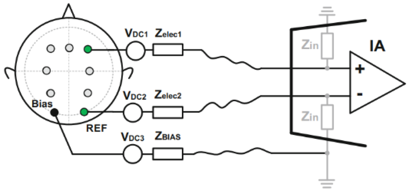
As a rule, the measurement from one active electrode is realized with the help of three connections with a subject—this is the channel itself from which the measurement is taken, the reference from the ted relative to which the voltage and bias are taken is the amplifier channel, in
Figure 2 shows a schematic diagram [
10]. In this case, regardless of the type of electrode and reading device (Digital board)—this scheme will remain constant.
2. Current Stage
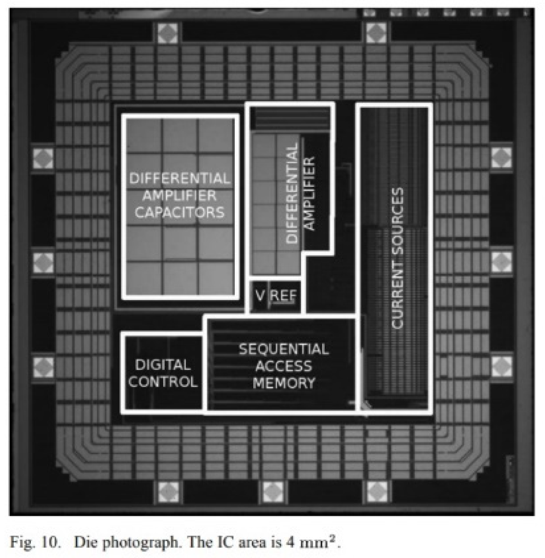
The most promising works are those in which the implementation of analog and digital circuitry is released directly on a chip, which in the end will allow you to create a very compact and high-precision device. Guermandi [
4] presented a CMOS active electrode implementation,
Figure 3. This device, in addition to measuring the EEG, also monitors the impedance of the electrode-skin contact and generates an EIT current to improve the signal quality.
As in Dabbaghian [
5], which presented a integrated circuit (IC) with an active electrode, based on the proposed architecture that improves CMRR, is fabricated using 180-nm CMOS technology.
But progress from these studies can only be felt if these samples are available on the market—but from research to commercialization there is a long way and whether it will be passed.
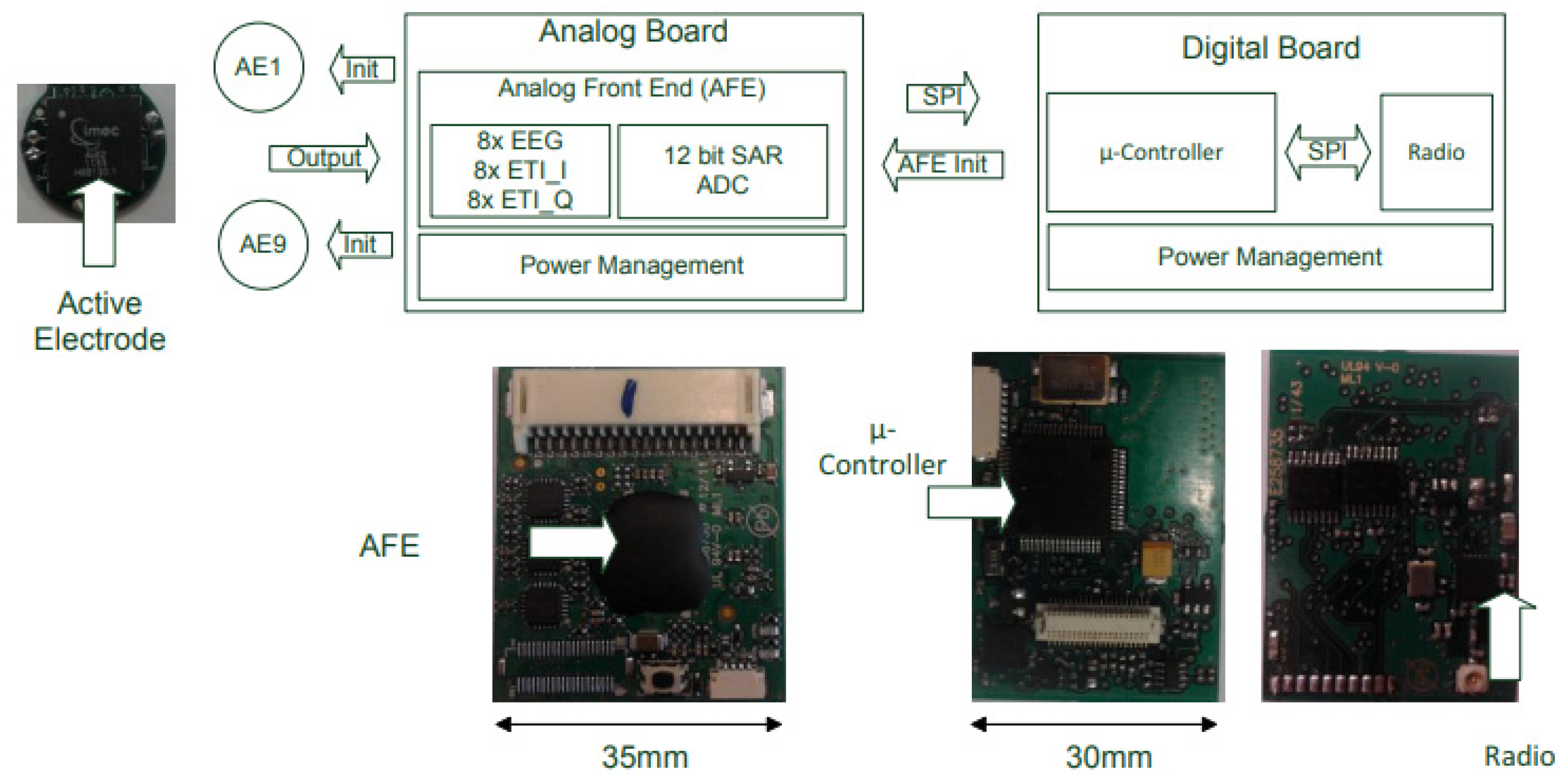
There are several works similar in their subject matter similar to our study. Patki [
13] Presented a miniaturized (<6cm 3) and low noise (60nV/√Hz) wireless EEG sensor node with active electrodes and simultaneous electrode tissue impedance (ETI) monitoring. The positive point of this article is the presence in addition to the analog part and digital, but structurally, the device takes up too much space,
Figure 4.
In the paper [
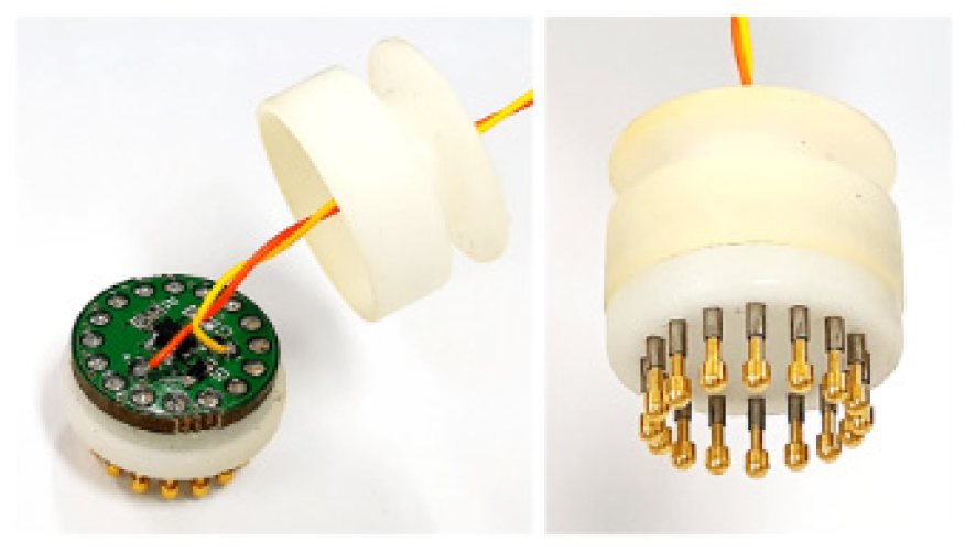
14], Jiang presented a dry active electrode which consists of a soft substrate, an electrode, and a simple circuit with an amplifier and a capacitor,
Figure 5. The soft substrate was made from silicone by molding, and the electrode was made by applying an electrically conductive composite (ECC) to the patterned substrate. The authors also presented a portable biopotential measurement system for working with the developed electrodes. Compared to conventional wet passive Ag/AgCl electrodes for electrocardiogram (ECG) reading, the proposed dry active electrodes showed comparable noise levels and less sensitivity to power line interference and motion artifacts.
Lee [
15], developed a two-wire active dry electrode system by combining finger-shaped spring-loaded probes and active buffer circuits, Fig,6. Heat-shrink probes and a bootstrap-based buffer circuit realized electrical coupling to the scalp surface as well as input impedance conversion along with low input capacitance. Experimental results showed that the proposed electrode is capable of detecting alpha rhythm activation with a low noise level of 1.131 μVrsc and a reduction input capacity by 32.3%.
A prevalent issue observed in the endeavors of other authors who have similarly created the development of active EEG electrodes pertains to of accessible sources. This deficiency not only impedes the practical validation of their findings but also severely curtails the utility of their work for fellow researchers and developers within this specialized field. As such, addressing this limitation becomes imperative to foster more robust and collaborative progress in the realm of active EEG electrode development. Open-source is advantageous for science as it encourages global collaboration, ensures transparency through shared resources, promotes inclusivity by making knowledge freely accessible, accelerates innovation by building on existing solutions, fosters adaptable and customizable tools, engages communities for collective improvement, and offers cost-efficiency by leveraging shared resources. In a world where there is a shortage of chips, chip prices are unstable and so is their availability, so open source devices can simplify access to technologies. Since the availability of open data allows, if necessary, to modernize the circuit according to your own needs, look for replacements for scarce materials, and change technical characteristics to suit your needs.
In this work, the emphasis is on technical details, so the work may be of interest to both scientists and developers.
3. Materials and Methods
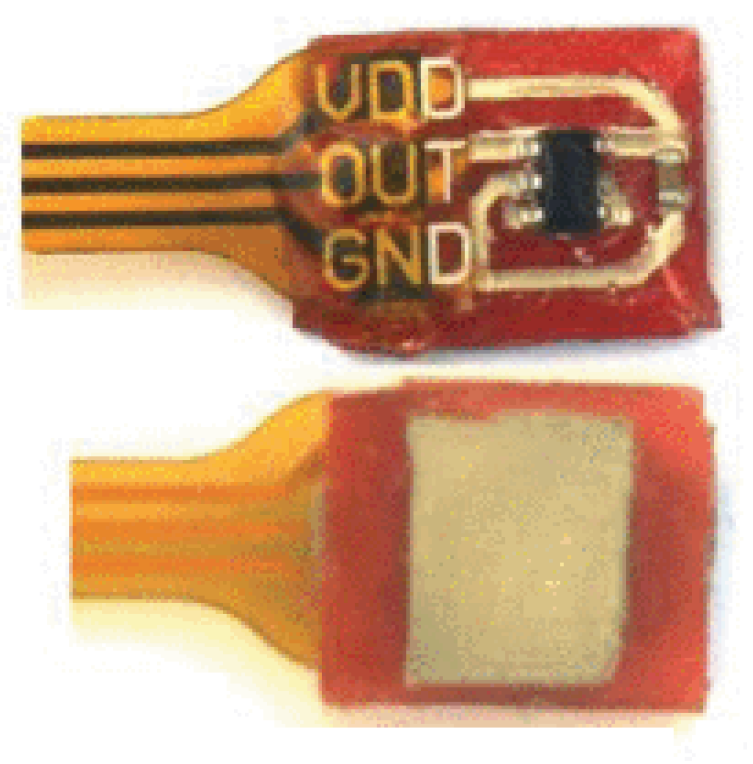
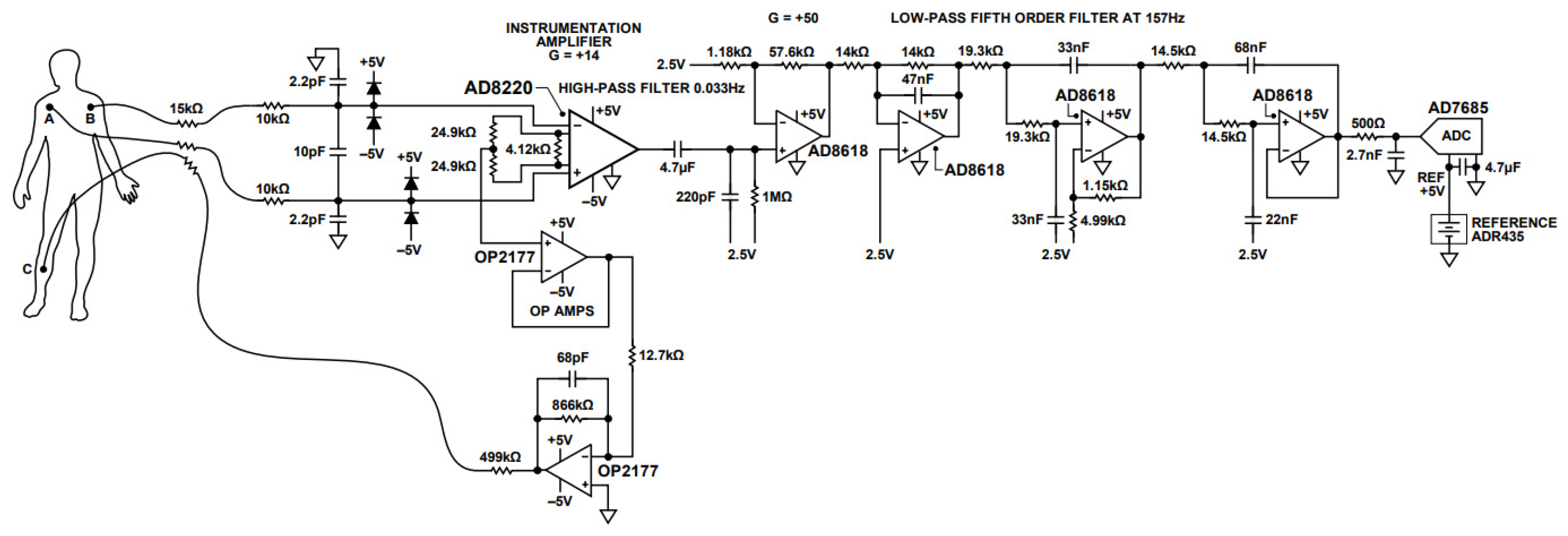
There are a limited number of amplifiers on the market that could be used in a scheme for measuring EEG signals. The EEG signal is very small in nature and is measured in microvolts, so the main requirement for amplifiers is noise, Common-Mode Rejection Ratio (CMRR), Input Impedance. We chose AD8220 from Analog Devices company. The AD8220 is the first single-supply, JFET input instrumentation amplifier available in an MSOP package. the AD8220 has a minimum common-mode rejection ratio (CMRR) of 86 dB at dc and a minimum CMRR of 80 dB at 5 kHz for G = 1. The datasheet for the electrode contains a detailed diagram for measuring ECG signals,
Figure 7. This diagram and this electrode are widely used in ECG detection tasks (16, Li; 17 Capua). What was the inspiration for the implementation of our scheme.
A band-pass filter was implemented on a double-sided single-layer board with a diameter of 18 mm. Initially, the filter parameters were calculated in the Multisim program, then in real time, as a result of long painstaking work, the optimal nominal values for passive components were selected, taking into account the thickness of the board, permeability and other particular parameters.
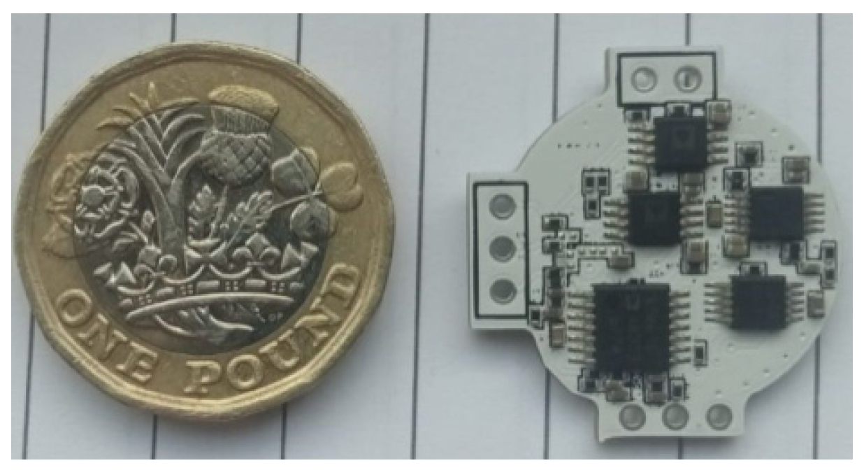
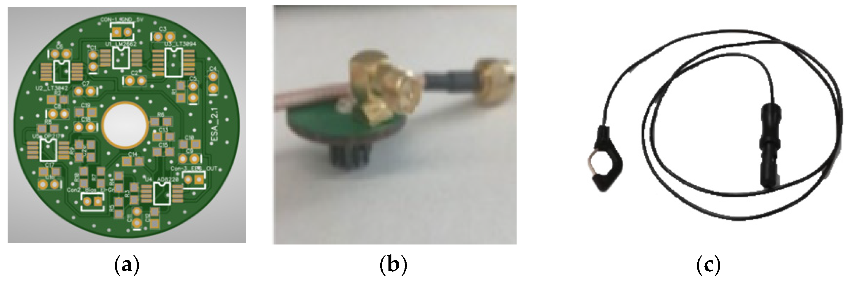
In the same way, the driver right leg circuit was implemented, which currently made it possible to configure the circuit to remove common-mode interference from the EEG signal. The uplifter itself was made in a two-stage mode and tuned through a simulator. The general view of the PCB board presented on the picture,
Figure 8.
To implement the power supply, components with a minimum noise ratio were selected—LT3092, LT3042 from Analogue devices, which have proven themselves to be reliable components in previously our open-source brain-computer interface projects [
3,
18,
19,
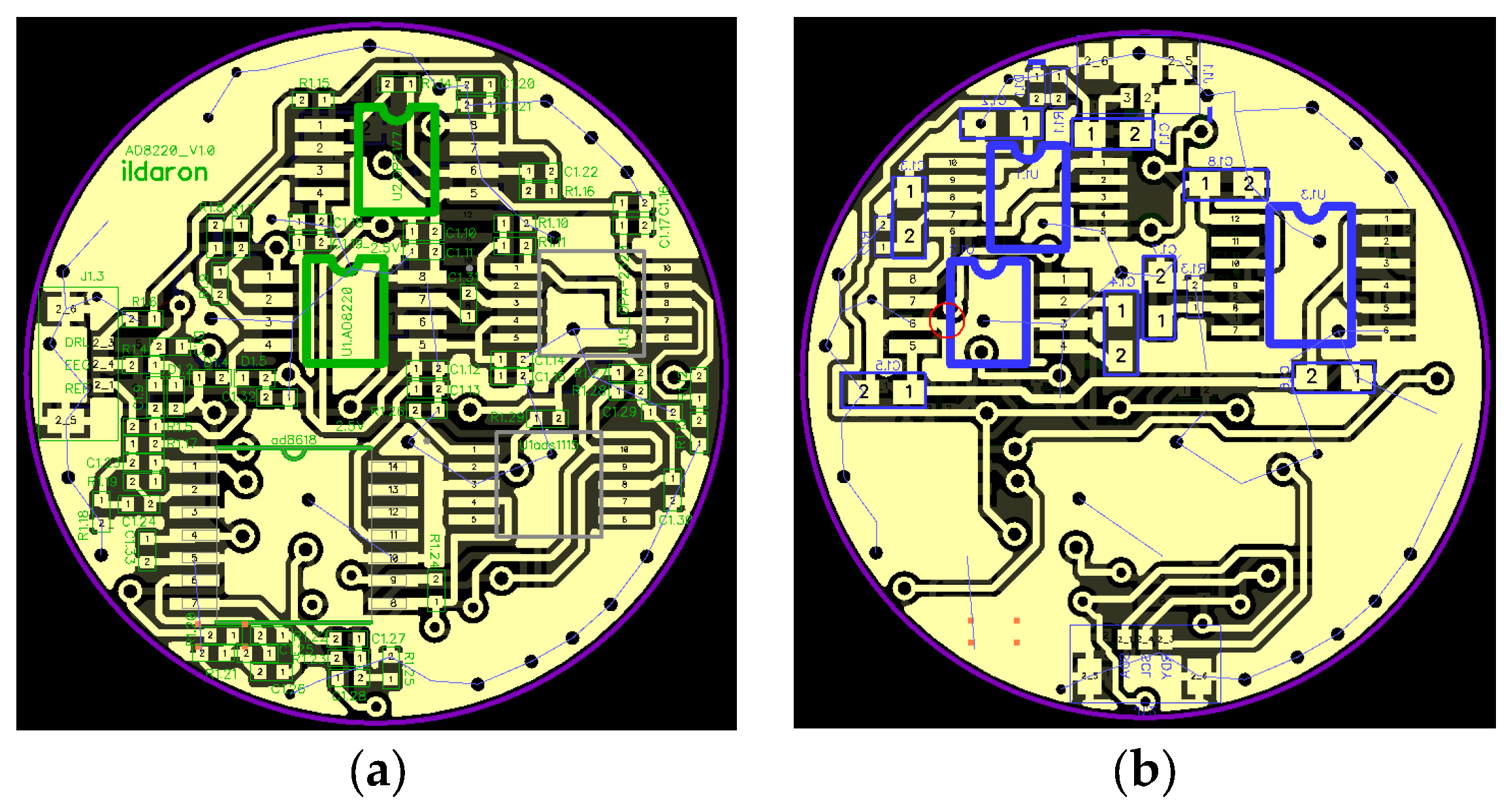
20]. We selected a voltage regulator based on the peak current draw of your BCI system, low output voltage ripple, and low noise. For the ADC, we chose the 16-bit ADS1115. Unlike working with passive electrodes, in our case the ADC is not a critical component and we were guided by the convenient data transfer protocol (SPI), data transfer speed, size, and power consumption. On
Figure 9 showed an image of a PCB board implemented in the DipTrace program (
https://diptrace.com/ available 31.08.2023).
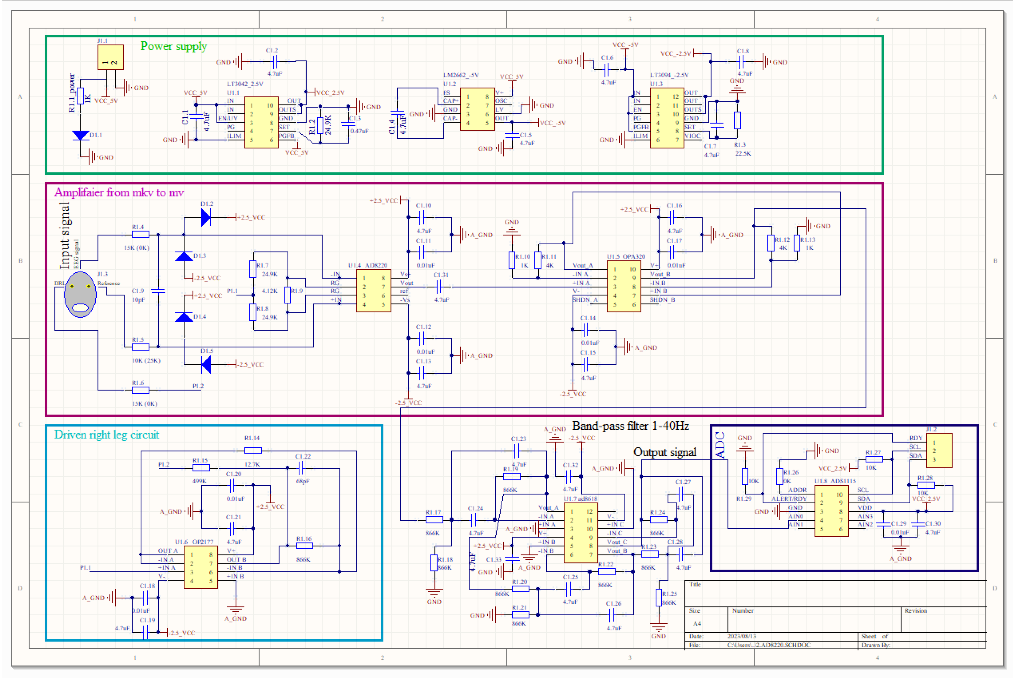
On
Figure 10 shows an structured electrical diagram of the device for the active electrode: power supply, amplifier part, driven right leg circuit, band-pass filter and ADC.
4. Evaluation of Device Performance
In order to validate the functionality and effectiveness of the device, a comprehensive assessment encompassing technical tests and real-world trials is imperative.
4.1. Technical Assessment
4.1.1. Signal-to-Noise Ratio (SNR) Calculation
The Signal-to-Noise Ratio (SNR) is a unitless measure that quantifies the relationship between the power of the useful signal and the power of the noise. For our device, this metric holds particular significance as the noise level falls within the same microvolt range as the useful signal. The calculation of this indicator was based on the following formula:
where P is the average power for the useful signal and noise and A is the mean-square value of the amplitude for the useful signal and noise. A noise signal with a duration of 5 min was recorded for SNR test, details in the
Table 1.
4.1.2. Common Mode Rejection Ratio (CMRR) Computation
CMRR, which stands for Common-Mode Rejection Ratio, represents the relationship between the differential gain (ADIFF) and the common-mode gain (ACM). CMRR plays a fundamental role when dealing with differential input circuits. To determine the CMRR, we established connections to device, including the reference channel, to a 10 Hz, 40 mV DC sine wave using the Audio Precision AP2700. Subsequently, we computed the CMRR using the following method:
where Ad represents the power of amplifier, and Acm denotes the common mode gain, which is calculated as the peak output voltage divided by the peak input voltage, essentially representing the signal amplification factor. To achieve a 100 Hz cutoff frequency, we incorporate a nominal 1 mΩ resistor in the feedback path in parallel with a 1.5 nF capacitor. This cutoff frequency is intentionally wide enough to permit the passage of 50 Hz / 60 Hz noise. Allowing this noise is imperative for our feedback system because if any noise is present in the signal wire, it must also be present in the reference wire for consistency. CMRR values indicate effective common mode noise rejection, which contributes to overall signal accuracy. In the table presented characteristics signals for electrodes for 8 attempts during time when electrode was used in different positions.
4.2. Device Testing in Experimental Conditions
This chapter presents a validation of a compact EEG acquisition device designed to collect signals within a specific frequency range. The device with a diameter of 18 mm seamlessly combines various electronic components and design solutions. The primary goal of this chapter is to evaluate the device’s performance using blink tests as a means of assessing its effectiveness in capturing EEG signals and its potential application in the field of brain-computer interface (BCI).
4.2.1. Blinking Test
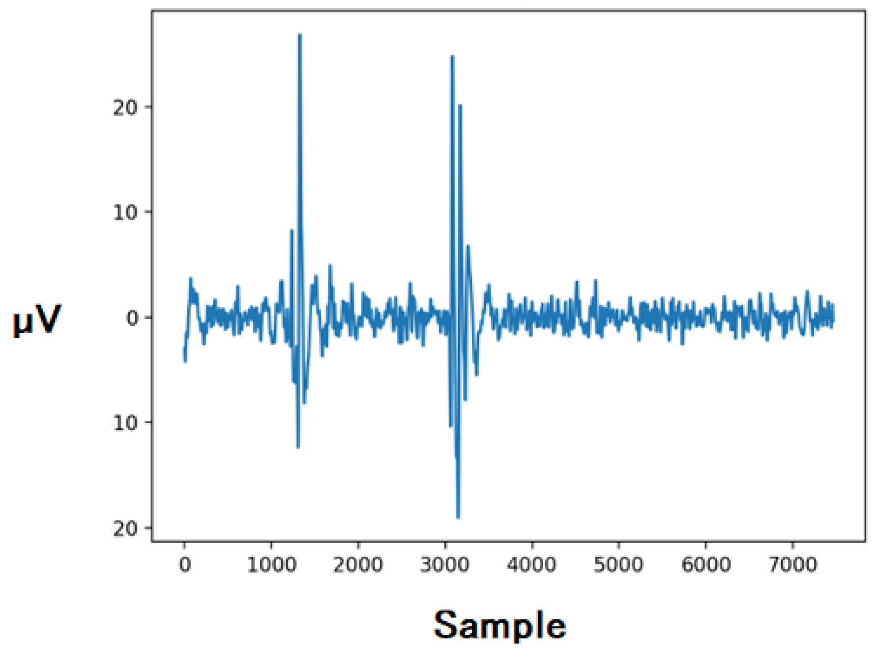
To evaluate the performance of the developed EEG recording device, a series of blink tests were performed. The participant was seated comfortably in a controlled environment with minimal external stimuli. The device was securely placed on the participant’s head in position F3 according to the international electrode positioning system 10-20, the participant, ensuring correct contact of the electrode with the skin. A series of controlled blinks was performed, generating characteristic EEG patterns associated with eye movements and muscle contractions. These patterns were chosen to challenge the device’s ability to accurately record rapid changes in electrical activity.
Figure 12 showed the process of measuring the blinking.
Blink tests provided valuable information on the performance of the developed EEG acquisition device. The device consistently captured and displayed blink-related EEG patterns, indicating its ability to accurately capture rapid changes in electrical activity. Noise levels were within acceptable limits, demonstrating the effectiveness of the noise reduction strategies used in the device design. In addition, the device demonstrated robust resistance to electrode displacement, maintaining stable signal reception even with small changes in electrode-to-skin contact.
4.2.2. Alpha Rhythm Test
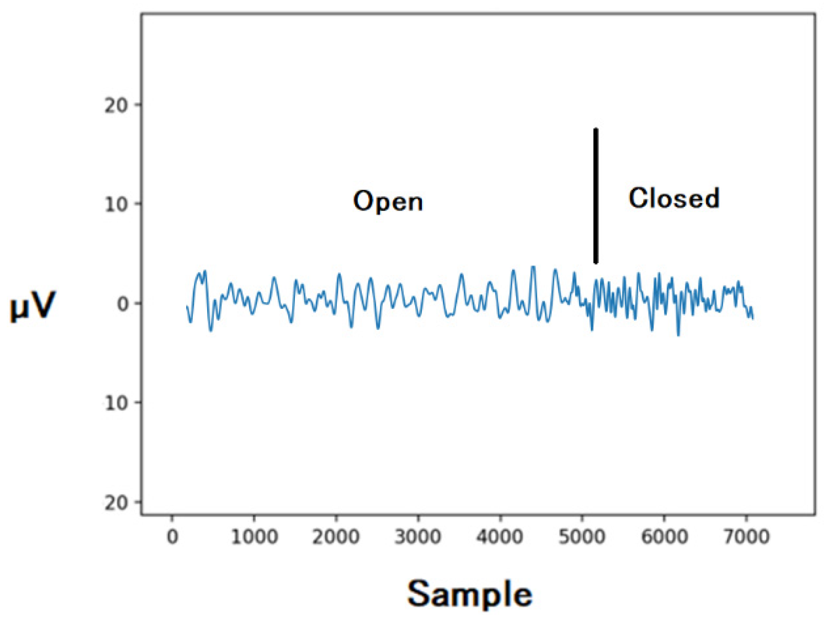
Next, we assessed the characteristics of the developed compact device for recording EEG by capturing and analyzing alpha rhythm signals with open and closed eyes,
Figure 13. Previously, the data was processed through a band-pass filter Butterworth filter with order—5 in the range 1 -30 Hz in Python language. To evaluate the device’s ability to detect alpha rhythm, participants were placed in two different conditions: eyes open and eyes closed. During the eyes-open experiment, participants were instructed to keep their eyes open while minimizing excessive eye movements. Conversely, the eyes-closed condition required participants to keep their eyes closed, minimizing visual input while allowing alpha dominance in the EEG signals,
Figure 13.
Analysis of alpha rhythm signals with eyes open and closed revealed consistent and distinct patterns. In the eyes-closed condition, a clear alpha rhythm was evident in the EEG data, which is consistent with the literature. The device effectively captured the characteristic frequency range associated with the alpha rhythm, demonstrating its ability to record specific neural oscillations. It is noteworthy that the device remained operational even with open eyes. Although alpha amplitude could be attenuated by visual stimuli, the device’s ability to differentiate between different conditions confirmed its reliability in real-world scenarios where external influences are unavoidable. The device’s ability to detect alpha rhythms with both eyes open and closed demonstrates its potential for monitoring cognitive states and attention levels in real time. This, in turn, could facilitate the development of adaptive BCIs that adapt to the user’s cognitive state.
Conclusion
This paper presents innovative contributions to the field of biodata acquisition, especially in the field of EEG signal amplification. The introduction of an open source active high precision signal amplifier represents a significant advance, addressing important aspects of signal accuracy, noise reduction and overall performance. With seamless integration of advanced electronics, careful design and innovative signal processing techniques, the compact 18mm diameter device provides a remarkable solution for improving EEG signal acquisition. The effectiveness of the proposed amplifier has been thoroughly demonstrated through technical tests and experimental studies.
Test data covering various parameters such as noise levels, electrode displacement immunity, common mode rejection ratio, input impedance. The use of the well-known silver chloride (Ag/AgCl) electrode in the evaluation process increases the applicability of the results and their potential for integration into broader research and practical applications.
Thus, the active, high-precision, open-source signal amplifier presented in this paper not only addresses the technical intricacies of EEG signal amplification, but also demonstrates the potential to make significant contributions to the ever-evolving field of brain-computer interface technology. As research continues to push the boundaries of our understanding of the human brain, the amplifier’s innovative design and comprehensive performance evaluations make it a cornerstone for future advances, further bridging the gap between biology and technology.
References
- C. Fonseca et al., “A Novel Dry Active Electrode for EEG Recording,” in IEEE Transactions on Biomedical Engineering, vol. 54, no. 1, pp. 162-165, Jan. 2007. [CrossRef]
- Rakhmatulin, I., Gan, Y. (2021). Review Dry and Non-Contact EEG Electrodes for 2010-2021 Years. [CrossRef]
- Rakhmatulin, I. (2021). The electronic board to replace the reference voltage on the earlobe for EEG measurement. Measurement. Volume 173, March 2021, 108673. [CrossRef]
- M. Guermandi, R. Cardu, E. Franchi Scarselli and R. Guerrieri, “Active Electrode IC for EEG and Electrical Impedance Tomography With Continuous Monitoring of Contact Impedance,” in IEEE Transactions on Biomedical Circuits and Systems, vol. 9, no. 1, pp. 21-33, Feb. 2015. [CrossRef]
- A. Dabbaghian and H. Kassiriю An Active Electrode IC with Embedded Analog CMRR Enhancement for Interference- and Gain-Mismatch-Resilient EEG Recording,” 2021 IEEE Biomedical Circuits and Systems Conference (BioCAS), Berlin, Germany, 2021, pp. 01-05. [CrossRef]
- Kyle E. Mathewson, Tyler J. L. Harrison, Sayeed A. D. Kizuk. High and dry? Comparing active dry EEG electrodes to active and passive wet electrodes. Volume54, Issue1. Special Issue: Re-centering science: Reliability, Robustness, and Reproducibility in Psychophysiological Research. January 2017. Pages 74-82. [CrossRef]
- Guang-Li Li et al. (2020). Review of semi-dry electrodes for EEG recording. Journal of Neural Engineering, 17(5). [CrossRef]
- Lopez-Gordo, M.A.; Sanchez-Morillo, D.; Valle, F.P. Dry EEG Electrodes. Sensors 2014, 14, 12847–12870. [Google Scholar] [CrossRef]
- Sarah Laszlo et al. (2014). A direct comparison of active and passive amplification electrodes in the same amplifier system. Journal of Neuroscience Methods, Volume 235, 30 September 2014, Pages 298-307. [CrossRef]
- Xu, Jiawei ; Yazicioglu, Refet Firat ; Van Hoof, Chris ; Makinwa, Kofi. (2018). Low Power Active Electrode ICs for Wearable EEG Acquisition.
- E. Habibzadeh Tonekabony Shad, M. Molinas and T. Ytterdal, “Impedance and Noise of Passive and Active Dry EEG Electrodes: A Review,” in IEEE Sensors Journal, vol. 20, no. 24, pp. 14565-14577, 15 Dec.15, 2020. [CrossRef]
- V. Mihajlović and B. Grundlehner, “The effect of force and electrode material on electrode-to-skin impedance,” 2012 IEEE Biomedical Circuits and Systems Conference (BioCAS), Hsinchu, Taiwan, 2012, pp. 57-60. [CrossRef]
- S. Patki et al., “Wireless EEG system with real time impedance monitoring and active electrodes,” 2012 IEEE Biomedical Circuits and Systems Conference (BioCAS), Hsinchu, Taiwan, 2012, pp. 108-111. [CrossRef]
- Y. Jiang et al., “Flexible and Stretchable Dry Active Electrodes With PDMS and Silver Flakes for Bio-Potentials Sensing Systems,” in IEEE Sensors Journal, vol. 21, no. 10, pp. 12255-12268, 15 May15, 2021. [CrossRef]
- Lee, S.; Shin, Y.; Kumar, A.; Kim, K.; Lee, H.-N. Two-Wired Active Spring-Loaded Dry Electrodes for EEG Measurements. Sensors 2019, 19, 4572. [CrossRef]
- Y. Li, X. Xu, Y. Liu and Y. Tian, “Analysis and Implement of ECG Front-End Signal Processing Circuit,” 2011 International Conference of Information Technology, Computer Engineering and Management Sciences, Nanjing, China, 2011, pp. 309-312. [CrossRef]
- C. De Capua, A. Meduri and R. Morello, “A Smart ECG Measurement System Based on Web-Service-Oriented Architecture for Telemedicine Applications,” in IEEE Transactions on Instrumentation and Measurement, vol. 59, no. 10, pp. 2530-2538, Oct. 2010. [CrossRef]
- Rakhmatulin, I., et al. Low-cost brain computer interface for everyday use. Exp Brain Res 239, 3573–3583 (2021). [CrossRef]
- Rakhmatuiln, M. Zhanikeev and A. Parfenov, “Raspberry PI Shield—for measure EEG (PIEEG),” 2021 5th International Conference on Electrical, Electronics, Communication, Computer Technologies and Optimization Techniques (ICEECCOT), Mysuru, India, 2021, pp. 410-413. [CrossRef]
- Rakhmatulin, I. (2023). Device JNEEG to convert Jetson Nano to brain-Computer interfaces. Short report I Rakhmatulin—arXiv preprint arXiv:2301.11110, 2023.
- Geddes, L.A., Roeder, R. Criteria for the Selection of Materials for Implanted Electrodes. Annals of Biomedical Engineering 31, 879–890 (2003). [CrossRef]
|
Disclaimer/Publisher’s Note: The statements, opinions and data contained in all publications are solely those of the individual author(s) and contributor(s) and not of MDPI and/or the editor(s). MDPI and/or the editor(s) disclaim responsibility for any injury to people or property resulting from any ideas, methods, instructions or products referred to in the content. |
© 2024 by the authors. Licensee MDPI, Basel, Switzerland. This article is an open access article distributed under the terms and conditions of the Creative Commons Attribution (CC BY) license (http://creativecommons.org/licenses/by/4.0/).

