1. Introduction
The demand for renewable energy sources has surged due to escalating power consumption and the pressing need for carbon-free energy [
1]. Wind power, a pivotal renewable source, has witnessed substantial growth, and has emerged as a dominant energy contributor in some regions supplanting conventional power generating plants. Various types of generators are employed in wind power plants [
2]:
Synchronous machine (SM);
Squirrel-cage induction machine (SCIM);
Wound rotor induction machine (WRIM) with variable rotor resistances;
Doubly fed induction machine (DFIM);
Brushless doubly fed induction machine (BDFIM);
Permanent magnet synchronous machine (PMSM).
Wind power plants are divided into four categories (types) based on turbine operating speed and power electronic conversion:
Type 1 – SCIM;
Type 2 – Wound Rotor IM with variable rotor resistance directly connected to the grid;
Type 3 – DFIM connected to the grid (partially) using power electronics;
Type 4 – Fully Inverter Based Distributed Energy Resources (IBDER).
Among these, Type 3 (DFIMs), owing to their wider variable speed operational advantages and limited need for capacitive compensation, are prominently utilized as generating units in land-based wind power plants. Type 4 (IBDERs) are the wind turbine of choice for offshore wind applications because of reduced maintenance needs and they do not require slip rings and gear boxes.
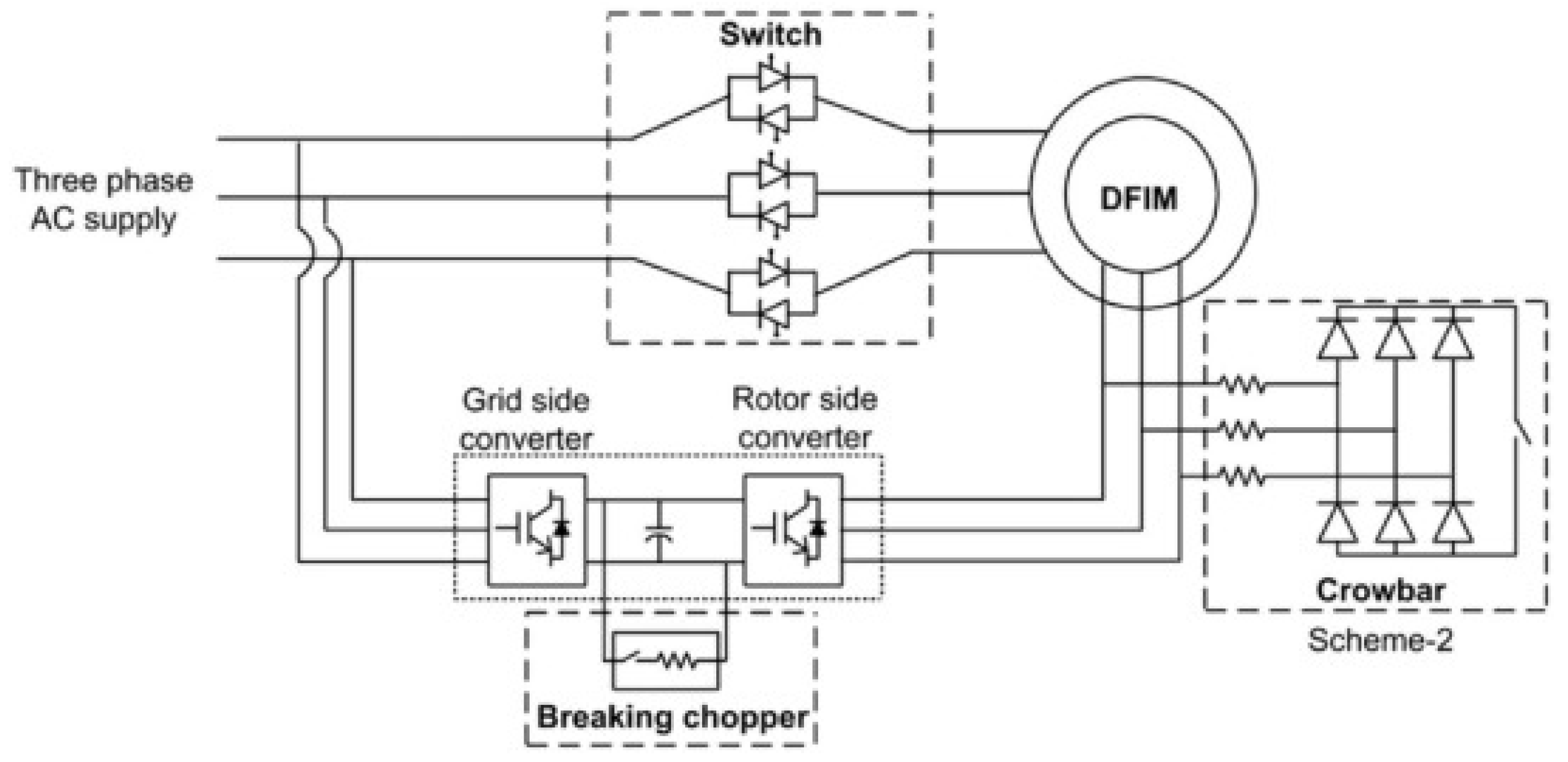
The architecture of a DFIM wind turbine, as illustrated in
Figure 1, emphasizes its key elements that influence how it behaves during voltage drops [
3].
In
Figure 1, there is a direct connection of the DFIM stator to the AC system supply, while the rotor windings are fed by a power converter responsible for regulating DFIM power generation which can exchange power with the ac system through a second converter. This back-to-back converter, if placed between the stator and the grid, needs to be sized appropriately to handle the entire generator’s power output, as is the case in an IBDER. In contrast, the rotor-side converter (RSC) is designed to handle 25-30% of the generator’s power, making it cost-effective and more widely utilized in land-based applications than its stator-side counterpart.
The rotor-based power converter has two main segments: the rotor-side converter (RSC), directly connected to the rotor and controlling rotor currents, and the grid-side converter (GSC) connected to the grid. These converters are interconnected by a DC link, with the GSC regulating the DC voltage that is crucial for DFIM controllability. A chopper is integrated into the system to manage and safeguard the DC link during voltage disturbances. Additionally, a set of resistors, often termed as a crowbar, is included as a part of the DFIM configuration, providing additional (last resort) protection for the converter. The RSC converter controls in modern type 3 wind turbines are at the point where the crowbars are much less likely to fire if they are even installed. Modifications to the configuration in
Figure 1 are implemented depending on the control or protection strategies that are used.
The direct connection of the stator side to the grid implies partial control of the generator, rendering it susceptible to grid disturbances. Consequently, voltage dips can result in substantial over currents. While these currents may aid in circuit breaker activation and isolation of faulty network segments, the electromagnetic coupling between the stator and rotor windings could induce high currents and voltages in the rotor windings, potentially overheating the rotor with overcurrent and damaging rotor insulation or the sensitive semiconductor components due to overvoltage in the rotor-side converters [
4].
Even small imbalances in the stator voltage, within the converter’s operating limits, can lead to highly unbalanced stator currents, causing torque fluctuations that produce acoustic noise and, at higher levels, may even cause damage to the rotor shaft, gearbox, and blade assembly [
5]. Over the years, various techniques have been developed to keep DFIMs in service during recovery from grid faults (low voltage periods). However, traditional practices involved disconnecting DFIMs during severe faults, exacerbating grid instability.
The modeling of DFIMs during fault conditions is important for industrial software that relies on simplistic yet effective models. This aspect is of critical importance for effective grid management. Acquiring knowledge and foreseeing grid behavior amid such instability periods is an imperative prerequisite for designing and overseeing protective measures, thereby maintaining grid stability.
The complexity and diversity of protection techniques, some of which will be presented in this paper, contribute to the challenge of accurately modeling DFIM behavior. This challenge can be extremely complex and very difficult to overcome. In this paper, we will present and analyze existing DFIM models, and assess their efficacy in delineating fault conditions. Consistent with recent trends, our objective is to explore the need for models with improved precision by evaluating the benefits of more sophisticated and detailed modeling techniques.
This paper consists of seven parts. The first section provides an introduction to the paper. The second section describes Fault Ride Through requirements. The third and fourth sections present passive and active protection techniques for DFIM, respectively. The fifth section discusses the modeling of DFIM during faults. A representative use case and results are provided in the sixth section, followed by future work and conclusions.
2. Fault Ride Through Requirements
Wind power plants contribute a substantial portion of total electrical energy in certain power systems at certain times of day, so they must remain connected to the grid during faults or sudden voltage fluctuations to ensure system recovery. This “ride through” requirement ensures they continue to support system stability without risking damage to their own infrastructure. Grid operators mandate this continuous operation during faults, known as fault ride-through (FRT) or low voltage ride-through (LVRT) regulations. IEEE standard 2800 has further strengthened these requirements.
As DFIMs are frequently employed as generators in wind power plants, grid operators require DFIM generators to remain connected and supply power to the network during faults, thus helping to maintain stable operation through the faulted period. Previously, wind generators with DFIMs were disconnected from the grid to protect the costly rotor-side converters from increased voltages and currents. However, modern grid codes demand that DFIMs have FRT capabilities [
6].
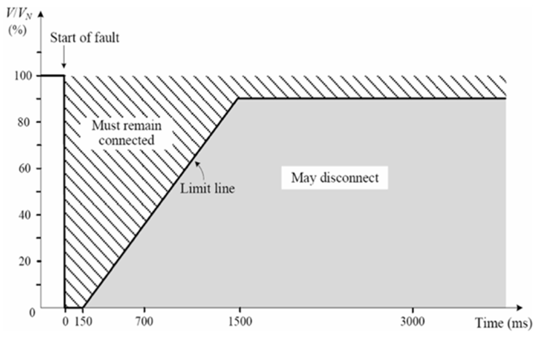
Figure 2 illustrates a simple FRT diagram with two distinctive areas designating where DFIMs should remain connected or may be disconnected [
5]. Each grid code prescribes the values that determine the borders between these two areas.
FRT implementation for wind power plants with DFIM generators addresses the following key aspects [
6]:
Safeguarding rotor power converter components against over currents and voltages;
Minimizing mechanical stress on gears and drive shafts;
Adhering to applicable grid codes concerning active and reactive power injection for supporting grid stability.
FRT requirements dictate that DFIMs, or any other generation source, should remain connected during low voltage periods, contributing to voltage stabilization by injecting active and reactive power into the electrical network. The injection of reactive power can positively impact other voltage-dependent generating units (such as –type 1 wind turbines) to protect them from tripping, and assist them in supporting grid stabilization [
7].
Numerous techniques aimed at achieving FRT have been devised, all reliant on the limitations of the RSC within the DFIM. These various methods, categorized according to the equipment and control employed, fall into two distinct groups: passive and active techniques [
5]. This significantly impacts DFIM’s fault response, and consequently the fault model required for calculations.
3. Passive Fault Ride Trough Techniques
Passive FRT techniques involve enhancing the DFIM with additional equipment designed to respond when specific variables (such as rotor current or voltage) exceed predefined limits, thereby safeguarding the expensive equipment from potential damage. These techniques can result in DFIM operation without its usual control, mimicking the behavior of a classical induction machine with altered parameters. Various passive FRT techniques will be introduced next.
3.1. Blade Pitch Angle Control Technique
In the case of faults or low voltage scenarios, the standard transfer of active power from the generator to the grid diminishes or halts, leading to an accumulation of excessive active power within the generating unit. This surge in active power leads to overloading of the power converter. Pitch control restricts the input mechanical power and can mitigate the build-up of active power in the generating unit. Pitch control operates by adjusting the angle of attack of each blade, thereby reducing the mechanical power and consequently constraining the rotor speed and reactive power consumption post-fault.
Figure 3 illustrates the fundamental concept of a pitch angle controller, where theta denotes the pitch angle [
5].
3.2. Crowbar Technique
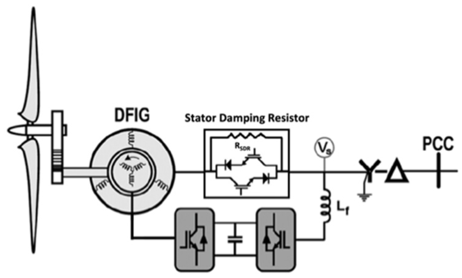
The primary safeguarding method for DFIMs during periods of voltage disturbances involves a collection of resistors termed a “crowbar.” This assembly of resistors is shown in
Figure 1. Under regular grid operating conditions, the crowbar is disconnected from the rotor windings. However, when voltage imbalances arise, resulting in excessive rotor currents and voltages, the rotor side power converter (RSC) disconnects the rotor from the grid, and the crowbar is activated. This action serves to shield the rotor from hazardous currents and voltages but renders the DFIM without control, causing it to function as a traditional induction machine.
The DFIM absorbs a significant amount of reactive power from the grid during the period without DFIM control, further contributing to grid voltage degradation. Excessively high crowbar resistance poses the risk of generating excessive transient rotor current, torque, and reactive power when the crowbar is disconnected [
8].
To ensure adequate damping and minimal energy consumption, the crowbar resistance can be up to 20 times the rotor resistance. Addressing the drawbacks associated with the traditional crowbar approach, an alternative crowbar arrangement was proposed in [
9], positioning the crowbar in series with the stator windings. Nevertheless, this configuration introduces conduction losses through bidirectional switches during normal operation.
To mitigate these losses with a stator crowbar, a Stator Damping Resistor (SDR) positioned in series with the stator windings and comprising three resistors in parallel with three bidirectional bypass static switches, as depicted in
Figure 4, was proposed. In standard conditions, the bidirectional static switches remain closed, preventing stator current from flowing through the SDR. Although stator crowbar techniques have demonstrated higher efficiency compared to rotor crowbars, they entail higher costs due to elevated current and voltage ratings. Careful consideration is essential when designing power electronics to minimize losses, a principle reason driving the proposal for the SDR.
3.3. Energy Capacitor and Energy Storage System Technique
As an option to recover energy dissipated in the dc link the Energy Capacitor System (ECS) and Energy Storage System (ESS) are methodologies rooted in storing and releasing surplus energy from the DC link using an extra capacitor or dedicated energy storage device. Their primary function is to safeguard the Insulated Gate Bipolar Transistors (IGBTs) and dc link capacitor against overvoltage situations. However, these techniques do not provide protection against high rotor currents. Therefore, the rotor converters need to be designed to handle these currents adequately to ensure continued controllability.
While ECS and ESS effectively smoothen the output power, they do not entirely eliminate the issues related to overcurrent and oscillations in electromagnetic torque. The incorporation of supplementary equipment and the need for oversizing the RSC result in increased costs [
5].
4. Active Fault Ride Trough Techniques
Active FRT methodologies include various control strategies complementing passive hardware solutions. These strategies mainly involve implementing feed-forward transient current control schemes for the RSC within the DFIM, often coupled with a crowbar. The crowbar serves as a protective measure of last resort for the converter, triggered in those cases when the control strategy fails to maintain rotor voltages and currents within acceptable limits.
4.1. RSC Compensation
This technique involves proactive operations of the rotor converter aimed at regulating rotor voltages and currents. This control mechanism counteracts transient rotor voltages and currents, ensuring they remain within permissible limits in combination with the converter’s capabilities. However, to detect changes in voltage and current values promptly, precise measurement equipment sensitive to rotor voltage and current disruptions is imperative.
In a proposed Feed-Forward Transient Current Control (FFTCC) scheme outlined in [
10], the injection of feed-forward current into the rotor windings compensates for low-voltage transients. Although the conventional rating of the RSC may not entirely offset all transient-induced voltages, this method minimizes transient rotor currents, thereby reducing instances of crowbar interventions. Nonetheless, this technique primarily aims at mitigation of transient rotor overcurrent rather than mitigating torque ripple.
A method utilizing injected rotor current to nullify both the DC and negative sequence components within the stator-flux linkage, achieving this without additional hardware or crowbar interventions is introduced in [
11]. A Feed-Forward Torque Control (FFTC) technique to effectively reduce torque ripples is presented in [
12]. A combined control strategy integrating a crowbar with a demagnetizing current is proposed in [
13]. While similar to the aforementioned feed-forward current, the demagnetizing current focuses on regulating the machine’s magnetic flux within prescribed limits. To stimulate reactive power production, a synchronous current must accompany this demagnetizing current.
Further enhancements are suggested in [
14], proposing the inclusion of virtual resistance and a demagnetizing current to counter negative magnetic flux within the machine.
4.2. Reactive Power Support
Various additional controllers, measurements, or supplementary equipment can be leveraged to support FRT capabilities. One such proposed approach involves the design and implementation of a series converter situated on the stator, aimed at curtailing the rise in current within the rotor, as detailed in [
15]. This system encompasses an active DC/AC inverter, three series transformers, and a DC bus capacitor. During voltage dips, this converter applies a decaying sinusoidal voltage rather than a pure sinusoidal voltage. This adjustment lowers the component ratings, rendering the system more feasible for practical applications while ensuring voltage and current values remain within permissible limits.
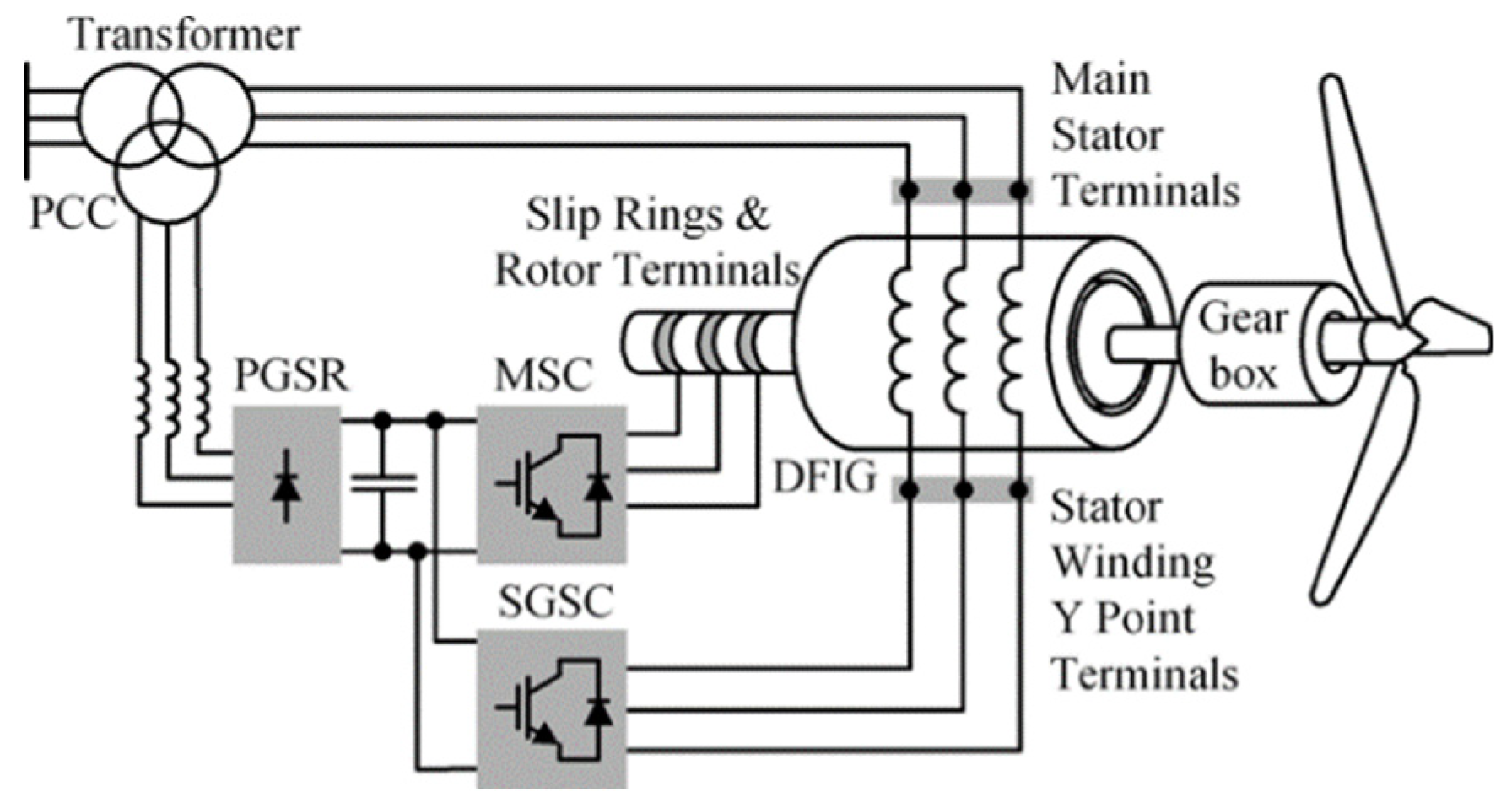
Another configuration introduced in [
16,
17] advocates the utilization of a parallel grid-side rectifier (PGSR) in tandem with a series grid-side converter (SGSC), illustrated in
Figure 5. This arrangement offers straightforward power processing capabilities and robust FRT features. The SGSC injects DC-link power into the grid by allowing for effective power flow control within a typical operational range, and it may not perform similarly at subsynchronous speeds. Consequently, a PGSR rated at a fraction of the total power serves to optimize system utilization in such scenarios.
4.3. Energy Storage in Rotating Masses
The rotating masses within a wind power generating plant provide the potential for the storage for surplus energy. This approach, however, is somewhat limited due to the fact that the gear ratio takes away a lot of the advantage. Employing a suitable control strategy for the power controllers and the pitch angle of the blades minimizes crowbar interruption time, ensuring continued controllability of the DFIM. These methodologies have been proposed in [
18,
19]. It’s noteworthy that [
18] introduces an additional damping resistance to dissipate excess energy. Simulation outcomes validate the efficacy of these approaches, even under high wind speeds.
4.4. BDFIM with an Advanced Control Strategy
Unlike an equivalent DFIM, the Brushless Doubly Fed Induction Machine (BDFIM) possesses a larger series leakage reactance, resulting in diminished transient currents. This inherent characteristic of the BDFIM allows it to withstand voltage dips without relying on a crowbar or any supplementary virtual impedance system. A unique control strategy enables FRT capabilities for the BDFIM, facilitating the provision of reactive power for grid support [
20].
4.5. Nonlinear Control
All the aforementioned active methodologies rely on linear control strategies, known for their simplicity and cost-effectiveness, thus widely adopted in industrial settings. Nonetheless, these techniques have limitations in addressing worst-case scenarios [
5], and nonlinear control strategies have emerged to address these limitations.
One such method is sliding mode control, a nonlinear control approach that modifies the dynamics of a nonlinear system through the application of a discontinuous control signal. The control signal drives the system trajectories to a “sliding surface” in the state space of the system to improve robustness and regulation [
21]. High Order Sliding Mode (HOSM) control, a derivative of this approach, presents advantages such as reduced mechanical stress on the system, finite reaching time, and improved robustness against unmodeled disturbances and dynamics [
22,
23,
24].
5. DFIM Modeling During the Recovery Period after Short Circuits
In light of their increasing significance as major contributors to overall energy production, DFIMs, as previously emphasized, play pivotal roles in the operational status of networks during recovery following the clearing of faults. Developing dynamic models for these machines is of significant importance. However, the simplicity and resilience of these models is necessary for their effective incorporation in industry software tools designed for extensive network applications. The wide array of passive and active FRT techniques complicates the establishment of a single model. While the most accurate method entails employing a dynamic model for DFIMs, it involves solving time-domain differential equations—a computationally demanding and time-intensive task, particularly for industrial software solutions aimed for solving large-scale electrical systems with tens of thousands of nodes. Therefore, striking a balance between precision and simplicity becomes imperative. Historically, disconnecting DFIMs from the grid led to oversimplified models that overlooked their substantial contributions to network stability during post-fault clearing conditions.
Two approaches found in the literature for modeling DFIMs during faults are:
DFIM as a Classical Induction Machine with heightened rotor resistance [
25];
5.1. DFIM as a Classical IM with Heighten Rotor Resistance
Most common FRT techniques use a crowbar as a response of last resort. When employed, crowbar resistance leads to short-circuiting rotor windings, redirecting the harmful high currents away from the sensitive converter equipment thus leaving DFIM without control. During this period the DFIM can be viewed as Type 2 wind turbine.
The short-circuit regime exhibits dynamic characteristics primarily influenced by alternating current machines. This dynamic behavior can be elucidated by examining an asynchronous machine undergoing a three-phase short circuit, previously operating in an idle state. The current waveforms across all components of the power system experiencing a short circuit at a given node have the following form:
where
represents the periodic steady-state current and
represents the direct current with the following form:
The total short circuit current is periodic with a decreasing magnitude with time constant
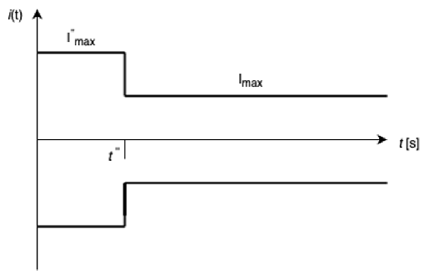
T. To simplify the short circuit representation and to be on the safe side, the current will be presented with two values in two time periods; representing the maximum values of the currents at the beginning of each period including the sub transient and steady state currents:
The graphical representation of this short circuit approximation is given in the following figure:
Figure 6.
Short circuit current approximations.
Figure 6.
Short circuit current approximations.
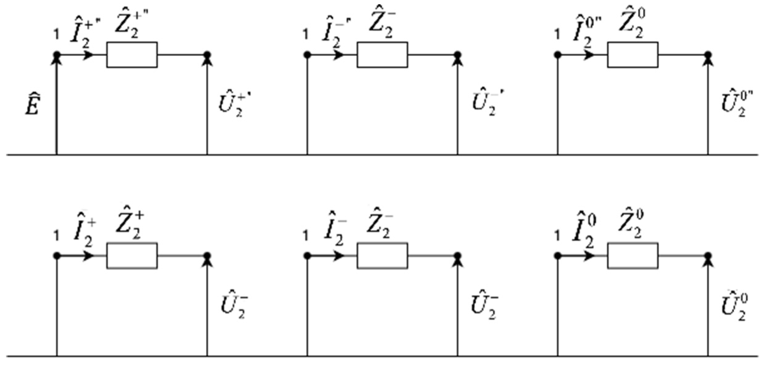
When dealing with asynchronous machines directly linked to the grid in calculations concerning short-circuit network regimes, Thevenin’s (Norton’s) equivalents are employed. Asynchronous machines, unlike synchronous ones, lack a transient sequence [
27]. For asynchronous machines, excitation is sourced from the grid itself, and voltage alteration due to a short circuit swiftly leads to the loss of excitation. Consequently, the model for an asynchronous machine lacks an ideal voltage generator in the steady-state time sequence. The model for the inverse sequence of an asynchronous machine remains identical to the direct axis model when viewed using Park’s transformation. Additionally, the symmetric component of the zero-sequence regime may often not exist due to the stator windings’ connection in a delta or ungrounded star configuration.
The representation of an asynchronous machine in calculations pertaining to short-circuit network regimes, is depicted in
Figure 7.
The impedances shown in
Figure 7 in the situation with an active crowbar contain additional resistance that refers to the activated crowbar resistance:
5.2. DFIM as IBDER
In situations where a DFIM experiences a low-current short circuit (for instance, if the short circuit occurs at a considerable distance from the DFIM connection point or some FRT technique keeps the currents under control), and the currents are insufficient to cause damage to power electronics, the crowbar mechanism remains inactive. This allows the inverter to retain control over the output current [
28,
29]. Under these circumstances and if required, the DFIM can be modeled in the same manner as an IBDER [
26] (IEEE 2800 has different response requirements during faults for type 3 machines than for type 4 or PV).
In this paper, the assessment of a short circuit’s “severity” is based on the voltage measurement at the specific node where the DFIM connects to the grid at the time of the fault event and the rotor current levels during the short circuit. If the voltage at this connection point falls below a predetermined threshold, it is assumed that the crowbar mechanism will activate. This situation occurs when the short circuit is in close proximity to the DFIM-connected node, signifying a critical scenario for the DFIM under consideration. Conversely, if the voltage at the DFIM connection point remains above the threshold, it is assumed that the crowbar will remain inactive, allowing the inverter to maintain control over the output current. This case arises when the short circuit is situated at a considerable distance from the DFIM-connected node, indicating a less critical scenario for the considered DFIM.
If the DFIM inverter is protected by a chopper, it allows for much better current control during a short circuit event. The chopper ensures the inverter remains active, limiting the short-circuit current, regardless of its proximity to the DFIM. Therefore, the chopper enables the inverter to maintain control over the output current during a short circuit. A DFIM equipped with a chopper is modeled in the same manner as an IBDER.
If any type of protection is applied to the DFIM to keep the machine under control (crowbar inactive), the DFIM can be modeled as an IBDER. An IBDER has total control over the currents, same as the DFIM has when not under a faulted state.
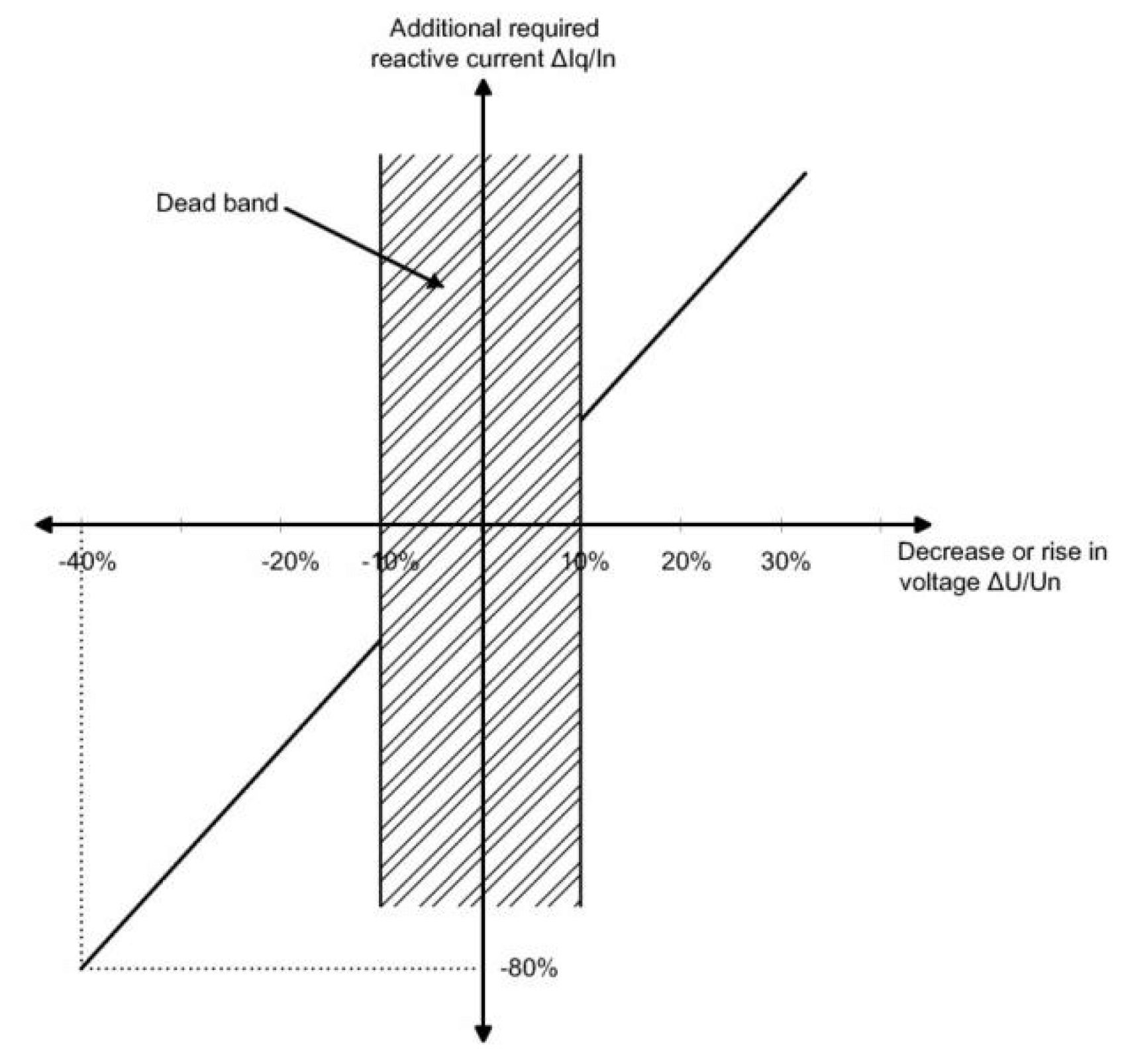
The currents that are injected into the grid during the faulted period depend on the FRT requirements. One such model is presented in [
26]. This model is based on Irish and German distribution codes that mandate the DER (in our case DFIM) to provide reactive current at the generator’s Point of Common Coupling (PCC) with a contribution of 2% of the nominal current per percent of the voltage drop [
30,
31]. This implies that if the voltage drops by 50%, the IBDER’s reactive current should be 100% of its nominal current. This is depicted in
Figure 8. Nevertheless, IBDGs must adhere to strictly defined current limits (not exceeding 120-150% of the nominal current depending on the vendor) to safeguard vulnerable power electronic devices. Hence, in instances of severe voltage drops (exceeding 75%), the reactive current from IBDGs cannot surpass this limit.
The proposed models involve ideal current sources with positive sequence symmetrical currents, addressing a challenge related to the ratio of active and reactive components in the short-circuit regime. The calculation of these components is performed based on the positive sequence voltage values at the PCC of the DIFMs during the short-circuit event. With the system comprising NDFIM DIFMs, an iterative process is employed.
In the initial short-circuit iteration, DIFMs are ideal current sources with pre-fault currents. The system state is calculated using the IBFS procedure. Post-iteration, voltage approximations at all DIFMs PCCs (
) are obtained. Reactive currents’ phase angles (
) are then calculated based on voltage phase angles as follows:
Where are phase angles of the DIFMs’ reactive currents, and are phase angles of DIFMs’ voltages .
The voltage ratio between
and nominal voltage at node
i are calculated as:
Then based on the calculated voltage ratio, the ratios between magnitudes of reactive currents and nominal currents for all of the DIFMs are equal to:
from which the magnitudes of reactive currents are calculated as follows:
Finally, the magnitudes of reactive currents for all DIFMs are compared to their current limits (
). Subsequently, the fault currents for all IBDGs (
) are calculated accordingly:
6. Use Cases and Results
In this section, the proposed DFIM model presented in
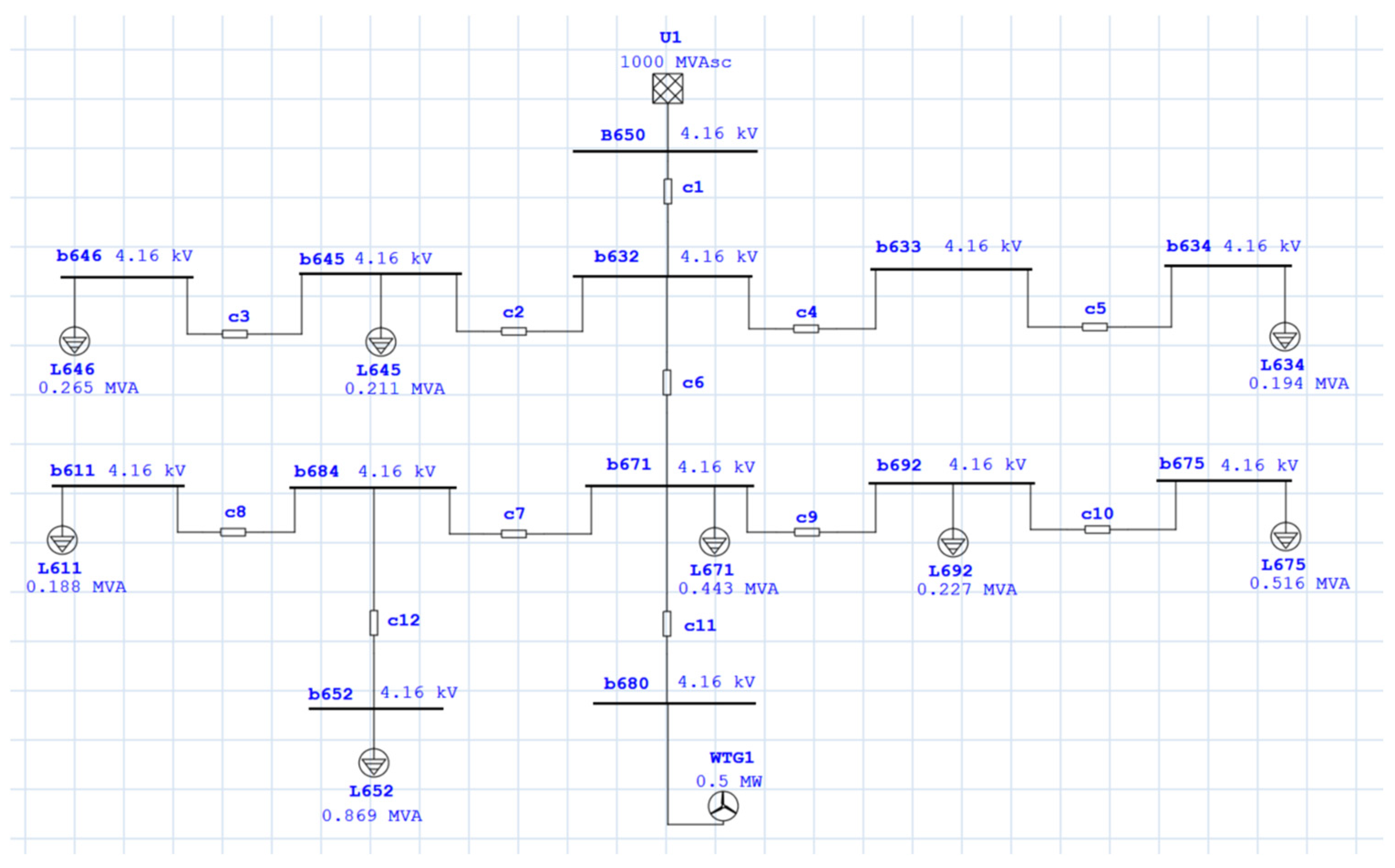
Section 5 is used to obtain the results of short circuit analysis for two simplified use (test) cases: using passive and active protection FRT techniques for DFIM in a wind turbine. The calculations are performed on a simplified IEEE 13 distribution network, with the standard IEEE 13 test feeder data available in [33]. All the calculations are performed within the ETAP software package.
For the short circuit studies conducted for these use cases, the following simplifying assumptions are applied to the original data:
-
The network is balanced and symmetrically loaded:
All nodes are connected with sections/lines; transformers, voltage regulators, and switches are replaced by sections;
Cables with the same catalog specifications represent all sections;
All loads are represented as static loads;
Fault impedance is assumed to be zero.
Figure 8.
Simplified IEEE 13 test feeder.
Figure 8.
Simplified IEEE 13 test feeder.
Power Grid data is given in
Table 1, the length and cable parameters are presented in
Table 2 and the data for consumers that are represented as static loads is given in
Table 3.
The following two subsections present the short circuit results obtained for the aforementioned network with two different FRT techniques used to protect the wind turbine DFIM connected to bus node 680. These are:
In both cases a three-phase fault is simulated at bus 671 (close to the wind generator).
6.1. DFIM with Crowbar
In this test case, the wind turbine DFIM is protected with a crowbar. The crowbar resistance is chosen to bound maximum DFIM currents at 125% of full load current. The proximity of the short circuit ensures that the voltage levels at the wind generator connection point (bus 680) are sufficnetly low so that the crowbar will be activated.
The following three tables present the results obtained through the short circuit calculations.
The peak short circuit current value is 17.265 A. From
Table 4 it can be seen that the majority of the supply to the short circuit comes from the grid, and the DFIM only injects a small current into the network during the short circuit. Most of the consumers are disconnected from any supply (either from the grid or the DFIM) during the short circuit.
Table 6 presents the voltage conditions in the grid. The voltage drop is at 100% at all the nodes that have been disconnected from any supply by the short circuit. Nodes closer to the grid supply expectedly have better voltage conditions. The contribution of the wind generator can be seen at bus node 680. The voltage drop is severe but not 100% due to the influence of the wind generator. This is only a small contribution but DFIM presence can be observed.
Table 4.
Node current contributions (fault and injected).
Table 4.
Node current contributions (fault and injected).
| ID |
Current
type |
Real
kA |
Imaginary
kA |
Magnitude
kA |
| 650 |
Grid
injection |
9.316 |
-6.910 |
11.598 |
| 671 |
Fault
current |
9.335 |
-7.020 |
11.68 |
| 680 |
WTG |
0.020 |
-0.110 |
0.112 |
Table 5.
Initial Symmetrical Fault Current contributions through sections.
Table 5.
Initial Symmetrical Fault Current contributions through sections.
| ID |
First
node |
Second
node |
Real
kA |
Imaginary
kA |
Magnitude
kA |
| c1 |
650 |
632 |
9.316 |
-6.910 |
11.598 |
| c6 |
632 |
671 |
9.316 |
-6.910 |
11.598 |
| c11 |
671 |
680 |
-0.020 |
0.110 |
0.112 |
Table 6.
Voltage.
| ID |
Voltage
% |
Voltage
Magnitude |
| 650 |
94.58 |
3.93 |
| 632 |
47.29 |
1.97 |
| 645 |
47.29 |
1.97 |
| 646 |
47.29 |
1.97 |
| 633 |
47.29 |
1.97 |
| 634 |
47.29 |
1.97 |
| 671 |
0 |
0 |
| 611 |
0 |
0 |
| 684 |
0 |
0 |
| 692 |
0 |
0 |
| 675 |
0 |
0 |
| 652 |
0 |
0 |
| 680 |
0.23 |
0.01 |
6.2. DFIM with FFTCC
In this test case, the wind turbine DFIM is protected with an active FRT technique (FFTCC). It is assumed that the active protection enables the DFIM to do a full FRT. This means that in this case, the DFIM will be fully controlable during the fault and will act as an IBDER. The control strategy is that the DFIM prioritizes injecting reactive power as much as possible.
The results of this test case are presented in the following three tables.
Table 7.
Node current contributions (fault and injected).
Table 7.
Node current contributions (fault and injected).
| ID |
Current
type |
Real
kA |
Imaginary
kA |
Magnitude
kA |
| 650 |
Grid
injection |
9.316 |
-6.910 |
11.598 |
| 671 |
Fault
current |
9.344 |
-7.378 |
11.906 |
| 680 |
WTG |
0.028 |
-0.469 |
0.469 |
Table 8.
Initial Symmetrical Fault Current contributions through sections.
Table 8.
Initial Symmetrical Fault Current contributions through sections.
| ID |
First
node |
Second
node |
Real
kA |
Imaginary
kA |
Magnitude
kA |
| c1 |
650 |
632 |
9.344 |
-7.378 |
11.906 |
| c6 |
632 |
671 |
9.316 |
-6.910 |
11.598 |
| c11 |
671 |
680 |
-0.028 |
0.469 |
0.469 |
Table 9.
Voltage.
| ID |
Voltage
% |
Voltage
Magnitude |
| 650 |
94.58 |
3.93 |
| 632 |
47.29 |
1.97 |
| 645 |
47.29 |
1.97 |
| 646 |
47.29 |
1.97 |
| 633 |
47.29 |
1.97 |
| 634 |
47.29 |
1.97 |
| 671 |
0 |
0 |
| 611 |
0 |
0 |
| 684 |
0 |
0 |
| 692 |
0 |
0 |
| 675 |
0 |
0 |
| 652 |
0 |
0 |
| 680 |
0.96 |
0.04 |
The peak short circuit current value is 18.205 A.
Results in the part of the network supplied by the grid are the same as in the previous test case, while a small but expected difference can be seen in the sections supplied by the DFIM.
An increase in reactive current injection at the DFIM connection point can be observed. This is due to a different controlling strategy. A slight difference in current injection and voltage level at the wind generator connection point is also observed when using active protection instead of passive protection. The voltage level is marginally higher (0.04 kV compared to 0.01 kV), though the voltage drop remains significant. The current injected by the DFIM is predominantly reactive, adhering to the given control during the short circuit, contrary to the previous test case (passive control - crowbar). Additionally, it is noteworthy that in this test case, the DFIM injects reactive current into the grid, whereas in the previous test case, it was consuming reactive current.
7. Lessons Learned and Future Work
The results of the test cases have illustrated that the DFIM (Doubly-Fed Induction Machine) model used during short circuit analysis has a significant impact on the outcomes of the analysis. The implications of this impact extend to all the applications that rely on short circuit calculations, such as relay protection, fault location, fault isolation, supply restoration, the selection of protective equipment, and other related functions in power systems. A short circuit event can trigger complex dynamic behaviors in electrical machines like the DFIM, and oversimplifying the model can lead to inaccurate analysis that directly affects system reliability and safety. Unfortunately, this issue has not yet been adequately addressed in the existing body of literature, where most studies still employ oversimplified models that do not accurately capture the complexities of different fault scenarios. These simplifications can lead to results that are less reliable, and this can be particularly problematic in applications where precise short circuit analysis is critical.
In our work, we have made an initial decision to represent the DFIM using two representative models for the same fault scenario—one for each category: active and passive fault ride-through (FRT) techniques. However, as indicated in [
26], this choice should ideally be made during the short circuit calculations themselves. A more adaptable approach is required, where the selection of the appropriate model depends dynamically on the specific conditions and severity of the fault, as well as the corresponding FRT technique. This highlights a critical need for further research in the area of DFIM modeling. The goal would be to develop an adaptive modeling technique that can differentiate between various levels of fault severity and select the appropriate model for more accurate analysis during the calculation process.
The significance of having such an adaptive DFIM model becomes even more evident when considering the consequences of misrepresentation of the results of the short circuit analysis. For instance, underestimating the fault’s severity or incorrectly applying an FRT technique could lead to improper functioning of relay protection, causing delays in isolating the fault or restoring the supply. Moreover, the selection of protective equipment, such as circuit breakers, could also be errorenous if the model does not accurately reflect the current conditions, leading to potential safety hazards or costly equipment failures.
In light of this, our future work will focus on refining and extending the DFIM models used in short circuit calculations, with an emphasis on enhancing accuracy and adaptability. We aim to analyze the specific conditions under which different models should be applied and explore the possibility of creating dynamic models that adaptin real-time as fault conditions change. This approach could pave the way for more precise and reliable short circuit analysis that is crucial for improving the performance of relay protection systems and ensuring the correct operation of protective devices during fault events.
Additionally, we will investigate the development of guidelines for selecting the appropriate DFIM model during fault conditions. These guidelines will help engineers and analysts make informed decisions on how to represent DFIMs dynamically, depending on the nature of the fault and the operational conditions of the power system. The goal is to ensure that short circuit analysis produces meaningful and reliable results, which in turn enhances the overall resilience and stability of power systems. As our test cases have demonstrated, the choice of the DFIM model can significantly influence the results of short circuit analysis, and thus the reliability of the entire system.
8. Conclusions
The increasing penetration of wind power plants in energy production has elevated expectations for the reliability and stability of wind power generation. This necessitates that renewable energy sources operate similarly to traditional power plants that use synchronous machines as generating units. Many wind power plants use DFIM due to their benefits with variable wind speeds and their cost-effectiveness. However, DFIMs are sensitive to voltage disturbances. Grid codes require DFIMs to have FRT capabilities, ensuring they remain connected during faults and assist the grid during low voltage periods. The main challenge for DFIM FRT is the expensive rotor converter, which is rated for only 25% of the total DFIM power. Consequently, protection equipment for the DFIM rotor and various controlling strategies are continuously being developed.
This paper discusses different equipment and control techniques designed to enable DFIM FRT. These techniques differ in their equipment and control strategies. While more equipment and complex strategies offer better protection for DFIMs, they also increase system costs, necessitating a balance between protection and expense. A small test study using a particular DFIM model has shown the that there is a small but yet noticeable difference in DFIM contribution to the grid state during SCs when using passive and active protection techniques.
Acknowledgements
We would like to express our sincere gratitude to Brian K. Johnson for his invaluable support and contributions to this paper.
References
- Bull, S. Renewable energy today and tomorrow. Proc. IEEE 2001, 89(8), 1216–1226. [Google Scholar] [CrossRef]
- Camm, E.; et al. Characteristics of Wind Turbine Generators for Wind Power Plants. In Proceedings of the IEEE PES General Meeting, Calgary, AB, Canada, 26–30 July 2009. [Google Scholar] [CrossRef]
- Morren, J.; de Haan, S. Ridethrough of wind turbines with doubly-fed induction generator during a voltage dip. IEEE Trans. Energy Convers. 2005, 20(2), 435–441. [Google Scholar] [CrossRef]
- Niiranen, J. Voltage dip ride-through of a doubly-fed generator equipped with an active crowbar. In Proceedings of the Nordic Wind Power Conference (NWPC), Goteborg, Sweden, 1–2 March 2004. [Google Scholar]
- Benbouzid, M.; Muyeen, S.M.; Khoucha, F. An Up-to-Date Review of Low-Voltage Ride-Through Techniques for Doubly-Fed Induction Generator-Based Wind Turbines. Int. J. Energy Convers. 2015, 3, 1–9. [Google Scholar]
- Dittrich, A.; Stoev, A. Comparison of fault ride-through for wind turbines with DFIM generators. In Proceedings of the 11th European Conference on Power Electronics and Applications, Dresden, Germany, 11–14 September 2005. [Google Scholar] [CrossRef]
- Sajadi, A.; Strezoski, L.; Clark, K.; Prica, M.; Loparo, K.A. Transmission system protection screening for integration of offshore wind power plants. Renewable Energy 2018, 125, 225–233. [Google Scholar] [CrossRef]
- Hansen, A.D.; Michalke, G. Fault ride-through capability of DFIG wind turbines. Renewable Energy 2007, 32(9), 1594–1610. [Google Scholar] [CrossRef]
- Noureldeen, O.; Hamdan, I. A novel controllable crowbar based on fault type protection technique for DFIG wind energy conversion system using adaptive neuro-fuzzy inference system. J. Prot. Control Mod. Power Syst. 2018, 3(35), 1–12. [Google Scholar] [CrossRef]
- Liang, J.; Qiao, W.; Harley, R.G. Feed-forward transient current control for low-voltage ride-through enhancement of DFIG wind turbines. IEEE Trans. Energy Convers. 2010, 25(3), 836–843. [Google Scholar] [CrossRef]
- Xiang, D.; Ran, L.; Tavner, P.J.; Yang, S. Control of a Doubly Fed Induction Generator in a Wind Turbine During Grid Fault Ride-Through. IEEE Trans. Energy Convers. 2006, 21, 3. [Google Scholar] [CrossRef]
- Liang, J.; Harley, R.G. Feed-forward transient compensation control for DFIG wind generators during both balanced and unbalanced grid disturbances. In Proceedings of the IEEE Energy Conversion Congress and Exposition, Phoenix, AZ, USA, 17–22 September 2011; pp. 2389–2396. [Google Scholar] [CrossRef]
- López, J.; Gubía, E.; Olea, E.; Ruiz, J.; Marroyo, L. Ride through of wind turbines with doubly fed induction generator under symmetrical voltage dips. IEEE Trans. Ind. Electron. 2009, 56(10), 4246–4254. [Google Scholar] [CrossRef]
- Hu, S.; Lin, X.; Kang, Y.; Zou, X. An improved low-voltage ride-through control strategy of doubly fed induction generator during grid faults. IEEE Trans. Power Electron. 2011, 26(12), 3653–3665. [Google Scholar] [CrossRef]
- Abdel-Baqi, O.; Nasiri, A. A dynamic LVRT solution for doubly-fed induction generators. IEEE Trans. Power Electron. 2010, 25(1), 193–196. [Google Scholar] [CrossRef]
- Flannery, P.S.; Venkataramanan, G. A fault tolerant doubly fed induction generator wind turbine using a parallel grid side rectifier and series grid side converter. IEEE Trans. Power Electron. 2008, 23(3), 1126–1135. [Google Scholar] [CrossRef]
- Flannery, P.S.; Venkataramanan, G. A unified architecture for doubly fed induction generator wind turbines using a parallel grid side rectifier and series grid side converter. In Proceedings of the IEEE Power Electronics Specialists Conference, Orlando, FL, USA, 17–21 June 2007; pp. 1442–1449. [Google Scholar] [CrossRef]
- Abdelsalam, I.; Adam, G.P.; Holliday, D.; Williams, B.W. Modified back-to-back current source converter and its application to wind energy conversion systems. IET Power Electron. 2014, 7(1), 1–12. [Google Scholar] [CrossRef]
- Yang, L.; Xu, Z.; Ostergaard, J.; Dong, Z.Y.; Wong, K.P. Advanced control strategy of DFIG wind turbines for power system fault ride-through. IEEE Trans. Power Syst. 2012, 27(2), 713–722. [Google Scholar] [CrossRef]
- Long, T.; Shao, S.; Li, C.Y.; Chun-Yin, E.; Abdi, R.A.; McMahon, R.A. Crowbarless fault ride-through of the brushless doubly fed induction generator in a wind turbine under symmetrical voltage dips. IEEE Trans. Ind. Electron. 2013, 60(7), 2833–2841. [Google Scholar] [CrossRef]
- Hossain, M.J.; Pota, H.R.; Ugrinovskii, V.A.; Ramos, R.A. Simultaneous STATCOM and pitch angle control for improved LVRT capability of fixed-speed wind turbines. IEEE Trans. Sustain. Energy 2010, 1(3), 142–151. [Google Scholar] [CrossRef]
- Benbouzid, M.E.H.; Beltran, B.; Amirat, Y.; Yao, G.; Han, J.; Mangel, H. Second-order sliding mode control for DFIG-based wind turbines fault ride-through capability enhancement. ISA Trans. 2014, 53(3), 827–833. [Google Scholar] [CrossRef]
- Benbouzid, M.E.H.; Beltran, B.; Ezzat, M.; Breton, S. DFIG driven wind turbine grid fault-tolerance using high-order sliding mode control. Int. Rev. Model. Simul. 2013, 6(1), 29–32. [Google Scholar]
- Beltran, B.; Benbouzid, M.E.H.; Ahmed-Ali, T. Second-order sliding mode control of a doubly fed induction generator driven wind turbine. IEEE Trans. Energy Convers. 2012, 27(2), 261–269. [Google Scholar] [CrossRef]
- Strezoski, L.; Prica, M.; Loparo, K.A. Generalized Δ-Circuit Concept for Integration of Distributed Generators in Online Short-Circuit Calculations. IEEE Transactions on Power Systems 2017, 32, 3237–3245. [Google Scholar] [CrossRef]
- Strezoski, L.; Katic, V.A.; Dumnic, B.; Prica, M. Short-Circuit Modeling of Inverter Based Distributed Generators Considering the FRT Requirements. In Proceedings of the IEEE North American Power Symposium (NAPS), Denver, CO, USA, 18–20 September 2016. [Google Scholar] [CrossRef]
- Strezoski, L.V.; Prica, M.D. Short-circuit analysis in large-scale distribution systems with high penetration of distributed generators. IEEE/CAA Journal of Automatica Sinica 2017, 4, 243–251. [Google Scholar] [CrossRef]
- Joint Working Group. Fault current contribution from wind plants. Report to the T&D Committee and the Power Systems Relaying and Control Committee of the IEEE Power and Energy Society, 2015.
- Van Tu, D.; Chaitusaney, S.; Yokoyama, A. Maximum-Allowable Distributed Generation Considering Fault Ride-Through Requirement and Reach Reduction of Utility Relay. IEEE Trans. Power Deliv. 2014, 29, 2, 534–541. [Google Scholar] [CrossRef]
- Tsili, M.; Papathanassiou, S. A review of grid code technical requirements for wind farms. IET Renew. Power Gener. 2009, 3, 3, 308–332. [Google Scholar] [CrossRef]
- Khairy, H.; EL-Shimy, M.; Hashem, G. Overview of grid code and operational requirements of grid-connected solar PV power plants. In Proceedings of the Industry Academia Collaboration (IAC) Conference, Cairo, Egypt, 6–8 April 2015; pp. 1–8. [Google Scholar]
- IEEE Power & Energy Society. Test Feeders. Available online: http://ewh.ieee.org/soc/pes/dsacom/testfeeders/index.html (accessed on 8 August 2024).
|
Disclaimer/Publisher’s Note: The statements, opinions and data contained in all publications are solely those of the individual author(s) and contributor(s) and not of MDPI and/or the editor(s). MDPI and/or the editor(s) disclaim responsibility for any injury to people or property resulting from any ideas, methods, instructions or products referred to in the content. |
© 2024 by the authors. Licensee MDPI, Basel, Switzerland. This article is an open access article distributed under the terms and conditions of the Creative Commons Attribution (CC BY) license (http://creativecommons.org/licenses/by/4.0/).
