1. Introduction
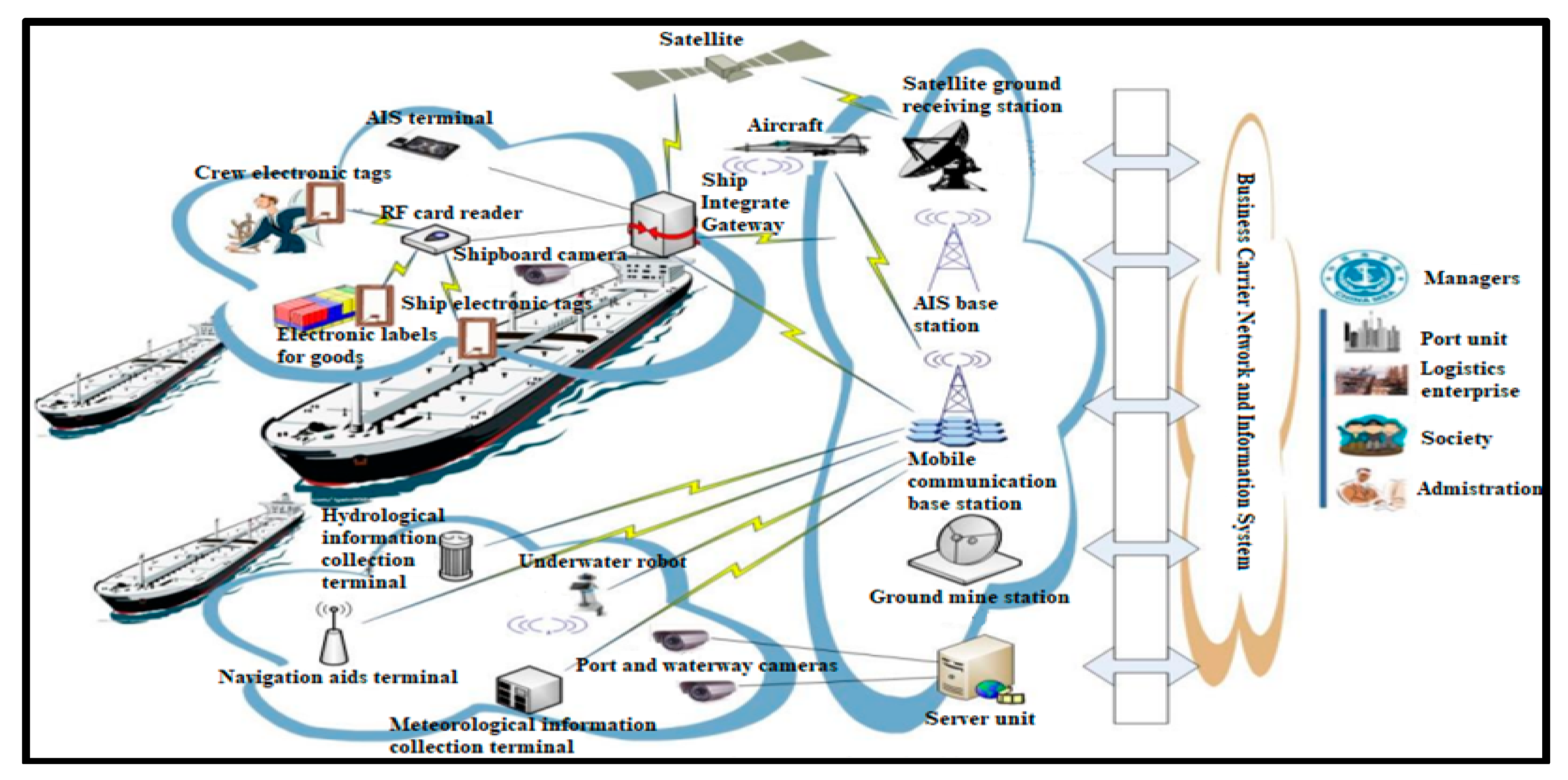
Around ports and secure areas at sea, vessels must comply with certain rules to avoid congestion, accidents and theft. Therefore, detecting vessels accurately is essential for sea operations in general and in particular in port and secure areas at sea. The research on the detection method of port vessels is of great significance to realize the real-time detection of vessels and improve the efficiency of the port vessels monitoring system. With the development and application of modern sea monitoring systems in various ports, most of the world's major ports are building extensive CCTV surveillance systems at sea. These ports are committed to building a real-time, intuitive, and whole-process CCTV monitoring system as shown in
Figure 1 [
1].
According to the geographical characteristics in the control area of the monitoring system and the source of scene image interference, the characteristics of the port surveillance videos are analyzed and summarized in different ways as follows [
2]:
The vessel target has a low contrast: In most cases, the surveillance camera is far away from the vessel target, relatively broad sea surface. The vessel target only occupies a few pixels in the video image, and its color is relatively close to the background of the sea surface. When the visibility of the sea surface is poor, it is difficult to spot the target from the image.
The noise interference is large, and the sea environment is complex: The regional changes caused by the waves on the sea surface are similar to the shape and size of the vessel target, which easily causes false detection of the vessel. Large areas of sea surface ripples are difficult to remove by common filtering methods. The change in lighting and the movement of the clouds cause a large area of background change on the port video image.
The vessel moves slowly: Under long-distance observation, the position of the vessel target on the image changes slowly, and the difference between the two images is only a few pixels. Thus, it is easy to cause the void phenomenon in the central area of the vessel target when using the detection method of moving targets.
Real-time processing of video: The vessel detection method based on surveillance video should not only ensure the accuracy of system detection but also require real-time processing of video. In order to facilitate the real-time observation of the test results by maritime regulators, the algorithm is required to be robust.
Recently, much research has been carried out in this field. Li et al. [
3] proposes the use of a range-Doppler processing to improve the signal-to-noise ratio (SNR) before computing the moving target's trajectory, based on the continuously bistatic range. This technology uses the Global Navigation Satellite Systems, which is reliable. However, the limited power budget offered by navigation satellites is its primary concern. A hierarchical method is proposed to detect the vessels in inland rivers. It uses multi-spectral information to extract the regions of interest, and then the panchromatic band to extract vessel candidates; afterward, a mixture of multi-scale deformable part models and a histogram of the oriented gradient are used to detect the connected components and the clustered vessels. Finally, a back propagation neural network is performed to classify the vessel candidates [
4]. This method has the advantage that it can accurately detect vessels in inland rivers as well as in port areas. It can effectively eliminate the background noise and congestion interference at sea. However, it considers several mixed algorithms, which makes the use of this method very complex and difficult to use. Yu
et al. [
5] proposed a Multi-Head Self-Attention-You Only Look Once (MHSA-YOLO) method for ship object detection in inland rivers. To strengthen the feature information of the ship objects and reduce the interference of background information, the method incorporates MHSA into the feature extraction process. A more straightforward two-way feature pyramid is created throughout the feature fusion process to improve the fusing of feature information; making this method realize an accuracy detection of 97.59%. However, its processing time is low (about 4.7s to perform a correct detection). When it is getting dark, the detection accuracy is just 91.9%, meaning that this method does not perform well late in the evening. Morillas
et al. [
6] proposed the use of a block division technique, which splits the image into tiny pixel blocks that correspond to small vessel or non-vessel regions. The blocks are classified using the Support Vector Machine utilizing texture and color information that were taken from the blocks. Finally, it makes use of the reconstruction algorithm, which extracts the identified vessels and fixes the majority of incorrectly categorized blocks. This method is more computationally efficient because it captures the characteristics of regions more accurately. This method has a precision of around 98.14% for the final vessel detection and approximately 96.98% for the classification between vessel blocks and non-vessel blocks. However, the experiments were probably applied using large vessels. This is because when we apply this method with small vessels, it has been discovered that the detection accuracy is lower; that is, 93.3% and 90.8%, respectively. Gao
et al. [
7] proposed a new inter-frame difference algorithm for moving target detection. This approach uses texture and color features in a two-frame-difference approach. It can effectively detect vessels with an accuracy of about 94.7% with a processing time of 2.01s. However, the false alarm rate is higher for small vessels with low contrast. Tabi
et al [
8] designed vessel detections with its monitoring system using an automatic identification system and a geographic information system. The vessel detection approach uses mixed Gaussian background modeling. This approach results in a large area of cavity in the center of the hull. The accuracy of the detection system is about 92%. However, the processing time is 3.76 s, which is considered poor in engineering applications. Besides, this approach suffers from serious interference to the background update due to the large variations in sea surface illumination and the rapid change of cloud background.
All the methods mentioned above can effectively improve the SNR of an image, suppressing background interference. They can detect moving targets under a background with just a little noise. However, they detect small vessels without protecting the edge of the moving target signal from being blurred; this leads to congestion. Given the characteristics of the long distance between port surveillance cameras and vessels, detecting small vessels still presents many challenges, especially when it is getting dark and when they are moving slowly. This defect is caused by significant interference from sea surface noise. Therefore, this paper proposes an IMSM, which takes into account the noise of the sea environment as well as the movement of vessels in their real-time detection process. The primary input of this paper is recapped as follows.
The proposed improved multi-structural morphology approach is designed based on physics and intensive mathematical contexts that result in the accurate detection of vessel targets.
The deep Hough transform (DHT) together with OSTU-based adaptive threshold segmentation enables the removal of the irrelevant lines/occlusions on the image and converts the image into a binary map.
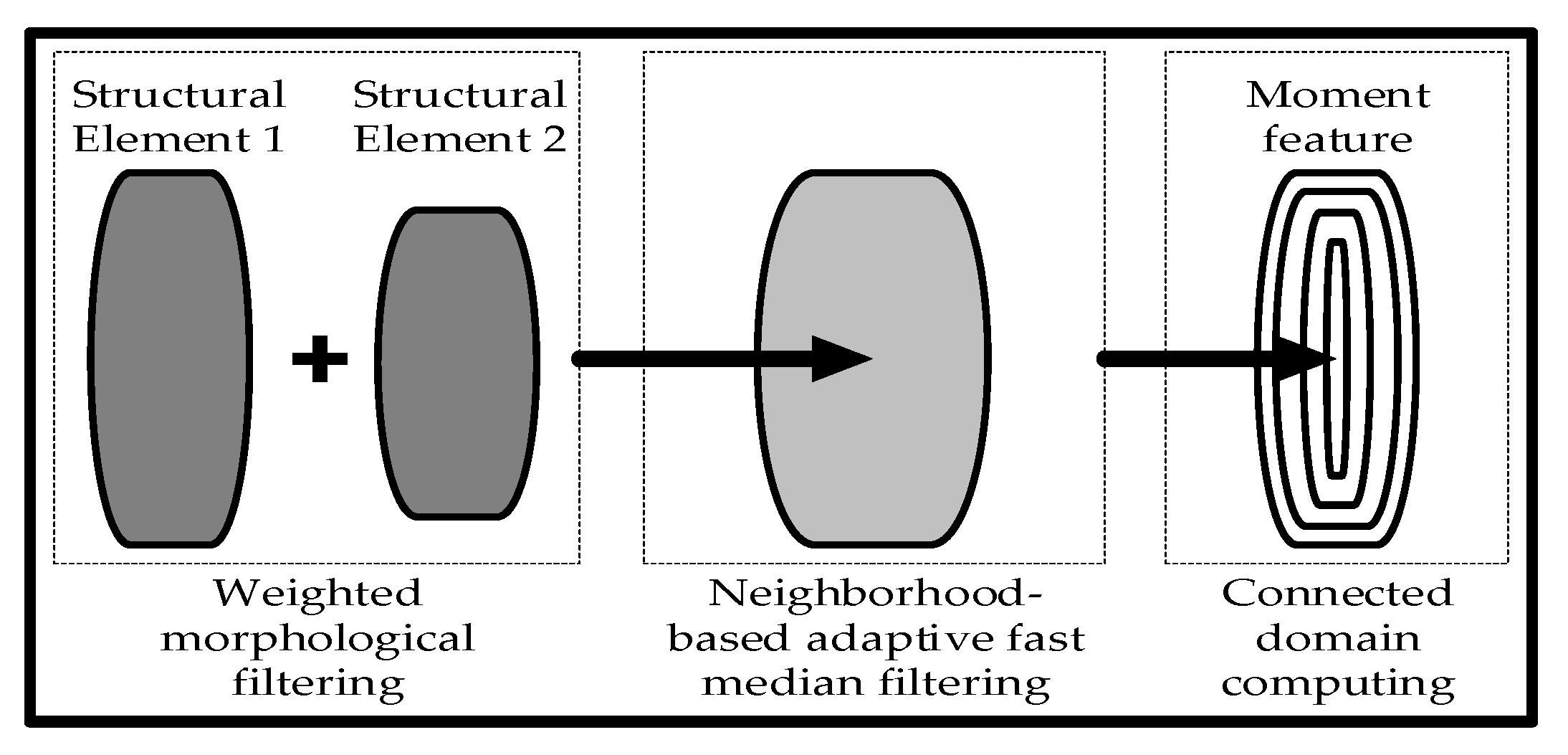
The combination of the weighted morphological filtering with neighborhood-based adaptive fast median filtering employing the associated domain makes it possible to clearly locate and monitor vessel movements in real-time.
The rest of this paper is organized as follows: port vessel detection system is developed in
Section 2; the multi-structural morphology filtering is designed and described in detail in
Section 3;
Section 4 and
Section 5 focuses and highlight the scientific application of the IMSM approach as well as the conclusion of this paper, respectively.
2. Port Vessel Detection System
2.1. Detection Process
Usually, a frame of image is read from the image sequence for detection; the detection process includes most of the elements presented in
Figure 1. Among them, there are the satellite, antennas, network equipment, server, cameras (video of the operation), etc.; they work together to give a well-defined result that is the output video image.
2.1.1. Satellite, Antennas, Servers, Etc.
They are made up of networks of transmit/receive modules. Each transmit/receive module in the antenna array has a tiny solid-state transmitter and receiver built into it. Together, these modules enable the coordinated and electronically controlled transmission and reception of radar signals. They detect the vessels around the monitoring area; they are designed to be able to withstand the harsh conditions at sea. Since vessels move with the waves in all directions, satellite antennas must perform real-time counter- movements in two directions to establish the vessel's position in relation to a satellite.
2.1.2. Camera
Cameras are functionally designed to record video inside an area that is under observation. To improve surveillance, they provide several functions, including motion detection, night vision, and PTZ (pan, tilt, and zoom) for focusing on certain regions of interest.
2.1.3. Image Processing Algorithm
It refers to the techniques used to convert an image from its native format into a digital image with a consistent structure. It is usually utilized to clean up the image and make it clear.
2.1.4. Output Video Image
The term video output describes a graphics interface that allows a digital camera or camcorder to send a video signal to an external viewing or recording device via a video output cable. It is a powerful tool that can improve the efficiency and quality of communication.
Indeed, when the original video image is not processed, it contains noise interference which is a mixture of nuisance alarms and/or false alarms that must be effectively eliminated to avoid misleading results. By definition, any signal produced by an adverse event is called a nuisance alarm; while a signal produced by the system's electronics that has nothing to do with a sensor or an event is called a false alarm. Thus, the equipment of the system must be not only in a good state but also well connected to each other. Besides, the image processing algorithm should be reliable and effective.
2.2. Tracking Path Analysis
The tracking problem can essentially be defined as the problem of estimating the path or trajectory of the target on the image when the target is moving [
9]. In order to observe the trajectory of the vessel target on the sea surface more intuitively, its path should be analyzed. Based on the premise that the direction and speed of each pixel in the video image will not change suddenly, it is considered that the path of moving target formation is coherent. The path coherence function reflects information such as the direction and velocity of the moving target. It can be used to represent a measure of consistency between the trajectory of a moving target and the constraint of motion so that the generated trajectory of a moving target is represented by a series of points in a two-dimensional projection plane:
where
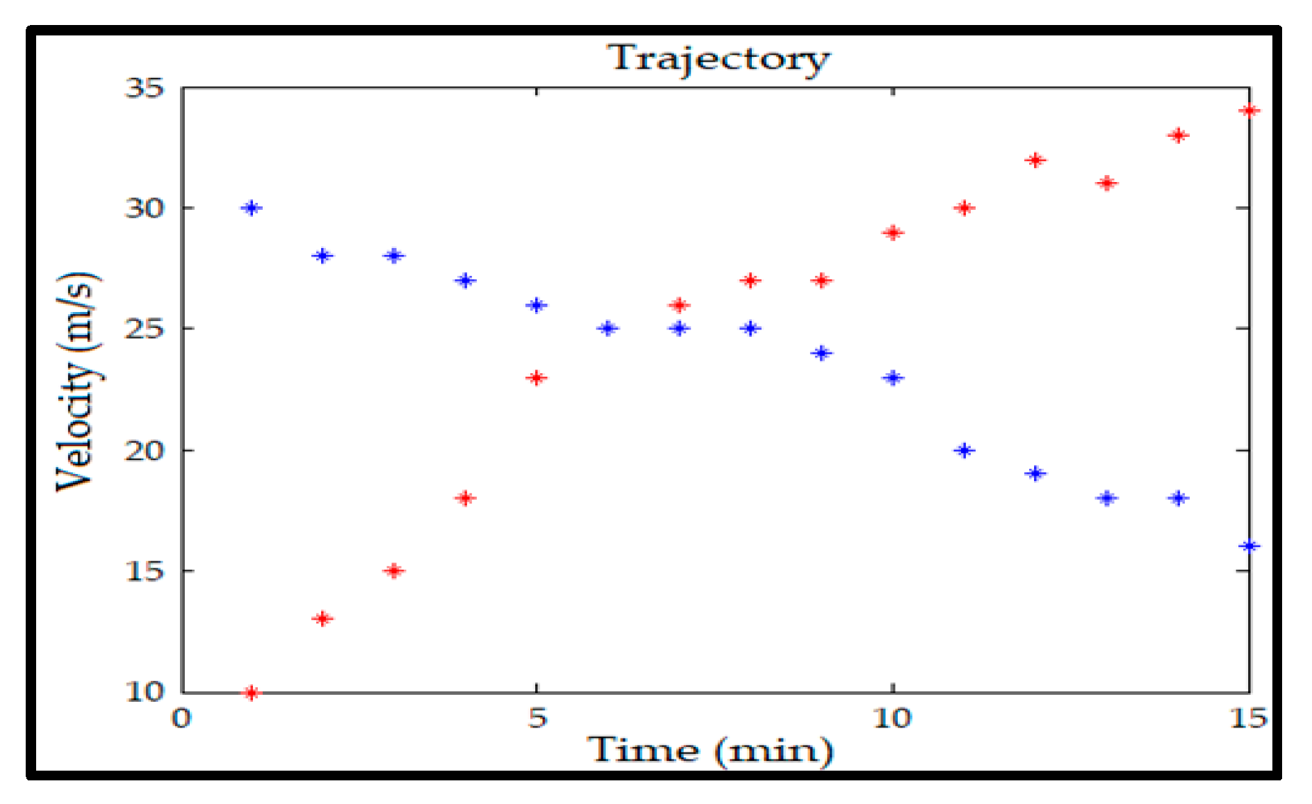
represents two independently moving target trajectories in the image sequence
, as shown in
Figure 2.
Let
represents the projected coordinates of the sequence point
on the image, and according to the correlation between the coordinates, the trajectory of the moving target can be represented in the form of a vector:
The deviation in the path represents the difference between the target and the coherent path, which can be used to measure the consistency of the path of the moving target. Let
denote the path deviation of point
in the image
:
where
is the path coherence function and
represents the motion vector from point
to point
. The path deviation
of the target
over the whole motion can be expressed as:
For
independent moving targets, the overall path deviation
can be defined as:
when path analysis is required for multiple targets at the same time, this can be solved by minimizing the overall path deviation
.
Assuming that the video frame rate is high enough, it can be considered that the velocity and direction of motion of the target change smoothly between image sequences; at this time,
can be expressed as:
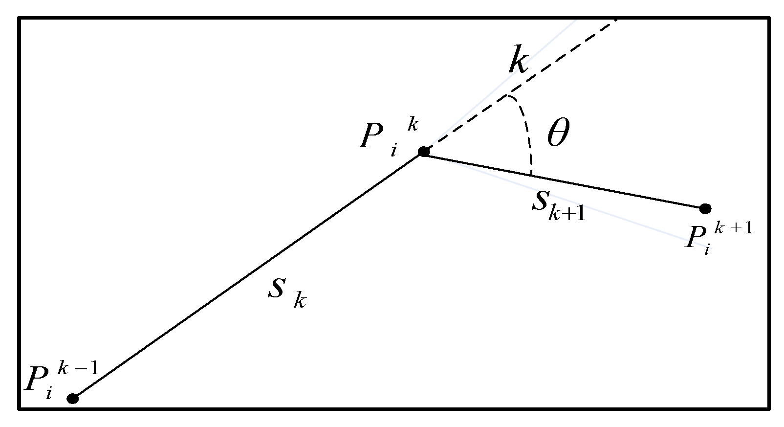
where
,
. The angle
, and the distance
and
are shown in
Figure 3; the weight coefficients
and
represent the importance of direction coherence and velocity coherence in path analysis, respectively.
When multiple independently moving targets are tracked at the same time, occlusion between targets occurs, and targets in some image frames may partially or completely disappear, which leads to errors in the target trajectory. Minimization of total trajectory deviation (Equation (5)) using a given path coherence function assumes that the same number of targets are detected in each image in an image sequence and that the detected target points always represent the same targets [
10]. However, once a moving target is occluded on the image, the assumptions cannot be satisfied.
To overcome the occlusion problem, other local trajectory constraints must be considered, allowing the trajectory to be incomplete in the event that the target is occluded, disappears, or is not detected. In this paper, according to the characteristics of the vessel’s slow motion speed on the image and the fact that the course will not change abruptly, it is assumed that the vessel is moving at a uniform speed [
11,
12,
13,
14], and the speed of each vessel is calculated based on the coordinate information obtained from the real-time detection of the vessel’s target. The vessel motion velocity
is taken as the motion assumption condition of the path coherence function
; at this time, the trajectory constraint of the vessel is set as:
is the maximum value of the path coherence function, Equation (8) represents any two consecutive trajectory points , and the displacement between must be less than a preset threshold . In Equation (9), when the target trajectory is non-complete, the next frame position of a target is predicted according to the target motion velocity and the video frame rate .
3. Design of the Improved Multi-Structural Morphology Filtering Approach
3.1. Vessel Target Detection Process
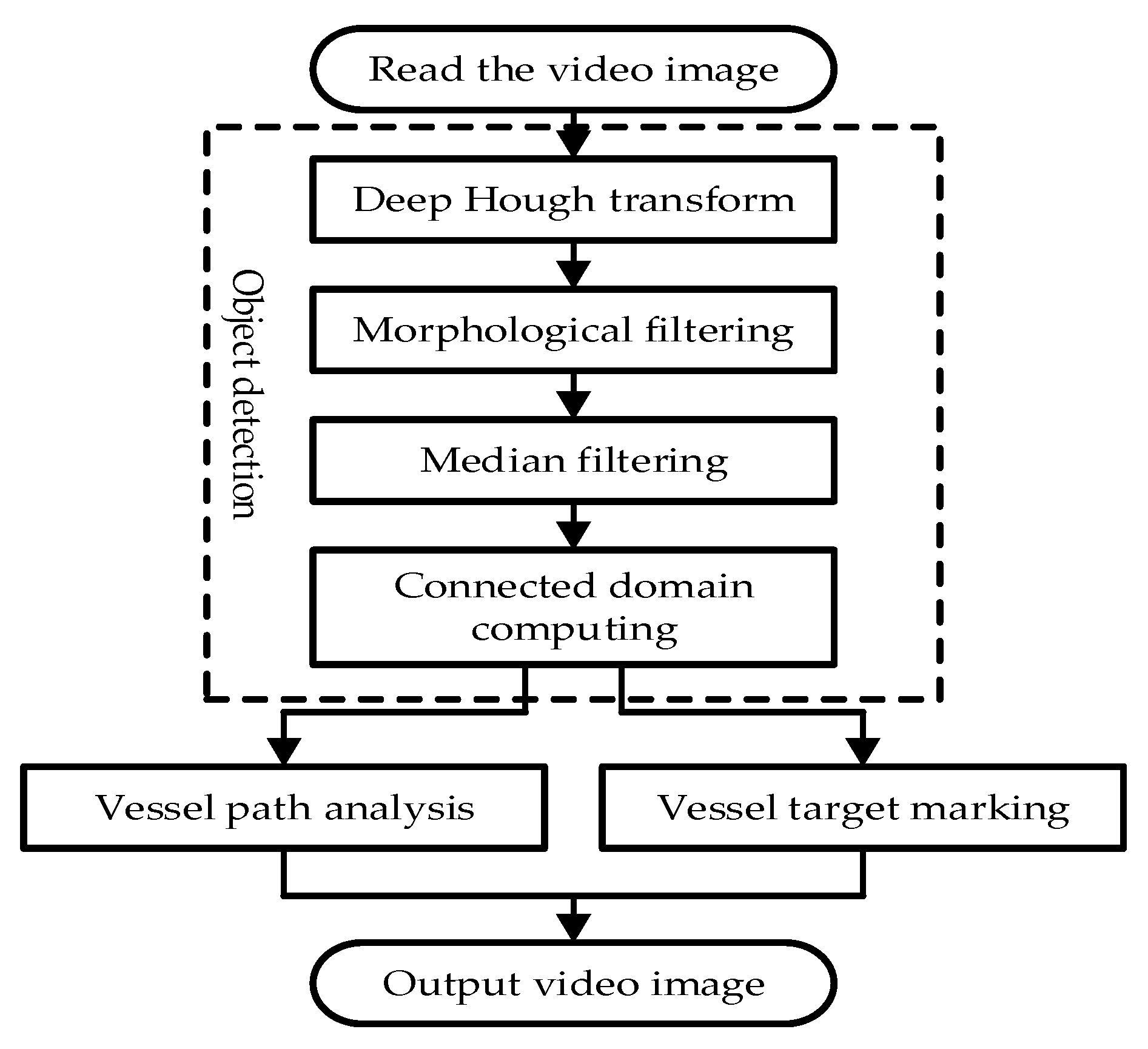
This section includes the following steps. After a frame of image is read from the image sequence for vessel target detection, the Hough transform algorithm together with the OSTU-based adaptive threshold segmentation method is used not only to eliminate the image's superfluous lines and occlusions, but also to convert the image into a binary map [
15,
16]. Afterward, the weighted morphological filtering of multiple groups of structural elements is used to separate the vessel target from the port background. Then, based on the geometric characteristics of the vessel, the neighbor-based adaptive fast median filtering is performed to filter out the impulse noise on the image. Subsequently, the connected domain labeling algorithm is performed to obtain the target information of the vessel and establish its morphological characteristics model. According to the target detection results, the vessel target is marked on the original image, and its movement trajectory is recorded. Finally, the processed video image is output. The detection process and the noise processing approach proposed in this paper are shown in
Figure 4 and
Figure 5, respectively.
Figure 5 establishes the dynamic morphological characteristic model of the vessel target to eliminate the noise interference of sea surface clutter on the final detection results.
3.2. Deep Hough Transform
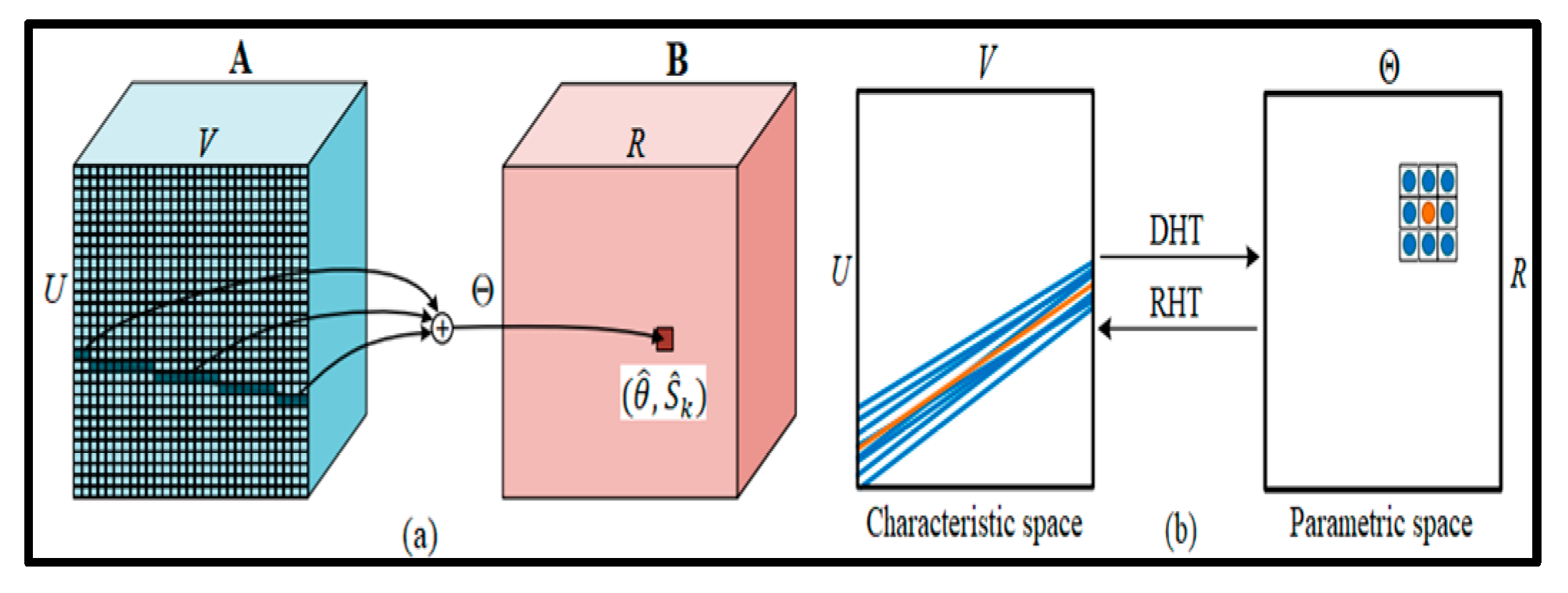
The light changes and occlusion result in irrelevant lines that are eliminated by means of the Deep DHT [
17,
18,
19]. As shown in
Figure 6, let considering a 2D image
; there is a straight line
that can be parameterized by two parameters.
is the angle between
and a distance
and a distance parameter
at the origin point
.
can be parameterized by bias
and slope
; besides, a reverse mapping can be performed to translate any valid
pair to a line instance. The line-to-parameters and the inverse mapping are defined as:
where
and
are bijective mapping,
and
are quantized into discrete bins that are processed by computer programs. The quantization can be formulated as follows:
where
and
are the quantized line parameters, while
and
are the quantization intervals for
and
, respectively. The number of quantization levels
and
can be written as:
Considering the input image
, the Convolution Neural Network characteristics
is first extracted; where
is the number of channels, while
and
are the spatial size. Then, the DHT takes
as the input image and produces the transformed characteristics,
. The size of the transformed characteristics
and
is determined by the quantization intervals as shown in Equation (12) [
20,
21]. As displayed in
Figure 6(a), for any line
on the image, the characteristics of every pixel along
are combined to
in the parametric space
:
where
is the positional index. Equation (11) determines
and
based on the characteristics of the line
, which are quantized into discrete grids by Equation (12). According to the number of quantization levels
and
, there is a unique line of candidates denoted
[
22]. For all these candidate lines, the DHT is performed; and their respective characteristics are associated with the corresponding position in
. In
Figure 6(b), characteristics in neighboring lines in characteristic space are converted to neighboring points in parametric space. In parametric space, a simple 3 × 3 convolutional operation makes it easy to capture contextual information for the center line (orange). It should be noted that DHT is order-independent in both characteristic space and parametric space, making it highly parallelizable [
23].
3.3. Weighted Morphological Filtering
Weighted morphology or mathematical morphology consists of a set of morphological algebraic operations that simplify image data, maintain the basic shape properties of images, and remove extraneous structures for analysis and recognition purposes [
24]. Morphological filtering uses nonlinear algebra tools to correct the signal by using the local characteristics of the signal; it can effectively filter out the noise in grayscale images [
25]. According to the basic mathematical morphological operations, various transformation operators can be derived, such as the combination of expansion and corrosion, and morphological open and closed operations can be derived. These morphological operations can be applied to analyze and process image processing algorithms related to shape and structure, including image segmentation [
26], feature extraction, edge detection, image filtering, etc. Let
represents the input image and
represents the structural elements, then corrosion and expansion are defined as:
Based on the principle of operation of corrosion and expansion, morphological open and closed operations can be defined separately as:
The top-hat operation is also a classical spatial filtering algorithm derived from the basic operation of mathematical morphology, which is often used as a high-pass filtering operator for image preprocessing [
27]. The operation has the effect of polishing the outer boundary of the image. It removes the small protrusions of the contour and compares the original image with the morphological image to obtain the Top-hat defined by:
Since morphological filtering is related to the size of the structure, the size of the structure determines the effect of high-pass filtering [
28]. When selecting a structure according to the structural characteristics of the target in the image, the smaller the size of the structure selected, the smaller the size of the target that can be preserved, and the better the low-frequency background filtering effect in the image. The minimum target size has the following approximation with the structure:
where
and
represent the maximum 2D size of the smallest target in the image plane, and the maximum 2D size of the structure used for morphological filtering, respectively.
The background suppression algorithm uses the morphological operation results to estimate the background components, and then subtracts it from the original image to obtain the target image without the background component [
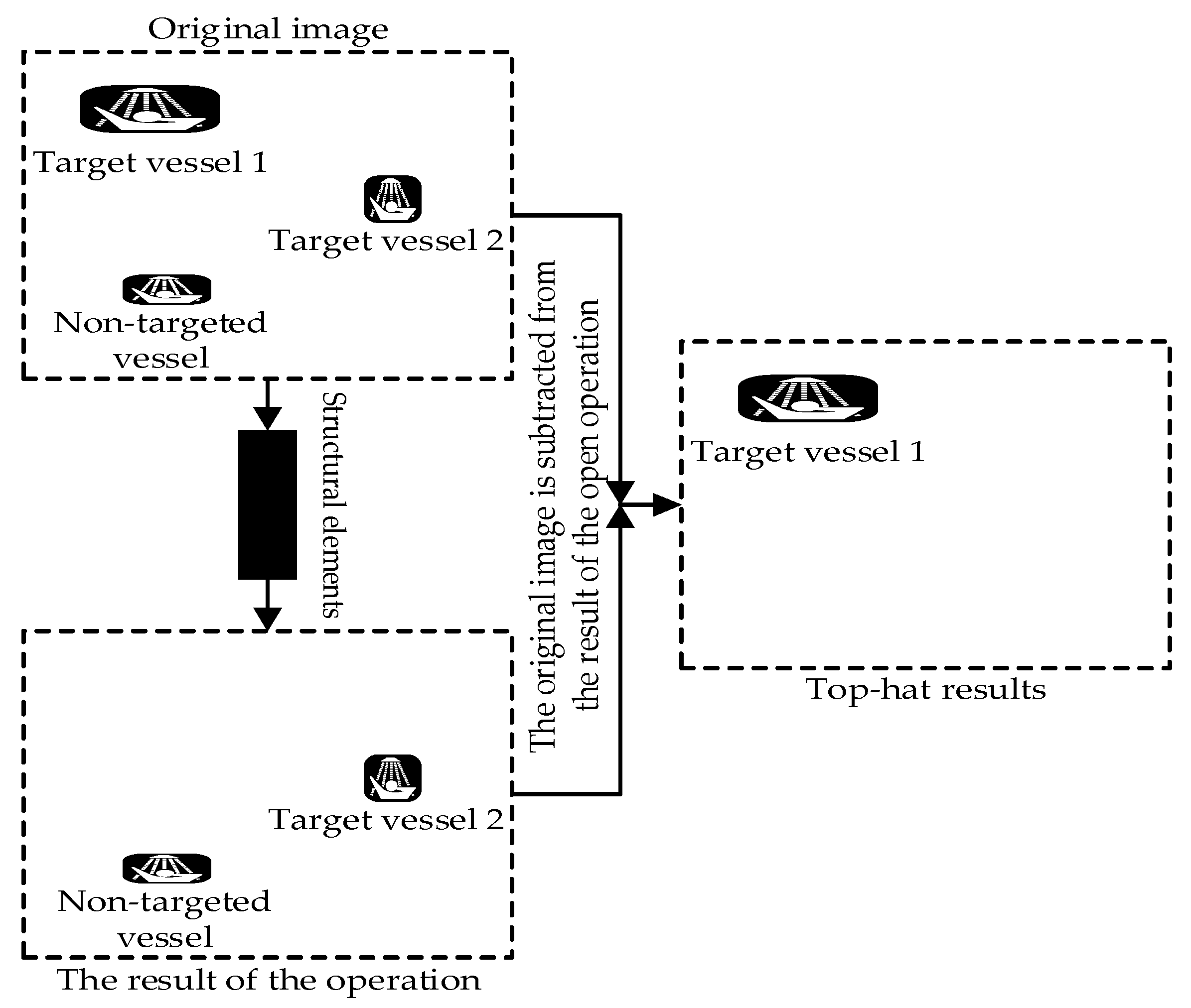
29]. However, when there are multiple targets in the image and the target size difference is large, the traditional morphological filtering of a single structural element will filter out the small targets at the same time as the low-frequency background, as shown in
Figure 7.
In order to avoid the shortcomings caused by the morphological filtering of a single structural element, this paper considers the difference in the geometric characteristics of the target and the background; and then, it adopts the weighted open operations of multiple structural elements [
30]. Let’s consider the input image
represented in the following equation:
where
is the weight coefficient, while
and
are the opening operations of different structures, respectively. The value of
can be adjusted according to the ratio of the information entropy of the filtered image to the information entropy of the original image. The selection of structural elements is the key to morphological filtering. Thus, as the structural operator of the non-convex set cannot obtain more useful information because most of the line segments connecting the two points are located outside the set, this algorithm selects the cruciform structural elements of the convex set according to the geometric characteristics of the vessel target. The structural elements of
and
are as follows:
The size of the structural element
is large, which will blur the edge details of the object, but the effect of filtering out background noise is good. The size of the structural element
is small, and its filtering effect is poor, but it can effectively protect the edge details of the object. The above two types of structural elements of different sizes are used for weighted open operation, which can filter out the background noise that is smaller in size compared with the structural elements. At the same time, the gray value of the image and the large brightness area are basically unaffected by filtering. Since the sea background noise is suppressed, small vessels can be clearly detected; however, their movements still need to be updated. Besides, this method can effectively improve the signal-to-noise ratio of an image by enhancing the target and suppressing background noise [
31]. However, it does not protect the edge of the moving target signal from being blurred. Therefore, the median filter is used not only to protect the edge of the moving target signal but also to filter out the impulse noise in the background image.
3.4. Neighbor-Based Adaptive fast Median Filtering
The filtering principle of the median filter is to sort the neighborhoods of a particular pixel in ascending or descending order and use the sorted median value as the pixel value of other pixels in the pixel neighborhood. That is, by selecting a filtering window, sorting the pixels in the window, and assigning the median value to the current pixel; the median filtering result of the entire image can be obtained by iterating through each pixel on the image [
32]. The expression for the median filter is as follows:
In the sea surface scene of the port, there is a lot of impulse noise, which causes serious interference to the target detection, so before the vessel detection, the image should be preprocessed to enhance the vessel target and suppress the impulse noise. The traditional median filtering uses a fixed-size window, and the loss of subtle points in the image is obvious when filtering [
33]. All the pixels in the window must be reordered every time the window is moved; for a window of
elements, the algorithm complexity is
. This algorithm does not consistently deliver updates as the window moves; therefore, in this paper, the fast median filtering based on histogram statistics is adopted. The median value is obtained indirectly by calculating the histogram of the pixels in the window. When the window moves, only the pixels moved in and out are updated. The appropriate equation is:
and
are the average time complexity of quick sorting of the
and
elements, respectively;
is a constant. It has been demonstrated that
, where
is a constant [
34]. The de-noising performance of median filtering is related to the density of the input noise signal. If the input noise signal is normally distributed and the mean value is zero, the variance of the output noise signal after median filtering is about:
where
is the length of the filter window,
is the input noise power,
is the mean input noise, and
is the input noise density function. From the above formula, the median filtering algorithm will effectively filter out the impulse noise with a pulse width of less than
.
In order to improve the median filter of fixed window size and the loss of fine points in the image, the method of increasing the filter window is adopted. At the same time, to avoid misjudging the pixels with higher pixel values at the edge of the target as noise points, the neighborhood pixels are used as the judgment basis for the output. For example, if the window value is [20,30,35,40,50,100], 100 is likely to be the target edge point, which is misjudged as noise. Let
be the gray value at the position
in the image,
be the current filtered window,
be the maximum filtered window,
and
are the maximum, minimum, and median values of gray in the filtered window, respectively;
be the number of pixels in the window equal to
. The process of adaptive median filtering is as follows [
35,
36,
37]:
If where T is the threshold, jumps to step 2; otherwise, increase the window . Then, quickly sort the median value for the new window until the above conditions are met, and the output .
-
If , then output ; otherwise, determine whether is true. Therefore
If it is true, then output .
If it is not true, then output .
3.5. Connected Domain Calculation Based on Moment Features
The morphological features of the vessel were obtained by using the contour-based connectivity domain marking method [
38]. The moment characteristics of the connected region are expressed as:
where
represents the region of the
-order moment,
denotes the central moment,
and
are the region point coordinates,
and
represent the region centroid coordinates. In this paper, the length of the region
, the height of the region
, the aspect ratio
, and the area of the region
, are used to describe the vessel target. These four quantities form a four-dimensional target feature vector
, which is directly deleted when it does not meet the set threshold in the binary image [
39]. The feature vector
must execute the vessel’s contour moment function.
4. Engineering Application Case
4.1. Simulation Environment and Data Acquisition
The applications were carried out as part of the East China Sea offshore wind energy project in Zhangjiagang. The surveillance camera used in this application case is located in the port of Zhangjiagang City, at about 800 m from the vessel target. Zhangjiagang port is an important hub for the transportation of goods and large equipment by sea in China. This port has become one of the largest international trading ports in China with a large flow of vessels; the main seaworthy vessels are bulk carriers, container vessels, cargo vessels, etc.
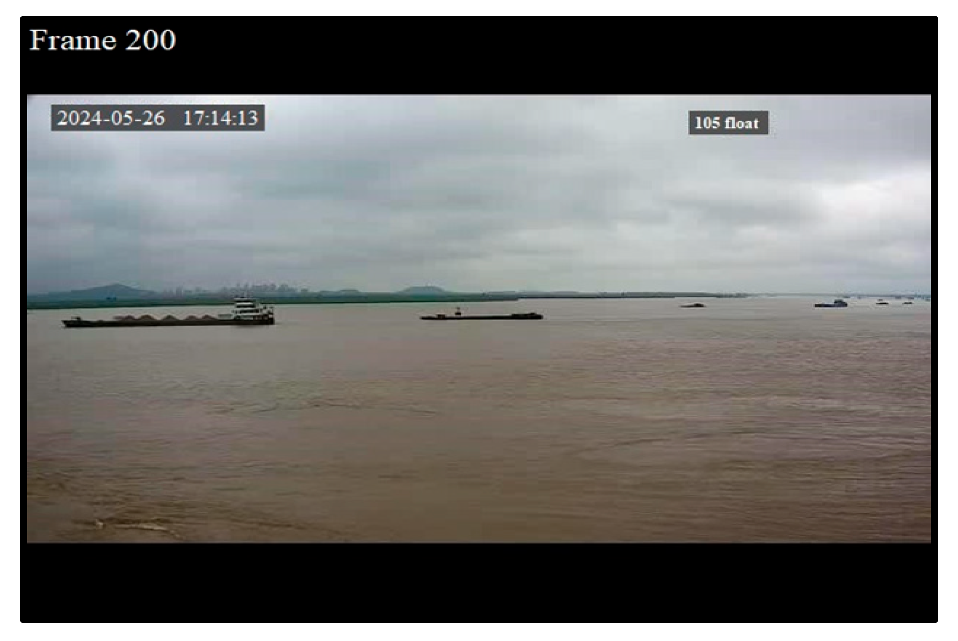
Figure 8 shows the video image taken from the port of Zhangjiagang; it is a real video that has a duration of 1 minute and 30 seconds, and its resolution is about
. As the characteristics of the simulation and development environment, a server was used; its memory is 4GB, the system platform is a 32-bit winXP system, the software implementation platform is VS2010 and OpenCV 2.4.8, and the video frame rate is 24fps.
4.2. Program Verification
A total of 750 frames of images were continuously collected from the port surveillance video; the length of each frame is 0.28s. The basic frame used in this application is frame 200. In order to verify the suppression performance of background noise by each algorithm used in this paper, the mean square error, peak signal-to-noise ratio, and information entropy of the results obtained before and after the use of the algorithm are calculated. The calculation formula will be as follows [
40,
41,
42,
43,
44,
45,
46,
47,
48,
49]:
where
is the mean square error,
is the original image,
is the open image,
is the peak signal-to-noise ratio,
is the maximum value of the image point color,
is the information entropy of the image,
is the total gray level of the image, and
is the probability distribution of pixels with a gray value of
. The calculation results for each algorithm, including morphological filtering, and median filtering method are shown in
Table 1 and
Table 2, respectively.
The specific steps to complete the proposed approach are as follows
4.2.1. First Step
Acquisition of the original video image. The input image is recorded as .
4.2.2. Second Step
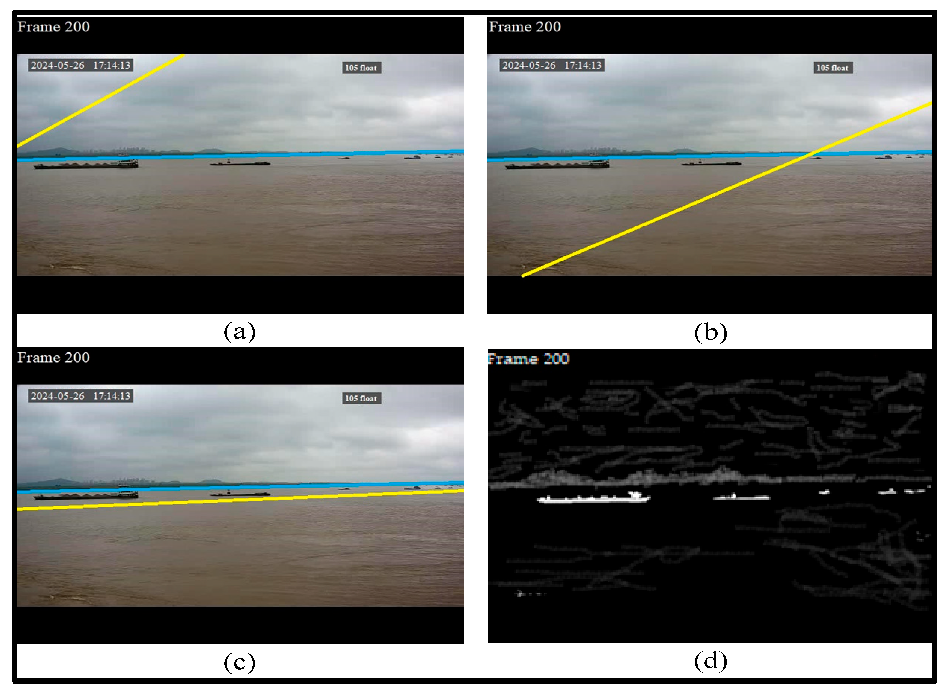
Deep Hough transform based on a line detector is used to detect and remove the irrelevant line caused by the light change and occlusion. The sea-sky background is segmented to reduce the scanning area and further improve the detection efficiency. Following the translation of the DHT features into the parametric space, grid location (θ, r) will march to features in the feature space along a whole line. These tasks are performed using Equations (10)–(13). After computing,
,
, and
. Entities close to the yellow line are translated to surrounding points near the target; the blue line separates the seawater from the sky. The results of this task are displayed in
Figure 9.
4.2.3. Third Step
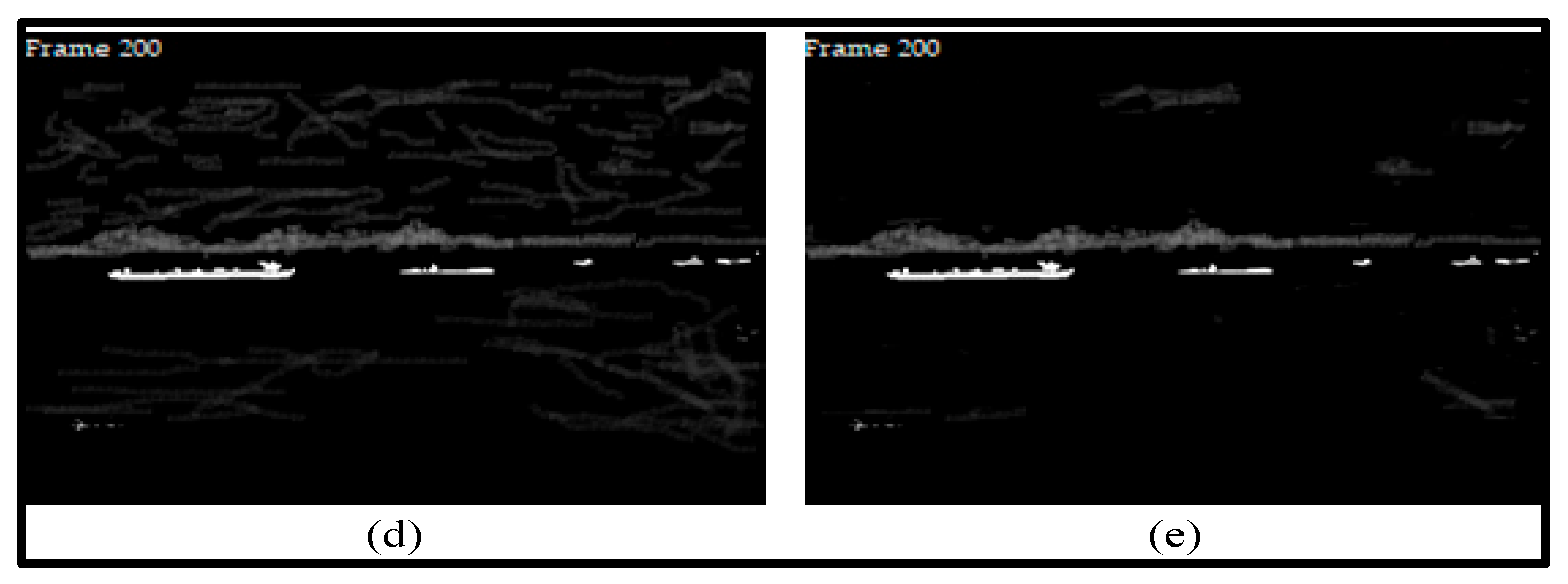
After the conversion of the image, it enters the weighted morphology process. A two-stage morphological filtering is performed, starting with the use of the open and close operations using Equations (20) and (21); the weight coefficient is
;
and
are the opening operations, and
is the structural element. Then, the Top-hat transform is used to polish the outer boundary of the image utilizing Equations (18) and (19). The results of these operations can be observed in
Figure 10.
Table 1 summarizes the morphological filtering algorithm performance.
Based on these results, it is obvious that the ripples (sea background noise) remaining in the image after using the weighted morphological filtering are significantly low. The MSE, and the number of corrugated bands, which are lower after filtering, confirm this. Since the image still has interference, thus the use of the median filter is necessary to remove them from the image.
4.2.4. Fourth Step
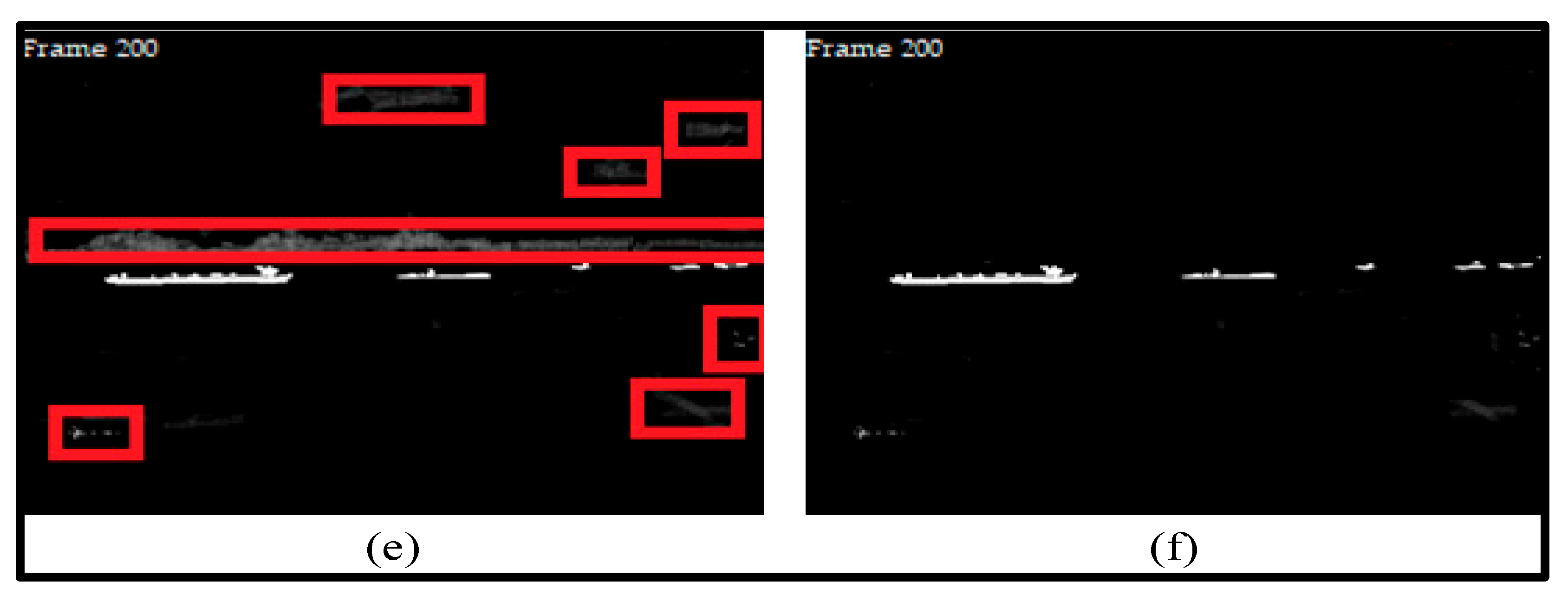
The neighborhood-based adaptive fast median filtering algorithm is adopted using Equations (22)–(24), to remove the impulse noise in the image. The length of the filter window is 4.9. The results before and after processing are displayed in
Figure 11, where
Figure 11 (e) is the resulting image after the morphological filter has been applied. It can be seen from the results that after processing, the random noise caused by the sky and the waves of the sea are almost all eliminated; the resulting profile is closer to the real target.
Table 2 shows the neighborhood-based adaptive fast median filtering algorithm performance.
The connected domain should be applied to locate and monitor the vessels movement in real-time.
4.2.5. Fifth Step
This step consists of computing the connected domain using Equations (25) and (26); the target feature vector
is calculated. The aspect ratio
and the area
are set according to multiple experiments. Therefore, the number of contours of multiple frames of images is counted and saved; and the influence of discontinuous surface clutter on the vessel detection results is excluded. When the target satisfies both
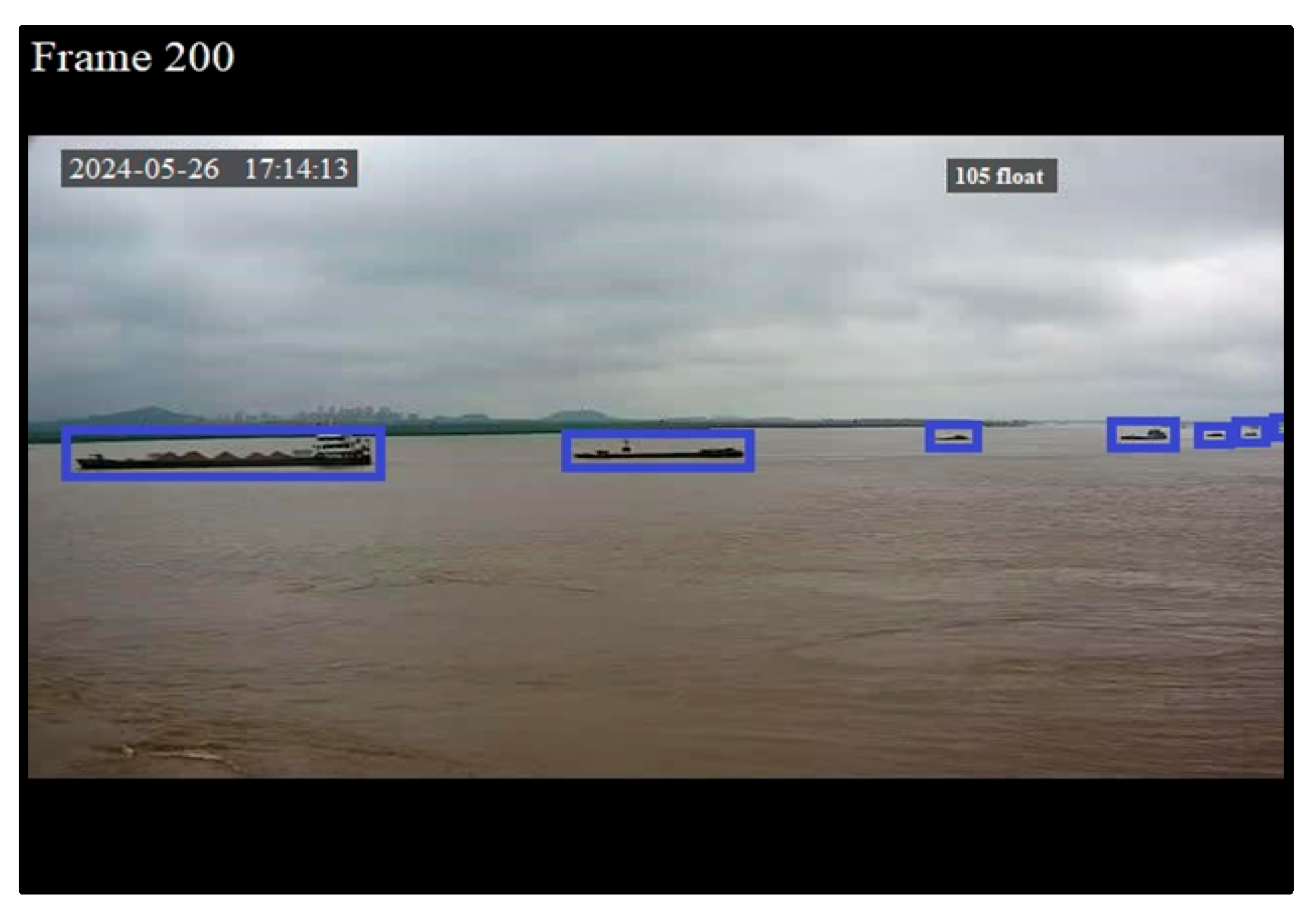
,
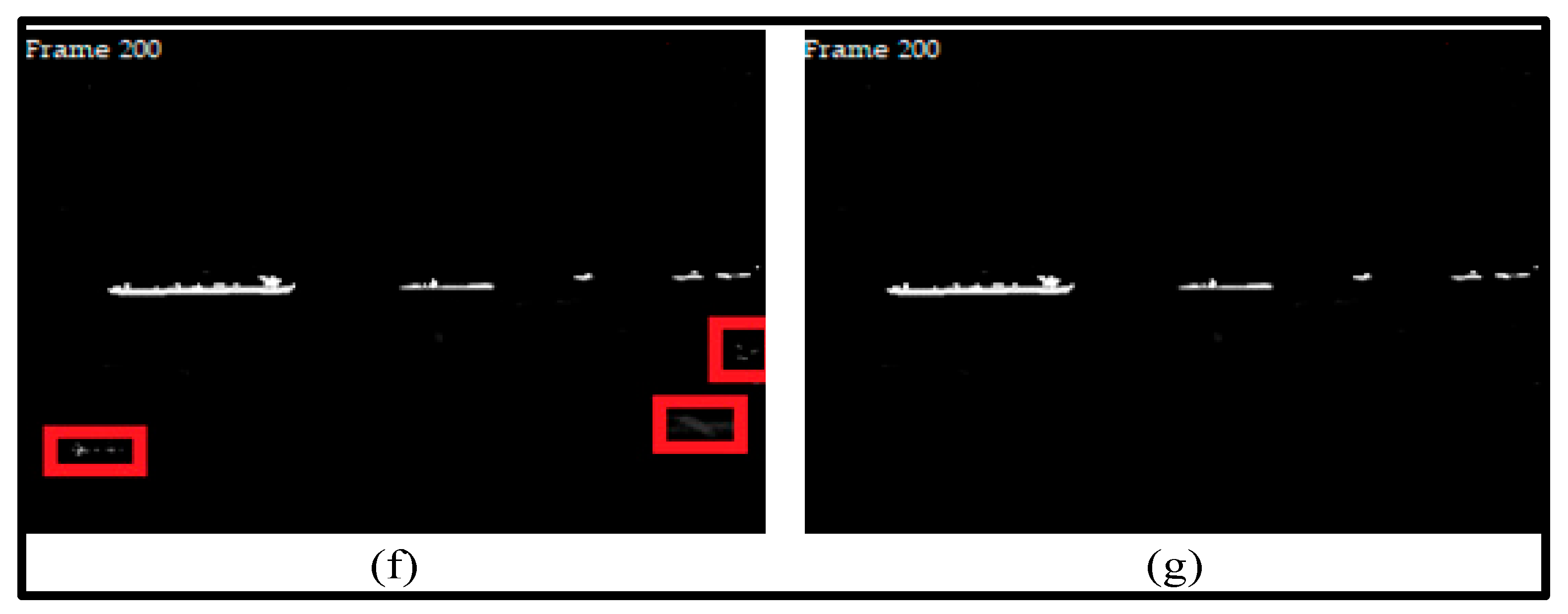
at the same time and appears in successive frames, it is identified as a vessel target. The detection results and the detected vessels are shown in
Figure 12 and
Figure 13, respectively.
It can be observed from the images that:
Figure 9(d) has more than 20 corrugated bands;
Figure 10(e) less than 10 corrugated bands;
Figure 11(f) less than 7 corrugated bands;
Figure 12(g) is free of corrugated bands. It means that corrugated bands decrease as the filtering process progresses.
Undesirable edges and protrusions in the target area of the vessel are filtered out.
The four-dimensional target feature vector is effective as it shows the contour moment feature of the vessel.
The vessel target can be distinguished from the surface clutter by setting the aspect ratio and the area width of the connected area.
The final result show us from
Figure 13 that there are seven vessels detected in this image.
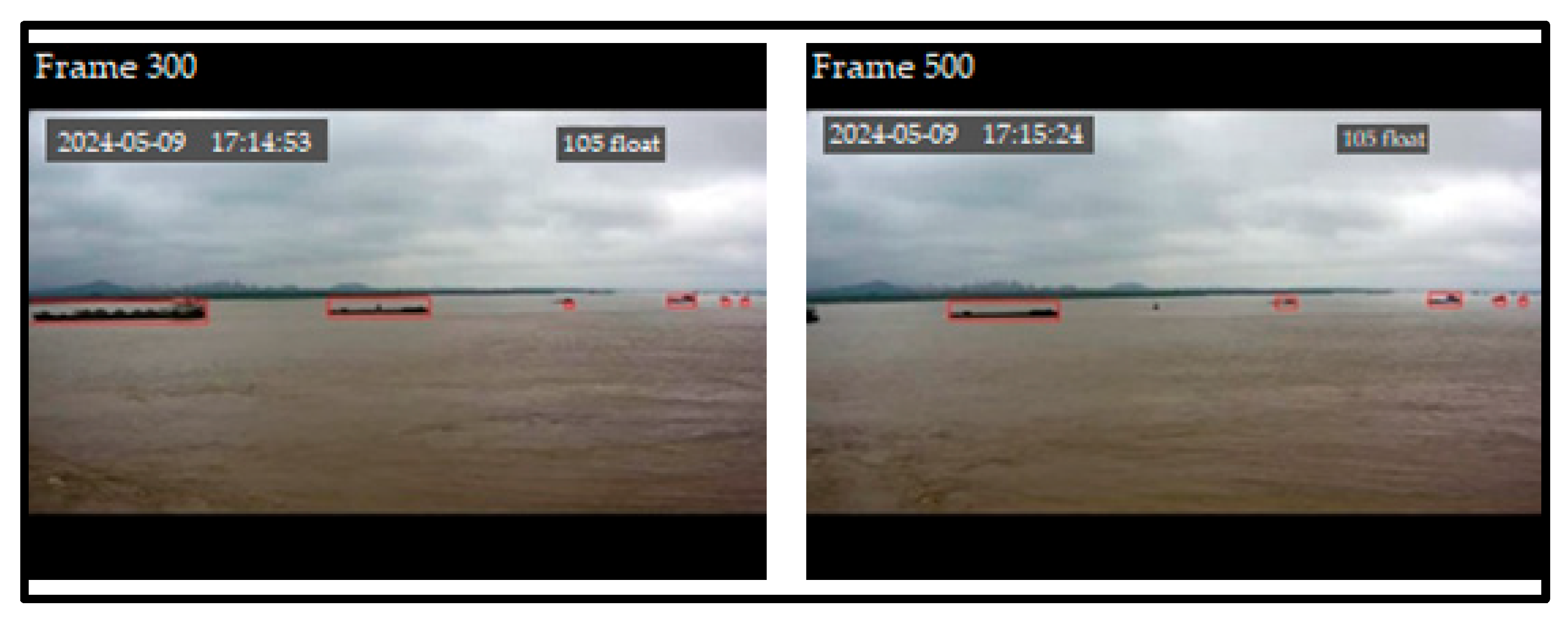
The same process is run on frames 300 and 500; the results are shown in
Figure 14; the results show that frames 300, and 500 have detected 6, and 5 vessels, respectively.
4.3. Validation of the Approach
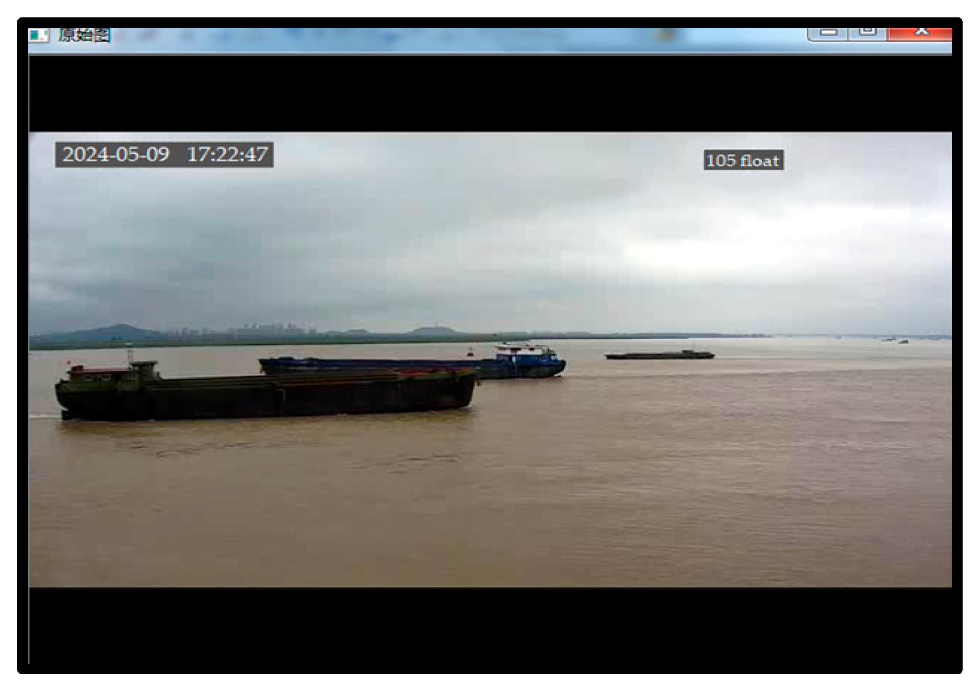
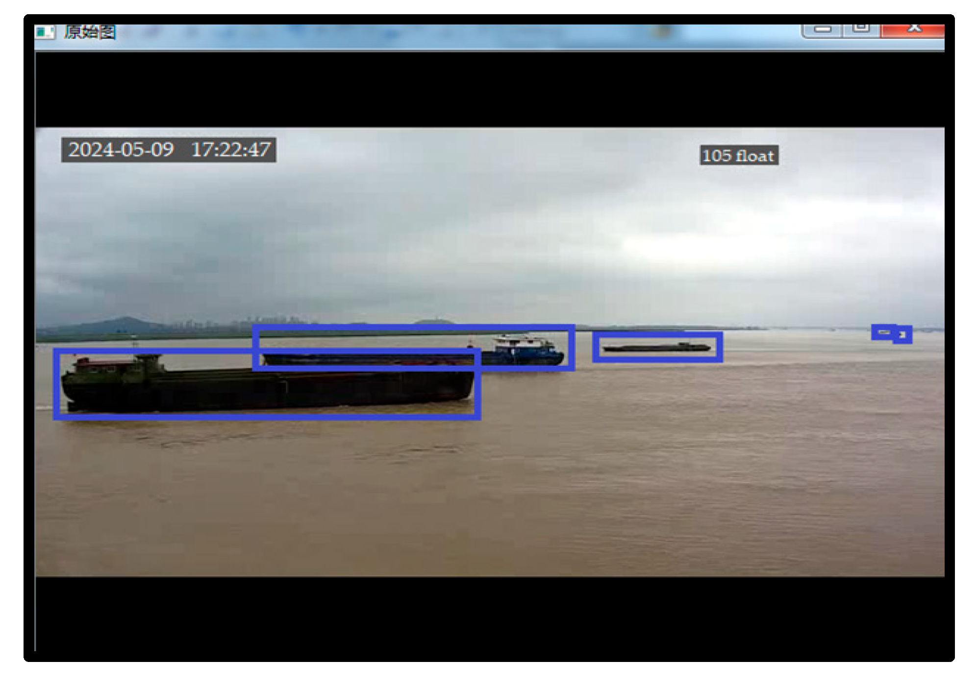
Surveillance cameras operate at the port; two video images (video 1 and video 2) were recorded at the same time late in the afternoon at about 5:20 pm. A total of 60 frames of images were continuously collected from both videos. The original video image is displayed in
Figure 15 (video 1 and video 2 have the same image).
4.3.1. First Phase
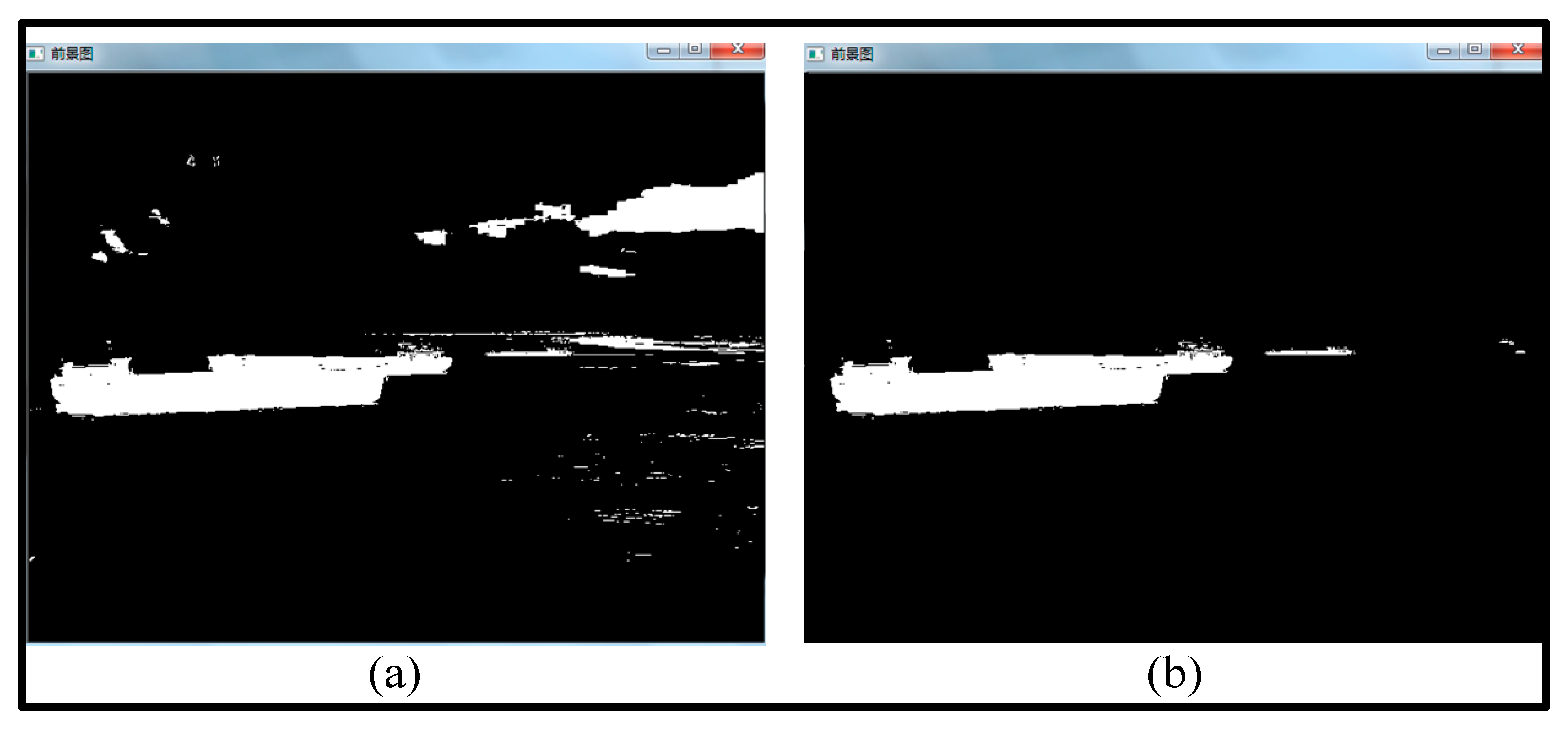
The proposed approach is performed just in video 2, and not in video 1. The processing results and the decision are shown in
Figure 16 and
Figure 17, respectively.
The recorded results of video 1 and video 2 show the following:
In
Figure 16(a), the background noise and the impulse noise are not all eliminated; while this task is well executed in
Figure 16(b). The results from video 2 are clearly better than those recorded from video 1.
In video 1, the contrast of distant vessel targets is too low, resulting in a relatively high false detection rate.
From the analysis of processing time, video 1 uses 2.37s before deciding on the number of vessels for the image. Video 2 just need 1.23s before getting the number of vessels from the image. It can be concluded that the vessel detection method adopted in this paper can meet the requirements of real-time video processing. The processing time has improved for 1.14s
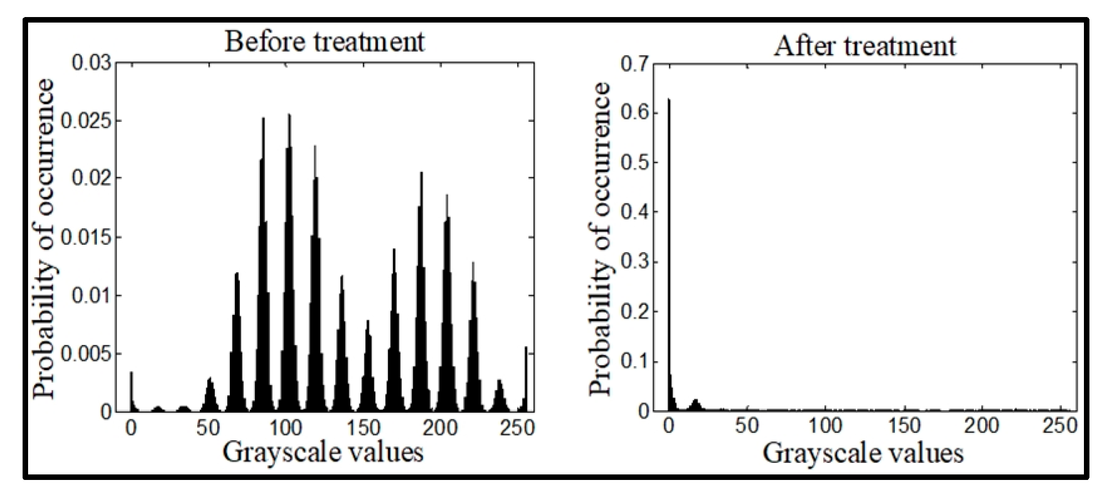
The original image and the multi-structure diagram were analyzed for significance, and the analysis results are shown in
Figure 18.
From the image, the following can be observed:
The pixels of the original image are evenly distributed in a wide range of gray levels.
After the calculations are complete, the background pixels of the sea surface are mainly concentrated in a very narrow low gray level.
The pixels corresponding to the vessel target are concentrated at the end of the high gray level, which is conducive to the image segmentation between the vessel target and the background.
Comparatively, the improved open operations perform better than traditional open operations.
4.3.2. Second Phase
Four other methods, including (M.1), (M.2), (M.3) and (M.4), were applied on the same video image to detect the vessels at the port area. (M.1) is an effective motion object detection method using optical flow estimation under a moving camera (M.1) [
50]. (M.2) is a motion detection in moving camera videos using background modeling and FlowNet [
51]. (M.3) is entitled Using Three-Frame Difference Algorithm to Detect Moving Objects [
52]. (M.4) is an approach to ship target detection based on combined optimization model of dehazing and detection [
53]. M.1 inserts a third frame between the first two to acquire the horizontal and vertical flows. The horizontal and vertical flows are then optimized through the use of the gradient function and threshold approach, respectively. Following region filling, the entire motion object boundary might be optimized using the Gaussian filtering technique to provide the final detection results. For M.2, a fusing technique for dense optical flow and background modeling method is implemented to enhance image detection outcomes. In the process, deep learning-based dense optical flow is applied along with an adaptive threshold and some post-processing techniques; this makes it possible not only to extract the moving pixels but also to increase computational cost. Regarding M.3, a three-frame difference algorithm that combines edge information is proposed to enhance moving target detection. The program uses mathematical morphology's expansion and corrosion to eliminate noise from images. For M.4, it uses a self-adaptive image dehazing module and a lightweight-improved object detection deep learning model integrated with the dehazing module, to detect the ship in the foggy image.
The aim is to assess and compare the performance of the proposed approach (IMSM) with that of the other four methods. We assess the accuracy, recall, and F-measure of detection vessels to determine the quality of each method. Matching the identified lines with the sea-truth lines is the initial stage. Let
be an image, a matching in a bipartite image is a set of edges selected so that no two edges share the same vertices. We aim to identify a matching such that, for every set of sea-truth lines
, there is no more than one detected line
, and vice versa. At present, we can determine true positive (TP), false positive (FP), and false negative (FN) in accordance with the matching of p and s. TP is defined as predicted lines
linked with sea-truth lines
. An FP is a predicted line
that does not match any sea-truthline
, while a FN is a sea-truth line that does not match any predicted line. The formula for determining Accuracy, Recall, and F-measure are:
Multiple thresholds (τ = 0.01, 0.02,..., 0.99) were applied to sea-truth and prediction pairs. As a result, we obtain a number of F-measure, accuracy, and recall scores. The performances of each method are assessed based on the results obtained from these metrics.
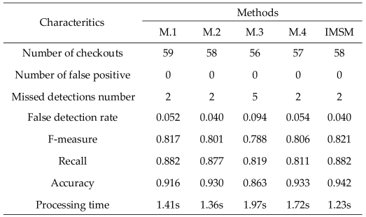
After applying each of these methods, the processing results are shown in
Table 3.
It is recorded that M.1, M.2, and IMSM output remarkable results. However, by comparing these three good approaches in depth, IMSM has the best processing time (1.23s), F-measure (0.821), and accuracy (0.94) compared to the other three methods. In addition, its false detection rate (0.04) is the lowest one. This conclusion proves the effectiveness and reliability of the proposed approach for the detection of vessels around the surveillance area. Besides, it is evident from the results in
Table 3 that edge-guided refinement, irrespective of the dataset, successfully improves detection outcomes.
5. Conclusions and Discussion
The research on the detection method of port vessels is of great practical significance to improve the efficiency of the port monitoring system. According to the characteristics of port vessels, this paper developed an improved multi-structural morphology (IMSM) approach to effectively suppress not only the background noise but also congestion interference at sea. This makes it possible to accurately detect vessels around the surveillance area in real-time. Experiments show that the proposed approach can effectively detect vessels and meet the real-time requirements of video processing. Besides, several tests were conducted with four other different methods; the results confirmed the robustness of the proposed approach in terms of detection accuracy (0.94) and processing time (1.23s).
However, the detection accuracy is not high enough; this will be even lower for smallest vessels. So, we believe that it is possible the further enhancing the proposed approach for the detection accuracy. In light of this, future work will focus on refining the structure of the proposed approach and improving its four-dimensional target feature vector ability for the location of smallest vessels. We also plan to combine our proposed approach with deep learning techniques, such as neural networking, for the identification and recognition of the smallest vessels. Doing so should increase the algorithm's overall detection accuracy.
Author Contributions
Conceptualization, B. M. Tabi Fouda and J. Atangana; methodology, B. M. Tabi Fouda; software, J. Atangana; validation, J. Atangana, H. C. Edima-Durand and W. J. Zhang; formal analysis, B. M. Tabi Fouda.; investigation, H. C. Edima-Durand; resources, W. J. Zhang; data curation, B. M. Tabi Fouda; writing—original draft preparation, B. M. Tabi Fouda; writing—review and editing, B. M. Tabi Fouda; visualization, B. M. Tabi Fouda, and H. C. Edima-Durand; supervision, W. J. Zhang, and H. C. Edima-Durand; project administration, W. J. Zhang. All authors have read and agreed to the published version of the manuscript.
Institutional Review Board Statement
the Institutional Review Board of SHANGHAI JIANQIAO UNIVERSITY and the UNIVERSITY of EBOLOWA have approved the study.
Data Availability Statement
The data used in this research work is unavailable due to ethical restrictions.
Acknowledgments
The authors would like to say thank you to the R&D Center of Intelligent Systems of Shanghai Jianqiao University, and the Electrical, Electronic and Energy Systems Laboratory of the University of Ebolowa, for the use of their equipment. Many thanks to the staff of both laboratories. We would also like to say thank you to the all workers at the port (the port of Zhangjiagang City on the East China Sea) where the data was collected for their assistance, kindness and help (the use of their materials for experiments).
Conflicts of Interest
The authors declare that they have no known competing financial interests or personal relationships that can appear to influence the work reported in this paper. The authors declare no conflicts of interest.
References
- J. H. Sundberg et al., "Seabird surveillance: combining CCTV and artificial intelligence for monitoring and research," Remote Sensing in Ecology and Conservation, vol. 9, no. 4, pp. 435-581, Aug 2023. [CrossRef]
- Xu, X.; Chen, X.; Wu, B.; Wang, Z.; Zhen, J. Exploiting high-fidelity kinematic information from port surveillance videos via a YOLO-based framework. Ocean Coast. Manag. 2022, 222. [Google Scholar] [CrossRef]
- Y. Li, and S. H. Yan, "Moving Ship Detection of Inland River Based on GNSS Reflected Signals," Conference: 2021 IEEE Specialist Meeting on Reflectometry using GNSS and other Signals of Opportunity (GNSS+R), 14-17 Sep 2021, Beijing, China, Nov. 2021.
- Song, P.; Qi, L.; Qian, X.; Lu, X. Detection of ships in inland river using high-resolution optical satellite imagery based on mixture of deformable part models. J. Parallel Distrib. Comput. 2019, 132, 1–7. [Google Scholar] [CrossRef]
- N. J. Yu, X. B. Fan, T. M. Deng, and G. T. Mao, "Ship Detection in Inland Rivers Based on Multi-Head Self-Attention," Conference: 2022 7th International Conference on Signal and Image Processing (ICSIP), 20-22 July 2022, Suzhou, China, Sep. 2022.
- J. R. A. Morillas, I. C. García, and U. Zölzer, "Ship detection based on SVM using color and texture features," Conference: 2015 IEEE International Conference on Intelligent Computer Communication and Processing (ICCP), 03-05 Sep. 2015, Cluj-Napoca, Romania: Nov 2015.
- F. Gao, and Y. G. Lu, "Moving Target Detection Using Inter-Frame Difference Methods Combined with Texture Features and Lab Color Space," Conference: 2019 International Conference on Artificial Intelligence and Advanced Manufacturing (AIAM), 16-18 Oct. 2019, Dublin, Ireland, Jan. 2020.
- Fouda, B.M.T.; Han, D.; An, B.; Chen, X.; Shen, S. Design and Implementation of Software for Ship Monitoring System in Offshore Wind Farms. Model. Simul. Eng. 2019, 2019, 1–11. [Google Scholar] [CrossRef]
- Yan, Z.; Xiao, Y.; Cheng, L.; He, R.; Ruan, X.; Zhou, X.; Li, M.; Bin, R. Exploring AIS data for intelligent maritime routes extraction. Appl. Ocean Res. 2020, 101, 102271. [Google Scholar] [CrossRef]
- Z. J. Zhong, and Q. Wang, "Research on Detection and Tracking of Moving Vehicles in Complex Environment Based on Real-Time Surveillance Video," Conference: 2020 3rd International Conference on Intelligent Robotic and Control Engineering (IRCE), 10-12 Aug. 2020, Oxford, UK, Sep. 2020.
- Wawrzyniak, N.; Hyla, T.; Popik, A. Vessel Detection and Tracking Method Based on Video Surveillance. Sensors 2019, 19, 5230. [Google Scholar] [CrossRef]
- Y. Cong, Z. Li, J. Liang, and P. Liu, "Research on video-based moving object tracking," Conference: 2023 IEEE International Conference on Mechatronics and Automation (ICMA), 06-09 Aug. 2023, Harbin, Heilongjiang, China, Aug. 2023.
- M. D. Chen et al, "MD-Alarm: A Novel Manpower Detection Method for Ship Bridge Watchkeeping Using Wi-Fi Signals," IEEE Trans. on Instr. and Meas., vol. 71, Jan. 2022.
- Deng, H.; Zhang, Y. FMR-YOLO: Infrared Ship Rotating Target Detection Based on Synthetic Fog and Multiscale Weighted Feature Fusion. IEEE Trans. Instrum. Meas. 2023, 73, 1–17. [Google Scholar] [CrossRef]
- S. Chithra and R. Roy R.U., "Otsu's Adaptive Thresholding Based Segmentation for Detection of Lung Nodules in CT Image," 2018 2nd International Conference on Trends in Electronics and Informatics (ICOEI), Tirunelveli, India, 2018, pp. 1303-1307.
- Q. D. Zhu, L. Q. Jing and R. S. Bi, "Exploration and improvement of Ostu threshold segmentation algorithm," 2010 8th World Congress on Intelligent Control and Automation, Jinan, China, 2010, pp. 6183-6188.
- Hough, P V.C.. METHOD AND MEANS FOR RECOGNIZING COMPLEX PATTERNS. United States: N. p., 1962. Web.
- Fernandes, L.A.; Oliveira, M.M. Real-time line detection through an improved Hough transform voting scheme. Pattern Recognit. 2007, 41, 299–314. [Google Scholar] [CrossRef]
- Princen, J.; Illingworth, J.; Kittler, J. A hierarchical approach to line extraction based on the Hough transform. Comput. Vision, Graph. Image Process. 1990, 52, 57–77. [Google Scholar] [CrossRef]
- Kiryati, N.; Eldar, Y.; Bruckstein, A. A probabilistic Hough transform. Pattern Recognit. 1991, 24, 303–316. [Google Scholar] [CrossRef]
- Z. Zhang, Z. Li, N. Bi, J. Zheng, J. Wang, K. Huang, W. Luo, Y. Xu, and S. Gao, "PPGnet: Learning point-pair graph for line segment detection," in IEEE Conf. Comput. Vis. Pattern Recog., May. 2019.
- K. Zhao, Q. Han, C. B. Zhang, J. Xu, and M. M. Cheng, "Deep Hough Transform for Semantic Line Detection," IEEE Transactions on Pattern Analysis and Machine Intelligence, vol. 44, no. 9, pp. 4793 - 4806, Sep. 2022.
- Akinlar, C.; Topal, C. EDLines: A real-time line segment detector with a false detection control. Pattern Recognit. Lett. 2011, 32, 1633–1642. [Google Scholar] [CrossRef]
- R. A. Lotufo, R. Audigier, A. V. Saúde, and R. C. Machado, "Morphological Image Processing," Book, Chapter Six:Microscope Image Processing (Second Edition), pp. 75-117, 2023.
- Pingel, T.J.; Clarke, K.C.; McBride, W.A. An improved simple morphological filter for the terrain classification of airborne LIDAR data. ISPRS J. Photogramm. Remote. Sens. 2013, 77, 21–30. [Google Scholar] [CrossRef]
- R. M. Thanki, and A. M. Kothari, "Morphological Image Processing," In book: Digital Image Processing using SCILAB, pp. 99-113, Jan. 2019.
- Zeng, M.; Li, J.; Peng, Z. The design of Top-Hat morphological filter and application to infrared target detection. Infrared Phys. Technol. 2005, 48, 67–76. [Google Scholar] [CrossRef]
- Z. S. Wang, F. B. Yang, Z. H. Peng, L. Chen, and L. E. Ji, "Multi-sensor image enhanced fusion algorithm based on NSST and top-hat transformation," Optik, vol. 126, no. 23, pp. 4184-4190, Dec. 2015.
- Li, Y.; Niu, Z.; Sun, Q.; Xiao, H.; Li, H. BSC-Net: Background Suppression Algorithm for Stray Lights in Star Images. Remote. Sens. 2022, 14, 4852. [Google Scholar] [CrossRef]
- M. S. Guan, H. E. Ren, and Y. Ma, "Multi-sale morphological filtering method for preserving the details of images," Control Systems Engineering, Conference: 2009 Asia-Pacific Conference on Computational Intelligence and Industrial Applications (PACIIA), 28-29 Nov. 2009, Wuhan, China, Feb. 2010.
- Chen, Z.; Chen, A.; Liu, W.; Zheng, D.; Yang, J.; Ma, X. A sea clutter suppression algorithm for over-the-horizon radar based on dictionary learning and subspace estimation. Digit. Signal Process. 2023, 140. [Google Scholar] [CrossRef]
- Appiah, O.; Asante, M.; Hayfron-Acquah, J.B. Improved approximated median filter algorithm for real-time computer vision applications. J. King Saud Univ. - Comput. Inf. Sci. 2020, 34, 782–792. [Google Scholar] [CrossRef]
- Villar, S.A.; Acosta, G.G. Median Filtering: A New Insight. J. Math. Imaging Vis. 2016, 58, 130–146. [Google Scholar] [CrossRef]
- Sahu, S.; Singh, A.K.; Ghrera, S.; Elhoseny, M. An approach for de-noising and contrast enhancement of retinal fundus image using CLAHE. Opt. Laser Technol. 2019, 110, 87–98. [Google Scholar] [CrossRef]
- H. C. Cao, N. J. Shen, and C. Qian, "An Improved Adaptive Median Filtering Algorithm Based on Star Map Denoising," CIAC 2023: Proceedings of 2023 Chinese Intelligent Automation Conference pp. 184-195, Lecture Notes in Electrical Engineering, vol 1082. Springer, Singapore.
- Li, N.; Liu, T.; Li, H. An Improved Adaptive Median Filtering Algorithm for Radar Image Co-Channel Interference Suppression. Sensors 2022, 22, 7573. [Google Scholar] [CrossRef]
- Hwang, H.; Haddad, R. Adaptive median filters: new algorithms and results. IEEE Trans. Image Process. 1995, 4, 499–502. [Google Scholar] [CrossRef]
- Yang, C.; Fang, L.; Fei, B.; Yu, Q.; Wei, H. Multi-level contour combination features for shape recognition. Comput. Vis. Image Underst. 2023, 229, 103650. [Google Scholar] [CrossRef]
- H. R. Xu, J. Y. Yang, Z. P. Shao, Y. Z. Tang, and Y. F. Li, Contour Based Shape Matching for Object Recognition. In: Kubota, N., Kiguchi, K., Liu, H., Obo, T. (eds) Intelligent Robotics and Applications. ICIRA 2016, Lecture Notes in Computer Science(), vol 9834. Springer, Cham. [CrossRef]
- Fouda, B.M.T.; Yang, B.; Han, D.; An, B. Pattern Recognition of Optical Fiber Vibration Signal of the Submarine Cable for Its Safety. IEEE Sensors J. 2020, 21, 6510–6519. [Google Scholar] [CrossRef]
- B. M. Tabi Fouda, B. Yang, D. Z. Han, and B. W. An, “Principle and Application State of Fully Distributed Fiber Optic Vibration Detection Technology Based on Φ-OTDR : A Review,” IEEE Sen. J., vol. 21, no. 15, pp. 16428-16442, Aug. 2021.
- B. M. Tabi Fouda, D. Z. Han, and B. W. An, “Pattern recognition algorithm and software design of an optical fiber vibration signal based on Φ-optical time-domain reflectometry,” Appl. Opt., vol. 58, no. 31, pp. 8423-8432, Nov. 2019.
- Marie, T.F.B.; Han, D.; An, B.; Li, J. A research on fiber-optic vibration pattern recognition based on time-frequency characteristics. Adv. Mech. Eng. 2018, 10, 1–10. [Google Scholar] [CrossRef]
- Fouda, B.M.T.; Han, D.; An, B.; Chen, X. Research and Software Design of an φ-OTDR-Based Optical Fiber Vibration Recognition Algorithm. J. Electr. Comput. Eng. 2020, 2020, 1–13. [Google Scholar] [CrossRef]
- Fouda, B.M.T.; Han, D.; An, B.; Lu, X.; Tian, Q. Events detection and recognition by the fiber vibration system based on power spectrum estimation. Adv. Mech. Eng. 2018, 10, 1–9. [Google Scholar] [CrossRef]
- B. M. Tabi Fouda, B. Yang, D. Z. Han, and B. W. An, “A Hybrid Model Integrating MPSE and IGNN for Events Recognition along Submarine Cables,” IEEE Trans. on Instr. and Meas., vol. 71, Aug. 2022.
- B. M. Tabi Fouda, D. Z. Han, B. W. An, M. Q. Pan, and X. Z. Chen, “Photoelectric Composite Cable Temperature Calculations and its Parameters Correction,” Intl. J. of Pow. Electr., vol. 15, no. 2, pp. 177-193, Mar. 2022.
- B. M. Tabi Fouda, W. J. Zhang, D. Z. Han, and B. W. An, "Research on Key Factors to Determine the Corrected Ampacity of Multicore Photoelectric Composite Cables," IEEE Sensors Journal, vol. 24, no. 6, pp. 7868-7880, Mar. 2024.
- Fouda, B.M.T.; Han, D.; Zhang, W.; An, B. Research on key technology to determine the exact maximum allowable current-carrying ampacity for submarine cables. Opt. Laser Technol. 2024, 175. [Google Scholar] [CrossRef]
- Zhang, Y.; Zheng, J.; Zhang, C.; Li, B. An effective motion object detection method using optical flow estimation under a moving camera. J. Vis. Commun. Image Represent. 2018, 55, 215–228. [Google Scholar] [CrossRef]
- D. Ibrahim, K. Irfan, K. Muhammed, and S. Feyza, "Motion detection in moving camera videos using background modeling and FlowNet," Journal of Visual Communication and Image Representation, vol. 88, 103616, Oct. 2022.
- Z. G. Zhang, H. M. Zhang, and Z. F. Zhang "Using Three-Frame Difference Algorithm to Detect Moving Objects," The International Conference on Cyber Security Intelligence and Analytics. CSIA 2019. Advances in Intelligent Systems and Computing, vol. 928, pp. 923-928. Springer, Cham. [CrossRef]
- Liu, T.; Zhang, Z.; Lei, Z.; Huo, Y.; Wang, S.; Zhao, J.; Zhang, J.; Jin, X.; Zhang, X. An approach to ship target detection based on combined optimization model of dehazing and detection. Eng. Appl. Artif. Intell. 2023, 127. [Google Scholar] [CrossRef]
Figure 1.
Navigation system architecture.
Figure 1.
Navigation system architecture.
Figure 2.
Trajectories of two independent moving targets.
Figure 2.
Trajectories of two independent moving targets.
Figure 3.
Schematic diagram of the path coherence function.
Figure 3.
Schematic diagram of the path coherence function.
Figure 4.
Flowchart of the Multi-structural morphology approach.
Figure 4.
Flowchart of the Multi-structural morphology approach.
Figure 5.
Stray noise removal process.
Figure 5.
Stray noise removal process.
Figure 6.
Structure of Hough transform. (a): Characteristics in the characteristic space (blue) accrue to a point in the parametric space (pink) called ; (b): An example of the suggested context-aware feature aggregation system.
Figure 6.
Structure of Hough transform. (a): Characteristics in the characteristic space (blue) accrue to a point in the parametric space (pink) called ; (b): An example of the suggested context-aware feature aggregation system.
Figure 7.
Results of traditional morphological filtering.
Figure 7.
Results of traditional morphological filtering.
Figure 8.
Original video image (Frame 200).
Figure 8.
Original video image (Frame 200).
Figure 9.
Images and annotations (yellow and blue lines) of DHT. For image (a) S=0.2; fir (b) S= 0.5; for (c) S= 0.8; (d) is the converted image.
Figure 9.
Images and annotations (yellow and blue lines) of DHT. For image (a) S=0.2; fir (b) S= 0.5; for (c) S= 0.8; (d) is the converted image.
Figure 10.
Results of the morphological filtering: (d) is the converted image; (e) represents the result after the usage of morphological filtering.
Figure 10.
Results of the morphological filtering: (d) is the converted image; (e) represents the result after the usage of morphological filtering.
Figure 11.
Results of the median filtering: (f) is the result after the use of median filtering.
Figure 11.
Results of the median filtering: (f) is the result after the use of median filtering.
Figure 12.
Results after application of the connected domain: (e) represents the result after application of the connected domain.
Figure 12.
Results after application of the connected domain: (e) represents the result after application of the connected domain.
Figure 13.
Decision on the outcome of the detected vessels.
Figure 13.
Decision on the outcome of the detected vessels.
Figure 14.
Sequential decision on the outcome of the detected vessels for different frames.
Figure 14.
Sequential decision on the outcome of the detected vessels for different frames.
Figure 15.
Original video frame.
Figure 15.
Original video frame.
Figure 16.
Performance results of both videos. (a) is the processing result from video 1; (b) is the processing result from video 2.
Figure 16.
Performance results of both videos. (a) is the processing result from video 1; (b) is the processing result from video 2.
Figure 17.
Decision on the result of the detected vessels.
Figure 17.
Decision on the result of the detected vessels.
Figure 18.
Significance comparison chart.
Figure 18.
Significance comparison chart.
Table 1.
Comparison of the suppression of clutter at the sea surface.
Table 1.
Comparison of the suppression of clutter at the sea surface.
Table 2.
Comparison of impulse noise suppression.
Table 2.
Comparison of impulse noise suppression.
Table 3.
Evaluation of different methods.
Table 3.
Evaluation of different methods.
|
Disclaimer/Publisher’s Note: The statements, opinions and data contained in all publications are solely those of the individual author(s) and contributor(s) and not of MDPI and/or the editor(s). MDPI and/or the editor(s) disclaim responsibility for any injury to people or property resulting from any ideas, methods, instructions or products referred to in the content. |
© 2024 by the authors. Licensee MDPI, Basel, Switzerland. This article is an open access article distributed under the terms and conditions of the Creative Commons Attribution (CC BY) license (http://creativecommons.org/licenses/by/4.0/).
