Submitted:
24 September 2024
Posted:
25 September 2024
You are already at the latest version
Abstract
The numerical algorithm used for the original multi-dimensional non-linear optimization analysis of the marine fixed pitch (screw) propulsion presented herewith, after its invention and publication has been widely used for the analysis and best fit (most probable / less uncertain) solution of over-determined non-linear mathematical problems, where the points of observations (measured data) are more than the unknown parameters in the mathematical formulation expressing the significant aspects of the observed phenomena. Any “local” attainable solution of this formidable and ingenious algorithm, may rely to the set of initial values of the unknown parameters, while not all possible solutions are expected to be physically significant for a specific problem, whereas judgment, bounds and testing are to be practiced for making sure that the attained solution is the best fit (most probable / less uncertain) one, and not necessarily the “global minimum” one. In the present paper the above algorithm is applied for the original analysis of standard ships propulsion, and particularly for the original combined application of thermo-fluid and frictional models of main engines, as well as of fixed pitch propulsion hydrodynamic models, necessary for resolving in an integrated manner the combined marine propulsion problem for standard ships under seagoing conditions.
Keywords:
seagoing
; main engines performance
; fixed pitch propeller hydrodynamics
; combined solution
1. Introduction
The numerical algorithm incorporated in the multi-dimensional non-linear optimization analysis of the marine main diesel engines performance and of the marine fixed pitch (screw) propulsion presented in this paper, has been invented during WWII, understandably earlier than its original publication on 1944 [1,2], and republication / improvement of it on 1963 [3] and 1971 [4], for resolving over-determined non-linear mathematical problems, where the number of instances of the equations (conditions) to be met are more than the number of those parameters of the mathematical formulations of the above conditions which before the application of the algorithm remain unknown. The solution attained is not an exact one as such would not be possible under the above circumstances, but instead, represents a point in the multi-dimensional domain of all unknown parameters where, all the partial derivatives of the sum of squares of the residual values of the above equations (for an exact solution, each such residual value would equal zero), summed for all above instances of the above equations (conditions), against all above unknown parameters, equal zero, meaning that any incremental change of the value of any one of the unknown parameters from the attained solution (set of values) would result to increased RMS error / uncertainty / standard deviation applicable to the attained solution, which in this regard is considered to be a, “local minimum”, best fit (most probable / less uncertain) one. Depending on how well the physical, technical or other problem is defined in the first place, and on how solid the transformation of the above definition in mathematical formulations is, the “local” attainable solution of the above algorithm, may prove to rely, or not, to the set of initial values of the unknown parameters, while not all possible solutions are expected to be physically significant for a specific problem and circumstances thereof, whereas judgment (based mainly on knowledge and experience on solving the specific problem in other ways), bounds (threshold values) on the unknown parameters fencing physical significance areas, and testing as well (restarting the above algorithm from another set of initial values for sensitivity analysis / control of the attained solution), are required for making sure that the attained solution is the most probable and less uncertain one, and not necessarily the “global minimum” one which in any case may not be the best fit solution for a particular problem and circumstances thereof [4,5,6,7,8].
The direct use to date of the above algorithm in marine applications [7,9,10,11,12,13] is mainly focused on maneuverability and neural networks for vessels steering and control, and on the respective predictions of vessels response as well, however the above algorithm and optimization analysis have been very effectively, applied for at least 40 years or more, on marine diesel engines.
In the present paper the above algorithm is applied mainly on the fixed pitch (screw) marine propulsion problem [43,44,45,46,47,48,49,50,51,52,53] and particularly for the optimization analysis of the fixed pitch (screw) ship propulsion, as well as, for the dynamic recalibration of existing and new thermo-fluid and frictional models of diesel engines [7,14,15,18,20,21,22,23,24,25,26,27,28,29,30,31,32,33,34,35,36,53], which is crucial, absolutely necessary and critical for the integrated, combined thermo-fluid / gas / hydro – dynamics (and mechanical efficiency / frictional as well) definition of the fixed pitch marine propulsion problem.
The analytical work presented below has initiated and progressed between 1986 and 2013, independently to, in parallel, between, and after as well, other research work conducted at the time (1986 – 1995, 2005 – 2008) by the author in the NTUA Internal Combustion Engines Laboratory [7,14,15,18,20,21,22,23,28,29,30], however the work completed on the subject of the present paper during the above periods could never be concluded (or even justified) without the availability and analysis of a “big data” set which could only be obtained directly from the marine environment (“at sea”). In this regard, the work presented herewith included a ~ 7 months window between August 2013 and February 2014, continued also between February and March 2015, during which detailed measurements of the above necessary “big data” set were directly obtained and analyzed over two, more than six months long in the total, voyages of the author on board ocean going vessels (oil and container carriers) actually navigating in real seagoing conditions at the South America Coastal Zone (Pacific, Atlantic, Magellan Straits), and at the Mediterranean Sea as well. Between 2020 and 2024, the above “big data” set gathered by 2015 was processed and controlled for the purposes of removing and amending any erroneous data after comparing these data against other independent data sources, as well as for validating the analytical work conducted independently by the author between 1986 and 2013 as discussed above. Furthermore during the same period (between 2020 and 2024), the above work and methodology were also reconnected, reprocessed and updated, to relevant and essential available literature [51,52,53,70,71,72,73,74,75,76,77,78,79,80,81,82,83,84,85,86,87,88,89,90,91,92,93,94,95,96,97,98,99,100,101,102,103,104,105,106,107], to international applicable standards [37,38,39,40,41,42,43,44,45,46,47,48,49,50], to relevant Regulatory / Statutory documentation [54,55,56,57,58,59,60,61,62,63,64,65,66,67,68,69], and also applied for processing other, independently acquired, data.
As discussed above, the numerical algorithm incorporated in the present multi-dimensional non-linear optimization analysis has been first published 80 years ago (1944) [1,2] and most probably invented and first applied in military (WWII) applications [1,2] even earlier than 1944. Between 1992 (32 years ago) and 1995 (29 years ago), the author of the present paper, as a member of different research teams, has first published results attained by applying the above numerical algorithm and optimization analysis on marine and other diesel engines, particularly referring to resolving in-cylinder heat transfer problems on the basis of the availability of indicated pressure diagrams [7,14,21,22,23], which is paramount for quantifying (after the end of the compression phase of the indicator diagram) the fuel injection and combustion characteristics and scale [7,14,21,22,23], for implementing First and Second Law analyses [7,14,15,21,22,23], as well as CFD models for the analysis of the gas dynamics of marine diesel engines [18,20,21,22,23], and also to determining the optimum design and feasibility of energy / oil / gas / mining wells by considering the trade-off between the cost of drilling wells as a function of the drilled depth on one hand, and the possibility of locating and exploiting energy / oil / gas / minerals in a feasible manner, as such a possibility increases with increased depth of drilling, on the other [8].
In the above instances / publications [7,14,21,22,23], explicit reference to the above numerical algorithm and optimization analysis has been made, accompanied by related references on the particular mode of numerical algorithm applied at the time, whereas the above numerical algorithm and optimization analysis work, use and application by the author, before the first attained results were reported on 1992, were already in progress since 1989. On top of this very significant, “hands – on”, direct experience gained over the last 35 years on the effective and safe application of the above numerical algorithm and optimization analysis, the current application of it comprises also the benefits of experience of others and their results reported in the meantime [9,10,11,12,13].
What makes the present approach even more interesting, and current as well, is the fact that the certain conditions mandated by some of the aforementioned applicable Regulatory / Statutory relevant frameworks [61,63] impose applicable uncertainty and materiality threshold values on measured and reported data, effectively same or equivalent to some of the ones presented and discussed in the present paper, particularly referring to the fact that the above imposed threshold values are representative of laboratory environment data flow, and as matter of fact the above measured and reported data are to be confirmed by privately legal entities (Conformity Assessment / Notified / Verification Bodies), accredited (authorized) in this regard by other, public, legal entities (National Accreditation Bodies), in the exact manner that an accredited laboratory for the analysis of physical properties, and/or the non-destructive examinations and testing of materials, or manufactured parts, or welding, should be.
2. Materials and Methods
2.0. Nomenclature
2.0.1. Latin Symbols
- Cj
- stochastic model’s calibration constant of order j, j=1,K (dimensionless)
- cor
- set of parameters utilized for the correction, alignment and benchmarking of main engines SFOC values with regard to fuel type, fuel lower calorific value and other fuel quality indexes, as well as to SFOC related environmental and other conditions in accordance with relevant industry standards and experience
- f1i
- expression of sea margin in position / timestamp pair i as function of Cj, j = 1, K
- f2i
- expression of sea running margin in position / timestamp pair i, as function of Cj, j = 1, K
- f3i
- expression of light running margin in position / timestamp pair i, as function of Cj, j = 1, K
- f4i
- expression of speed loss in position / timestamp pair i, as function of Cj, j = 1, K
- f5i
- expression of apparent TTW slip in position / timestamp pair i, as function of Cj, j = 1, K
- FOC
- fuel oil consumption, mass (kg)
- g
- acceleration of gravity (m/s2)
- I-intervals
- number of reporting intervals between daily, or other, reports
- Iobs
- number of pairs of ship’s position and timestamp of steady rotational speed
- Isfoc-obs
- number of SFOC and/or FOC to W ratio observations
- K
- number of stochastic model’s calibration constants, j=1,K
- Lobs
- number of pairs of ship’s position and timestamp of not steady rotational speed
- M
- number of thermo-fluid / frictional SFOC model’s calibration constants
- n
- shaft’s / main engine’s rotational speed (revolutions per second, RPM)
- Nrev
- number of shaft’s / engine’s revolutions
- P
- shaft’s / engine’s output power (KW)
- SFOC
- specific fuel oil consumption (kg/KJ)
- t
- time (s)
- W
- shaft’s / engine’s output mechanical work (KJ)
- Xj
- thermo-fluid / frictional SFOC model’s calibration constant of order j, j=1,M (dimensionless)
2.0.2. Greek Letters
- μ dynamic viscosity (kg/m sec)
- ν kinematic viscosity (m2/sec)
- ρ density (kg/m3)
2.0.3. Subscripts
- i
- number of observations
- intervals
- reporting intervals between daily, or other, reports
- j
- identification number of model’s calibration constant
- obs
- observations
- rev
- shaft’s / engine’s revolutions
- sfoc-obs
- SFOC, and/or FOC to W ratio, observations
2.0.4. Abbreviations
- BDN Bunker Delivery Note
- COG Course Over Ground
- DGPS Differential Global Positioning System
- ECDIS Electronic Chart Display and Information Systems,
- EEDI Energy Efficiency Design Index
- EIV Estimated Index Value
- FPP Fixed Pitch (Screw) Propeller
- FOC Fuel Oil Consumption
- MRV Monitoring, Reporting and Verifying
- NTUA National Technical University of Athens, Hellas (Greece)
- OTG Over The Ground
- RMS Root Mean Square
- ROT Rate Of Turn
- RPM Revolutions Per Minute
- SFOC Specific Fuel Oil Consumption
- SM Subject Matter
- SME Subject Matter Expert (SM Expert)
- SOG Speed Over Ground
- TTW Through The Water
- WWII World War II
2.0.5. Dimensionless Groups
- Re-h Reynolds number – hull (waterline)
- Re-p Reynolds number – propeller (diameter)
- Fr-h Froude number – hull (waterline)
- Fr-p Froude number – propeller (diameter)
- σ Propeller cavitation dimensionless number
2.1. The Fixed Pitch (Screw) Marine Propulsion Model
The fixed pitch (screw) marine propulsion model used in this study is based on the fundamental principle of the Law of Similarity and Dimensional Analysis, as applied in ship propulsion and in the form of it “applied by ships in practice” [61,63] in particular [43,51,52,53]:
“For fixed hydrostatic conditions (displacement, draft / trim), fixed water temperature and salinity, fixed air barometric pressure and any given (“quasi”-)steady vessel, water and air state and conditions, the (“quasi”-)steady state power delivered by the propeller shaft to the fixed pitch screw propeller (FPP), when such a ship is making (“quasi”-)steady course way along a fixed latitude circle, at (“quasi”-)fixed rudder angle and through sufficiently deep and otherwise unconstrained waters, depends only on the (“quasi”-)steady through the water (TTW) speed of it and the (“quasi”-)steady rotational speed of the FPP propeller” (see also Figure 1 below).
The above fixed pitch (screw) marine propulsion model is applied by means of the following multi (4) – step(s) correlation scheme, between:
- Actual seagoing, mean effective over time or instantaneous, conditions and perfectly still (calm) water and air conditions, otherwise same to the actual, mean effective or instantaneous, seagoing air and water conditions, and for the same (actual) draft and trim as well.
- Above perfectly still (calm) water and air conditions, otherwise same to the actual, mean effective or instantaneous, seagoing air and water conditions, and, ship / voyage specific “virtual” sea (power and speed) trials “ideal” conditions (perfectly calm sea, no wind, rain, snow or hail, sufficiently deep, unconstrained waters, without ice, not affecting propulsion, steady speed along the same nominal latitude circle, nominal water density, kinematic viscosity and vapour pressure values, nominal ambient air barometric pressure, temperature, humidity and density values, minimum rudder motion within a very narrow angular range around zero degrees), and for the same as above (actual) draft and trim as well.
- Above ship / voyage specific “virtual” sea (power and speed) trials at “ideal” conditions, and, the same ship’s “virtual” sea (power and speed) trials at “ideal / new vessel” conditions upon the latest delivery of the vessel by a shipyard after a new building or major modification, and for the same as above (actual) draft and trim.
- Above same ship’s “virtual” sea (power and speed) trials at “ideal / new vessel” conditions upon the latest delivery of the vessel by a shipyard after a new building or major modification, for the same as above (actual) draft and trim, and, same ship’s official sea trials corrected results, in either laden or ballast conditions (as well as, the calculated official results for the remaining, not tried, one of the two, laden or ballast, loading conditions, as / if available).
2.1.1. Correlation Scheme # 1
The above correlation is based on the following considerations:
- For ships propelled by a single FPP propeller driven by one directly coupled low speed two-stroke main diesel engine (accounting for ~ +90% of ships in service, to which the present analysis is applicable), the FPP propeller shaft revolutions divided by the respective time spent at sea when the ship is making way by its own propulsion (main engine running hours) would be equivalent to an average steady rotational speed of the FPP propeller, particularly considering the fact that such as above standard vessels are making way by keeping a steady shaft rotational speed, which is increased or decreased by as smooth as necessary ramp up and down, as near as possible linear over time, commands.
- Distance made good through the water (TTW), when the ship is making way by its own propulsion, calculated on the basis of the respective distance made over the ground (OTG) measured by (D)GPS and/or ECDIS systems, and monitored and/or confirmed on the basis of available independent distance OTG data, corrected on the basis of available speed log TTW measurements, and/or available independent data on speed and direction of water current, as well as, of heading and actual course / tracking data, divided by the respective time spent at sea during which the ship is making way by its own propulsion (main engine running hours), would be equivalent to an average TTW speed, calculated both in the forward and in the athwart ship direction.
- The fuel consumption of the main diesel engine per fuel type and BDN, divided by the respective diesel engine running hours and by the appropriate respectively applicable value of specific fuel consumption (SFOC) as well, is equivalent to the average steady engine power output, while the main engine / shaft / propeller rotational acceleration and deceleration may also be considered, or neglected, as applicable.
- Measured hydrostatic conditions (draft / trim, displacement, water density) at the start, and if possible at the end, of the voyage or leg.
- Any given sea and wind state conditions on terms of waves and wind speed and direction, air humidity, density and temperature, rain, snow or hail, resulting to the composite environmental effect on the power delivered by the shaft to the propeller.
- The aforementioned fundamental principle of the Law of Similarity and Dimensional Analysis is to be always satisfied.
2.1.2. Correlation Scheme # 2
The above correlation referring to “ideal” conditions (perfectly calm sea, no wind, rain, snow or hail, sufficiently deep, unconstrained waters, without ice, not affecting propulsion, steady speed along the same nominal latitude circle, nominal water density, viscosity and vapour pressure values, nominal ambient air barometric pressure, temperature, humidity and density values, minimum rudder motion within a very narrow angular range around zero degrees) is based on the following considerations:
- Water density changes, which for voyages in sea waters with salinity ranging from ~ 33 to 37 gr/kgr (~ 0.3% of density change) and temperature ranging from ~ 5 to 35 deg. C (~ 0.7% of density change), and/or entering / leaving inland fresh or low salinity waters from/to sea water and/or combinations thereof (within a maximum range of ~ 2.8% of density change for same temperature), may be considered for representing the actual density, salinity and temperature values.
- Water density change has also a secondary effect as, for the same voyage, or leg of it, and/or for effectively the same deadweight, water density changes will consequently cause draft changes, and draft is also a factor related to the power delivered by the propeller shaft to the propeller.
- Water kinematic viscosity also varies with salinity and temperature and relates to the dimensionless hull (waterline) and propeller Reynolds numbers which in turn have an effect on the power delivered by the propeller shaft to the screw propeller when the ship is making way, and on the frictional contributor to the shaft power in particular.
- In a similar manner, acceleration of gravity as such varies with latitude, relates to the dimensionless hull (waterline) and propeller Froude numbers which in turn have an effect on the power delivered by the propeller shaft to the screw propeller when the ship is making way, and on the dynamic contributor to the shaft power in particular, as such is discussed above.
- The distribution of the shaft power to a frictional and dynamic contributor is ship and voyage specific and mainly depends on the ship category, design and speed.
- Air barometric pressure, as well as water density and water saturated vapour pressure, as the last two vary with water temperature and salinity, acceleration of gravity as such varies with latitude, and draft as well, relate to the propeller cavitation dimensionless number σ which also has an effect to the steady state power delivered by the propeller shaft to the propeller, and on the propeller performance in particular, as such is related to the power delivered by the propeller shaft to the propeller.
- Sufficiently deep, also otherwise unconstrained, non – icy, waters will not effect to the propulsion power calculation, however shallow, or otherwise constrained, or icy waters, will result to affecting the vessel’s attainable speed.
- The ratio of the TTW speed in the athwart ship direction, to the TTW speed in the forward direction, is a direct indication of the rudder angle as such may be statically controlled for keeping a steady course against current, wind and waves of steady lateral direction and scale, and as such may have a significant speed loss effect on the vessel’s attainable TTW speed in the forward direction.
- The Rate of Turn (ROT) is also a direct indication of the rudder angle as such may be dynamically controlled for turning the vessel, or for keeping a steady course against dynamically fluctuating current’s, wind’s and waves’ direction and scale, and as such may have a significant speed loss effect on the vessel’s attainable TTW speed in the forward direction.
- The effect of the TTW acceleration / deceleration, including TTW acceleration / deceleration in the forward and in the athwart ship direction, calculated on the basis of data availability, and analysis thereof, with regard to the TTW speed in the forward and in the athwart-ship direction, Rate of Turn (ROT) and Ship's position, on the power delivered by the shaft to the propeller, may also be considered, or neglected, as applicable.
- The aforementioned fundamental principle of the Law of Similarity and Dimensional Analysis is to be always satisfied.
2.1.3. Correlation Step # 3
The above correlation is based on the consideration that the ship / voyage specific “virtual” sea trials “ideal” condition is effectively equivalent to a certain “service” condition (“service margin”) of the same ship when in “new vessel” condition upon the latest delivery of the vessel by a shipyard after a new building or a major modification, and for the same draft and trim. To this end, all the in-between the two above conditions, alternative power ratio forms / expressions (sea margin, speed loss, light running margin, sea running margin, apparent TTW slip) discussed below, shall be properly balanced to each other, on the basis of properly balanced mean effective values of particular characteristics of them (see also Figure 2 and Figure 3 below).
2.1.4. Correlation Step # 4
The above correlation is based on the consideration that the ship specific “virtual” sea trials “ideal / new vessel” condition upon the latest delivery of the vessel by a shipyard after a new building or a major modification, and for the same as above (actual) draft and trim, and the respective displacement as well, may be compiled on the basis of the same ship’s official sea trials corrected results, in either laden or ballast conditions (as well as, of the calculated official results for the remaining, not tried, one of the two, laden or ballast, loading conditions, as / if available). To this end, all the in-between the above conditions, alternative power ratio forms / expressions (sea margin, speed loss, light running margin, sea running margin, apparent TTW slip) discussed below, shall be as per the above, properly balanced to each other, on the basis of properly balanced mean effective values of particular characteristics of the above conditions, particularly referring to draft, trim and displacement, as applicable (see also Figure 3 below).
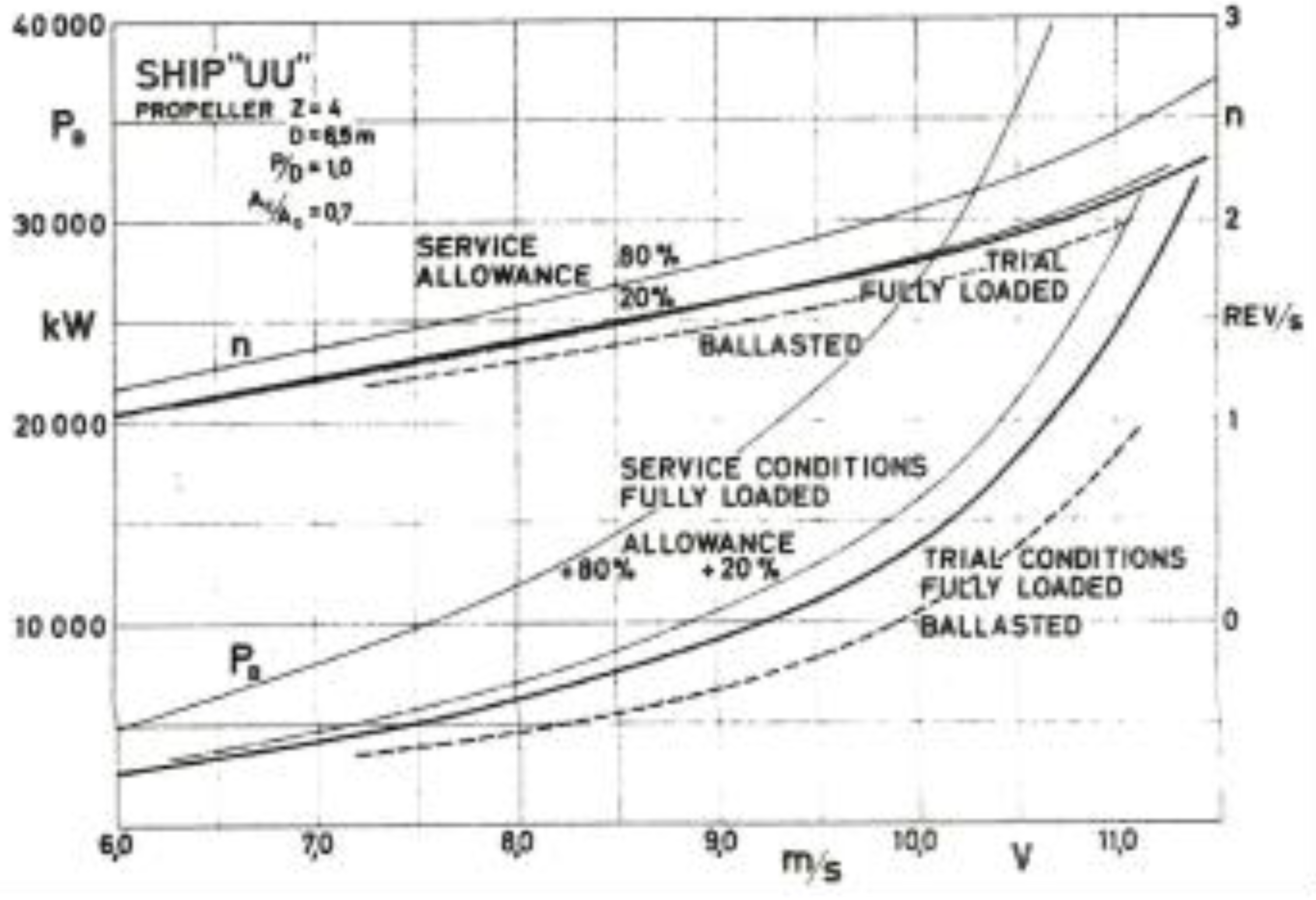
Figure 3.
“Ps”: (“quasi”-) steady state power delivered by the propeller shaft to the fixed pitch screw propeller (FPP), as a function of the (“quasi”-) steady TTW speed, a) at sea trials “ideal” condition upon the latest delivery of a vessel by a shipyard after a new building or a major modification and at fully laden conditions, b) same as a) above, however at ballast conditions, c) at the same vessel’s “virtual sea trials” (“ideal”), voyage specific “service” condition (“service margin”) of +20% (power for sustaining the same, “new building or major modification”, ideal conditions TTW speed), and d) at the same vessel’s “virtual sea trials” (“ideal”), voyage specific, “service” condition (“service margin”) of +80% (power for sustaining the same, “new building or major modification”, ideal conditions TTW speed), as well as, “n”: (“quasi”-) steady rotational speed of the FPP propeller, as a function of the (“quasi”-) steady TTW speed at the same conditions a), b), c) and d) above.
2.1.5. Service Conditions Alternative Ratios / Indexes (Sea Margin, Speed Loss, Light Running Margin, Sea Running Margin, Apparent TTW Slip)
On the basis of the combined correlation steps #1 and #2 above, the effect of any given steady sea and wind state conditions (wave and/or ice, water density, water saturated vapour pressure and kinematic viscosity, wind speed / direction, rain, snow or hail, ambient air barometric pressure, humidity, density and temperature), rudder angle and motion and latitude change, shallow, and/or otherwise constrained, and/or icy waters, vessel’s and/or main engine / shaft / propeller accelerating / decelerating conditions, is defined as the ratio between the shaft power delivered to the FPP propeller under the above conditions, to the shaft power delivered to the FPP propeller in “ideal” conditions (perfectly calm sea, no wind, rain, snow or hail, unconstrained, sufficiently deep, waters, without ice, not affecting propulsion, steady speed along same nominal latitude circle, nominal water density, kinematic viscosity and vapour pressure values, air nominal barometric pressure, temperature, density and humidity values, minimum rudder motion within a very narrow angular range around zero degrees), and for the same draft and trim as well, while the above ratio may be comprehensively defined on the basis of all the above actual, other than ideal, conditions available data, and is representative / indicative of the composite effective result of all the above actual, other than ideal, conditions, for any given value of the shaft power delivered to the FPP propeller.
The above ratio, in any one of its following alternative forms / expressions (sea margin, speed loss, light running margin, sea running margin), effectively compares and quantifies any given actual, mean effective or instantaneous, seagoing conditions against the ship / voyage specific “virtual” sea (power and speed) trials at “ideal” conditions:
- The above shaft power ratio, when considered for sustaining the same “ideal” conditions TTW speed, decreased by one (or by 100% in case it is calculated as a percentage), is defined as the sea margin.
- The above shaft power ratio, when considered for sustaining the same “ideal” conditions shaft rotational speed, decreased by one (or by 100% in case it is calculated as a percentage), is defined as the sea running margin.
- The light running margin is defined as the reduction percentage (%) of the “ideal” conditions shaft rotational speed necessary for delivering the same “ideal” shaft power to the FPP propeller, which is common for, and representative of, steady (fixed) sea margin and/or sea running margin values, for any given value of the shaft power delivered to the FPP propeller.
- The speed loss is defined as the reduction (%) of the “ideal” conditions TTW speed necessary for delivering the same “ideal” shaft power to the FPP propeller under the above actual conditions, and is common for, and representative of, steady (fixed) sea margin and/or sea running margin values, for any given value of the shaft power delivered to the FPP propeller.
- The above dimensionless indexes (sea margin, sea running margin, light running margin and speed loss) are all interrelated to each other, meaning that when one of them is determined, then the other three are determined as well, while each one and all of them may be comprehensively defined on the basis of all the above actual, other than ideal, conditions available data.
- One minus the dimensionless apparent TTW slip, stands as a ship specific dimensionless ratio of the TTW speed in the forward direction to the FPP rotational speed, and as such, depends mainly to any and all of the above dimensionless indexes (sea margin, sea running margin, light running margin and speed loss), and slightly only, to a proper dimensionless form of the FPP rotational speed.
The specific voyage’s / ship’s “ideal” conditions are generally expected to be different to the official “ideal / new vessel” conditions as such may be compiled for the specific voyage’s hydrostatic conditions on the basis of the corrected results of the official sea (speed and power) trials conducted upon the delivery of the vessel by the shipyard after a new building or a major modification, the reason being the change of the geometry, wetted surface and roughness condition of the hull, the rudder, the propeller and the appendages thereof, due to sea-keeping, as well as the permanent, or not, effect of loading distribution, all the above accounting for the so called “service margin” in contrast to the sea margin as defined under point a above. Same or similar are applicable for the main engine and the shaft line and stern tube as well.
With regard to the above, reference is also made to Figure 1 above, indicating in the system of axes of the propeller rotational speed .vs. the shaft power delivered to the FPP propeller, 3 sets of curves:
- g.
- the steady (fixed) through the water (TTW) speed in the forward direction set of curves as such can be visualized in Figure 1 above (e.g., 13, 16, 19 and 22 knots),
- h.
- the steady (fixed) apparent TTW slip set of curves as such can be visualized in Figure 1 above (e.g., -2%, 2%, 6% and 10%), and,
- i.
- the steady (fixed) light running margin (also steady / fixed sea margin, sea running margin and speed loss) set of curves as such can be visualized in Figure 1 above (e.g., light running margin of A: 0%, B: 3% and C: 6%, in green, blue and red colours).
Each one of, and all, service conditions dimensionless indexes (sea margin, sea running margin, light running margin, speed loss and apparent TTW slip) discussed above, are interrelated to each other, meaning that when one of them is determined, then the other four are determined as well), and may be comprehensively defined on the basis of the continuous availability of all the above actual, other than ideal, conditions as such can be derived from an available “big data” set. The above comprehensive definition comprises two components / sub-models, as per the four correlation steps above:
- j.
- A deterministic one.
- k.
- A hybrid, stochastic / deterministic, optimization one.
The optimization procedure applicable for the hybrid stochastic / deterministic model applied as per the correlation steps above is based on:
- l.
- The fact that the rotational acceleration of the main engine / shaft / propeller of a standard vessel, during the greatest part of all voyages, is zero (steady rotational speed), while for the remaining, significantly shorter, time intervals of all voyages, is instead, steady or as smooth and as near to steady as well, as possible.
- m.
- The fundamental principle of the Law of Similarity and Dimensional Analysis as applied in Ship Propulsion in particular.
On the basis of the above optimization procedure the above service conditions dimensionless indexes may be defined throughout all voyages of each vessel, and in conjunction with the deterministic component / model as per the correlation steps above, the instantaneous (and average) FPP propeller’s and engine’s rotational speed n (RPM) and power P (KW) may be predicted on the basis of the following two considerations:
- n.
- The “big data” set is used for calculating average and instantaneous values of the vessel’s TTW speed in the forward direction.
- o.
- Considering that the “correct” values of all the aforementioned stochastic model’s calibration constants are not known before the start of the optimization process, independent ship tracking, and environmental (meteorological / oceanographic, actual or “hind-cast”) as well, data may be used, in conjunction with the above, far more quantitatively significant, deterministic model for defining average and instantaneous values of any, and all, of the service conditions dimensionless indexes (sea margin, sea running margin, light running margin, speed loss and apparent TTW slip) over time and position discussed above, as functions of the aforementioned unknown stochastic model’s calibration constants only:
(sea margin)i = f1i(Cj, j = 1, K) , i = 1, Iobs + Lobs
(sea running margin)i = f2i(Cj, j = 1,K), i=1, Iobs + Lobs
(light running margin)i = f3i(Cj, j = 1,K), i=1, Iobs + Lobs
(speed loss)i = f4i(Cj, j=1, K), i = 1, Iobs + Lobs
(apparent TTW slip)i = f5i(Cj, j=1, K), i=1, Iobs + Lobs
By combining the above two considerations, the instantaneous (and average) FPP propeller’s and engine’s rotational speed n (RPM) and power P (KW) may be defined on the sole basis of the unknown aforementioned stochastic model’s, K, calibration constants, Cj, j =1, K, all along the vessel’s course as such is precisely defined on the basis of all of the observed pairs of positions and UTC timestamps Iobs + Lobs, i = 1, Iobs + Lobs:
Pi = Pi(Cj, j = 1, K) , i = 1, Iobs + Lobs
ni = ni(Cj, j = 1, K) , i = 1, Iobs + Lobs
Considering furthermore that the FPP propeller’s and engine’s rotational speed (RPM) is actually regulated by the main engine’s “governor” (control and safety system) by controlling through the main engine’s fuel system the engine’s fuel consumption for keeping the rotational acceleration of the main engine and FPP propeller of a standard vessel, during the greatest part of all voyages, equal to zero (steady rotational speed set-point values), while for the remaining, significantly shorter, time intervals of all voyages, keeping the rotational acceleration steady, or as smooth, and as near to steady as well, as possible, the following conditions should be always met at the following 2 different sets of AIS observed, and/or calculated, pairs of positions and UTC timestamps:
- p.
- Iobs, where the rotational acceleration of the main engine and FPP propeller is zero (steady rotational speed, ni = ni(Cj, j = 1, K), i =1, Iobs, or, dni(Cj, j = 1, K)/dt = 0):
- q.
- Lobs, where the rotational acceleration of the main engine and FPP propeller (rotational acceleration, dni/dt = dni(Cj, j = 1, K)/dt, i =1, Lobs) is steady, or as smooth, and as near to steady, as possible (d2ni(Cj, j = 1, K)/dt2 = ~ 0, i =1, Lobs):
- r.
- the above over-determined mathematical problem can only be solved as a least squares optimization (stochastic) problem;
- s.
- the uncertainty induced due to the aggregate error RMS (residual least squares RMS / standard deviation of the measured data) inherent in the above optimization process itself, is expected to be as minimal as possible.
In cases where credible and reliable data of main engine / shaft / propeller revolutions per voyage, or for a number of consequent voyages, or per day, Nrev, are reported, the above analysis, may be applied by also meeting the following additional condition(s), which is (are) to be met for each discrete voyage, or for a number of consequent voyages, or per day, for which Nrev is known (reported), however this is not necessarily required as a minimum:
(each one of) the above equation(s) applied for each one of all, K, model calibration constants Cj, j =1, K, including voyage specific and reporting period specific model calibration constants while the integral is to be calculated on the basis of all of the observed pairs of positions and UTC timestamps Iobs + Lobs, i = 1, Iobs + Lobs, whereas in cases of credible and reliable data of main engine / shaft / FPP propeller revolutions reported daily, and/or between other reports of sufficiently high frequency (number) during the same voyage, meeting the condition set by equation (10) above between all subsequent reports is effectively equivalent to resolving the same problem, without necessarily meeting the previously set conditions:
and/or:
dni(Cj, j = 1, K)/dt = 0, i =1, Iobs
d2ni(Cj, j = 1, K)/dt2 = ~ 0, i =1, Lobs
In the same manner as above, in cases where credible and reliable data of main engine output of mechanical work per voyage, or for a number of consequent voyages, or per day, W, are reported, the above analysis, may be applied by also meeting the following additional condition(s), which is (are) to be met for each discrete voyage, or for a number of consequent voyages, or per day, for which W is known (reported), however this is not necessarily required as a minimum:
(each one of) the above equation(s) applied for each one of all, K, model calibration constants Cj, j =1, K, including voyage specific and reporting period specific model calibration constants while the integral is to be calculated on the basis of all of the observed pairs of positions and UTC timestamps Iobs + Lobs, i = 1, Iobs + Lobs, whereas in cases of credible and reliable data of main engine / shaft / FPP propeller power reported daily, and/or between other reports of sufficiently high frequency (number) during the same voyage, meeting the condition set by equation (13) above is also effectively equivalent to resolving the same problem, without necessarily meeting the previously conditions set by equations (11) and/or (12) above.
In the same manner as above, in cases where credible and reliable data of main engine fuel oil consumption per voyage, or for a number of consequent voyages, or per day, FOC, are reported, the above analysis, may be applied by also meeting the following additional condition(s), which is (are) to be met for each discrete voyage, or for a number of consequent voyages, or per day, for which FOC is known (reported), however in any case, this is not necessarily required as a minimum:
(each one of) the above equation(s) applied for each one of all, K, model calibration constants Cj, j =1, K, including voyage specific and reporting period specific model calibration constants while the integral is to be calculated on the basis of all of the observed pairs of positions and UTC timestamps Iobs + Lobs, i = 1, Iobs + Lobs, whereas in cases of credible and reliable data of main engine fuel oil consumption per voyage reported daily, and/or between other reports of sufficiently high frequency (number) during the same voyage, meeting the condition set by equation (14) above is also effectively equivalent to resolving the same problem, without necessarily meeting the previously conditions set by equations (11) and/or (12) above.
Considering all the above and provided that one or more of equations (10), (13) and (14) above may be applied, solving the problem described above without necessarily meeting the conditions previously set by equations (11) and/or (12) above, is equivalent to considering that the trinities of the following reported data obtained over a number of reporting intervals, i = 1, I-intervals, after being controlled for the purpose of identifying and removing / amending / rectifying any material misstatements [61,63], possibly inherent in them when in raw condition:
- A.
- main engine fuel consumption, FOC, and/or main engine output / shaft mechanical work, W, over a time spent at sea interval during which the ship is under its own propulsion (main engine running hours interval),
- B.
- distance TTW in the forward direction over the same as above time spent at sea interval during which the ship is under its own propulsion (main engine running hours interval), and,
- C.
- FPP propeller revolutions, Nrev, over the same as above time spent at sea interval during which the ship is under its own propulsion (main engine running hours interval),
will follow a certain pattern in accordance with the above fundamental principle of the Law of Similarity and Dimensional Analysis (see also Figure 1 below), meaning that when any two of the three, A, B and C above, are determined, then the third one is to be determined as well, and to this end the optimization problem to be resolved is equivalent to the quantitative determination of the “best fitted” / “mean” / “most probable” [61,63] pattern (function / curves set) of minimum (effectively “zero”) error (“uncertainty”) [61,63] for correlating any two of the above data A, B and C above, to the third one, which can be established as per the above, in the following manner:
and/or:
and/or:
each one of the above equations applied for each one of all, K, model calibration constants Cj, j =1, K, including voyage specific and reporting period specific model calibration constants.
Or in other words, and as far as the correlation of propeller shaft RPM and power to TTW (log) speed data by “ships in practice” [61,63] is concerned:
- t.
- The trinities of TTW (log) speed, propeller shaft RPM and power average data values, during each different voyage’s, daily or other, reporting periods / intervals, are expected to be correlated in a certain predetermined pattern (“trend”), whereas their correlation is to compare in a technically and physically meaningful manner to the specific main engine and propeller data, and to similar main engines and propellers in general (see also Figure 1, Figure 2 and Figure 3 above). This is not examined by simply comparing statically the reported shaft power values with the calculated ones, but instead by recalibrating / reconnecting the hydrodynamic models applicable for the above correlation, with the respective actual data, for achieving a best fit match between the reported and the calculated values of shaft power, which is equivalent to determining the most probable shaft power model definition of least uncertainty which will produce a, physically / technically significant and consistent, “mean” value (“of reasonable degree of certainty”) [61,63] of shaft power for all applicable (reported) combinations of RPM and TTW (log) speed data values.
With regard to the unknown ship (not voyage) specific function:
this is determined by evaluating the “best fit” / “most probable” / “less uncertain” [61,63] set of values for a number of unknown calibration constants of the applicable composite thermo-fluid and frictional SFOC model, Xj, j=1,M, based on respective diesel engines models already in place [7,14,15,16,17,19,20,21,22,23,24,25,26,29,31,32,36], specifically extended for covering also two stroke main engines layout and operation thereof, for matching the shop tests, and/or bollard tests, and/or sea trials results, and/or actual operational, observed data points i=1, Isfoc-obs for marine diesel engines SFOC values, as / if available / applicable:
and/or:
each one of the above equations applied for each one of all, M, calibration constants of the applicable composite thermo-fluid and frictional SFOC model, Xj, j=1,M.
SFOC = SFOC(Pi,ni,dni/dt,cor) = SFOC(Pi,ni,dni/dt,cor,Xj,j=1,M)
With regard to the above, particular attention is to be paid to, cor, the set of parameters to be utilized for the correction, alignment and benchmarking of main engines SFOC values with regard to fuel type, fuel lower calorific value and other fuel quality indexes, as well as to SFOC related environmental and other conditions in accordance with relevant industry standards and experience. The above set of parameters is expected not to be unknown, meaning that the respectively applicable fuel quality data and matching environmental conditions are, ideally, expected to be known in advance (see also following subsection on “Big data” set). SFOC is inversely proportional to the effective overall efficiency, which in turn is equal to the respective product of (mechanical efficiency) times (indicated efficiency), while an effective overall efficiency value of ~ 0.50, for an MDO/MGO net energy – lower calorific value reference value of 42.7 MJ/kgr, would be equivalent to a SFOC value of ~ 168 gr / KW hr.
In summary, and as far as the correlation of main engine SFOC, RPM and power data by “ships in practice” [61,63] is concerned:
- u.
- The trinities of SFOC, RPM and power average data values of the main engine are expected to be correlated in a certain predetermined pattern (“trend”), whereas the SFOC values are to compare in a technically and physically meaningful manner to the shop test SFOC values (curve) of the specific main engine, and of similar main engines in general. This is not examined by simply comparing statically the reported SFOC values with the calculated ones, but instead by recalibrating / reconnecting dynamic models for main engines’ mechanical efficiency and indicated efficiency (on terms of relevant thermodynamics, heat transfer and gas dynamics analyses) as well, with the respective actual engine data, for achieving a best fit / match between the reported and the calculated values of SFOC, which is equivalent to determining the most probable SFOC model definition of least uncertainty which will produce a, physically / technically significant and consistent, “mean” value (“of reasonable degree of certainty”) [61,63] of SFOC for all applicable (reported) combinations of RPM and power data values.
2.2. “Big Data” Set
The “big data” set required for implementing the above fixed pitch (screw) marine propulsion model as per equations (1) to (20) as / if applicable, comprises two distinct types of data:
- Ship tracking data (AIS, LRIT, other)
- Environmental, “met-ocean” (meteorological and oceanographic), “hind-cast” or actual, data
2.2.1. Ship Tracking Data (AIS, LRIT, Other)
The AIS, or other ship tracking, data include the following:
- IMO Number and Type of ship.
- Ship's position (longitude and latitude in decimal degrees) with accuracy indication and integrity status: Automatically updated from the position sensor connected to AIS. The accuracy indication is approximately 10 m.
- Position Time stamp in UTC (date; hour; minute; second; 24 hours format YYYY/MM/DD HH:mm:ss: Automatically updated from ship's main position sensor connected to AIS.
- Course over ground (COG, ° -180 to 180 Northbound, 0 to 360 Southbound): Automatically updated from ship's main position sensor connected to AIS, if that sensor calculates COG. This information might not be available.
- Speed over ground (SOG, knots): Automatically updated from the position sensor connected to AIS. This information might not be available.
- Heading (°-180 to 180 Northbound, °0 to 360 Southbound): Automatically updated from the ship's heading sensor connected to AIS.
-
Navigational status: To be manually entered by the OOW and changed as necessary:
- underway by engines;
- at anchor;
- not under command (NUC);
- restricted in ability to maneuver (RIATM);
- moored;
- constrained by draught;
- aground;
- underway by sail.
- Rate of turn, or (ROT, ° per minute): Automatically updated from the ship's ROT sensor or derived from the gyro. This information might not be available.
- Draft (Ship's draught, m): To be manually entered at the start of the voyage using the maximum draft for the voyage and amended as required (e.g. – result of de-ballasting prior to port entry).
- Destination: To be manually entered at the start of the voyage and kept up to date as necessary.
- ETA (date; hour; minute; second; UTC 24 hours format): To be manually entered at the start of the voyage and kept up to date as necessary.
The AIS data included in the relevant “big data” set:
- l.
- Are transmitted by ships at predefined frequencies related to the navigational status, speed and rate of turn (ROT), thereof.
- m.
- Are received and made available at subsets of lesser, varying, frequencies depending on actual circumstances and capabilities, by other ships, satellite stations and terrestrial stations.
- n.
- Although it would be really “nice”, apparently, there is not one, universal system receiving and storing all AIS data, of all ships, at all frequencies.
All the above are relevant to universal ship tracking data, however same as above, and/or more, relevant data are, not universally, available by means of own vessel’s shipboard systems.
2.2.2. Environmental, “Met-Ocean” (Meteorological and Oceanographic), “Hind-Cast” or Actual, Data
The environmental “met-ocean” (meteorological and oceanographic), “hind-cast” or actual historical, data include the following:
- Barometric Air Pressure (mbar): At AIS Ship's position, AIS Position Time stamp in UTC and sea surface level.
- Air Temperature (° C): At AIS Ship's position, AIS Position Time stamp in UTC and sea surface level.
- Air Relative Humidity (%): At AIS Ship's position, AIS Position Time stamp in UTC and sea surface level.
- Air Density (kgr/m3): At AIS Ship's position, AIS Position Time stamp in UTC and sea surface level.
- Wind Speed (m/s): At AIS Ship's position, AIS Position Time stamp in UTC and sea surface level.
- Wind Direction (°):At AIS Ship's position, AIS Position Time stamp in UTC and sea surface level.
- Rain, Snow, or Hail Data: At AIS Ship's position, AIS Position Time stamp in UTC and sea surface level.
- Water Depth (m): At AIS Ship’s position (sufficiently deep unconstrained waters needed not be reported / tracked in detail, while the non – availability of depth data would denote an erroneous position ashore).
- Water Salinity (gr/kgr): Average value between surface (zero depth) and depth equal to AIS Ship's draught, at AIS Ship's position and AIS Position Time stamp in UTC.
- Water Temperature (° C): Average value between surface (zero depth) and depth equal to AIS Ship's draught, at AIS Ship's position and AIS Position Time stamp in UTC.
- Water Density (kgr/m3): Average value between surface (zero depth) and depth equal to AIS Ship's draught, at AIS Ship's position and AIS Position Time stamp in UTC.
- Water Kinematic Viscosity (m2/s): Average value between surface (zero depth) and depth equal to AIS Ship's draught, at AIS Ship's position and AIS Position Time stamp in UTC.
- Water Saturated Vapor Pressure (mbar): Average value between surface (zero depth) and depth equal to AIS Ship's draught, at AIS Ship's position and AIS Position Time stamp in UTC.
- Ice in Water Data: Average value between surface (zero depth) and depth equal to AIS Ship's draught, at AIS Ship's position and AIS Position Time stamp in UTC:
- Water Current Speed (m/s): Average value between surface (zero depth) and depth equal to AIS Ship's draught, at AIS Ship's position and AIS Position Time stamp in UTC.
- Water Current Direction (°): Average value between surface (zero depth) and depth equal to AIS Ship's draught, at AIS Ship's position and AIS Position Time stamp in UTC.
- Wave Data: At AIS Ship's position, AIS Position Time stamp in UTC and sea surface level.
All of the above are relevant to universal shop data systems, however some of the above data are, not universally, also available by means of own vessel’s shipboard systems.
2.3. Uncertainty and Materiality Definitions
2.3.1. Uncertainty Definition
Uncertainty is defined, and actually regulated [61], as a parameter, associated with the result of the determination of a quantity, that characterizes the dispersion of the values that could reasonably be attributed to the particular quantity, including the effects of systematic as well as of random factors, expressed as a percentage, and describes a confidence interval around the mean value comprising 95 % of inferred values taking into account any asymmetry of the distribution of values [61]. In the above context, an uncertainty default value in line with industry standards, and as far as FOC on ship specific / voyage (leg) specific basis is concerned, is 10%.
2.3.2. Materiality Definition
Materiality level is defined, and actually regulated [63], as the quantitative threshold or cut-off point above which any erroneous entries inherent in the acquired data, individually or taken together, are considered to be material [63]. The above materiality level as far as FOC on an annual, ship specific, reporting basis is concerned, is regulated to 5% [63].
3. Results
The results of the original analysis introduced in the previous sections, which are presented in this paper, are based in data acquired from 10 vessels equipped with auto-logging / data acquisition / “machine learning” (ML) embedded Hardware In the Loop (HIL) shipboard systems, for acquiring, logging and analyzing / controlling data in real time via high end embedded Field-Programmable Gate Arrays (FPGA) controllers fit for the above purpose.
The aforementioned shipboard systems are capable of validating vessel sensors, monitoring data flow and rectifying data gaps, all the above in real time. These systems’ software runs directly on FPGA chips, independent from any operating system software, for eliminating any vulnerability inherent to operating systems. The data sets generated by these shipboard systems are based on real-time measurements from sensors located in different parts of the aforementioned vessels. Running system software code directly on an FPGA chip is a (computing wise) “low level” process essentially different to the processes of contemporary (effectively, “personal”) computing / operating systems which have been originally developed for optimizing (essentially, maximizing the effectiveness of) human – to – computer interaction. Field Programmable Gate Arrays (FPGAs) are developed for being capable to provide “time deterministic” / “clocked” / accurately “time stamped” data acquisition on the basis of their architecture which, among other features, comprises multiple I/O channels / blocks effectively operating / “clocked” in parallel, without necessarily utilizing shared internal resources, including but not limited to a single CPU time / availability, and without applying as well operating system interrupts scanning (effectively, low frequency sampling) at the effective frequency which is typical / standard for sharing (effectively, “personal”) computing resources, including data acquisition devices scanning by system’s CPU. In this regard FPGA based shipboard systems offer the best possible circumstances, tools and possibilities for managing any issues caused by other shipboard data acquisition systems, individual sensors’ processors / processing systems and buffers thereof, as well as by irregular pulse operation of flow meters or other sensors. As a matter of fact, FPGA based shipboard systems’ high frequency (effectively, continuous) data acquisition sampling is the exact reason for their real-time, remarkably high, data accuracy and quality, as well as for their capability of automated rectification of data gaps.
The “big data” sets discussed above has been initially acquired by the aforementioned shipboard systems, and subsequently (before the analysis presented in the previous sections is applied and the analysis results presented below are generated) have been also confirmed, validated and/or supplemented, by respective data acquired by means of universal systems such as the ones discussed under section 2.2 above.
The aforementioned vessels’ main engines specifics are presented in Table 1 below:
During the discussed data acquisition period each one of the above vessels was monitored during a number of legs (voyages) with hydrostatic conditions (draft, trim, deadweight) kept, “effectively”, steady during each one of these legs (voyages). The number of legs (voyages) per vessel and other relevant information are presented in Table 2 below:
For each one of the above 10 vessels, 3 different types of analysis have been conducted on the basis of the data acquired during the respective reporting period:
- Analysis Type 1: Equation (20) applied for all legs and all reporting intervals thereof;
- Analysis Type 2: Equation (17) applied for all legs and all reporting intervals thereof;
- Analysis Type 3: Equation (17) applied for all legs, however independently for each one leg (“per leg”) and for the reporting intervals per leg only.
With regard to the above and as far as vessel number 9 is particularly concerned, Analysis Type 3 was not possible for 3 discrete legs of her, the reason being that the number of the reporting intervals for each one of these 3 discrete legs was lower than the minimum required for applying Analysis Type 3. For this reason the number of legs indicated in Table 2 above for vessel number 9 and Analysis Type 3 is 27 instead of 30 legs which are applicable for the specific vessel and for both Analysis Types 1 and 2 above.
In addition to all the above, Table 2 above also indicates the total number of reporting intervals, I-intervals, applicable for equations (15), (16) and (17), and for above Analysis Types 2 and 3 as well, which is also same to the total number of observed data points, Isfoc-obs, applicable for equations (19) and (20), and for above Analysis Type 1 as well.
3.1. Analysis Type 1
For the purpose of Analysis Type 1, equation (20) was applied for all 10 vessels, for all legs during the reporting period for each vessel (see Table 2 above), and for all reporting intervals of them (see Table 2 above). The primary (essential) data for applying equation (20) were main engine running hours, average shaft power (effectively, mechanical work), average shaft / main engine RPM (effectively, revolutions) and FOC (with regard to the above, reference is also made to point .u in section 2.1.5. above).
The same composite thermo-fluid and frictional SFOC model based on respective diesel engines models already in place [7,14,15,16,17,19,20,21,22,23,24,25,26,29,31,32,36], specifically extended for covering also two stroke main engines layout and operation thereof, was applied for all 10 vessels / main engines, while for each vessel / man engine the respectively applicable geometrical data of Table 1 above were used, and the same also applied for each engine’s other technical characteristics, as well as for, cor, the set of parameters to be utilized for the correction, alignment and benchmarking of main engines SFOC values with regard to fuel type, fuel lower calorific value and other fuel quality indexes, as well as to SFOC related environmental and other conditions in accordance with relevant industry standards and experience.
M, the number of unknown calibration constants of the, Xj, j=1,M, was equal to 7 (M = 7), meaning that for each one of the 10 vessels an overdetermined mathematical problem was resolved for determining the values of a set of 7 unknown calibration constants on the basis of a number of observations for each vessel equal to the respective value of the last column of Table 2 above, by applying equation (20) instead of attempting an exact solution for the above problem (which in any case, would by no means be possible). Each set of the 7 unknown calibration constants determined for each vessel was applicable for each vessel / main engine throughout the whole reporting period and all the legs and reporting intervals thereof, meaning that as far as Analysis Type 1 is concerned, no voyage / leg specific distinction was applicable, nor necessary, throughout the whole reporting period.
On the basis of the above, a different SFOC function such as the one defined by means of equation (18) was effectively determined for each one of the 10 vessels / main engines throughout the whole reporting period applicable for each vessel, whereas each one of the determined SFOC functions also compares in a technically and physically meaningful manner to the respective shop test SFOC values (curve) of each vessel / specific main engine, and of similar main engines in general.
Given the type of data available, the transient operation effect, dn/dt, in equations (18) and (20) was not considered at all, meaning that in all cases (quasi-)steady state performance was only considered on the basis of data average values, while transient main engine operation intervals such as maneuvering in, maneuvering out, pilotage, etch, were not considered at all. Some key / critical results of Analysis Type 1 are presented in Table 3 below:
With regard to the different results / percentages presented in the different Columns of Table 3 above, each one of the above Columns is explained right below:
- FOC Materiality (see also section 2.3.2 above): absolute value of the fraction below
In accordance with the regulated materialty definition (see also section 2.3.2 above) [63], the Column 1 values in Table 3 should be lower than 5%.
- 2.
- FOC percentage over the whole reporting period, of voyages with an absolute value of uncertainty > 10% (see also section 2.3.1 above): Voyage uncertainty is to be calculated same as the fraction in 1 above, however the absolute value of the algebraic summation in the numerator is to include only the reporting intervals on a per voyage / per leg basis (for each distinct voyage / leg only; see also section 2.3.1 above). Furthermore the denominator is to include only the summation of terms: , instead of the summation of the terms , on a per voyage / per leg basis only (for each distinct voyage / leg only; see also section 2.3.1 above). In accordance with the regulated uncertainty definition (see also section 2.3.1 above) [61], the Column 2 values in Table 3 above should be lower than 5%.
- 3.
- FOC percentage over the whole reporting period, of reporting intervals with an absolute value of uncertainty > 10% (see also section 2.3.1 above):
Reporting interval uncertainty for the specific reporting interval i will be equal to the absolute value of (see also section 2.3.1 above for the regulated uncertainty definition) [61]:
- 4.
- “RMS error / standard deviation / RMS uncertainty”, “ad hoc” defined as:
- 5.
- Indicated efficiency (weighted average value applicable for the whole reporting period).
- 6.
- Mechanical (“frictional”) efficiency (weighted average value applicable for the whole reporting period).
- 7.
- Effective overall efficiency (weighted average value applicable for the whole reporting period) equal to the respective product of (weighted average mechanical efficiency) times (weighted average indicated efficiency), inversely proportional to the weighted average SFOC value (an effective overall efficiency value of ~ 0.50, for an MDO/MGO net energy – lower calorific value reference value of 42.7 MJ/kgr, would be equivalent to a SFOC value of ~ 168 gr / KW hr).
3.2. Analysis Type 2
For the purpose of Analysis Type 2, equation (17) was applied for all 10 vessels, for all legs during the reporting period of each vessel (see Table 2 above), and for all reporting intervals of them (see Table 2 above). The primary (essential) data for applying equation (17) were main engine running hours, average shaft / main engine RPM (effectively, revolutions), FOC, average TTW (log) speed (effectively, distance TTW sensed by the vessel) in the forward direction (with regard to the above, reference is also made to point .t in section 2.1.5 above), and hydrostatic data (draft, trim, deadweight, which in any case are voyage / leg specific, or in other words, only available on per voyage / leg basis) as well in accordance with Correlation Scheme 4 in section 2.1.4 above.
As far as the different SFOC function such as the one defined by means of equation (18) which would be necessary for each one of the 10 vessels / main engines throughout the whole reporting period applicable for each vessel before applying equation (17), these functions are available as a result of Analysis Type 1 (see section 3.1 right above), as Analysis 2 runs only after Analysis 1 is first concluded. As far as the function for defining and effectively determining shaft power, Pi, is concerned, and on the basis of the analysis of equations (1) to (17), equation (6) is applicable for each one of the 10 vessels / main engines throughout the whole reporting period applicable for each vessel. With regard to the above, and apart from point .t in section 2.1.5 above, reference is also made to Correlation Schemes #1, #2, #3 and #4, as these are discussed in sections 2.1.1, 2.1.2, 2.1.3 and 2.1.4 above, as well as to the “big data” set availability and utilization discussed in section 2.2 above and in other sections as well.
K, the number of unknown, reporting period specific, model calibration constants Cj, j =1, K, equals 6 (K = 6), meaning that for each one of the 10 vessels an overdetermined mathematical problem was resolved for determining the values of a set of 6 unknown calibration constants on the basis of a number of observations for each vessel equal to the respective value of the last column of Table 2 above, by applying equation (17) instead of attempting an exact solution for the above problem (which in any case, would by no means be possible). Each set of the 6 unknown calibration constants determined for each vessel was applicable for each vessel / main engine throughout the whole reporting period and all the legs and reporting intervals thereof, meaning that as far as Analysis Type 2 is concerned, no voyage / leg specific distinction was applicable, nor necessary, throughout the whole reporting period (with regard to the above, particular reference is also made to Correlation Scheme 4 in section 2.1.4 above).
On the basis of the above, a different shaft power, Pi, function such as the one defined by means of equation (6) was effectively determined for each one of the 10 vessels’ hull, appendages, propeller, propeller shaft line and stern tube thereof, throughout the whole reporting period applicable for each vessel, whereas each one of the determined shaft power, Pi, functions, also compares in a technically and physically meaningful manner to the respective main engine and propeller data, and to similar main engines and propellers in general.
Given the type of data available, any transient operation effect in equations (6) and (17) was not considered at all, meaning that in all cases (quasi-)steady state performance was only considered on the basis of data average values, while transient operation intervals, including but not limited to maneuvering in, maneuvering out, pilotage, etch, were not considered at all.
Some key / critical results of Analysis Type 2 are presented in Table 4 below:
With regard to the different results / percentages presented in the different columns of Table 4 above, each one of the above Columns which is relevant to the results of Analysis Type 2, is explained right below:
- FOC Materiality (see also section 2.3.2 above): absolute value of the fraction below
In accordance with the regulated materialty definition (see also section 2.3.2 above) [63], the Column 1 values in Table 4 above should be lower than 5%.
- 2.
- FOC percentage over the whole reporting period, of voyages with an absolute value of uncertainty > 10% (see also section 2.3.1 above): Voyage uncertainty is to be calculated same as the fraction in 1 above, however the absolute value of the algebraic summation in the numerator is to include only the reporting intervals on a per voyage / per leg basis (for each distinct voyage / leg only; see also section 2.3.1 above). Furthermore the denominator is to include only the summation of terms:instead of the summation of the terms , on a per voyage / per leg basis only (for each distinct voyage / leg only; see also section 2.3.1 above). In accordance with the regulated uncertainty definition (see also section 2.3.1 above) [61], the Column 2 values in Table 4 above should be lower than 5%.
- 3.
- FOC percentage percentage over the whole reporting period, of reporting intervals with an absolute value of uncertainty > 10% (see also section 2.3.1 above): Reporting interval uncertainty for the specific reporting interval i, will be equal to the absolute value of (see also section 2.3.1 above for the regulated uncertainty definition) [61]:
- 4.
- “RMS error / standard deviation / RMS uncertainty”, “ad hoc” defined as:
3.3. Analysis Type 3
The Analysis Type 3 is similar (almost same) to Analysis Type 2 above (see section 3.2 above), the only difference being that as far as the function for defining and effectively determining shaft power, Pi, is concerned, and on the basis of the analysis of equations (1) to (17), equation (6) is applicable for each one of the 10 vessels / main engines however not throughout the whole reporting period applicable for each vessel, but instead on a per voyage / per leg basis.
K, the number of unknown, reporting period specific, model calibration constants Cj, j =1, K, equals 3 (K = 3), meaning that for each one of the voyages / legs of each one of the 10 vessels, an overdetermined mathematical problem was resolved for determining the values of a set of 3 unknown calibration constants on the basis of the number of observations for each voyage (each leg) of each vessel equal to the respective number of reporting intervals per voyage (per leg), instead of attempting an exact solution for the above problem (which in any case, would by no means be possible).
Each set of the 3 unknown calibration constants determined for each one of the voyages / legs of each one of the 10 vessels was applicable throughout each single voyage / leg only (and not throughout the reporting period) of each vessel, meaning that as far as Analysis Type 3 is concerned, a voyage / leg specific distinction was applicable, and necessary as well, during the reporting period of each vessel.
On the basis of the above, a different shaft power, Pi, function such as the one defined by means of equation (6) was effectively determined for each one of the voyages / legs of each one of the 10 vessels’ hull, appendages, propeller, propeller shaft line and stern tube thereof, during the same reporting period applicable for each vessel, whereas each one of the determined shaft power, Pi, functions, also compares in a technically and physically meaningful manner to the respective main engine and propeller data, and to similar main engines and propellers in general. Some key / critical results of Analysis Type 3 are presented in Table 4 above and in Columns 5, 6, and 7 of it in particular.
With regard to the different results / percentages presented in the different Columns of Table 4 above, the above columns which are relevant to Analysis Type 3 are explained right below:
- 5.
- 6.
- 7.
4. Discussion
The results presented in section 3 above, are only a very small portion of all the data, results, information and experience available to the author with regard to the original research work presented in this paper. The above results have been carefully selected for underlining the nature of this work in conjunction with the need for a balanced structure of this paper with regard to the obvious and self-explanatory, space and other as well, limitations in the presentation of this work herewith, as well as in the application of the methods presented above.
Considering both Table 3 (Analysis Type 1 results) and Table 4 (Analysis Types 2 and 3 results), it is obvious that Analysis Type 1 (seagoing main engine thermo-fluid / gas / frictional analysis) appears to be far more successful than the Analyses of Types 2 and 3 (seagoing hydrodynamics analysis). A first attempt to explain the above comparison would consider the fact that the models applied for the main engines thermo-fluid / gas / frictional analysis of the relevant vessels and reporting periods are more deterministic and less stochastic than the ones applied for the respective hydrodynamics analysis (Types 2 and 3), considering also the fact that the former ones use 7 “degrees of freedom” for models calibration .vs. the 6 and 3 “degrees of freedom” used by the latter ones respectively.
As a matter of fact, resolving such an overdetermined, extremely non-linear, system of, 7 unknown “degrees of freedom” on one hand, (up) to 333 (or even 49) observations / “equations” (reporting intervals) on the other, with the quality characteristics of the solution thereof depicted in the first 4 columns of Table 3 above, would only underline the deterministic strength, significance and merit of the models applied for the Analysis Type 1 above, whereas such a conclusion may also be derived on the basis of the above presentation of this research work as a whole and in retrospect as well.
As far as the purely technical aspects and insight capabilities of Analysis Type 1 are concerned, reference is made to the last 3 columns of Table 3 above, which are to be considered in conjunction with the information and data in Table 1 above and with the geometrical data thereof in particular. Furthermore the above may be also explained on the basis of the different types of control and operation of the 10 main engines in Table 1 above (mainly mechanical, mainly electronic, hybrid / “balanced” between the two ends). The above are to be particularly considered as far as the information and results on the mechanical efficiency / frictional losses of the above main engines are concerned (see Column 6 of Table 3 above), which among their other significance and insight capabilities, are also critical and essential as far as the technical management of vessels with main engines such as the ones presented in Table 1 above is concerned, and also available on the basis of the application of Analysis Type 1 above.
Notwithstanding any of the above, and revisiting the aforementioned comparison between Table 3 (Analysis Type 1 results) on one hand, and Table 4 (Analysis Types 2 and 3 results) on the other, one could only agree that a closer look on the above would reveal some interesting aspects of Analysis Types 2 and 3 above, particularly after considering also that the general context of seagoing hydrodynamics is in any case, and “by definition”/ “by birth” as well, more stochastic and less deterministic than the main engine seagoing thermo-fluid / gas dynamics and mechanical efficiency analysis counterpart general context.
As a matter of fact, a closer comparison of the Analysis Type 2 (Columns 1, 2, 3 and 4 of Table 4) results with the ones of Type 3 (Columns 5, 6 and 7 of Table 4), would easily reveal the fact that Analysis Type 3 results are, from a qualitative standpoint and for all 10 vessels under consideration, almost as successful as the ones of Analysis Type 1 above, even if not exactly so.
In this regard, and considering also the fact that Analysis Type 3, and as far as the data and results presented in this work are particularly concerned, is based on the solution of an overdetermined, extremely non-linear, system of, 3 unknown “degrees of freedom” on one hand, (up) to 33 observations / “equations” (maximum number of reporting intervals per voyage / leg and per vessel) on the other, with the quality characteristics of the solution thereof depicted in the last 3 columns of Table 4 above, would only underline the deterministic strength, significance and merit of the hydrodynamics models applied for the Analysis Type 3 above, also.
Considering all the above in conjunction with the fact that the results of Analysis Type 2 in Columns 1, 2, 3, and 4 of Table 4 are not distinctively weaker than the ones of Analysis Types 1 and 3 in their entirety, but only as far as the data analysis of only the 4 or 5 out of the 10 vessels under consideration are concerned, and furthermore that the data analysis of the remaining 5 or 6 out of the 10 vessels examined is evidently much stronger, even if not as strong as the data analyses in accordance with Types 1 and 3 above, one can safely conclude that the, not as successful as expected, results of Analysis Type 2 as far as almost half the vessels’ data under consideration are concerned, has to do with the differences between analyses of Types 2 and 3 which are presented in detail in Section 3.3 above. In summary the key feature differentiating / extending / uplifting “for all the good reasons” Analysis Type 2 from Analysis Type 3, is the application of Correlation Scheme 4, as such is laid out in detail in section 2.1.4 above, which in turn necessitates the availability of solid hydrostatic data (draft, trim, deadweight), practically at all times when such a data acquisition is possible and meaningful.
In this regard and considering the multiple, digital, analogue or manual, shipboard systems where these data may be acquired from, (in certain occasions only) including but not limited to a “draft survey” during which the seaside drafts are read from the water level through a launch boat or tender, in conjunction with the commercial sensitivity of these data, among other aspects of them, as far as any vessel’s loading conditions are concerned, and furthermore with regard to any permanent or temporary effect of loading distribution on the hull geometry irrespectively of any given waterline position relative to the hull, it is possible that an erroneous data flow, or even data entry or data control, may be inherent in the shortcoming under discussion and as far as the particular data acquired from the specific vessels are concerned, while all the above may also serve as a solid example with regard to the validity, significance and versatility of the integrated methodology presented in this work.
5. Conclusions
An original analysis of standard ships propulsion, and particularly of the original combined application of thermo-fluid and frictional models of main engines, as well as of fixed pitch propulsion hydrodynamic models, necessary for resolving in an integrated manner the combined marine propulsion problem for standard ships under seagoing conditions, was presented above. The underlying needs to be met by the present work may, among others, be any one of the following, and any combination thereof as well, applicable for any given seagoing vessel, and/or for any given “new building” project:
- The comprehensive prediction, and/or verification, and/or certification of shaft power and/or revolutions values, subject to any applicable regulatory, or other, limitation, accompanied by the respectively applicable uncertainty and materiality levels;
- The comprehensive prediction, and/or verification, and/or certification of fuel consumption and CO2 emissions (and of other emissions as well) accompanied by the respectively applicable uncertainty and materiality levels;
- The support of relevant business / financing plans, and/or “new building” projects, including or not a relevant to all the above add-on service provision package;
- The resolution and/or support of relevant charter party related claims and/or disputes;
- The optimization of the relevant voyage performance parameters (i.e., vessel’s speed, RPM, weather routing, fuel oil consumption, other);
- The comprehensive determination of the vessel’s main engine condition and deterioration level, as far as both the indicative efficiency and the mechanical (“frictional”) efficiency, are concerned;
- The comprehensive determination of the vessel’s hull and propeller fouling and other conditions (“service margin”), as well as, of the required hull and propeller, underwater or not, inspection and/or polishing intervals – frequency;
- The comprehensive performance insight in vessels hydro and thermal analyses;
- The integration of any and all of the above, to AIS, and or other vessel tracking, data and/or weather routing providers.
The above analysis has been already applied for processing a sufficiently big initial data set acquired directly from the marine environment (“at sea”) for a total period of nearly 7 months on board ocean going vessels, and from other sources as well.
The original application of the above analysis on the basis of available shipboard and universal “big data” sets enables the accurate, space - time, modelling and simulation of the effect of the actual environmental conditions and of the voyage data of a vessel, on the propulsion shaft power and revolutions, and on the vessel attainable TTW speed in the forward direction as well, yielding in this regard formidable results in terms of the uncertainty and the materiality of predicted main engine fuel oil consumption, offering at the same time a valuable insight to the above effect.
Funding
This research received no external funding. However this research has effectively been internally, and independently as well, (self-)funded by the author himself in many different, explicit and implicit, direct and indirect, ways, during many years of his academic and professional tenure. In this regard, this research is considered by the author proprietary, and in his ownership as well, regardless of any patent protection of it or not, and of the present publication as well, which in this regard has been intentionally aligned to the above considerations of the author.
Data Availability Statement
Additional data and/or additional relevant information, other than the ones presented in this work, are unavailable at the present time, due to privacy and confidentiality limitations already in place. With regard to the above, please also see above funding statement of the author. Notwithstanding the above, the author is open to interact with the reviewers, the editors and with any interested readers of this work, for examining jointly any possibilities with regard to the above, either as part of a revision of this work, or as part of a point – to – point communication.
Acknowledgments
The author wishes to acknowledge all the support given to him by many different, physical, legal and other entities (++), and primarily / particularly by his own direct family, for making possible in one way or another the physical presence of the author onboard two ocean going vessels voyaging at sea, during two discrete consecutive seagoing voyages of his, between August 2013 and February 2014, as well as between February and March 2015, as the present work would, and could, have never been completed without the physical presence of the author onboard the above oceangoing vessels during the above seagoing periods. Furthermore, the author wishes to acknowledge all the authors of the work cited by him in the References section below, including his coauthors in the work referenced below coauthored by him, as well as the authors and coauthors of other work referenced below which has not been coauthored by him.
Conflicts of Interest
The author declares no conflicts of interest.
References
- Levenberg, K. A method for the solution of certain non-linear problems in least squares. Quarterly of Applied Mathematics. Vol. 2: pp. 164–168; 1944. [CrossRef]
- Council of the County of Hawaii. Resolution 128. Hawaii; 1973.
- Marquardt, D. An algorithm for least-squares estimation of nonlinear parameters. SIAM Journal on Applied Mathematics. Vol. 11 (2): 431–441; 1963. [CrossRef]
- Brown KM, Dennis JE. Derivative free analogues of the Levenberg-Marquardt and Gauss algorithms for nonlinear least squares approximation. Numerische Mathematik, Volume 18, Issue 4, pp 289–297; 1971. [CrossRef]
- Moré J, Garbow B, Hillstrom K, User guide for MINPACK-1, Argonne National Labs Report ANL-80-74, Argonne, Illinois; 1980.
- Dennis JE, Schnabel RB. Numerical methods for unconstrained optimization and nonlinear equations. Prentice-Hall, Englewood Cliffs, New Jersey; 1983. [CrossRef]
- Kouremenos DA, Rakopoulos CD, Andritsakis EC. A non-linear differential equations methodology for the determination of gas properties variation in diesel engines cylinders. Proc. "ECOS'92" Intern. Conf., sponsored by ASME, Zaragoza Spain, June 15-18, pp.653-664; 1992.
- Gelegenis I, Sokratidou A, Andritsakis EC, Tsavdaris A, Koumoutsos N and Souter X. Feasibility study for the district and greenhouses heating in Hellas (Greece) via geothermal energy. Project Internal Report, Centre for Renewable Energy Sources (CRES), Athens, Hellas (Greece), Geothermal Energy Program, EU Program VALOREN 31204; 1992.
- Trankle, TL. Identification of ship steering dynamics using inertial sensors. IFAC Proceedings Volumes, Volume 18, Issue 5, pp. 179-182; 1985. [CrossRef]
- Su H, Liu H, Heyman WD. Automated derivation of bathymetric information from multi-spectral satellite imagery using a non-linear inversion model. Marine Geodesy, Volume 31, 2008 - Issue 4: Marine and Coastal Geographical Information Systems, pp. 281-298; 2008. [CrossRef]
- Naess A, Moan T. Stochastic dynamics of marine structures. Cambridge University Press, 2013.
- Yetkin M, Mentes A. Optimization of spread mooring systems with artificial neural networks. Proceedings of the 16th International Congress of IMAM, Pula, Croatia: Towards Green Marine Technology and Transport, pp. 233 - 238 (Editors: Guedes Soares C, Dejhalla R, Pavletic D); 2015.
- Mohd Noor CW, Mamat R, Najafi G, Mat Yasin MH, Ihsan CK, Noor MM. Prediction of marine diesel engine performance by using artificial neural network model. Journal of Mechanical Engineering and Sciences (JMES), Vol. 10, Issue 1, pp. 1917-1930; 2016. [CrossRef]
- Rakopoulos CD, Andritsakis EC. DI and IDI diesel engines combustion irreversibility analysis, Proceedings of the American Society of Mechanical Engineers (ASME) Winter Annual Meeting (WAM) held on New Orleans LA., November 29 - December 3, 1993, AES-Vol. 30 / HTD-Vol. 266, pp. 17-32; 1993.
- Rakopoulos CD, Andritsakis EC, Kyritsis DK. Availability accumulation and destruction in a DI diesel engine with special reference to the limited cooled case. International Journal of Heat Recovery Systems & CHP, Vol. 13, No. 3, pp. 261-276, Pergamon Press, Great Britain; 1993. [CrossRef]
- Rakopoulos CD, Heat and Mass Transfer II. Plaisio Publications. Athens; 1985.
- Rakopoulos CD, Reciprocating Internal Combustion Engines: Dynamics – Balancing – Vibrations. Plaisio Publications. Athens; 1986.
- Rakopoulos CD, Andritsakis EC, Hountalas DT. Modeling the wave action in the exhaust system of reciprocating internal combustion engines. Proc. 8th IASTED-MIC Intern. Conf., Grindelwald CH, Feb. 7-10, pp. 211-214, ACTA Press; 1989.
- Rakopoulos CD, Principles of Reciprocating Internal Combustion Engines: Introduction – Operation – Thermodynamics. Foundas Publications, Athens; 1991.
- Kouremenos DA, Rakopoulos CD, Andritsakis EC. A simulation analysis of the unsteady gas flow in the inlet and exhaust manifolds of a multi-cylinder piston internal combustion engine. Proceedings of the American Society of Mechanical Engineers (ASME) Winter Annual Meeting (WAM) held on Anaheim CA., November 8-13, 1992, AES-Vol. 27/HTD-Vol. 228, pp. 253-270; 1992.
- Kouremenos DA, Rakopoulos CD, Andritsakis EC. Theoretical and experimental investigation of the wave action in the exhaust system of a multi-cylinder, turbocharged, marine, IDI diesel engine. Proceedings of the American Society of Mechanical Engineers (ASME) Winter Annual Meeting (WAM) held on New Orleans LA., November 29 - December 3, 1993, AES-Vol. 30 / HTD-Vol. 266, pp. 337-354; 1993.
- Andritsakis EC. Study of the alternation of gases in reciprocating internal combustion engines. Research Doctorate Thesis (Supervisor: Rakopoulos CD). Mechanical Engineering Department, National Technical University of Athens, Hellas (Greece); 1993.
- Rakopoulos CD, Andritsakis EC, Hountalas DT. The influence of the exhaust system unsteady gas flow and insulation on the performance of a turbocharged diesel engine. International Journal of Heat Recovery Systems & CHP, Vol. 15, No. 1, pp 51-72, Pergamon Press, Great Britain; 1995. [CrossRef]
- Rakopoulos CD, Rakopoulos DC, Kyritsis DC. Development and validation of a comprehensive two-zone model for combustion and emissions formation in a DI diesel engine. International Journal of Energy Research Vol. 27 (14), pp. 1221-1249; 2003. [CrossRef]
- Rakopoulos CD, Rakopoulos DC, Giakoumis EG, Kyritsis DC. Validation and sensitivity analysis of a two zone diesel engine model for combustion and emissions prediction. Energy Conversion and Management Vol. 45 (9-10), pp. 1471-1495; 2004. [CrossRef]
- Rakopoulos CD, Rakopoulos DC, Mavropoulos GC, Giakoumis EG. Experimental and theoretical study of the short term response temperature transients in the cylinder walls of a diesel engine at various operating conditions. Applied Thermal Engineering, Vol. 24 (5-6), pp. 679-702; 2004. [CrossRef]
- Rakopoulos CD, Giakoumis EG. Second-law analyses applied to internal combustion engines operation. Progress in energy and combustion science, Vol. 32 (1), pp. 2-47; 2006. [CrossRef]
- Rakopoulos CD, Antonopoulos KA, Rakopoulos DC, Hountalas DT and Andritsakis EC. Study of the performance and emissions of a high-speed direct injection diesel engine operating on ethanoldiesel fuel blends. publication description. Int. J. Alternative Propulsion, Vol. 1, No. 2/3, pp. 309 – 324; 2007. [CrossRef]
- Giakoumis EG and Andritsakis, EC. Irreversibility production during transient operation of a turbocharged diesel engine, publication description. International Journal of Vehicle Design 2007, Vol. 45, Nos.1/2, pp. 128-149; 2007. [CrossRef]
- Rakopoulos CD, Rakopoulos DC, Hountalas DT, Giakoumis EG and Andritsakis EC. Performance and emissions of bus engine using blends of diesel fuel with bio-diesel of sunflower or cottonseed oils derived from Greek feedstock. Fuel Journal, Vol. 87, No. 2, pp. 147-157; 2008. [CrossRef]
- Hountalas DT, Mavropoulos GC, Binder KB. Effect of exhaust gas recirculation (EGR) temperature for various EGR rates on heavy duty DI diesel engine performance and emissions. Energy, Vol. 33 (2), pp. 272-283; 2008. [CrossRef]
- Rakopoulos CD, Giakoumis EG. Diesel engine transient operation: principles of operation and simulation analysis. Springer Science & Business Media; 2009.
- Mavropoulos, GC. Experimental study of the interactions between long and short-term unsteady heat transfer responses on the in-cylinder and exhaust manifold diesel engine surfaces. Applied Energy, Vol. 88 (3), pp. 867-881; 2011. [CrossRef]
- Mavropoulos, GC. Unsteady heat conduction phenomena in internal combustion engine chamber and exhaust manifold surfaces. Heat Transfer - Engineering Applications; 2011.
- Mavropoulos GC, Hountalas DT. Exhaust phases in a DI diesel engine based on instantaneous cyclic heat transfer experimental data. SAE Technical Paper 2013-01-1646; 2013.
- Rakopoulos CD, Rakopoulos DC, Mavropoulos GC, Kosmadakis GM. Investigating the EGR rate and temperature impact on diesel engine combustion and emissions under various injection timings and loads by comprehensive two-zone modeling. Energy; 2018. [CrossRef]
- ISO 15550-2002 - Internal combustion engines - Determination and method for the measurement of engine power — General requirements; 2002.
- ISO 14396 First Edition 2002-06-01 - Reciprocating internal combustion engines - Determination and method for the measurement of engine power — Additional requirements for exhaust emissions tests in accordance with ISO 8178; 2002.
- ISO 3046-1.2002 - Reciprocating internal combustion engines - Corrigenda April 2008 – Performance – Declarations of power, fuel and lubricating oil consumptions, and test methods — Additional requirements for engines for general use; 2002.
- ISO 3046-1.2002 - Reciprocating internal combustion engines – Performance – Declarations of power, fuel and lubricating oil consumptions, and test methods — Additional requirements for engines for general use; 2002.
- ISO 3046-3.2006 - Reciprocating internal combustion engines – Performance – Test measurements; 2006.
- IMO Technical Code on Control of Emission of Nitrogen Oxides from Marine Diesel Engines; 2008.
- Basic Principles of Ship Propulsion. MAN Diesel & Turbo; 2011.
- Market Update Note on Light Running Margin (LRM). MAN Diesel & Turbo; 2015.
- ISO 15016:2002, Ships and marine technology — Guidelines for the assessment of speed and power performance by analysis of speed trial data; 2002.
- ISO 15016:2015, Ships and marine technology — Guidelines for the assessment of speed and power performance by analysis of speed trial data; 2015.
- ITTC Recommended Procedures and Guidelines 7.5-04-01-01.2: Full Scale Measurements Speed and Power Trials - Analysis of Speed/Power Trial Data. Revision 0; 2005.
- ISO/DIS 19030-1-2015 - Ships and marine technology — Measurement of changes in hull and propeller performance — Part 1: General principles; 2015.
- ISO/DIS 19030-2-2015 - Ships and marine technology — Measurement of changes in hull and propeller performance — Part 1: Default method; 2015.
- ISO/DIS 19030-3-2015 - Ships and marine technology — Measurement of changes in hull and propeller performance — Part 1: Alternative methods; 2015.
- Schneekluth H, Bertram V. Ship design for efficiency and economy. Butterworth-Heinemann; 1998.
- Molland AF, Turnock SR, Hudson DA. Ship resistance and propulsion: Practical estimation of ship propulsive power. Cambridge University Press; 2011.
- Loukakis TA, Dodoulas A, Kouremenos DA, Politis G, Tzabiras G, Maliatsos, K. Ship propulsion, Volumes A, B, C, and D. Kallipos Repository; 2016.
- IMO Resolution, A. 526(13): Performance Standards of Rate – Of – Turn Indicators; 1983.
- IMO Resolution, A. 601(15): Provision and Display of Maneuvering Information Onboard Ships; 1987.
- IMO Resolution MSC.137(76): Standards for Ship Maneuverability; 2002.
- IMO MSC/Circ.1053: Explanatory Notes to the Standards for Ship Maneuverability; 2002.
- IMO, A. 917(22): Guidelines for the Onboard Operational Use of Shipborne Automatic Identification Systems (AIS); 2002.
- IMO SN/Circ.227: Guidelines for the Installation off a Shipborne Automatic Identification System (AIS); 2003.
- IMO Resolution, A. 1106(29): Revised Guidelines for the Onboard Operational Use of Shipborne Automatic Identification Systems (AIS); 2015.
- Regulation (EU) 2015/757 of the European Parliament and of the Council of 29 April 2015 on the monitoring, reporting and verification of carbon dioxide emissions from maritime transport, and amending Directive 2009/16/EC; 2015.
- Commission Delegated Regulation (EU) 2016/2071 of 22 September 2016 amending Regulation (EU) 2015/757 of the European Parliament and of the Council as regards the methods for monitoring carbon dioxide emissions and the rules for monitoring other relevant information; 2016.
- Commission Delegated Regulation (EU) 2016/2072 of 22 September 2016 on the verification activities and accreditation of verifiers pursuant to Regulation (EU) 2015/757 of the European Parliament and of the Council on the monitoring, reporting and verification of carbon dioxide emissions from maritime transport; 2016.
- Commission Implementing Regulation (EU) 2016/1927 of 4 November 2016 on templates for monitoring plans, emissions reports and documents of compliance pursuant to Regulation (EU) 2015/757 of the European Parliament and of the Council on monitoring, reporting and verification of carbon dioxide emissions from maritime transport; 2016.
- Commission Implementing Regulation (EU) 2016/1928 of 4 November 2016 on determination of cargo carried for categories of ships other than passenger, ro-ro and container ships pursuant to Regulation (EU) 2015/757 of the European Parliament and of the Council on the monitoring, reporting and verification of carbon dioxide emissions from maritime transport; 2016.
- Resolution MEPC.278(70). Amendments to the Annex of the Protocol of 1997 to amend the International Convention for the Prevention of Pollution from Ships, 1973, as modified by the Protocol of 1978 relating thereto: Amendments to MARPOL Annex VI (Data Collection System for Fuel Oil Consumption of Ships); 2016.
- Resolution MEPC.282(70). 2016 Guidelines for the Development of a Ship Energy Efficiency Management Plan (SEEMP); 2016.
- Resolution MEPC.292(71). 2017 Guidelines for Administration Verification of Ship Fuel Oil Consumption Data; 2017.
- Resolution MEPC.293(71). 2017 Guidelines for the Development and Management of the IMO Ship Fuel Oil Consumption Database; 2017.
- Lackenby, H. The effect of shallow water on ship speed. Shipbuilder and Marine Engine - Builder, Volume 70, No. 672, p. 44; 1963.
- Lackenby, H. Note on the effect of shallow water on ship resistance. BSRA Report No. 377; 1963.
- Journée JMJ. Prediction of speed and behavior of a ship in a seaway. ISP, Volume 23, No. 65; 1976.
- Kwon YJ. The effect of weather, particularly short sea waves, on ship speed performance. Doctor of Philosophy Thesis (Supervisor: Townsin RL), Department of Naval Architecture and Shipbuilding, University of Newcastle upon Tyne, UK; 1981.
- Townsin, R. , Kwon, YJ. Approximate formulae for the speed loss due to added resistance in wind and waves. Transactions of the Royal Institute of Naval Architects, Volume 125, pp. 199–207; 1983.
- Townsin RL, Kwon YJ, Baree, MS, Kim DY. Estimating the influence of weather on ships performance. Transactions of the Royal Institute of Naval Architects, Volume 135, pp. 191–209; 1993.
- Grigoropoulos GJ, Loukakis TA, Perakis AN. Sea keeping standard series for oblique seas. Ocean Engineering 27(2) pp. 111-126. 2000.
- Aarsæther KG, Moan T. Combined Maneuvering Analysis, AIS and Full-Mission Simulation. International Journal on Marine Navigation and Safety of Sea Transportation, Vol. 1, Number 1, pp. 31 - 36; 2007.
- Kwon, YJ. Speed loss due to added resistance in wind and waves. The Naval Architect, Volume 3, pp. 14–16; 2008.
- Jalkanen JP, Brink A, Kalli J, Stipa T. State of the art – AIS based emission calculations for the Baltic Sea shipping. Croatian Meteorological Journal, Vol. 43 No. 43/1; 2008.
- Insel, M. Uncertainty in the analysis of speed and powering trials. Ocean Engineering 35 pp. 1183 – 1193; 2008. [CrossRef]
- Dinham-Peren TA, Dand IW. The need for full scale measurements. William Froude Conference: Advances in Theoretical and Applied Hydrodynamics - Past and Future, Portsmouth, UK; 2010.
- Aas-Hansen M. Monitoring of hull condition of ships. Master Thesis in Marine Technology (Supervisor: Steen S), Department of Marine Technology, Norwegian University of Science and Technology; 2010.
- Lataire E, Vantorre M, Delefortrie G. A prediction method for squat in restricted and unrestricted rectangular fairways. Ocean Engineering 55 pp. 71–80; 2012. [CrossRef]
- Hansen SV. Performance Monitoring of Ships. Doctor of Philosophy Thesis (Supervisors: Petersen JB, Jensen JJ, Lützen M), Technical University of Denmark (DTU); 2012.
- Steen S, Chuang Z. Measurement of speed loss due to waves. Third International Symposium on Marine Propulsion, Launceston, Tasmania, Australia; 2013.
- Shigunov V, Papanikolaou A. Criteria for minimum powering and maneuverability in adverse weather conditions. The 14th International Ship Stability Workshop (ISSW), Kuala Lumpur, Malaysia; 2014. [CrossRef]
- Egill E. Calculation of service and sea margins. Master Thesis in Marine Technology (Supervisors: Steen S, Reinertsen WA), Department of Marine Technology, Norwegian University of Science and Technology; 2015.
- Lu R Turan, O, Boulougouris, E, Banks C, Incecik A. A semi-empirical ship operational performance prediction model for voyage optimization towards energy efficient shipping. Ocean Engineering 110 pp. 18–28; 2015.
- Aldous LG. Ship operational efficiency: Performance models and uncertainty analysis. Doctor of Philosophy Thesis (Supervisors: Smith T, Energy Institute, Bucknall R, Mechanical Engineering), University College London; 2015.
- Bialystocki N, Konovessis D. On the estimation of ship’s fuel consumption and speed curve: A statistical approach. Journal of Ocean Engineering and Science, Vol. 1, pp 157–166; 2016. [CrossRef]
- Bentin M, Zastrau D, Schlaak M, Freye D, Elsner R, Kotzur S. A new routing optimization tool-influence of wind and waves on fuel consumption of ships with and without wind assisted ship propulsion systems. 6th Transport Research Arena; 2016. [CrossRef]
- Wiik S. Voluntary Speed loss of ships. Master Thesis in Marine Technology (Supervisor: Steen S), Department of Marine Technology, Norwegian University of Science and Technology; 2017.
- Goldberg RN, Weir RD. Conversion of temperatures and thermodynamic properties to the basis of the international temperature scale of 1990 (Technical Report). Pure and Applied Chemistry, Vol. 64, No. 10, pp. 1545-1562; 1992. [CrossRef]
- Sharqawya MH, Lienhard JH, Zubair SM. Thermophysical properties of seawater: a review of existing correlations and data. Desalination and Water Treatment, Vol. 16, pp. 354–380; 2010. [CrossRef]
- ITTC Recommended Procedures 7.5-02-01-03: Fresh Water and Seawater Properties. Revision 2; 2011.
- Fellmuth, B. Guide to the Realization of the ITS-90: Introduction. Consultative Committee for Thermometry under the auspices of the International Committee for Weights and Measures, Bureau International des Poids et Mesures; 2015.
- Nayar KG, Sharqawy MH, Banchik LD, Lienhard JH. Thermophysical properties of seawater: A review and new correlations that include pressure dependence. Desalination and Water Treatment, Vol. 390, pp.1-24; 2016. [CrossRef]
- Nayar KG, Sharqawy MH, Lienhard JH. Seawater thermophysical properties library tables. Massachusetts Institute of Technology; 2017.
- Clairaut, AC. Solution de plusieurs problèmes où il s'agit de trouver des Courbes dont la propriété consiste dans une certaine relation entre leurs branches, exprimée par une Équation donnée. Histoire de l' Académie Royale des Sciences: pp. 196–215; 1734 / 1736.
- Inman, J. Navigation and nautical astronomy for the use of British Seamen (3 ed.). London, UK: W. Woodward, C. & J. Rivington; 1821 / 1835.
- Goodwin, HB. The haversine in nautical astronomy, Naval Institute Proceedings, vol. 36, no. 3, pp. 735–746; 1910.
- International Association of Geodesy: Geodetic Reference System 1967. Publi. Spéc. n° 3 du Bulletin Géodésique, Paris; 1971.
- Vincenty, T. Direct and inverse solutions of geodesics on the ellipsoid with application of nested equations. Survey Review Vol. XXII, No. 176, pp. 88 - 93; 1975. [CrossRef]
- Decker, BL. World Geodetic System 84 Ellipsoidal Gravity (WGS 84). 4th International Geodetic Symposium on Satellite Positioning, University of Texas at Austin; 1986.
- National Imagery and Mapping Agency Technical Report TR 8350.2 Third Edition, Amendment 1, Department of Defense World Geodetic System 1984; 2000.
Figure 1.
(“quasi”-) steady state power delivered by the propeller shaft to the fixed pitch screw propeller (FPP), as a function of the (“quasi”-) steady TTW speed and the (“quasi”-) steady rotational speed of the FPP propeller [fixed hydrostatic conditions (displacement, draft / trim), fixed water temperature and salinity, fixed air barometric pressure, any given (“quasi”-) steady vessel, water and air state and conditions, (“quasi”-) steady course way along a fixed latitude circle, (“quasi”-) fixed rudder angle, sufficiently deep and otherwise unconstrained waters].
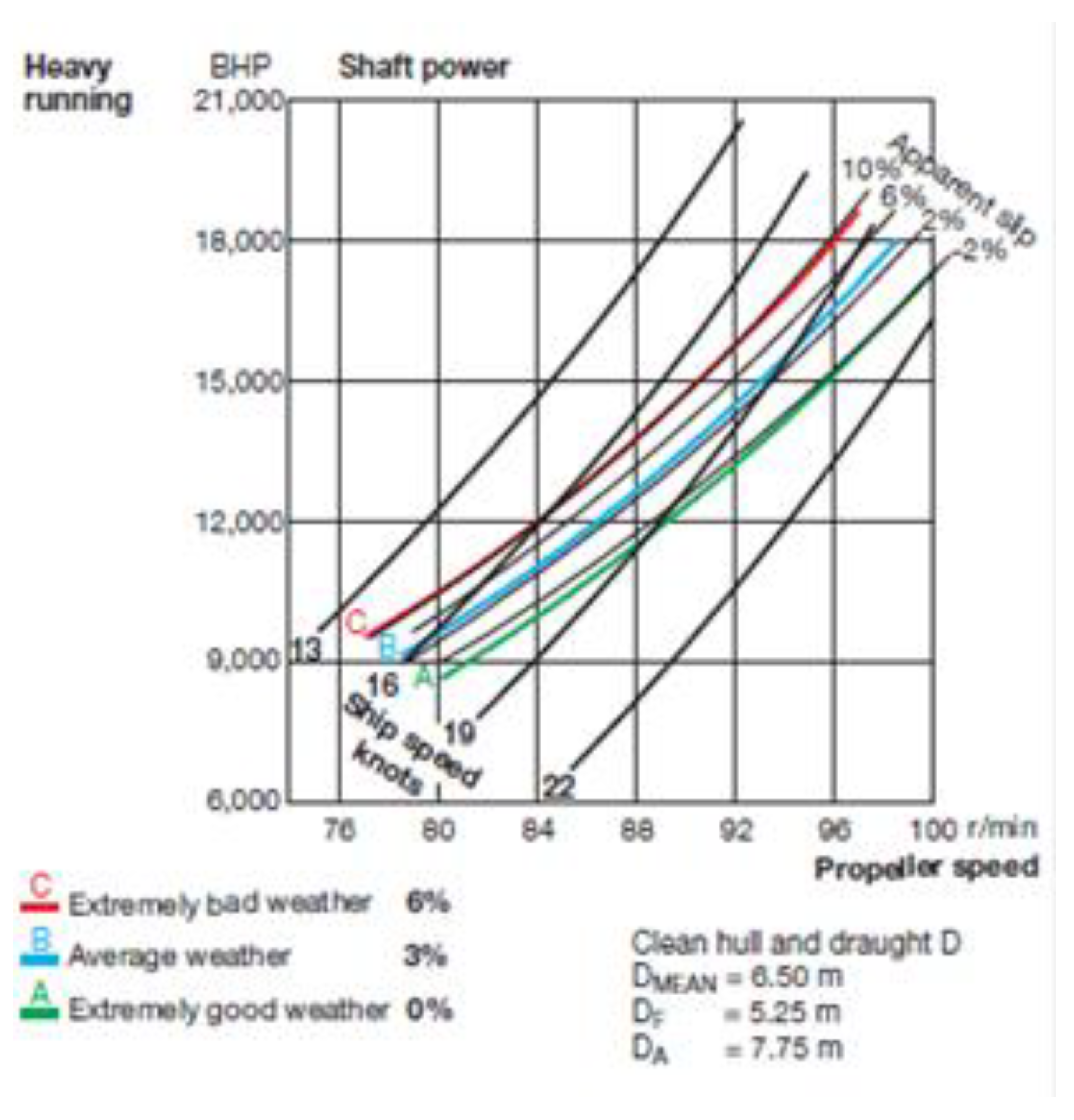
Figure 2.
(“quasi”-) steady state power delivered by the propeller shaft to the fixed pitch screw propeller (FPP), as a function of the (“quasi”-) steady rotational speed of the FPP propeller, or of the (“quasi”-) steady TTW speed, a) at sea trials “ideal” condition upon the latest delivery of a vessel by a shipyard after a new building or a major modification, and b) at the same vessel’s “virtual sea trials” (“ideal”), voyage specific, 80% (percentage value to be inversed against unity for sustaining the same, “new building or major modification”, ideal conditions shaft rotational speed) “service” condition (“service margin”), and at the same hydrostatic conditions.
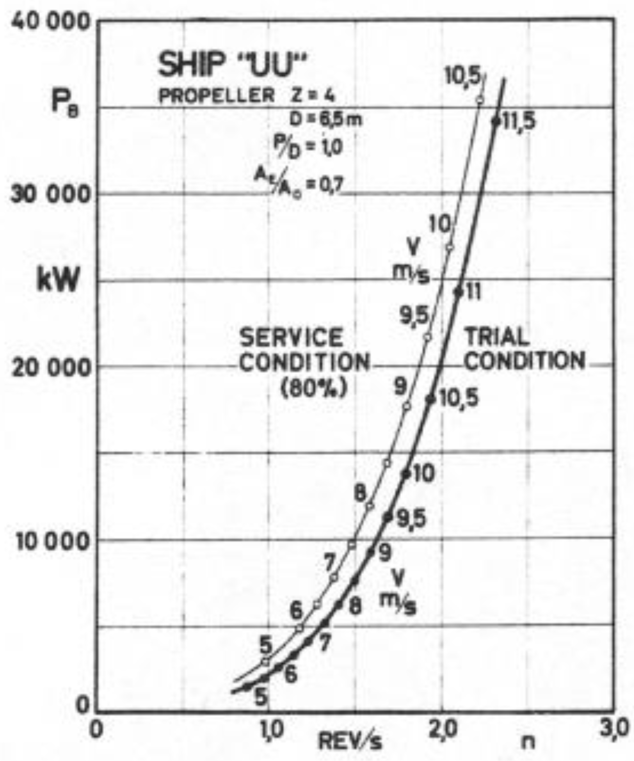

Table 1.
10 vessels’ fleet main engines specifics.
| Vessel Number | Power (MCR, KW) | RPM (MCR) | Number of Cylinders | Cylinder Bore (m) | Stroke (m) |
|---|---|---|---|---|---|
| 1 | 13560 | 105 | 6 | 0.6 | 2.4 |
| 2 | 13560 | 105 | 6 | 0.6 | 2.4 |
| 3 | 13560 | 105 | 6 | 0.6 | 2.4 |
| 4 | 11080 | 83 | 6 | 0.62 | 2.658 |
| 5 | 11080 | 83 | 6 | 0.62 | 2.658 |
| 6 | 11080 | 83 | 6 | 0.62 | 2.658 |
| 7 | 11080 | 83 | 6 | 0.62 | 2.658 |
| 8 | 15088 | 71.8 | 6 | 0.72 | 3.086 |
| 9 | 15088 | 71.8 | 6 | 0.72 | 3.086 |
| 10 | 15200 | 90 | 7 | 0.65 | 2.73 |
Table 2.
Number of legs (voyages) and of reporting intervals per vessel.
| Vessel Number | Number of Legs | Analysis Type 1 | Analysis Type 2 | Analysis Type 3 | Reporting Intervals |
|---|---|---|---|---|---|
| 1 | 38 | 38 | 38 | 38 | 306 |
| 2 | 31 | 31 | 31 | 31 | 333 |
| 3 | 35 | 35 | 35 | 35 | 297 |
| 4 | 29 | 29 | 29 | 29 | 284 |
| 5 | 5 | 5 | 5 | 5 | 87 |
| 6 | 4 | 4 | 4 | 4 | 81 |
| 7 | 32 | 32 | 32 | 32 | 298 |
| 8 | 13 | 13 | 13 | 13 | 172 |
| 9 | 30 | 30 | 30 | 27 | 165 |
| 10 | 5 | 5 | 5 | 5 | 49 |
Table 3.
Analysis Type 1: Some key / critical results.
| Vessel Number | Column 1 (%) | Column 2 (%) | Column 3 (%) | Column 4 (%) | Column 5 (%) | Column 6 (%) | Column 7 (%) | |
|---|---|---|---|---|---|---|---|---|
| 1 | 1.38 | 0.00 | 4.33 | 5.79 | 50.1 | 92.1 | 46.2 | |
| 2 | 0.89 | 0.00 | 9.40 | 6.99 | 50.1 | 91.8 | 46.0 | |
| 3 | 0.01 | 0.00 | 4.76 | 4.92 | 47.6 | 89.5 | 42.6 | |
| 4 | 0.06 | 0.00 | 1.71 | 3.74 | 52.8 | 91.6 | 48.4 | |
| 5 | 0.05 | 3.74 | 2.62 | 3.82 | 50.9 | 92.1 | 46.9 | |
| 6 | 0.10 | 0.00 | 5.21 | 6.65 | 48.3 | 92.4 | 44.6 | |
| 7 | 0.02 | 0.00 | 0.88 | 2.62 | 53.2 | 91.6 | 48.7 | |
| 8 | 4.17 | 0.00 | 0.98 | 4.38 | 56.2 | 91.7 | 51.5 | |
| 9 | 0.06 | 4.30 | 5.70 | 5.68 | 55.8 | 90.2 | 50.4 | |
| 10 | 4.89 | 0.00 | 0.06 | 5.20 | 57.8 | 91.5 | 52.8 |
Table 4.
Analysis Types 2 and 3: Some key / critical results.
| Vessel Number | Column 1 (%) | Column 2 (%) | Column 3 (%) | Column 4 (%) | Column 5 (%) | Column 6 (%) | Column 7 (%) | |
|---|---|---|---|---|---|---|---|---|
| 1 | 2.72 | 10.63 | 20.29 | 15.11 | 0.73 | 0.00 | 7.27 | |
| 2 | 4.13 | 9.43 | 20.47 | 12.67 | 0.86 | 0.00 | 10.58 | |
| 3 | 2.02 | 4.64 | 12.38 | 8.73 | 0.52 | 0.00 | 4.29 | |
| 4 | 1.39 | 0.00 | 12.36 | 13.64 | 1.04 | 0.00 | 9.79 | |
| 5 | 0.85 | 3.73 | 7.05 | 8.92 | 0.16 | 0.00 | 1.87 | |
| 6 | 0.36 | 0.00 | 10.10 | 8.11 | 0.63 | 0.00 | 11.21 | |
| 7 | 2.02 | 1.76 | 11.50 | 16.19 | 0.81 | 0.00 | 8.19 | |
| 8 | 1.13 | 5.85 | 9.12 | 12.27 | 1.76 | 2.22 | 6.33 | |
| 9 | 2.96 | 7.24 | 13.70 | 10.79 | 1.97 | 1.96 | 11.65 | |
| 10 | 1.18 | 0.00 | 7.95 | 6.20 | 1.42 | 0.00 | 10.50 |
Disclaimer/Publisher’s Note: The statements, opinions and data contained in all publications are solely those of the individual author(s) and contributor(s) and not of MDPI and/or the editor(s). MDPI and/or the editor(s) disclaim responsibility for any injury to people or property resulting from any ideas, methods, instructions or products referred to in the content. |
© 2024 by the authors. Licensee MDPI, Basel, Switzerland. This article is an open access article distributed under the terms and conditions of the Creative Commons Attribution (CC BY) license (http://creativecommons.org/licenses/by/4.0/).
Copyright: This open access article is published under a Creative Commons CC BY 4.0 license, which permit the free download, distribution, and reuse, provided that the author and preprint are cited in any reuse.


