Submitted:
25 September 2024
Posted:
25 September 2024
You are already at the latest version
Abstract
Keywords:
1. Introduction
1.1. Research Background
2. Experimental Section
2.1. Idler-Flexible Ring Pairs
2.2. Test Equipment and Methods
2.3. Surface Characterization
3. Results and Analysis
3.1. Influence of Idler Materials on the Electrical Contact Properties of Rolling Rings
3.2. Wear and Material Transfer of Idler-Flexible Ring Pairs
4. Conclusions
Acknowledgments
References
- P.E. Jacobson, Rolling electrical transfer coupling improvements, EP, 2003.
- C. Junxing, R. Mingzhe, Y. Fei, W. Yi, S. Hao, Y. Yun, Numerical research on the electrical contact model and thermal analysis of the Roll-Ring, 2013 2nd International Conference on Electric Power Equipment - Switching Technology (ICEPE-ST), 2013, pp. 1-4.
- X. Hou, L. Wang, Q. Li, J. Wang, J. Liu, Review of Key Technologies for High-Voltage and High-Power Transmission in Space Solar Power Station, Transactions of China Electrotechnical Society 33(14) (2018) 3385-3395.
- Y. Sun, C. Song, Z. Liu, J. Li, Y. Sun, B. Shangguan, Y. Zhang, Effect of relative humidity on the tribological/conductive properties of Cu/Cu rolling contact pairs, Wear 436-437 (2019) 203023. [CrossRef]
- T. Chen, C. Song, Y. Zhang, K. Niu, Z. Liu, L. Wang, C. Sun, M. Li, Y. Zhang, Current-carrying contact character and wear behavior of an elastic ring at different rolling speeds, Engineering Failure Analysis 131 (2022) 105825. [CrossRef]
- Cai Y, Meng Y, Cheng Y , et al. Alkylboronic acid esterified cellulose nanocrystal by an improved green method as an efficient lubricant nanoadditive for friction and wear reduction[J].Chemical Engineering Journal,2024,496153912-153912.
- Yan Z, Liu J ,Shi X , et al. Tribological properties and transfer behaviors of WS2-Ag nanocomposite films with structure evolution for aerospace application[J].Applied Surface Science,2024,674160928-160928.
- Raut A, Nunez E E ,Sellers R , et al. The effect of reinforcing fillers on the tribological performance of PTFE composites for a sustainable environment[J].Wear,2024,556-557205524-205524.
- Kian B, Vasilis T, Ahmad A , et al. Polymer transfer film formation from cryogenic to elevated temperatures[J].Friction,2024,12(9):2018-2032.
- Yan C, Zhang Y, Zeng Q, et al. Comparative investigation on the tribocorrosion resistance of Ti6Al4V and 60NiTi alloys inimulated seawater environment[J].Wear,2024,550-551205423-.
- Lv X, Pei X, Yang S , et al. Tribological behavior of PEEK based composites with alternating layered structure fabricated via fused deposition modeling[J].Tribology International,2024,199109953-109953.
- Longxiao Z, Ting X, Kun C, et al. Quantitative characterization of the transfer film morphology of SiO2/PTFE composite[J].Wear,2021,484-485.
- Zhang K, Lin Z, Chen J, et al. An ingenious synergistic solid lubricant of copper and graphite for exceptional wear resistance of the SCF/PTFE/PEEK composite[J].Tribology International,2024,195109583.
- Ren B, Gao L ,BotaoXie, et al. Tribological properties and anti-wear mechanism of ZnO@graphene core-shell nanoparticles as lubricant additives[J].Tribology International,2020,144106114-106114.
- Oyamada, T., Ono, M., Miura, H., & Kuwano, T. (2013). Effect of Gas Environment on Friction Behavior and Tribofilm Formation of PEEK/Carbon Fiber Composite. Tribology Transactions, 56(4), 607–614. [CrossRef]
- McCook N, Hamilton M, Burris D , et al. Tribological results of PEEK nanocomposites in dry sliding against 440C in various gas environments[J].Wear,2007,262(1-2):1511-1515.
- Theiler G, Gradt T. Environmental effects on the sliding behaviour of PEEK composites[J].Wear,2016,368-369278-286.
- Nikonovich M, Ramalho A, Emami N .Effect of cryogenic aging and test-environment on the tribological and mechanical properties of PEEK composites[J].Tribology International,2024,194109554-.
- Theiler G, Gradt T. Friction and wear of PEEK composites in vacuum environment[J].Wear,2010,269(3):278-284.
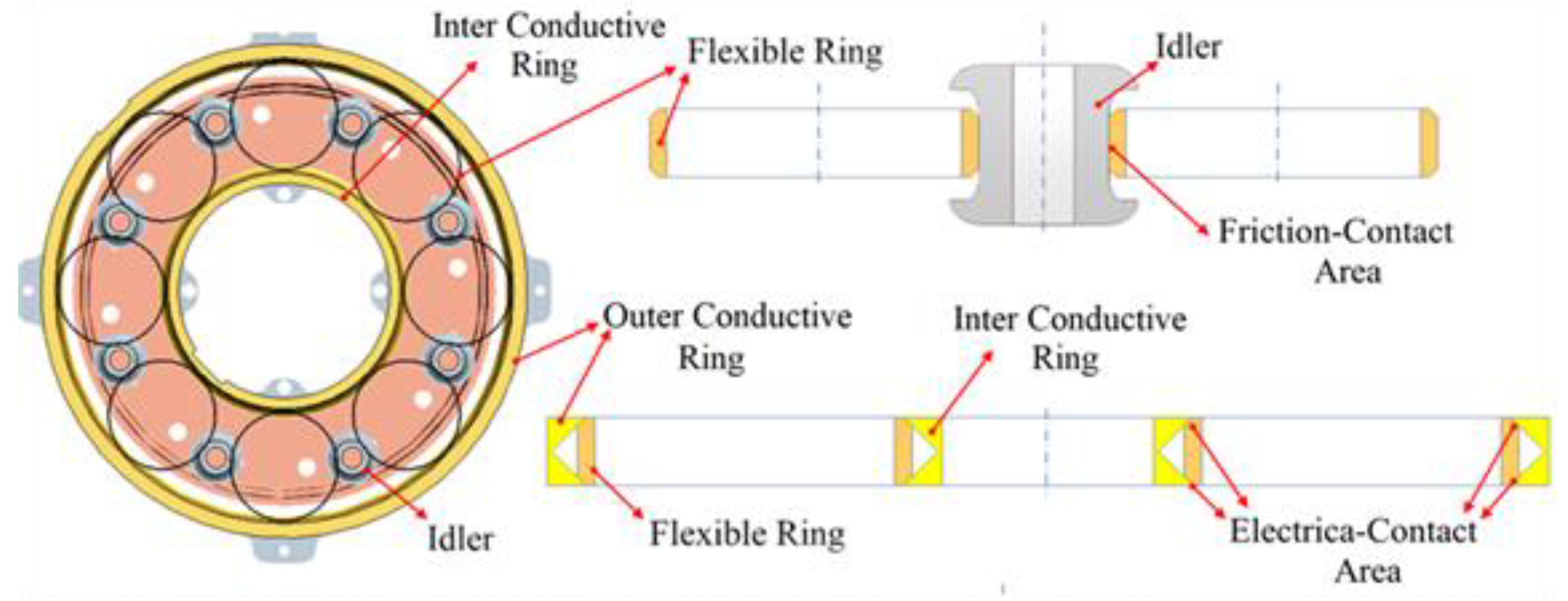
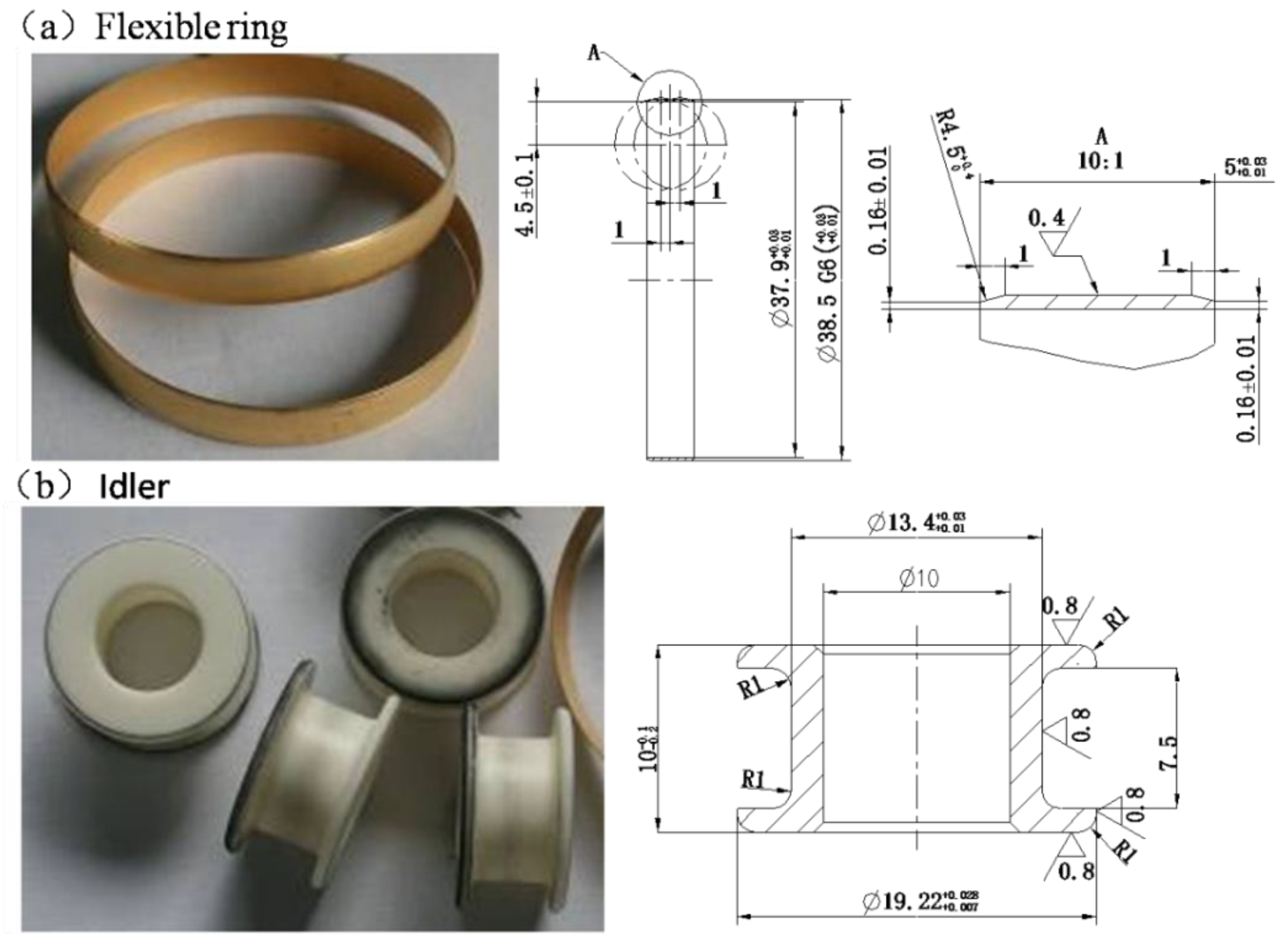
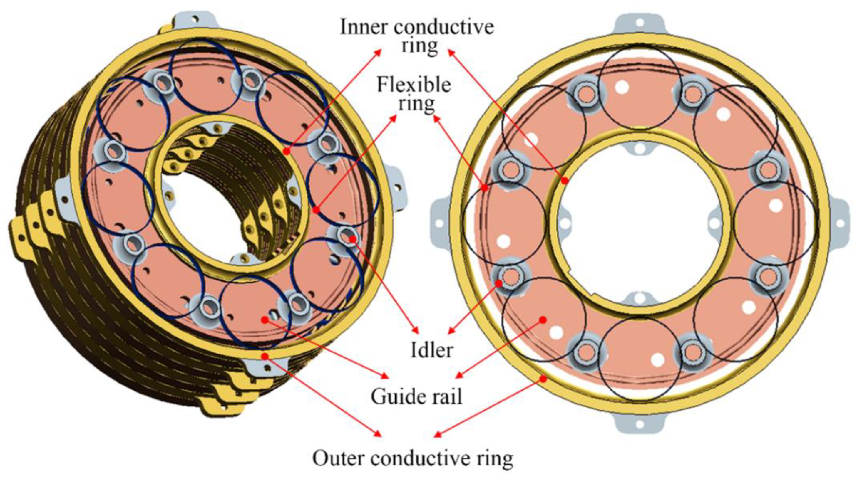
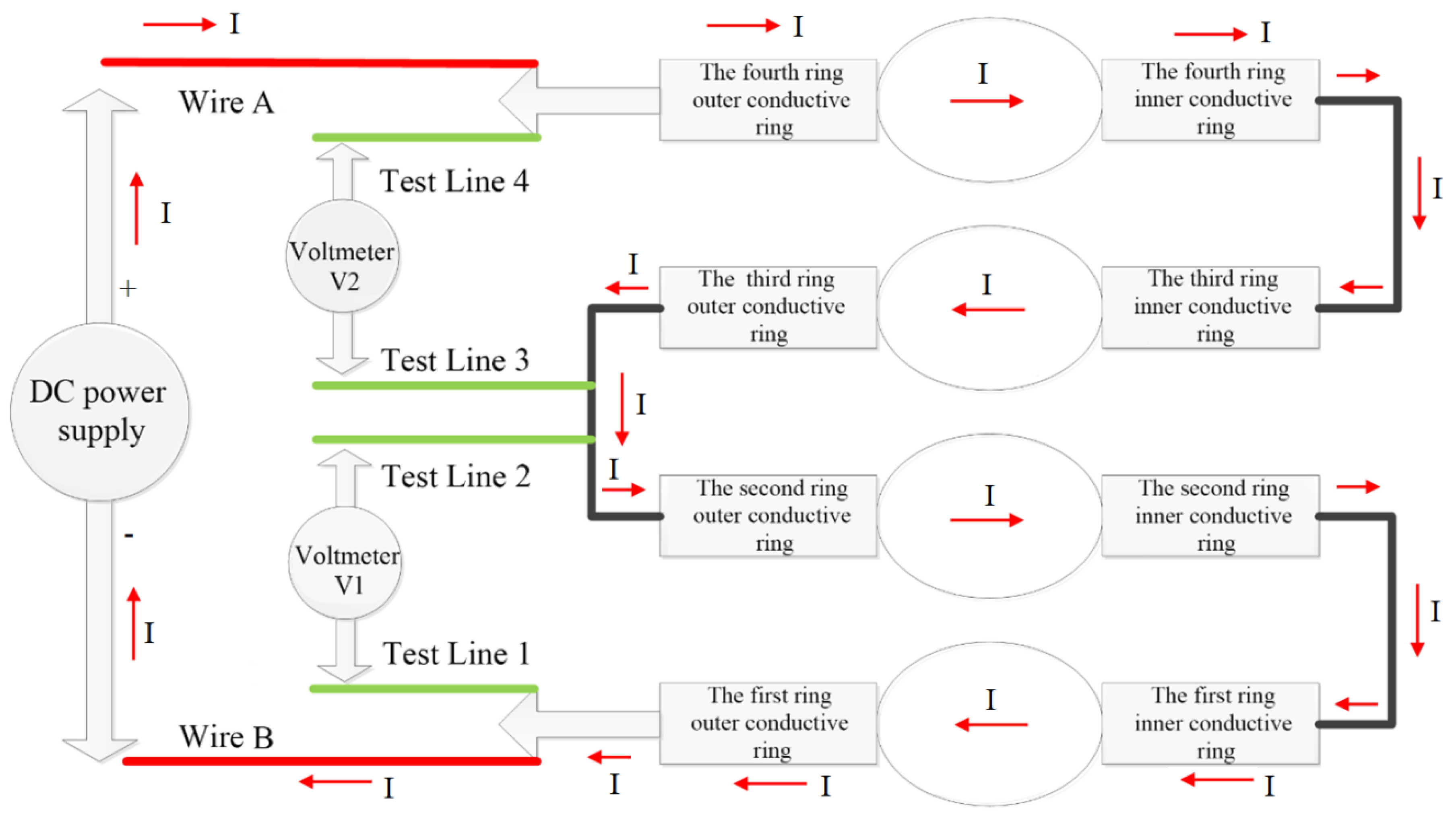
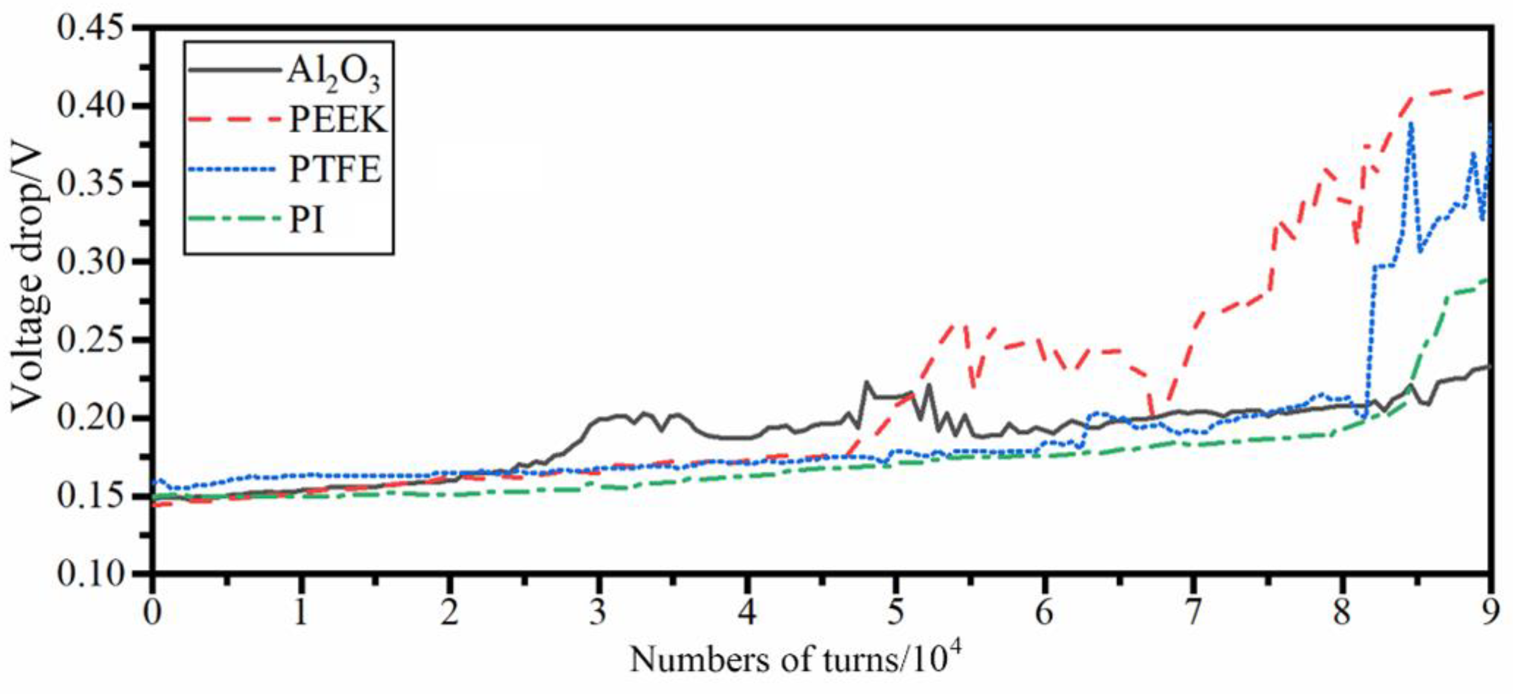
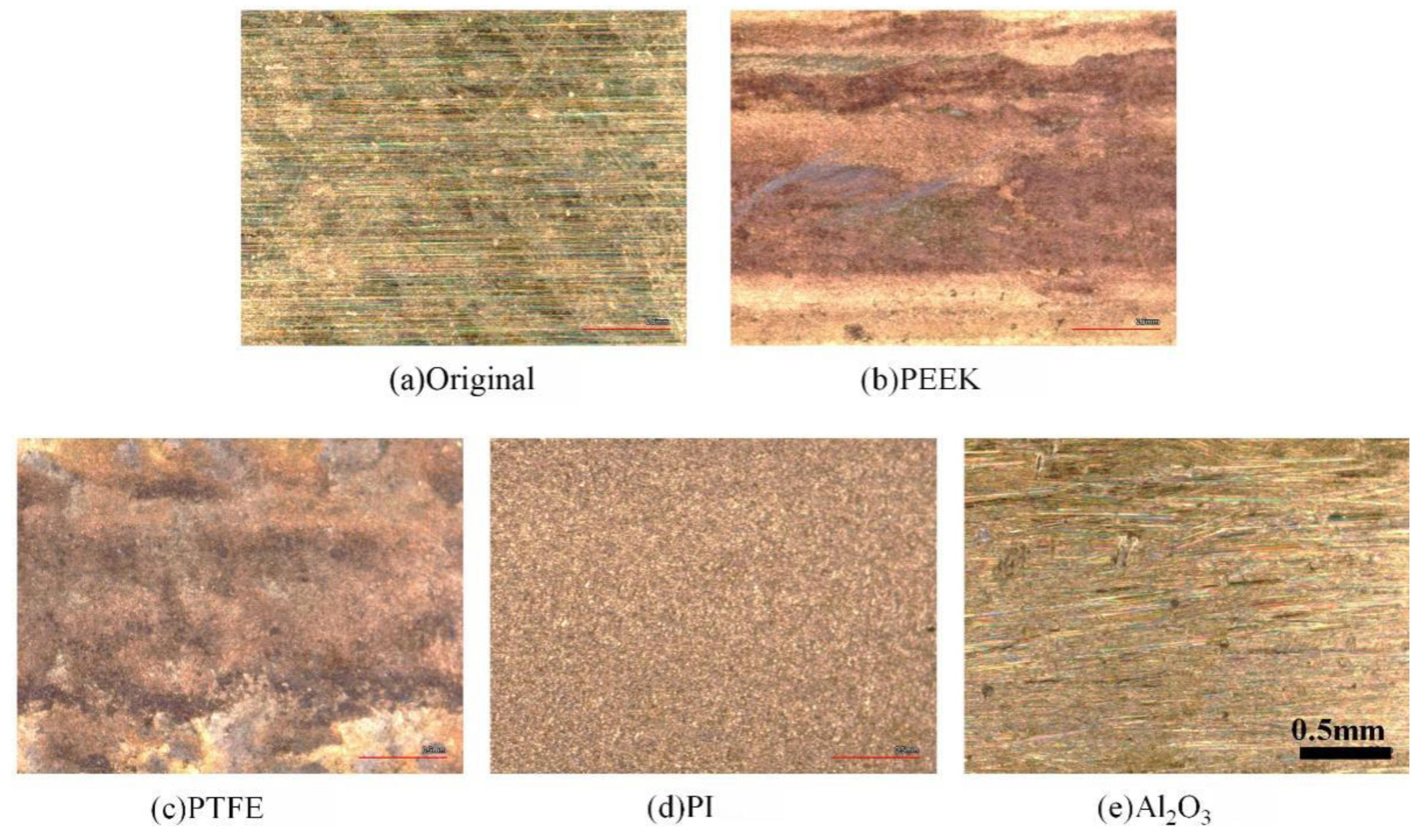

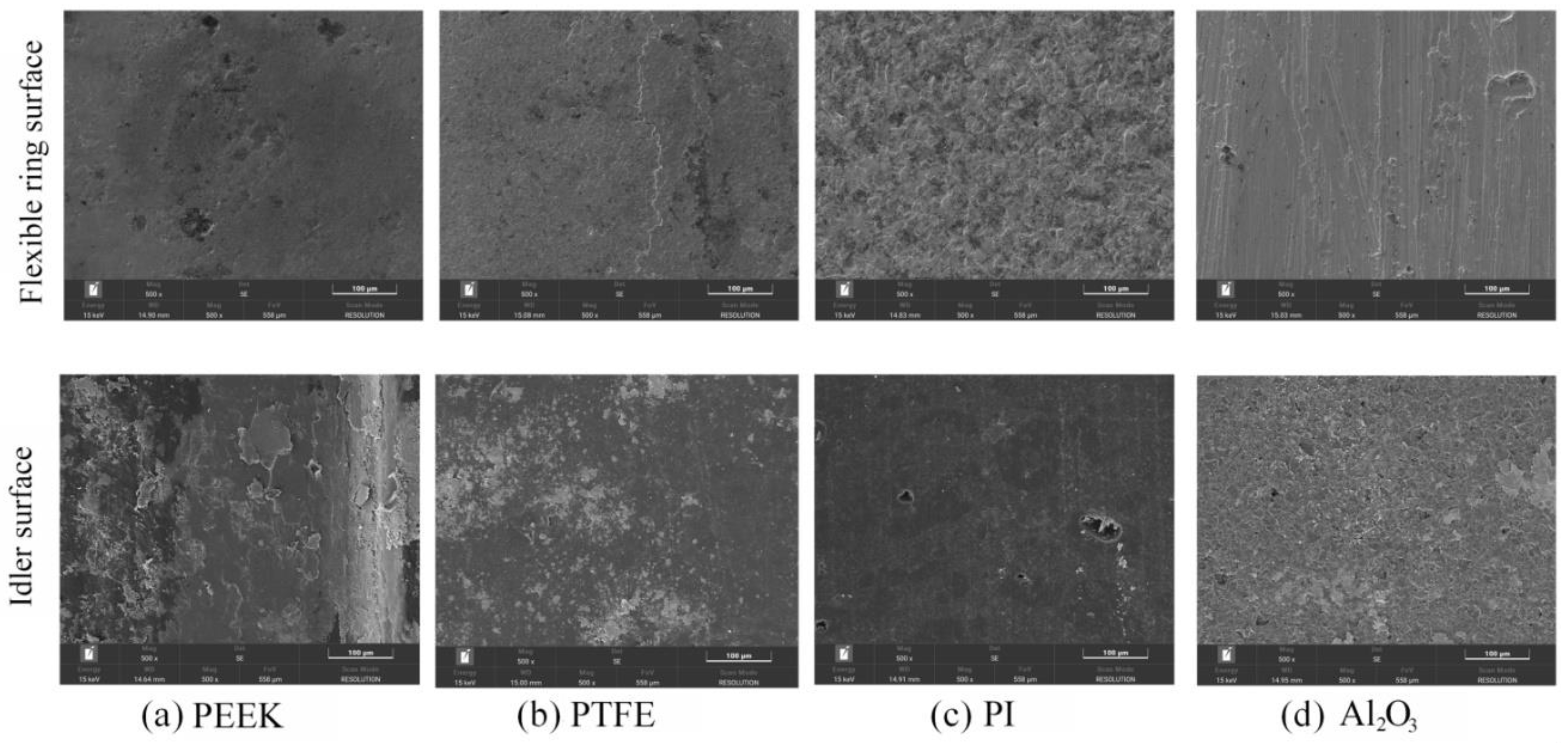
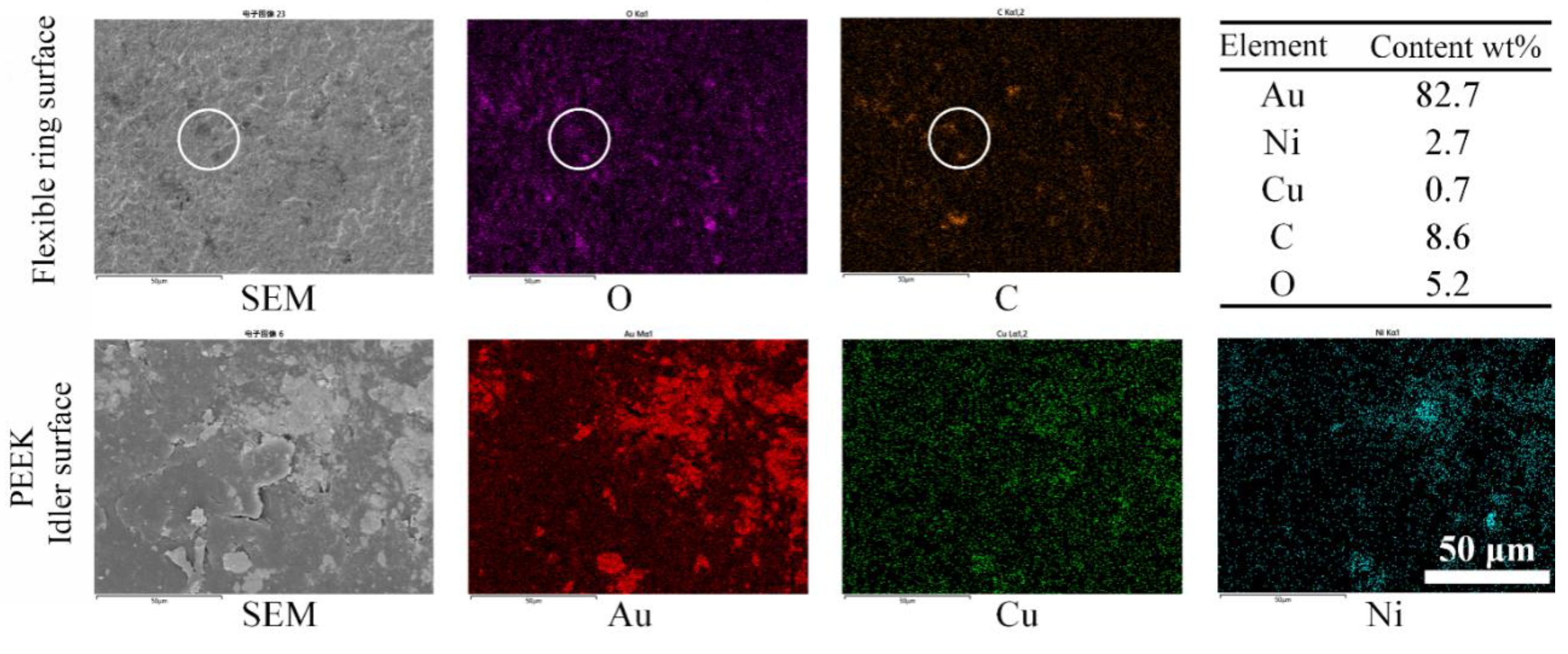
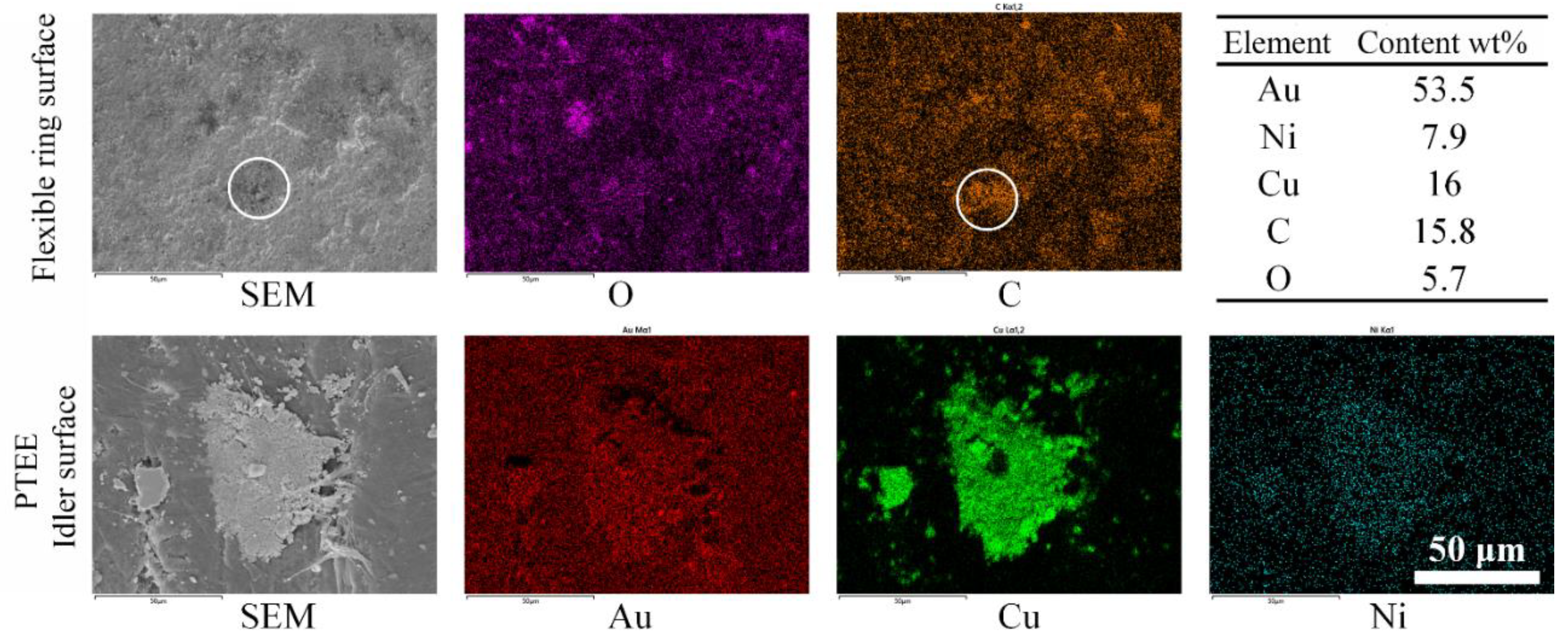
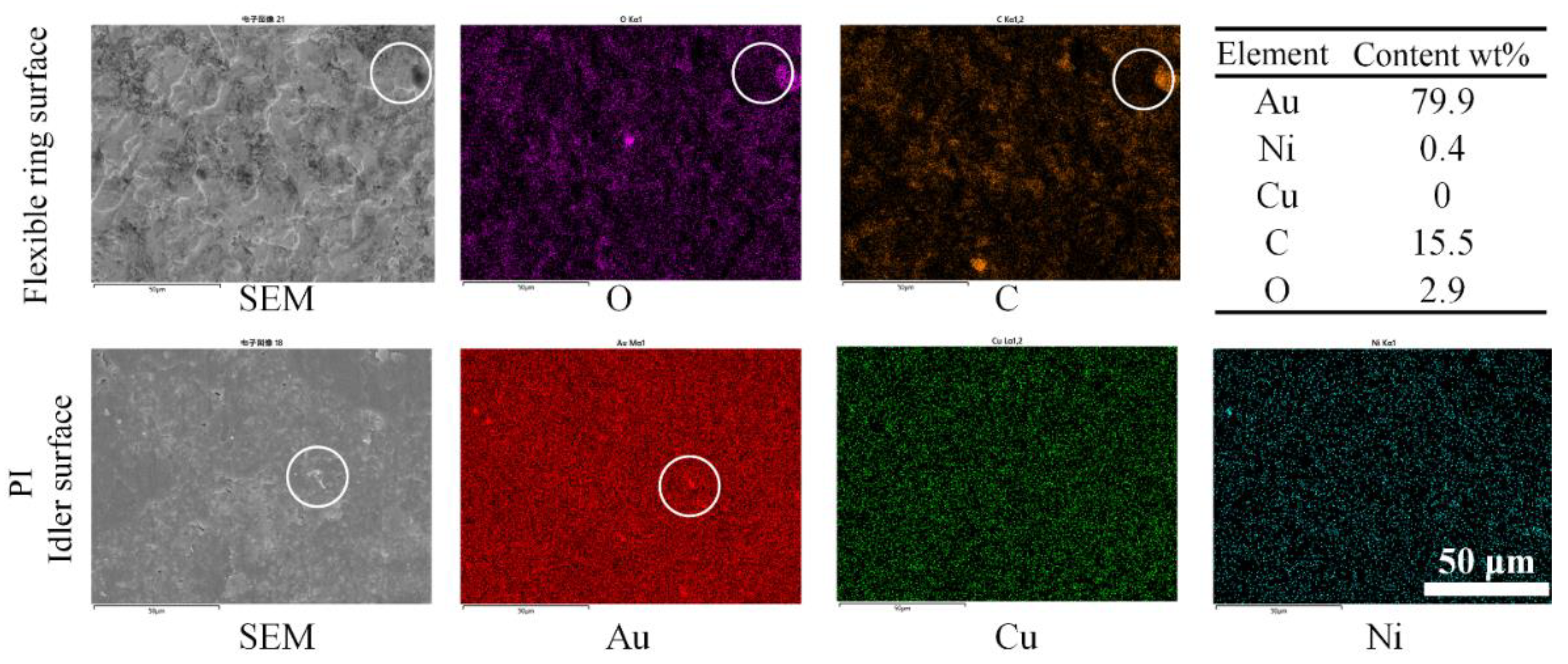
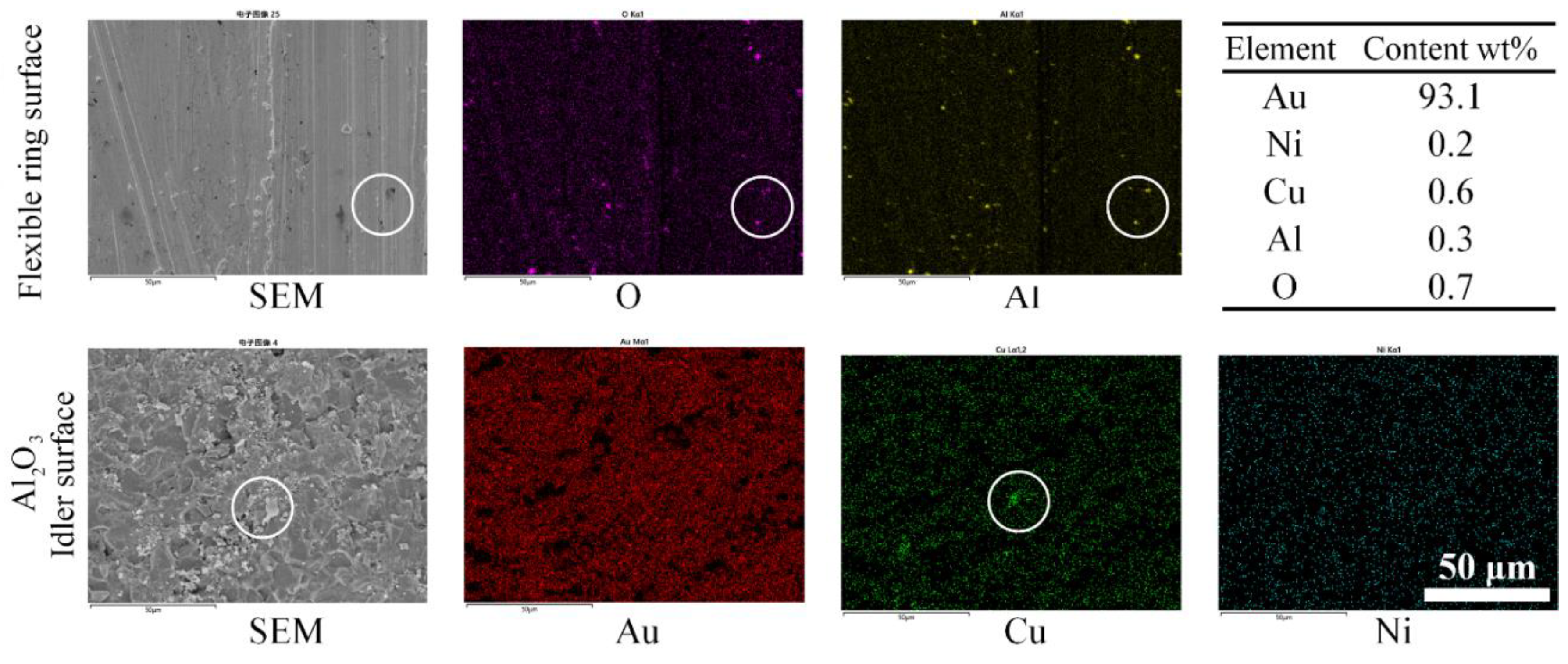


| Idler material | Parameters | ||
|---|---|---|---|
| Roughness (μm) | Hardness (Hv) | Molecular formula | |
| PTFE | about0.8 | 5 | (C2F4)n |
| PI | about0.8 | 108 | (C35H28N2O7)n |
| PEEK | about0.8 | 211 | (C19H12O3)n |
| Al2O3 | about0.8 | 920 | Al2O3 |
Disclaimer/Publisher’s Note: The statements, opinions and data contained in all publications are solely those of the individual author(s) and contributor(s) and not of MDPI and/or the editor(s). MDPI and/or the editor(s) disclaim responsibility for any injury to people or property resulting from any ideas, methods, instructions or products referred to in the content. |
© 2024 by the authors. Licensee MDPI, Basel, Switzerland. This article is an open access article distributed under the terms and conditions of the Creative Commons Attribution (CC BY) license (http://creativecommons.org/licenses/by/4.0/).


