1. Introduction
Renewable energy has grown significantly throughout the decades [
1,
2]. One of the equipment that leads this renewable trend is the wind turbine [
3,
4]. The wind’s kinetic energy is harvested from the wind by turning the rotor using blades, which end up in a gearbox – working as a multiplier – raising the speed and reducing the torque proportionally. This movement reaches a generator that produces electrical energy [
5,
6]. Many fracture analyses in the literature focus on bearing failure; for example, Sankar et al. [
7], Bruce [
8], and Evans [
9] studied the gearbox bearings, concluding the bearings failed due to overloading and fatigue. Dilip et al. [
10] worked on improving the lubrication system of gearboxes from 2 to 4 MW and towards oil purification. The same author reveals the main bearings affected by the lubrication are the high-speed bearing at the high-speed shaft (HSS) and the helical gear bearing at the intermediate shaft (IMS). Rajinikanth et al. [
11] leaned to another venue and studied the failure mode of planet gears, concluding the failure initiated with micro pitting, aggravating the subsurface microcracks and leading to spalling, which, afterward, generated the complete fracture. The same research approach is followed by Wang et al. [
12] who suggested that the gearbox of his study fractured due to crack-initiation sites of a fatigue fracture situated at the bottom of pits left by particles broken from the tooth flank. In addition, the same author linked the fracture with the finite element analysis and summed up the presence of an uneven load applied to the gears contributed to the failure. Bai, et al. [
13] studied the fracture of gears of a wind turbine and proposed improvements, including raising the gear pressure angle, inducing compressive residual stress, having a high surface hardness with a low core hardness, and a large effective case depth to inhibit crack nucleation and avoid fatigue phenomena. With that said, this paper aims to provide an overview and an analysis of the components of a 1.6 MW gearbox, beginning with a numerical simulation (Finite Element Analysis – FEA) to determine the regions of high stresses, followed by verifying the hydraulic system, bearings, sun shaft, planet carrier, planet gears, and gear tooth. In the end, the root cause of the failure is determined based on the FEA and the analysis of all the gearbox components.
2. Materials and Methods
2.1. Gearbox Anatomy
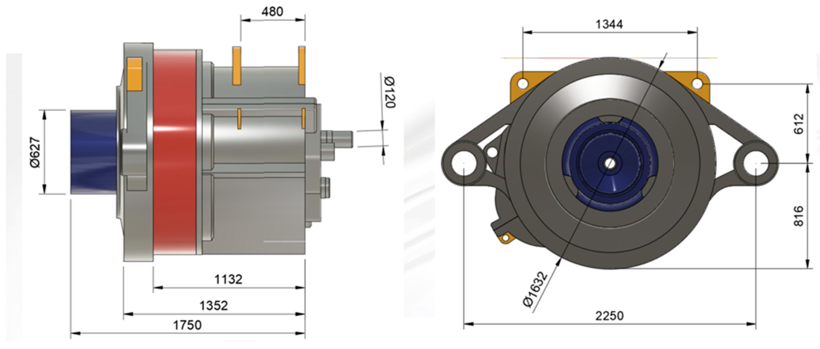
The gearbox analyzed is shown in
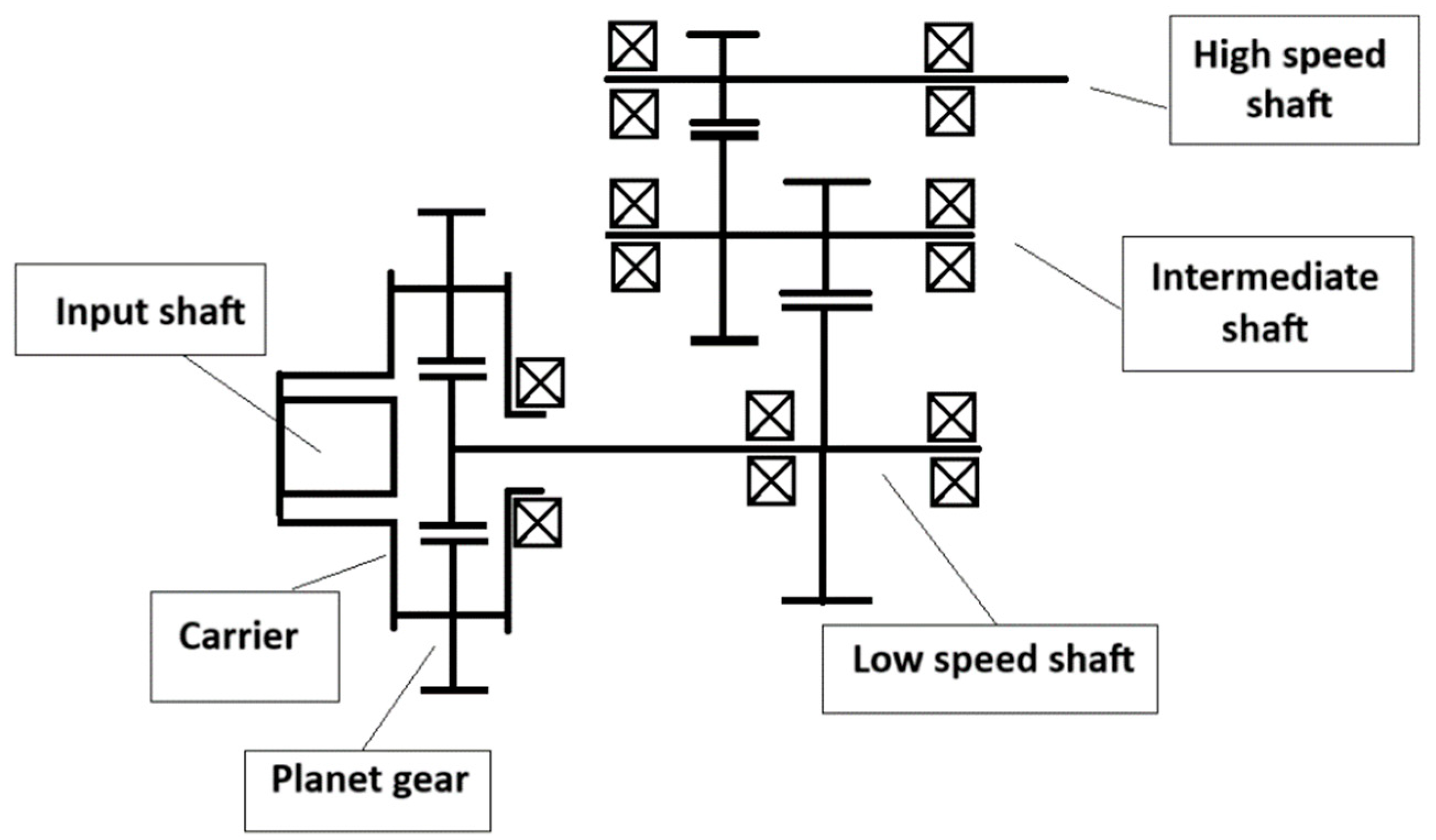
Figure 1, which presents the torque/speed streamline and the main dimensions of a 1.6 MW gearbox. It also demonstrates the planet stage, which receives the movement from the rotor by the main shaft and has the lowest speed; then, the movement is transferred to the intermediate stage and ends in the high-speed stage (output) to the generator. The analysis of the gearbox‘s failure started with a peripherical verification with an initial inspection by borescope to check the lubrication system and filtering, pressure into the cooler, functionality of heaters, and sensors. Afterward, a more detailed evaluation was performed by checking the conditions of gears, shafts, and bearings.
2.2. Power and Analysis of the Torque at the Planet Stage
The methods utilized for the analysis of the peripherical components were as follows. Heaters and sensors were checked by measuring their continuity and resistance, and the manifold and the pump–coupling components were disassembled and checked. The shafts were visually inspected for marks, dents, pitting, corrosion, and other significant damages, while the gears and sun gear were visually checked, seeking marks, dents, and craters. The gears were also visually analyzed using a Borescope View Tech model VJ-3 diameter 6 and 3 mm.
Figure 2 was utilized to navigate through the gearbox evaluation. Another critical piece of information is analyzing the gearbox functionality, such as speed and torque at each stage. The Equations (1) and (2) were utilized for this purpose:
where P is power in kW,
ρ is the density of the air (kg/m
3),
A is the area of the rotor (m
2),
is the velocity of the air (m/s), and
is dimensionless and constant 0.45 [
14] for a wind turbine with three blades.
T equals torque (N·m), 9,550 is a constant, and
n is the rotation of the blades in min
−1.
A few equations are necessary to determine the speed and torque of each gearbox state. For the planet stage with the tooth ring fixed, the input from the planet carrier, and the output from the sun shaft, Equation (3) is utilized, while for regular gears engagement, Equation 4 is used [
16].
where
is the ratio of a planet stage gearbox,
is the number of teeth of the tooth ring and
is the number of teeth of the sun shaft,
is the ratio of a regular stage gearbox,
is the number of teeth of the input gear, and
is the number of teeth of the output gearbox.
After analyzing the Equations from (1)–(3), few initial statements are possible, which makes the fracture evaluation more robust. The first is that the input side from the equipment rotor and main shaft drives the planet carrier of the gearbox, which, despite having three planets, carries the maximum load on the planet gears, planet gears bearings, and sun shaft. Therefore, this stage is under the highest torque, vector forces, and lowest speed, usually around 16 min
−1 [
17]. On the output side, the gearbox output to the generator presents the lowest torque. Therefore, the main concern is now directed toward failures at the output gear teeth (high-speed shaft) due to high speed.
2.3. Numerical Simulation (Finite Element Method) and Hertz Contact
A numerical simulation using the finite element method was utilized to obtain a map of stresses on the gear teeth and compare it with the fractured zone morphology. The calculation used a linear elastic for structural simulation, as the software is for. The software used for the calculation was the module for numerical calculation present at Autodesk F360. Before the calculation, the deformed area on the tooth was obtained by utilizing the Hertz equation for the contact between two cylinders, which was determined geometrically by studying the teeth‘ geometries, Equations (5)–(7).
where
ν is the coefficient of Poison,
E is the module of Young,
C is the coefficient for material properties,
P is the force applied per gear tooth,
L is the length of the gear,
d1, and
d2 are the diameter of the circles traced on the gear tooth in contact,
b is half of the contact area.
The material considered for the simulation was AISI 4340 350C QT, which has a yield strength of 1,178 MPa and an ultimate tensile strength of 1,240 MPa. As usual, a case hardening with a tensile strength of 2,100 MPa is applied to the teeth.
2.4. Torque at Planetary Stage
Equations (1) and (2) were utilized to understand better the tangential force at the planetary stage and the pressures on the teeth. For the calculation, the wind turbine is rated to 1,600 kW, the air density is 1 kg/m
3, the diameter of the rotor is 100 m, the velocity of the air is 9.7 m/s (Wind-turbine-models.com, 2011–2024), and Betz efficiency is 0.45 [
14]. The rotation of the rotor is considered 16.2 min
−1.
2.5. Investigation of the Main Components of the Gearbox
To get a broader picture and choose the failure’s root cause, a complete verification of all components was done. It started with the peripherical components and moved to the shafts, gears, and bearings. The diagnosis is vital to trace the failed parts and create a broader view of the failure characteristic. The purpose was to gather data to determine the most likely cause of the gearbox.
3. Results and Remarks
3.1. Torque at Planetary Stage
The total torque calculated using the power from Equations (1) and (2) is 943,209 Nm, which resulted in a tangential force of 1,190,916 N per tooth. Considering the area of contact (2b) according to Hertz Equations (5)–(7), the pressure per pair of teeth resulted in 2,170 MPa.
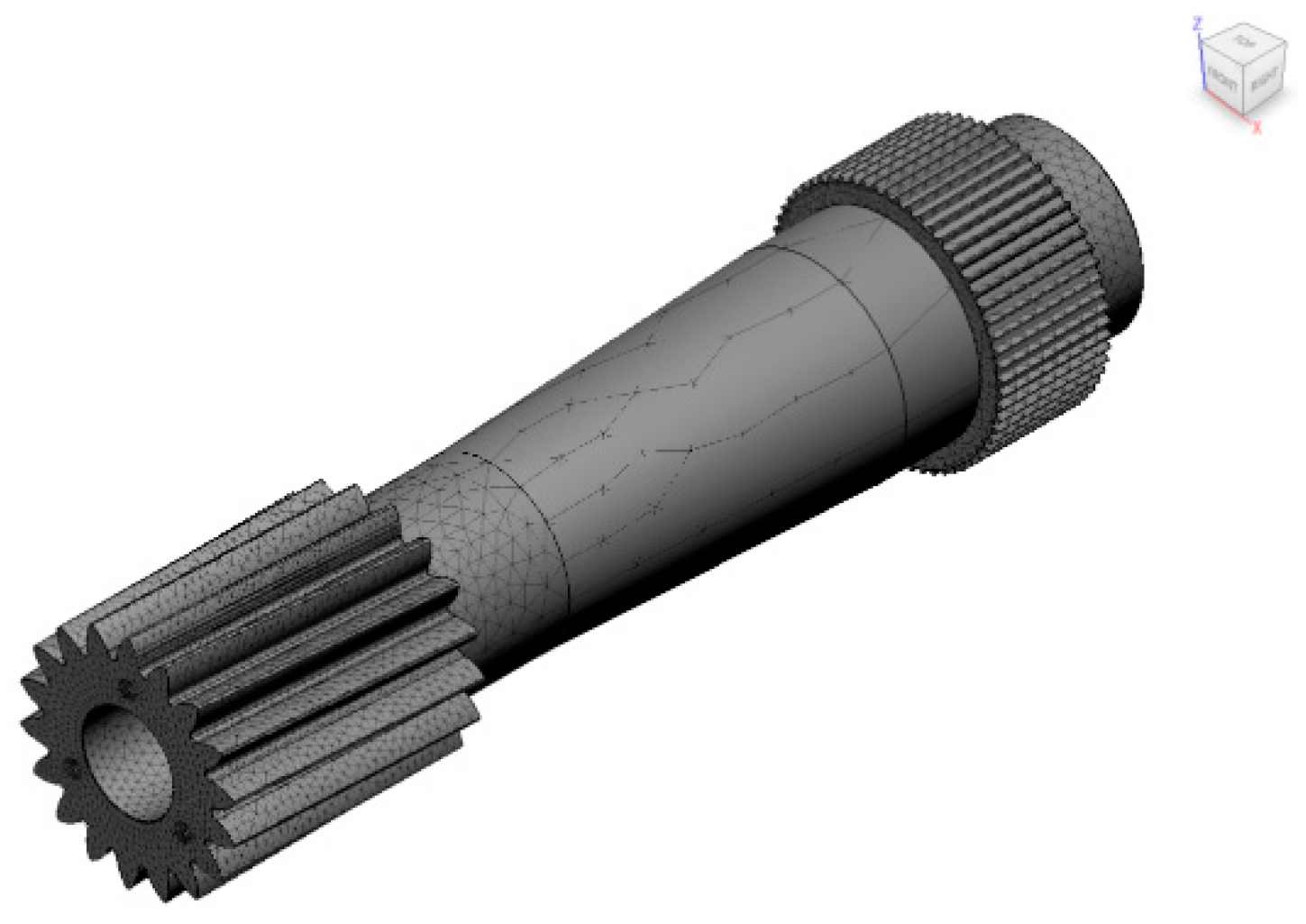
For the mesh’s construction, a parabolic element was used, with an average element size of 10%—the model-based size—the maximum turn angle on curve 60o and a 20% maximum element size—the percentage of average size. The maximum number of refinements is considered 6, with a 5% convergence tolerance and a portion of 40% of the elements to refine. The number of elements is 92,373, and the number of nodes is 141,255.
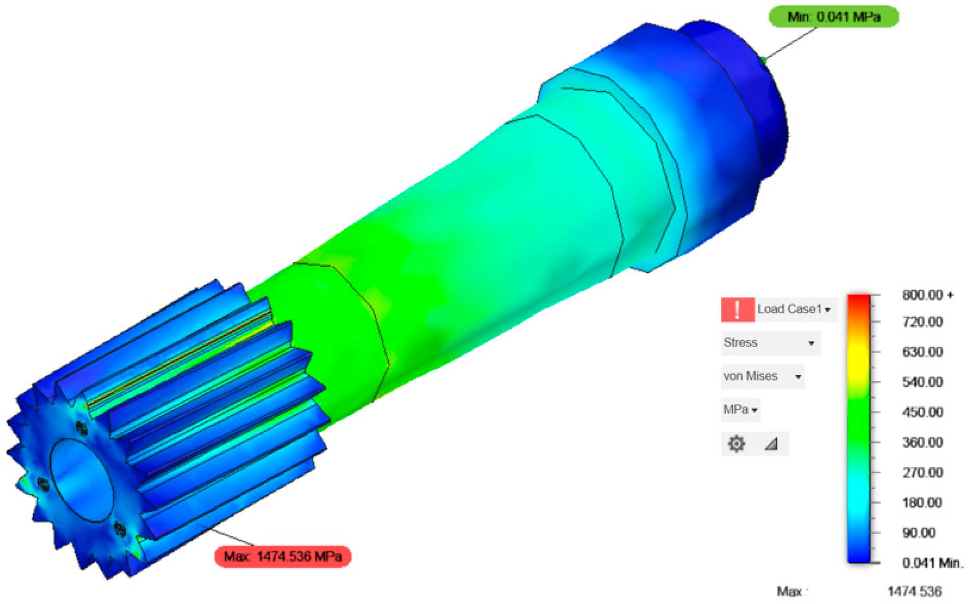
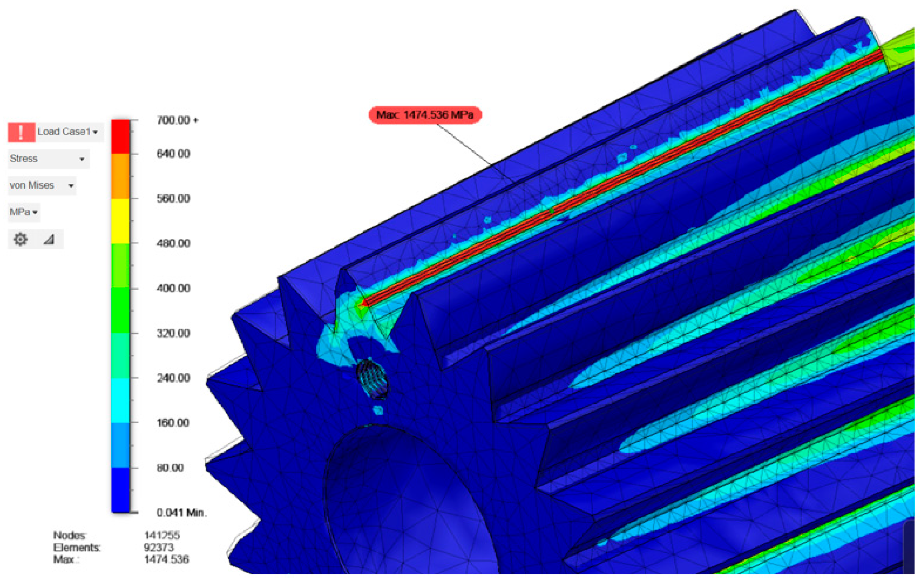
Figure 4 and
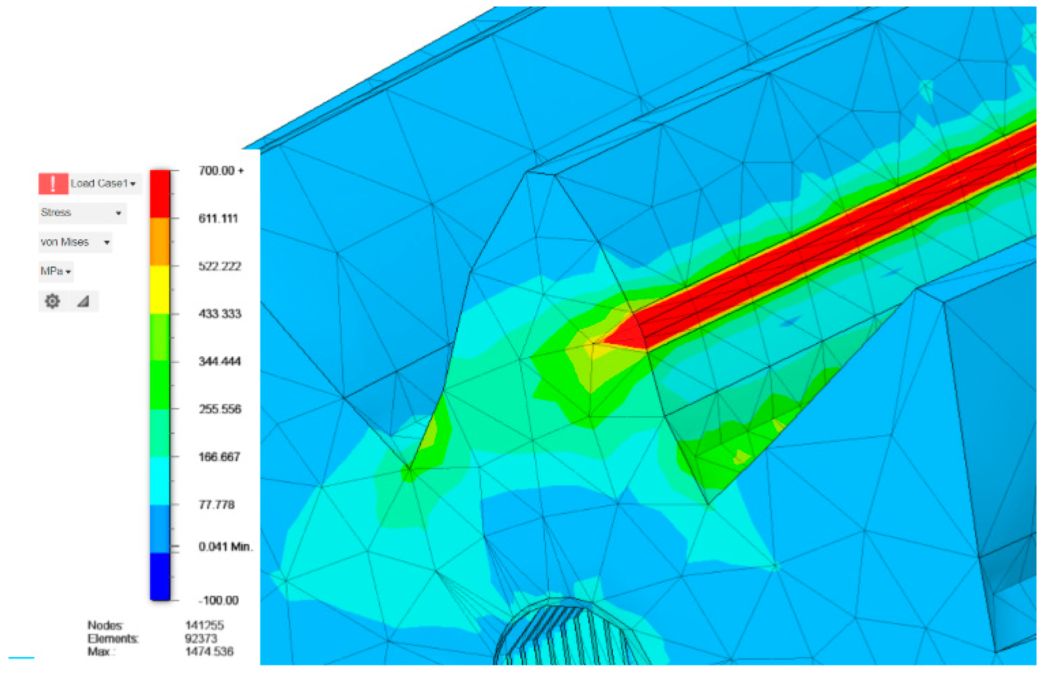
Figure 5 show the von Mises stresses throughout the sun shaft. The highest stress was found in the contact area of the teeth, reaching a maximum of 1,474.536 MPa.
Figure 6 shows the morphology of the von Mises stress. The region of the highest contact and the gradient of stresses are more evident, with the tooth fillet revealed as the second region of high stress. The top land of the tooth does not present high stress.
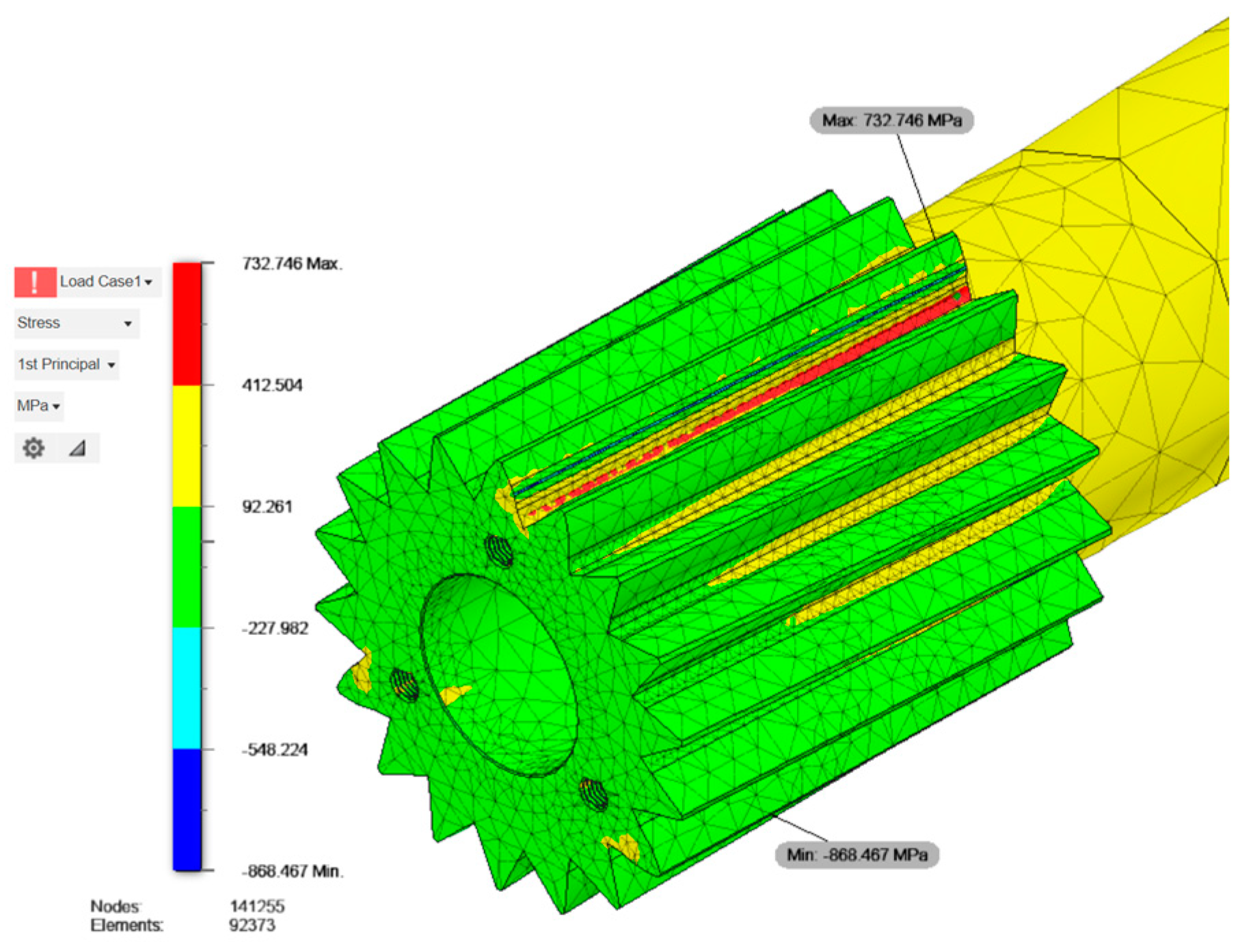
Principal stress σ
1 (
Figure 7) shows the maximum stress at the region of the tooth fillet as the minimum stress. The maximum value is 732.746 MPa, and the minimum is -868.467 MPa.
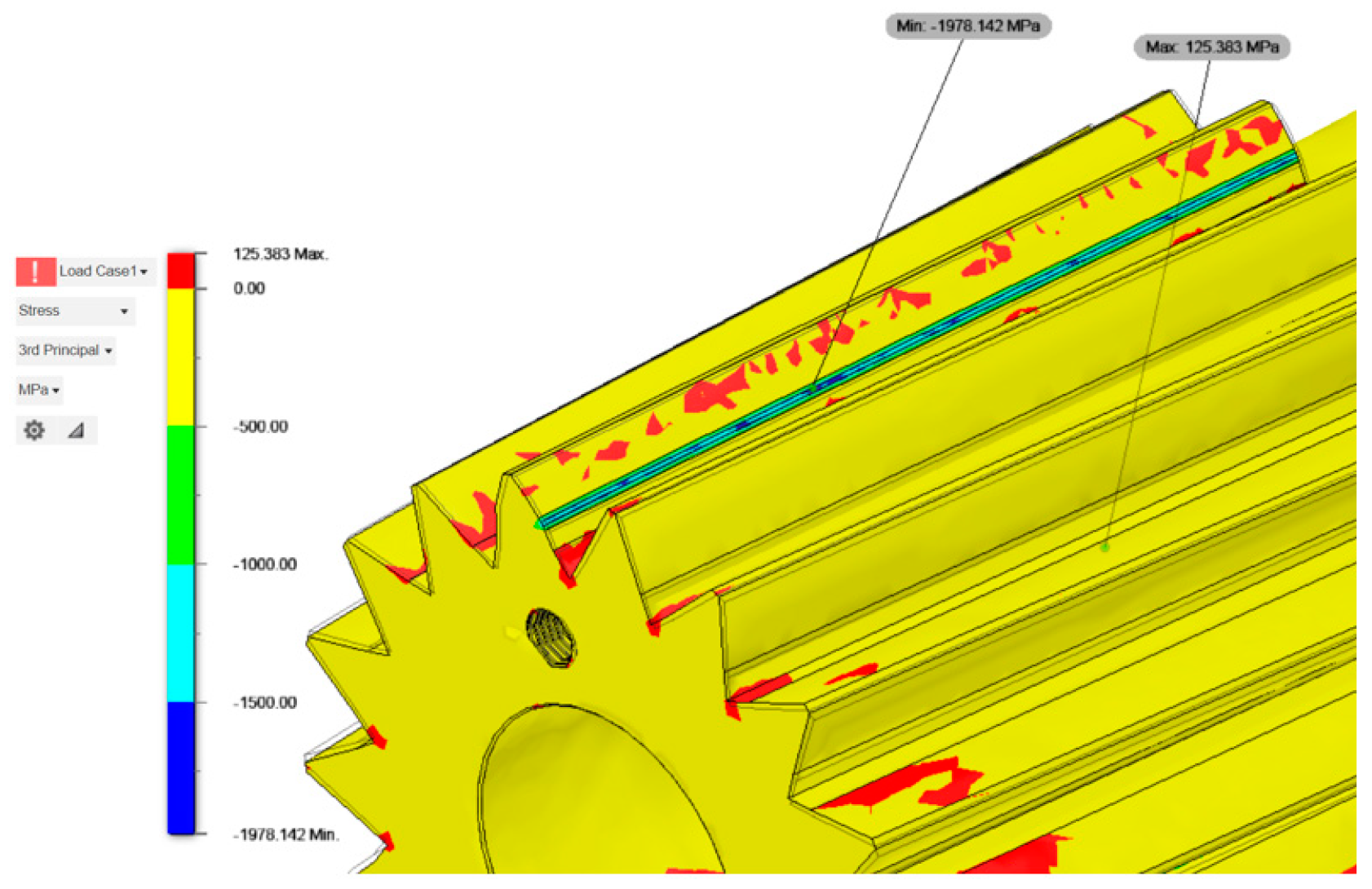
Figure 8 demonstrates stress σ
3 with a maximum compressive stress of -1,978.142 MPa and a tensile stress of 125.383 MPa.
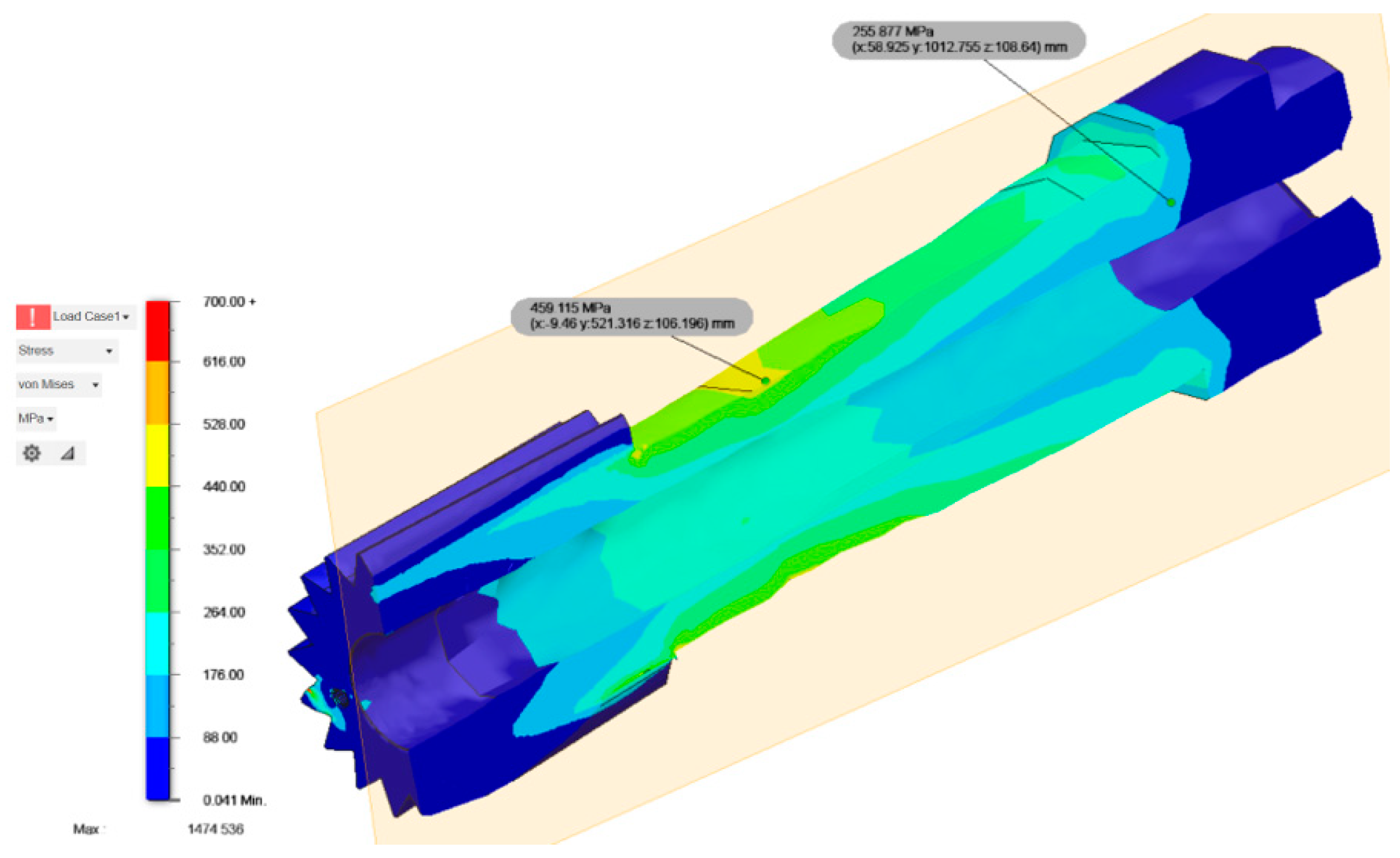
Figure 9 shows a longitudinal cross-section of the sun shaft. There is a von Mises stress of 755.877 MPa close to the spline, where the shaft has a fixed constraint. And a stress of 459.115 MPa close to the gear at the external diameter of the shaft.
3.2. Peripherical Components
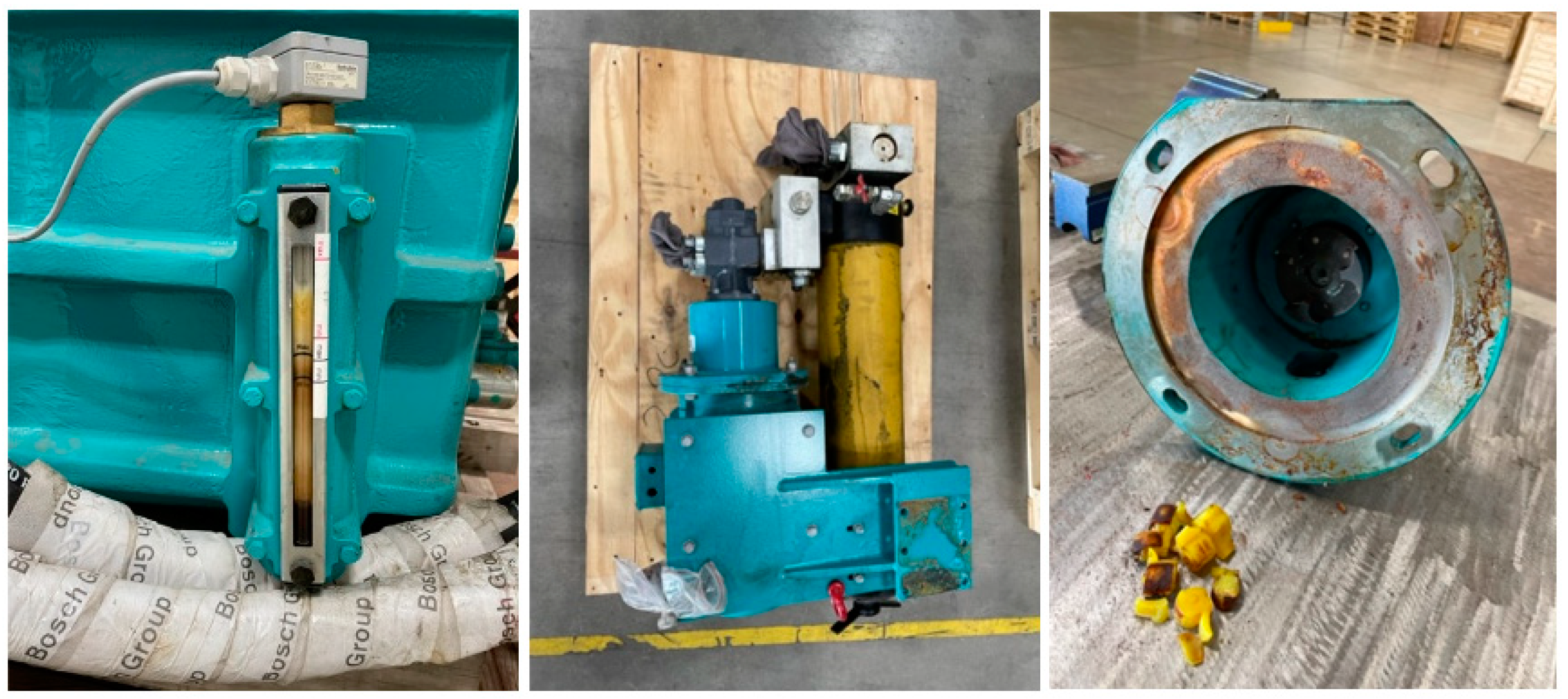
The analyses with pictures that follow demonstrate the significant changes in the original condition or design of the gearbox and its peripherals. The first hint obtained from the condition of the lubrication system was the glass window, which showed a significant presence of air in the oil, creating a thick foam (
Figure 10 - left). Also, with the hydraulic system (
Figure 10 – mid) disassembled, it was verified that the coupling had the main spider slatted (
Figure 10 – right), which created temporary miss lubrication and mechanical/hydraulic impacts in the system
The other components of the peripherical system were not compromised, such as the filter, which still had a mid-life; the pressure in the cooler, which remained constant with no drop when tested under 150 kPa; and all heaters and sensors, which presented electrical continuity and were in good condition.
3.3. Shafts, Gears and Bearings
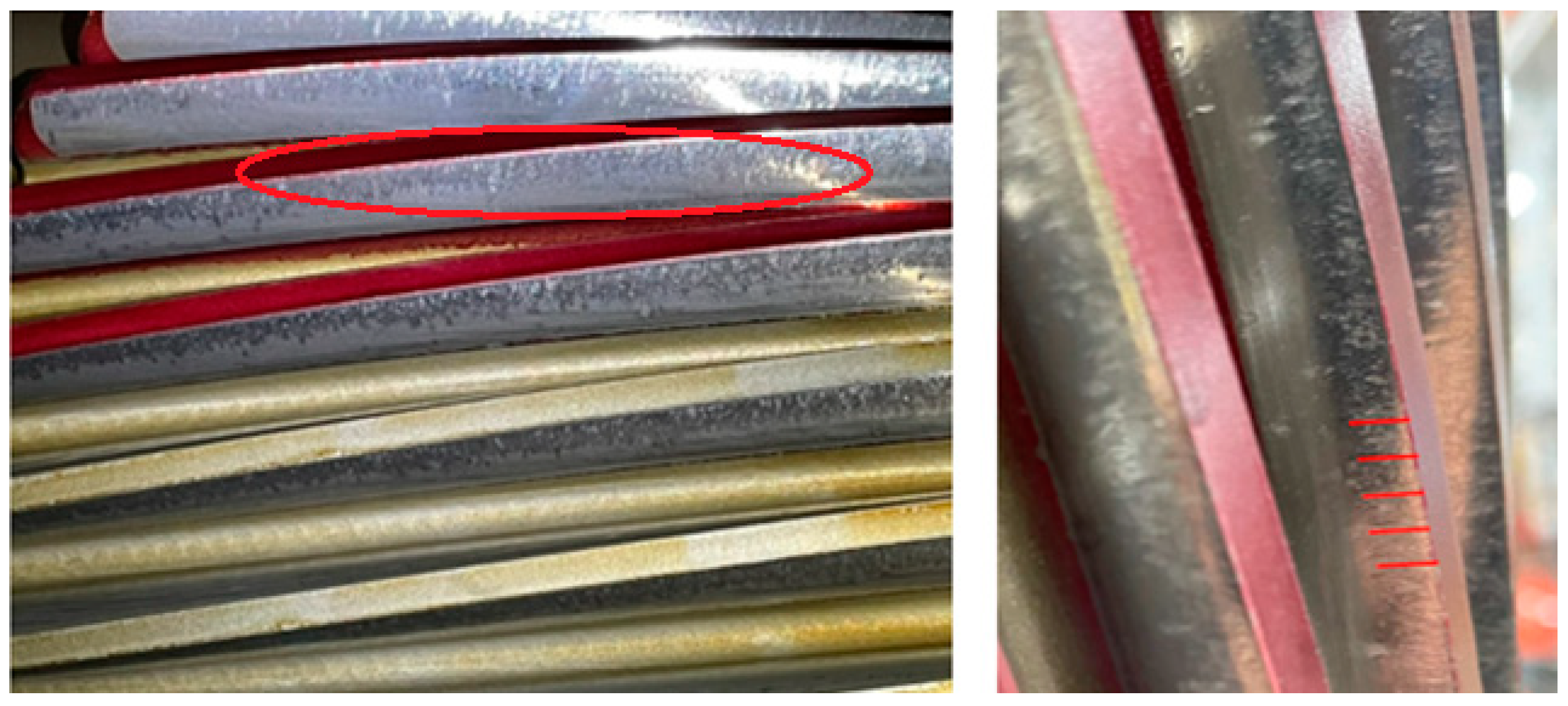
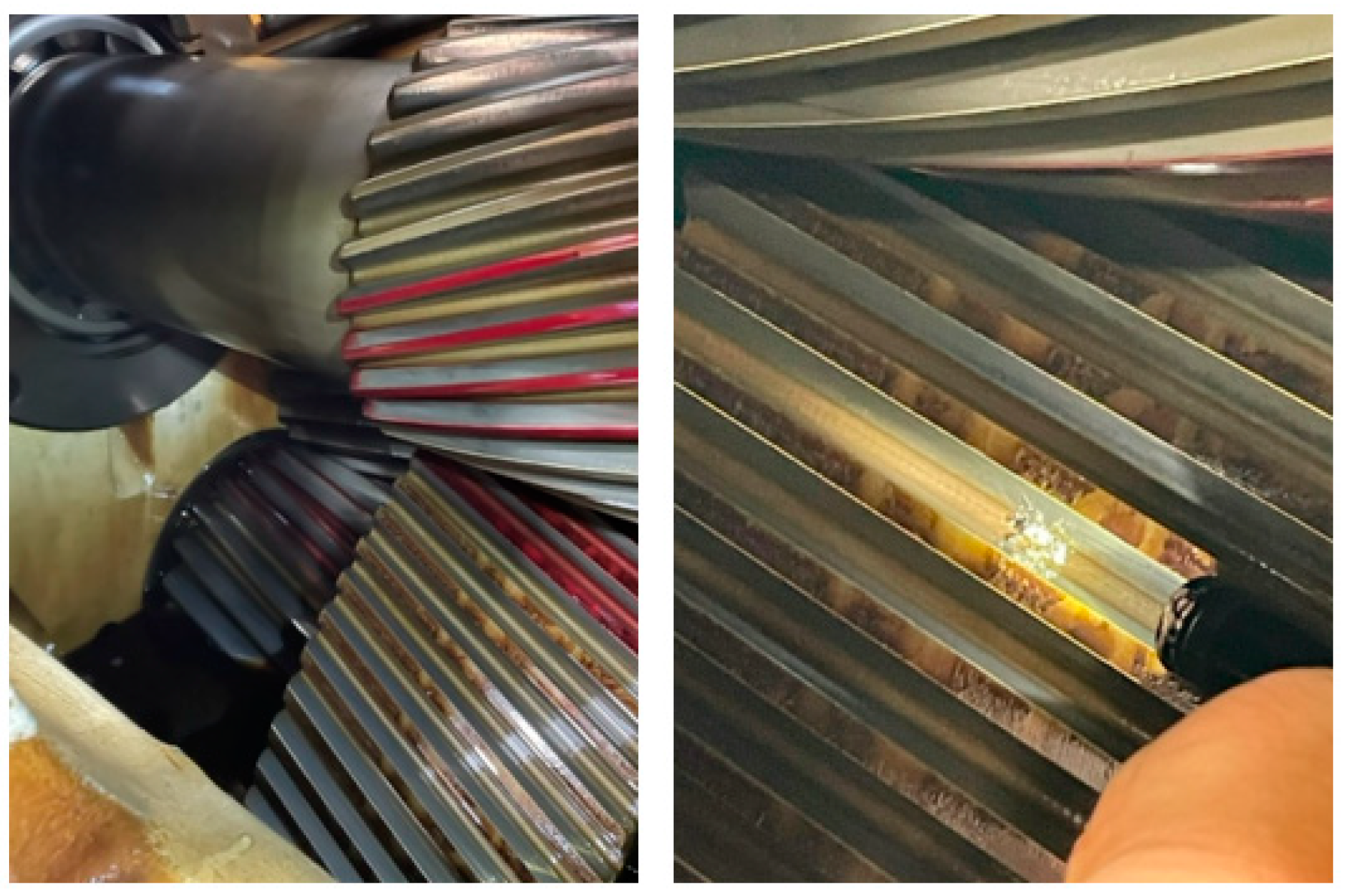
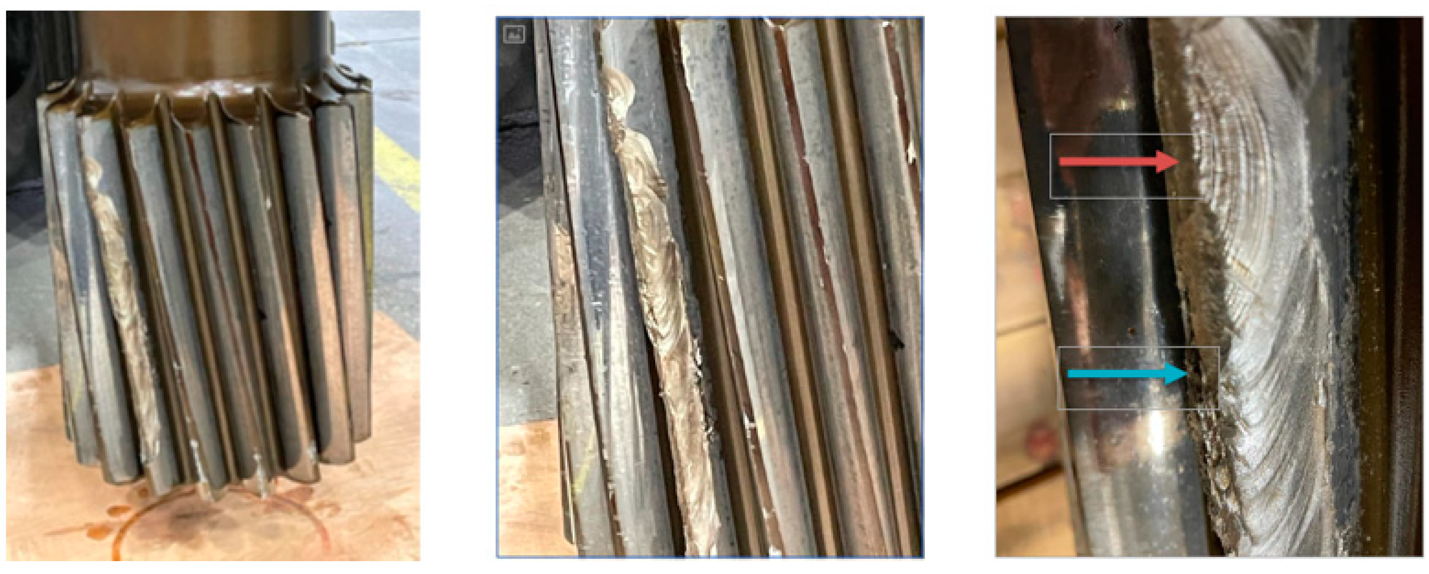
When looking closer at the high-speed shaft, noticeable adhesion wear marks are seen on the teeth’ faces and close to the flank. Adhesion wear marks were also localized on the teeth’ faces (
Figure 11 - right) and close to the flank (
Figure 11 – left).
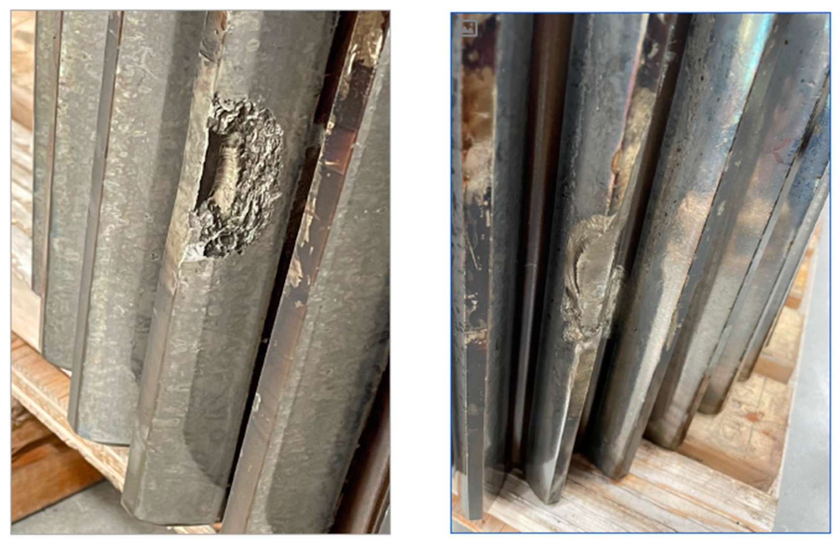
The low-speed gear presented many dents on the teeth, most likely due to material between the teeth contacting the intermediate shaft gear. When measured, the dents presented a surface roughness of around 4.8 microns (Rz) (
Figure 12).
A few particles were found stuck on the teeth roots when looking at the connection between the high-speed shaft and the intermediate spur gear (
Figure 13).
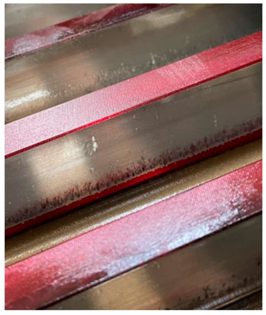
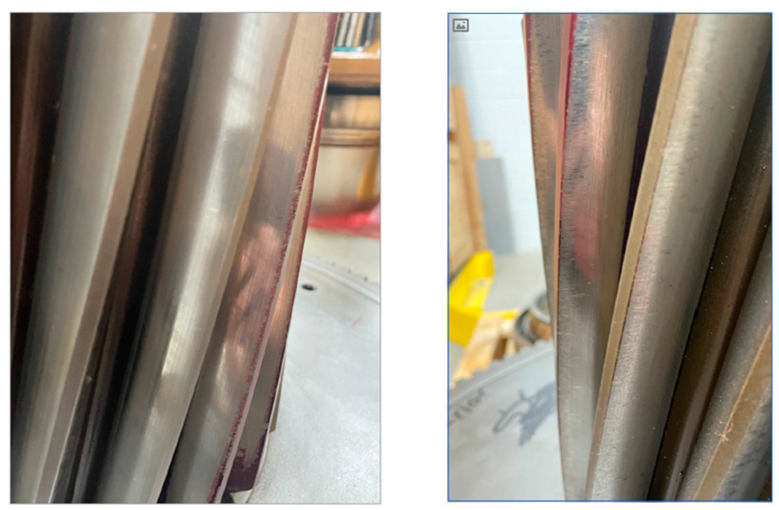
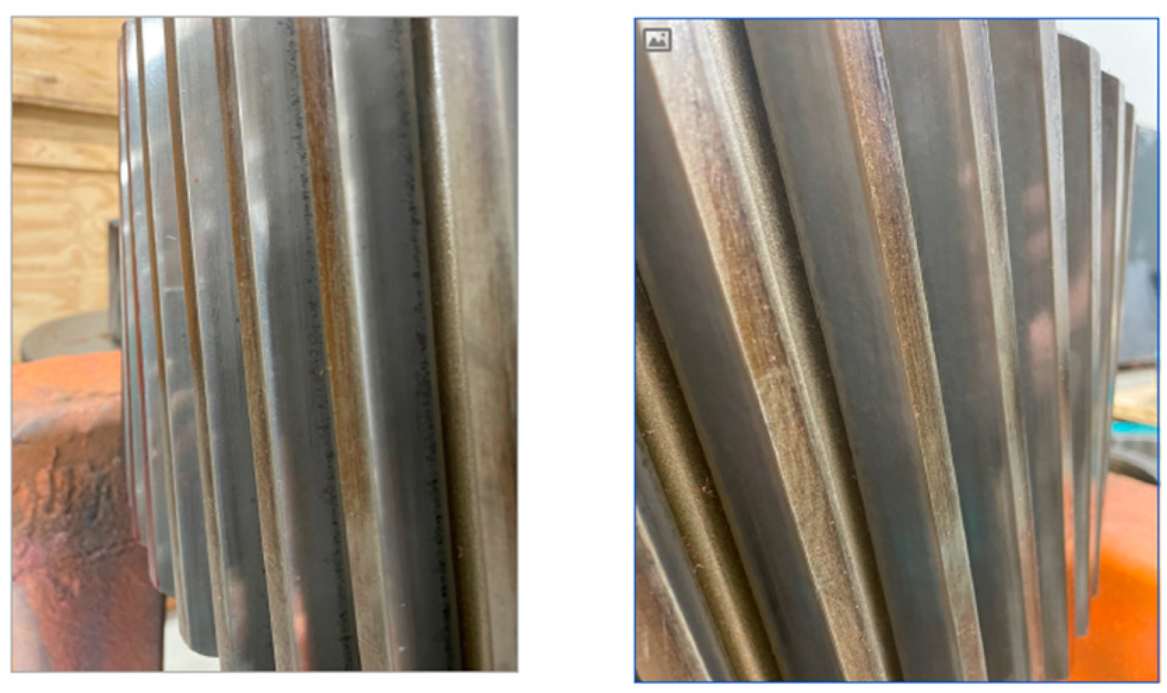
Figure 14 and
Figure 15 present a visual analysis that reveals that both sides of the gear do not present damages like dents, risks, or deep scratches; it has only a few fretting (risks) at the bottom of the teeth, but they are very minor and not significant for the gearbox’s functioning.
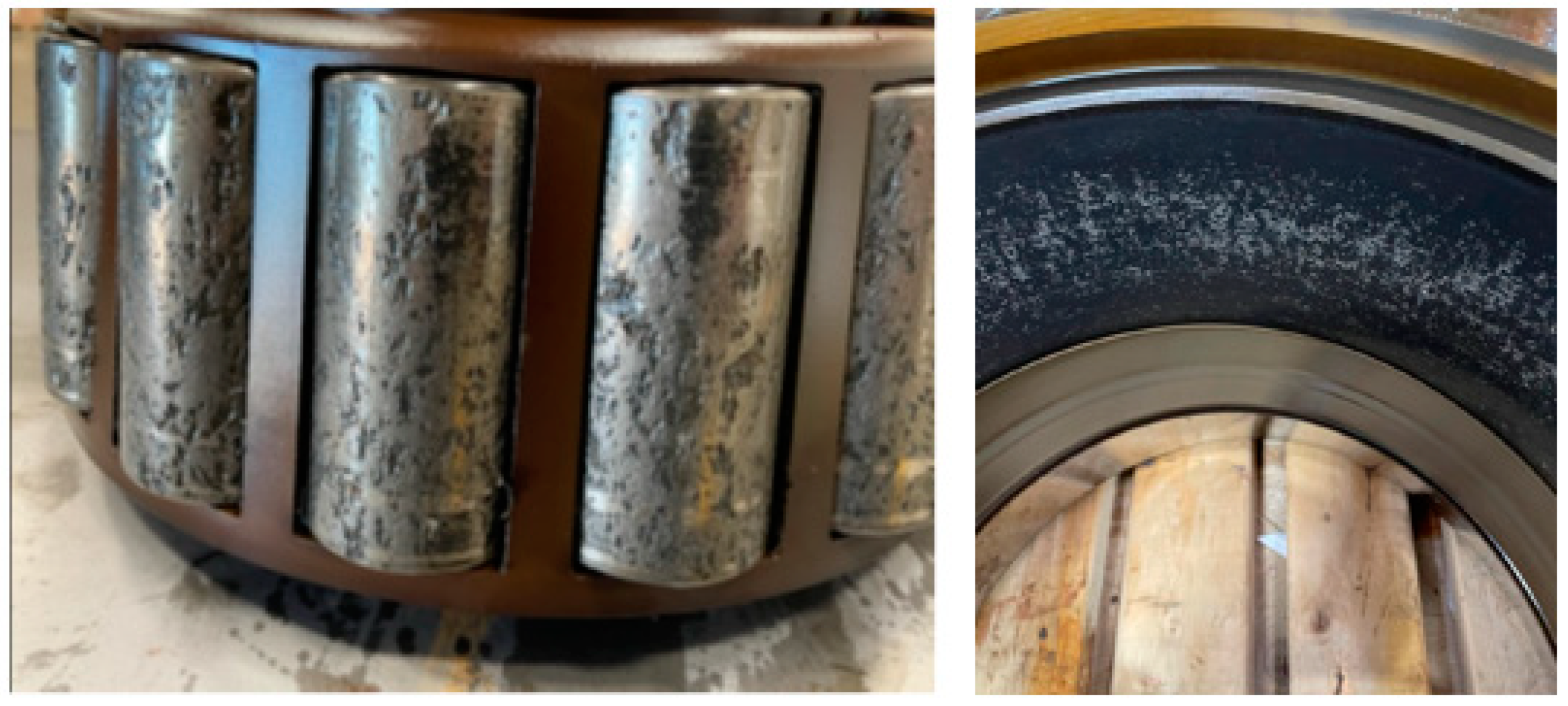
The sun shaft and the bearings had damage.
Figure 16 shows the conditions of the planet’s bearings. It exhibits the damages on the rollers, which had the black coating peeled off and pieces of material removed from them, and the inner part of the outer race, which also had the black coating detached from it.
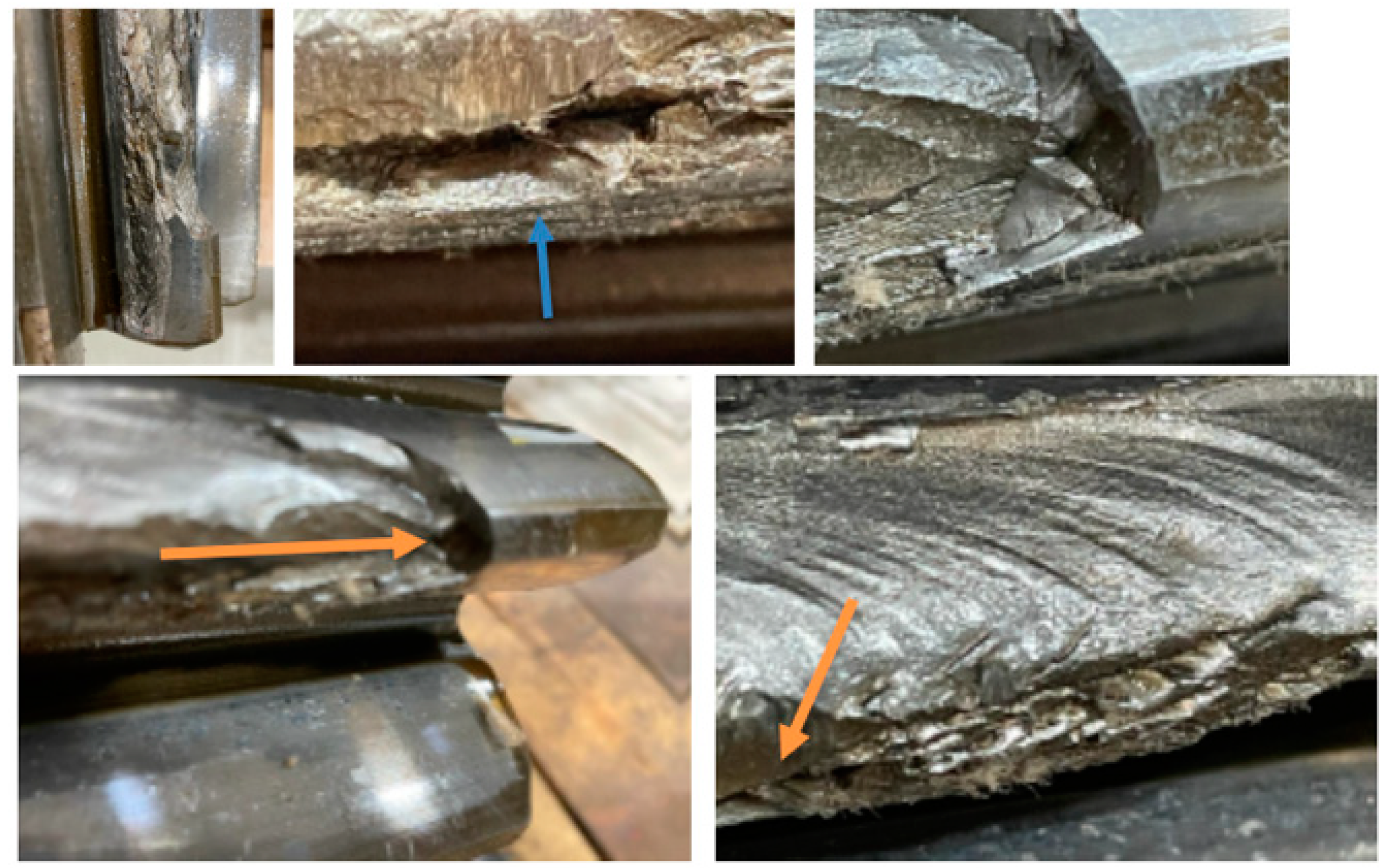
Among the gears analyzed, the sun shaft was the most damaged. It presents craters on the dedendum, flank, and tooth face. All defects are highly detrimental to the part and easily contribute to the final fracture (
Figure 17). The teeth show many crack initiation and beach marks. The crack nucleation started at the tip of the tooth and moved toward the flank (see arrows). Beach marks reveal the propagation of the cracks throughout the flank of the sun shaft tooth.
Moreover, on the top of the tooth, there is a crack where the material separation occurred, with a crack flowing throughout the tooth length, called Case/Core separation (
Figure 18). It usually happens when compressive residual stresses in the case exceed the tensile strength of the material in the core near the tooth tip due to excessive case depth at the tip (Errichello & Milburn, 2020) (Parrish, 1999) (AGMA, 2014). Internal cracks propagated, causing corners, edges, or entire teeth’s top land to separate. Cracks can appear immediately after the heat treatment, during handling or storage, or after time in service. (Parrish, 1999).
A lack of material is noticeable at the bottom of the tooth, which indicates a void generated by inclusion (
Figure 18 – bottom left). On the other side of the tooth, the flank had material severely removed and deformed plastically (smashed), which indicates that there were also heavy impacts on the gearbox (
Figure 19).
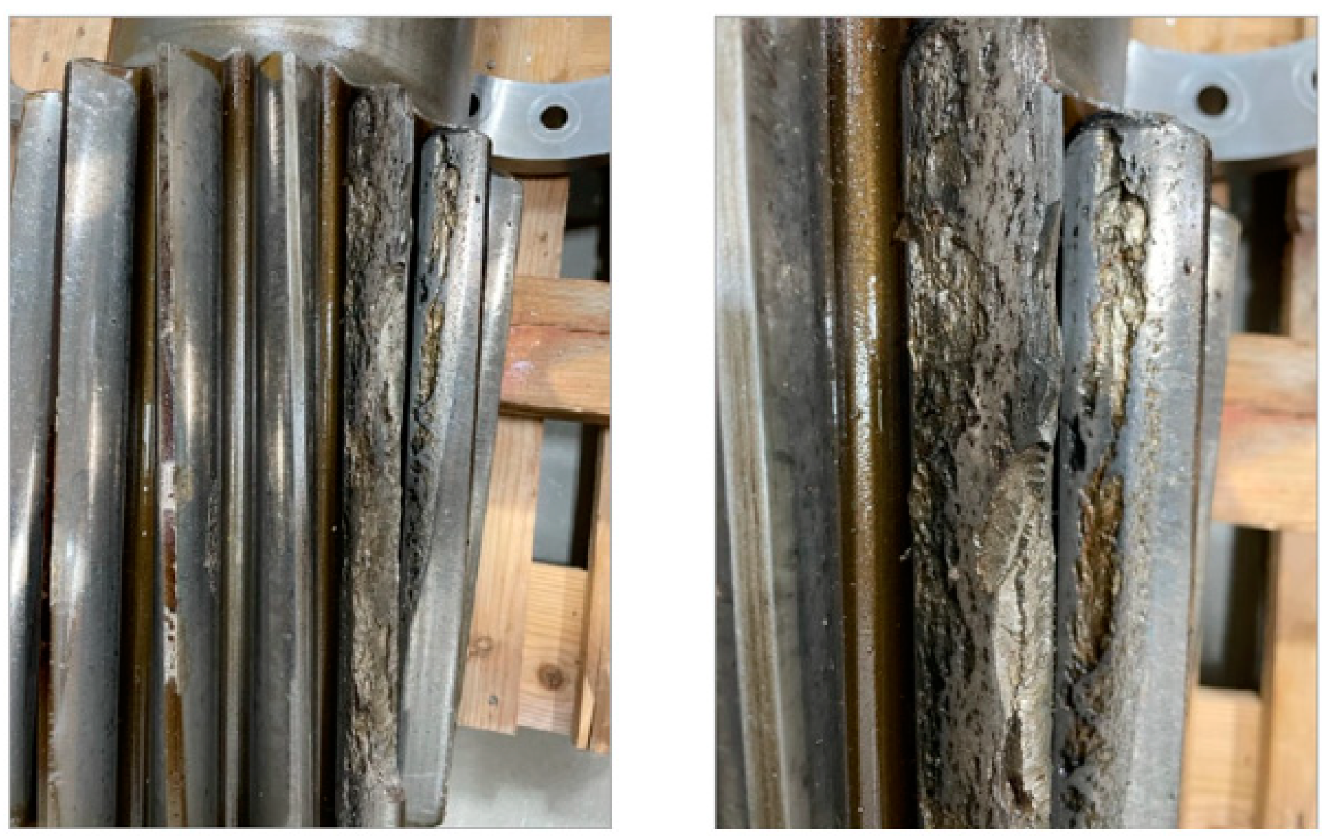
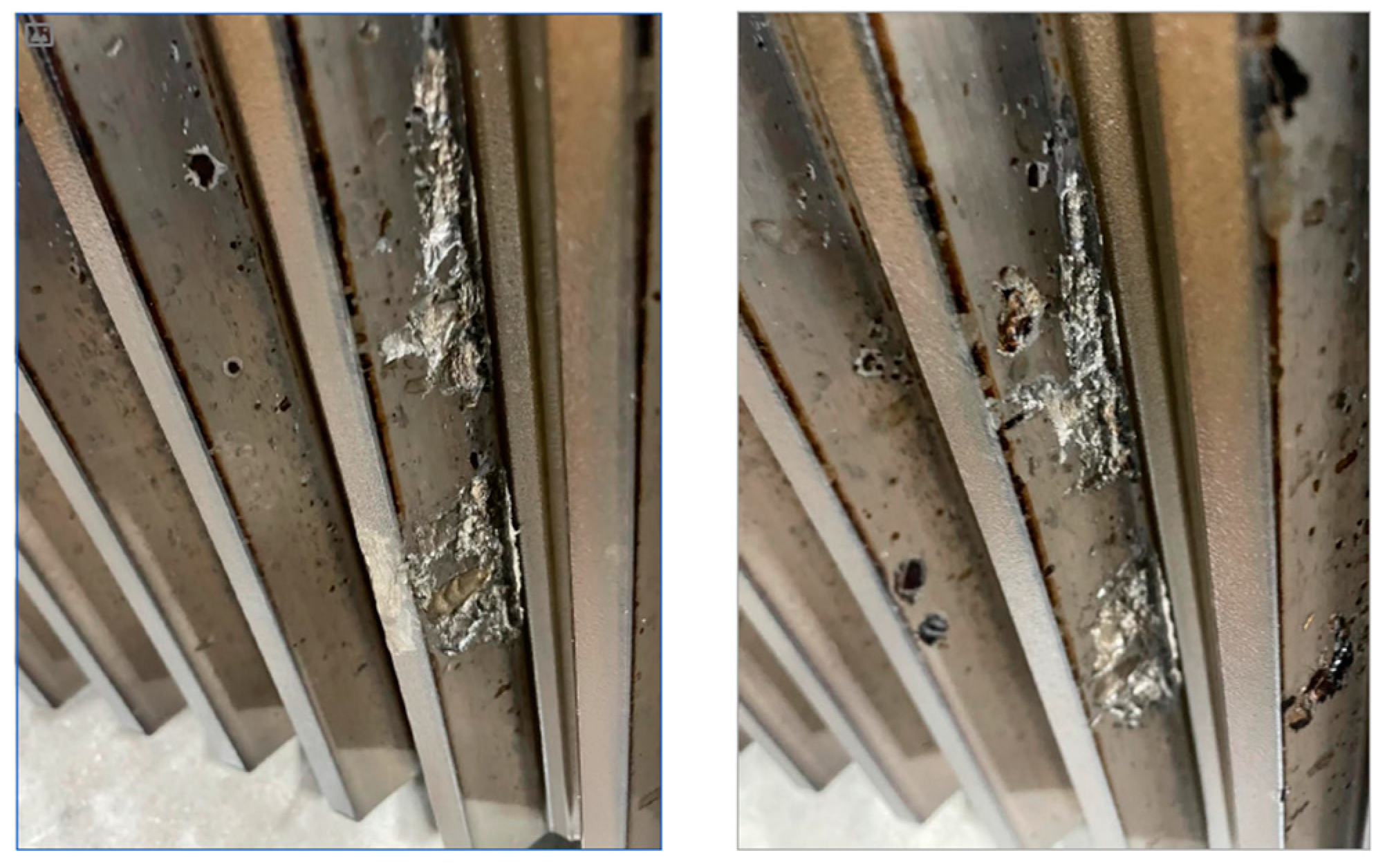
A visual inspection of the planet gears revealed severe damage with chunks of teeth missing. This occurred most likely due to pieces of the bearing rollers falling between the sun shaft and planet gears and at the bottom of the tooth ring (
Figure 20). Once the tooth ring has particles within the teeth, the contact with the planet gears generates intense damage (profound craters, dents, and marks).
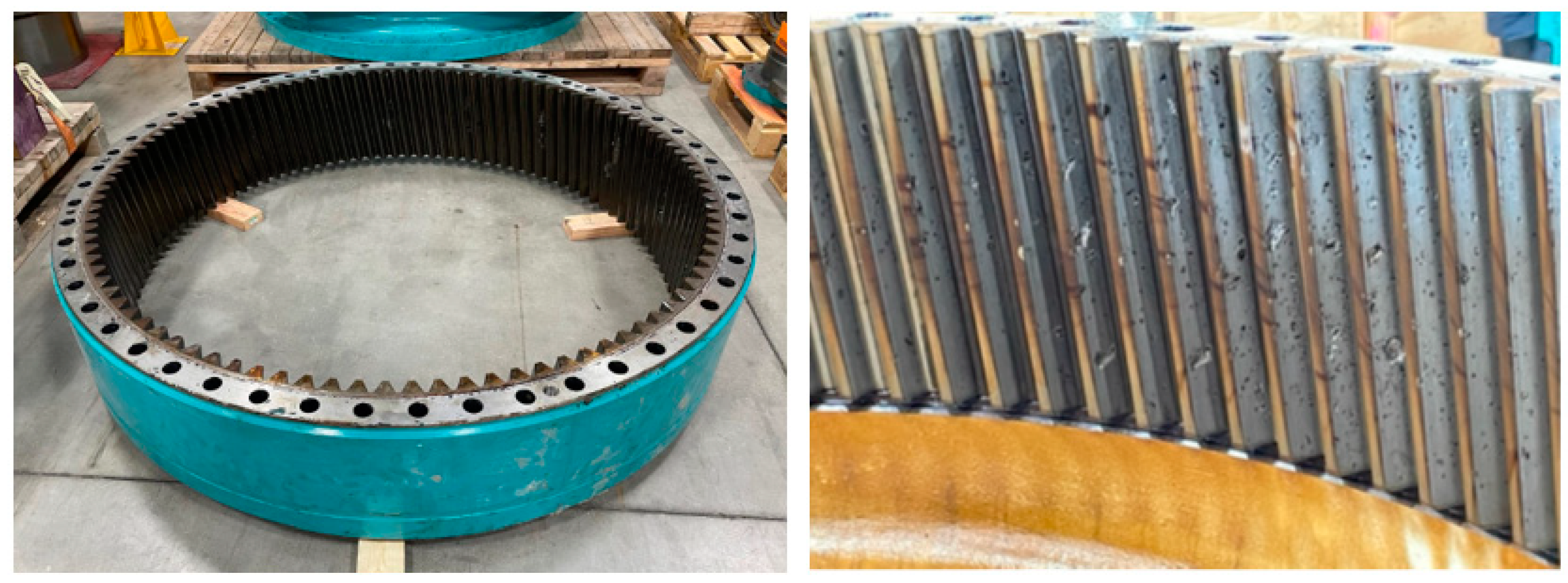
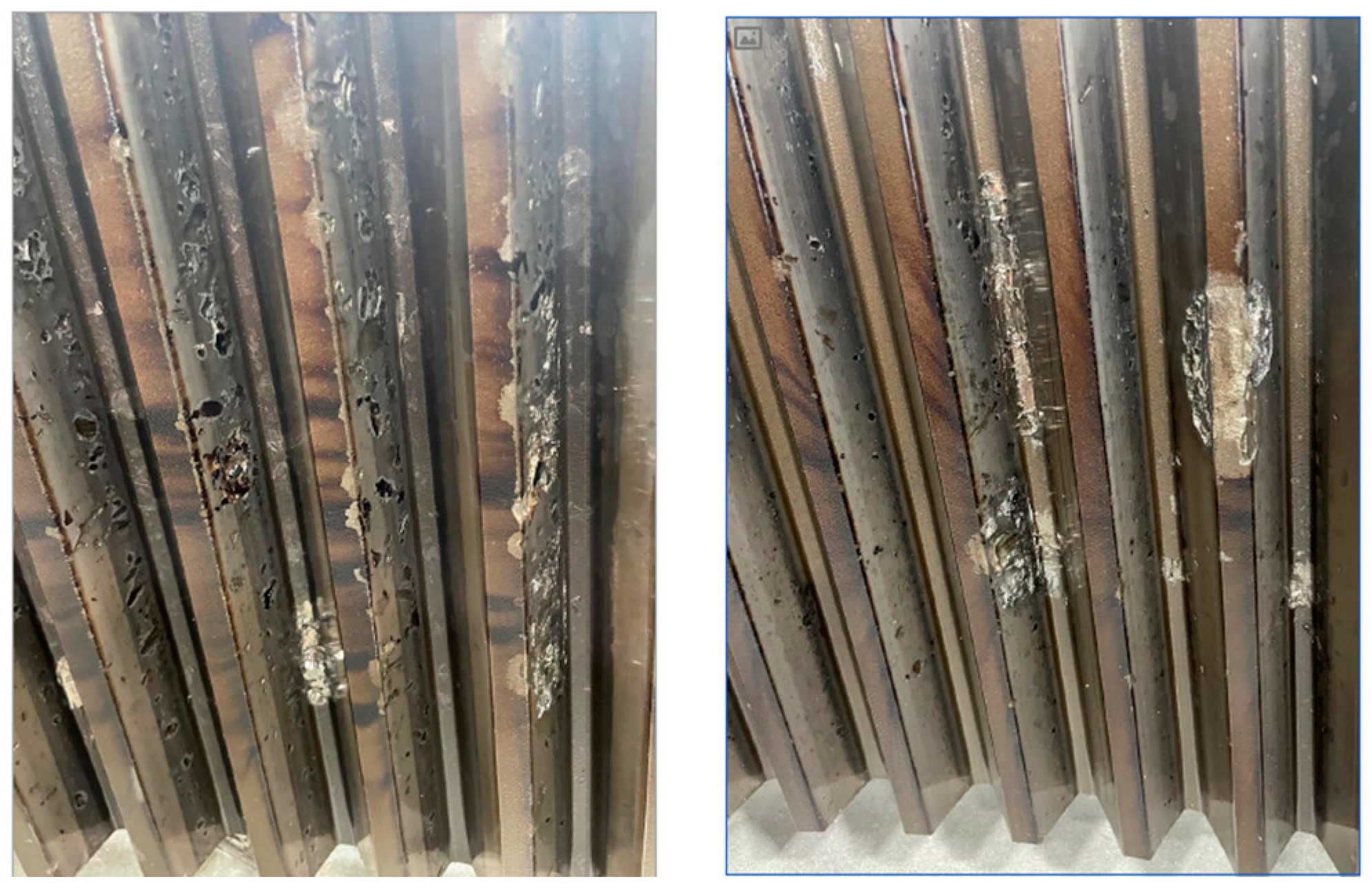
The next step was verifying the ring gear’s integrity, as shown in
Figure 21,
Figure 22 and
Figure 23. These figures show how severely the metallic particles damaged the tooth ring.
Based on the diagnosis performed it is possible to come up with the following statements. The coupling rubber spider was shattered. The oil in the gearbox was aired and had a thick foam resulting from coupling failure. The high-speed shaft presents slight fretting, which is expected due to high speed and poor lubrication. The intermediate gear also had a slight fretting. The sun shaft had large dents and craters, and a void was identified too; these are due to a lack of material cleanliness and problems in the case hardening process.
The planet gears, sun shaft, and roller bearings had chunks of material peeled off. And the tooth ring was completely damaged with many dents on the bottom of the gearbox due to the falling of the pieces of the parts‘ metal by gravity.
4. Conclusions
This work‘s objective was to diagnose a 1.6 MW gearbox‘s fracture, identifying the main reason for the failure and how the chain reaction happened that led to the catastrophic failure. A numerical Finite Element Analysis simulation determined the regions with the highest stresses. As expected, the contact of the teeth presented high stresses followed by the tooth fillets. However, differently from the calculations, the regions that had crack nucleated were close to the top land of the sun gear teeth.
With that said, the failure of the gearbox occurred because of a premature fracture of the sun shaft since it suffered predominantly a fatigue phenomenon (evidenced by beach marks on the tooth), even though a few signs of impact were observed. Moreover, there were multiple points where the teeth‘s surface had cracks initiated at the top land. In addition, a void was observed underneath the teeth due to a clear void in the sun shaft tooth (inclusion into the material). The gearbox was also compromised due to contamination of metallic particles peeling off planet gears’ bearing coating. The cause of black coating removal was pitting corrosion.
Although the lubrication pipes inspected were clean, allowing a smooth flow of oil throughout the lubrication system, another reason for the gearbox failure was the temporary poor lubrication on the planet bearings. This is attributed to the lubrication pump that falsely stepped on due to the coupling spider breakage, resulting in a temporary miss lubrication or even a pulsating lubrication on the planet bearing. The formation of oxides at pitting sites is enhanced with aeration in the system. The foaming oil in the oil level and inside the gearbox demonstrates that the lubrication line experienced high aeration.
To sum up, based on the data and analyses performed, the failure root cause of the gearbox was a combination of events such as; miss lubrication to the planet bearings, linked with a problem with the case depth of the sun gear from heat treatment (tensile residual stress), which triggered the phenomenon of fatigue, and impacted on the gearbox during operation; all these statements are evidenced from the fracture diagnose and analysis. With that said, the diagnosis demonstrated that a chain of events occurred, which led to the gearbox’s final catastrophic failure due to the falling of small and large particles from the roller bearings, sun shaft teeth, and planet gears into the oil and tooth ring internal teeth, contaminating the oil and damaging most of the gears.
5. Recommendations
This study reinforces the need for strict controls on heat treatment in terms of case depth thickness and hardness, control of raw material cleanliness, regular visual inspections, mainly by borescope, at the planet stage and high-speed shaft, vibration monitoring at the same stages, oil contamination monitoring, and regular checking of the lubrication system, manifold, filter cartridge, and coupling.
Author Contributions
All authors actively participated in all parts of the work. Conceptualization, Martins, J.A. and Romão, E.C.; methodology, Martins, J.A. and Romão, E.C.; software, Martins, J.A.; validation, Martins, J.A.; formal analysis, Martins, J.A. and Romão, E.C.; investigation, Martins, J.A.; writing—original draft preparation, Martins, J.A. and Romão, E.C.; writing—review and editing, Martins, J.A. and Romão, E.C.; supervision, Martins, J.A.; project administration, Martins, J.A. All authors have read and agreed to the published version of the manuscript.
Funding
The authors recognize the funding by DESCH North America when it comes to resources needed to develop this work.
Institutional Review Board Statement
Not applicable.
Informed Consent Statement
Not applicable.
Data Availability Statement
All data from this research are in the text.
Acknowledgments
DESCH North America for the support.
Conflicts of Interest
The authors declare no conflict of interest.
References
- Lauha Fried, S.S. Chapter 26 - Growth Trends and the Future of Wind Energy. Wind Energy Engineering 2017, 559–586. [Google Scholar]
- Akhmedovich, M.A.; Fazliddin, A. Current State Of Wind Power Industry. The American Journal of Engineering and Technology 2020, 14, 32–36. [Google Scholar] [CrossRef]
- Balat, M. A Review of Modern Wind Turbine Technology. Energy Sources, Part A: Recovery, Utilization, and Environmental Effects 2009, 31, 1561–1572. [Google Scholar] [CrossRef]
- Ahmet Duran Şahin, Progress and recent trends in wind energy. Progress in Energy and Combustion Science 2004, 30, 501–543. [CrossRef]
- Grogg, K. (2005). Grogg, Kira. “Harvesting the wind: the physics of wind turbines. Physics and Astronomy Comps Papers.
- Jayathilake, K.G.; Wijetunga, P.G. (2015). Design of Wind Turbine. Kristiansand, Norway: University of Agder.
- Sankar, S.; Nataraj, M.; Prabhu Raja, V. Failure Analysis of Bearing in Wind Turbine Generator Gearbox. Journal of Information Systems and Communication 2012, 3, 302–309. [Google Scholar]
- Bruce, T. (2016). Analysis of the premature failure of wind turbine gearbox bearings. University of Sheffield.
- Evans, M.H. An updated review: white etching cracks (WECs) and axial cracks in wind turbine gearbox bearings. Materials Science and Technology 2016, 32, 1133–1169. [Google Scholar] [CrossRef]
- Dilip Kr Singh, Jossy Kurien, Albert Villayamore, Study and analysis of wind turbine gearbox lubrication failure and its mitigation process. Materials Today: Proceedings 2021, 44, 3976–3983. [CrossRef]
- V. Rajinikanth, Manish Kumar Soni, B. Mahato, M. Ananda Rao, Microstructural investigation of rolling contact fatigue (RCF) on a failed planetary gear of a windmill gearbox. Engineering Failure Analysis 2021, 121, 105167. [Google Scholar] [CrossRef]
- Wang, Q., Zhu, Y., Zhang, Z. et al. Partial Load: A Key Factor Resulting in the Failure of Gear in the Wind Turbine Gearbox. J Fail. Anal. and Preven. 2016, 16, 109–122. [CrossRef]
- Bai, H.; Zhu, C.; Zhou, Y.; Chen, X.; Feng, H.; Ye, W. Study on Tooth Interior Fatigue Fracture Failure of Wind Turbine Gears. Metals 2020, 10, 1497. [Google Scholar] [CrossRef]
- Jerson, R.P. Vaz, David H. Wood, Performance analysis of wind turbines at low tip-speed ratio using the Betz-Goldstein model. Energy Conversion and Management 2016, 126, 662–672. [Google Scholar] [CrossRef]
- Tazi, N. , Chatelet, E., Bouzidi, Y. Wear Analysis of Wind Turbine Bearings. International Journal of Renewable Energy Research 2017, 7, 2120–2129. [Google Scholar]
- Provenza, F. (1996). Projetista de Máquinas, Ed. 71. São Paulo: Editora F. Provenza. (in portuguese).
- Rexroth, B. (2015). GPV - Gearboxes for wind turbines - GPV 457.1 S 44 60HZ 89–926 series. Witten: Bosch Rexroth AG.
|
Disclaimer/Publisher’s Note: The statements, opinions and data contained in all publications are solely those of the individual author(s) and contributor(s) and not of MDPI and/or the editor(s). MDPI and/or the editor(s) disclaim responsibility for any injury to people or property resulting from any ideas, methods, instructions or products referred to in the content. |
© 2024 by the authors. Licensee MDPI, Basel, Switzerland. This article is an open access article distributed under the terms and conditions of the Creative Commons Attribution (CC BY) license (http://creativecommons.org/licenses/by/4.0/).
